US5070431A - Display board illuminating device for passive displays - Google Patents
Display board illuminating device for passive displaysDownload PDFInfo
- Publication number
- US5070431A US5070431AUS07/559,358US55935890AUS5070431AUS 5070431 AUS5070431 AUS 5070431AUS 55935890 AUS55935890 AUS 55935890AUS 5070431 AUS5070431 AUS 5070431A
- Authority
- US
- United States
- Prior art keywords
- guide plate
- light guide
- display board
- light
- back surface
- Prior art date
- Legal status (The legal status is an assumption and is not a legal conclusion. Google has not performed a legal analysis and makes no representation as to the accuracy of the status listed.)
- Expired - Fee Related
Links
- 239000003086colorantSubstances0.000claimsdescription3
- 230000003287optical effectEffects0.000abstractdescription5
- 238000009792diffusion processMethods0.000description6
- 239000004925Acrylic resinSubstances0.000description4
- 229920000178Acrylic resinPolymers0.000description4
- 238000005286illuminationMethods0.000description4
- 239000000463materialSubstances0.000description4
- 238000004519manufacturing processMethods0.000description2
- 230000002093peripheral effectEffects0.000description2
- 238000010276constructionMethods0.000description1
- 230000000694effectsEffects0.000description1
- 239000011521glassSubstances0.000description1
- 230000001788irregularEffects0.000description1
- 239000004973liquid crystal related substanceSubstances0.000description1
- 238000000034methodMethods0.000description1
- 239000003973paintSubstances0.000description1
- 238000000926separation methodMethods0.000description1
- 238000006467substitution reactionMethods0.000description1
- 229920003002synthetic resinPolymers0.000description1
- 239000000057synthetic resinSubstances0.000description1
Images


Classifications
- G—PHYSICS
- G02—OPTICS
- G02B—OPTICAL ELEMENTS, SYSTEMS OR APPARATUS
- G02B6/00—Light guides; Structural details of arrangements comprising light guides and other optical elements, e.g. couplings
- G02B6/0001—Light guides; Structural details of arrangements comprising light guides and other optical elements, e.g. couplings specially adapted for lighting devices or systems
- G02B6/0011—Light guides; Structural details of arrangements comprising light guides and other optical elements, e.g. couplings specially adapted for lighting devices or systems the light guides being planar or of plate-like form
- G02B6/0013—Means for improving the coupling-in of light from the light source into the light guide
- G02B6/0015—Means for improving the coupling-in of light from the light source into the light guide provided on the surface of the light guide or in the bulk of it
- G02B6/002—Means for improving the coupling-in of light from the light source into the light guide provided on the surface of the light guide or in the bulk of it by shaping at least a portion of the light guide, e.g. with collimating, focussing or diverging surfaces
- G02B6/0021—Means for improving the coupling-in of light from the light source into the light guide provided on the surface of the light guide or in the bulk of it by shaping at least a portion of the light guide, e.g. with collimating, focussing or diverging surfaces for housing at least a part of the light source, e.g. by forming holes or recesses
- G—PHYSICS
- G02—OPTICS
- G02B—OPTICAL ELEMENTS, SYSTEMS OR APPARATUS
- G02B6/00—Light guides; Structural details of arrangements comprising light guides and other optical elements, e.g. couplings
- G02B6/24—Coupling light guides
- G02B6/42—Coupling light guides with opto-electronic elements
- G02B6/4298—Coupling light guides with opto-electronic elements coupling with non-coherent light sources and/or radiation detectors, e.g. lamps, incandescent bulbs, scintillation chambers
- G—PHYSICS
- G02—OPTICS
- G02F—OPTICAL DEVICES OR ARRANGEMENTS FOR THE CONTROL OF LIGHT BY MODIFICATION OF THE OPTICAL PROPERTIES OF THE MEDIA OF THE ELEMENTS INVOLVED THEREIN; NON-LINEAR OPTICS; FREQUENCY-CHANGING OF LIGHT; OPTICAL LOGIC ELEMENTS; OPTICAL ANALOGUE/DIGITAL CONVERTERS
- G02F1/00—Devices or arrangements for the control of the intensity, colour, phase, polarisation or direction of light arriving from an independent light source, e.g. switching, gating or modulating; Non-linear optics
- G02F1/01—Devices or arrangements for the control of the intensity, colour, phase, polarisation or direction of light arriving from an independent light source, e.g. switching, gating or modulating; Non-linear optics for the control of the intensity, phase, polarisation or colour
- G02F1/13—Devices or arrangements for the control of the intensity, colour, phase, polarisation or direction of light arriving from an independent light source, e.g. switching, gating or modulating; Non-linear optics for the control of the intensity, phase, polarisation or colour based on liquid crystals, e.g. single liquid crystal display cells
- G02F1/133—Constructional arrangements; Operation of liquid crystal cells; Circuit arrangements
- G02F1/1333—Constructional arrangements; Manufacturing methods
- G02F1/1335—Structural association of cells with optical devices, e.g. polarisers or reflectors
- G02F1/1336—Illuminating devices
- G02F1/133615—Edge-illuminating devices, i.e. illuminating from the side
- G—PHYSICS
- G02—OPTICS
- G02B—OPTICAL ELEMENTS, SYSTEMS OR APPARATUS
- G02B6/00—Light guides; Structural details of arrangements comprising light guides and other optical elements, e.g. couplings
- G02B6/0001—Light guides; Structural details of arrangements comprising light guides and other optical elements, e.g. couplings specially adapted for lighting devices or systems
- G02B6/0011—Light guides; Structural details of arrangements comprising light guides and other optical elements, e.g. couplings specially adapted for lighting devices or systems the light guides being planar or of plate-like form
- G02B6/0033—Means for improving the coupling-out of light from the light guide
- G02B6/0035—Means for improving the coupling-out of light from the light guide provided on the surface of the light guide or in the bulk of it
- G02B6/0036—2-D arrangement of prisms, protrusions, indentations or roughened surfaces
- G—PHYSICS
- G02—OPTICS
- G02B—OPTICAL ELEMENTS, SYSTEMS OR APPARATUS
- G02B6/00—Light guides; Structural details of arrangements comprising light guides and other optical elements, e.g. couplings
- G02B6/0001—Light guides; Structural details of arrangements comprising light guides and other optical elements, e.g. couplings specially adapted for lighting devices or systems
- G02B6/0011—Light guides; Structural details of arrangements comprising light guides and other optical elements, e.g. couplings specially adapted for lighting devices or systems the light guides being planar or of plate-like form
- G02B6/0033—Means for improving the coupling-out of light from the light guide
- G02B6/0058—Means for improving the coupling-out of light from the light guide varying in density, size, shape or depth along the light guide
- G02B6/0061—Means for improving the coupling-out of light from the light guide varying in density, size, shape or depth along the light guide to provide homogeneous light output intensity
- G—PHYSICS
- G02—OPTICS
- G02B—OPTICAL ELEMENTS, SYSTEMS OR APPARATUS
- G02B6/00—Light guides; Structural details of arrangements comprising light guides and other optical elements, e.g. couplings
- G02B6/0001—Light guides; Structural details of arrangements comprising light guides and other optical elements, e.g. couplings specially adapted for lighting devices or systems
- G02B6/0011—Light guides; Structural details of arrangements comprising light guides and other optical elements, e.g. couplings specially adapted for lighting devices or systems the light guides being planar or of plate-like form
- G02B6/0066—Light guides; Structural details of arrangements comprising light guides and other optical elements, e.g. couplings specially adapted for lighting devices or systems the light guides being planar or of plate-like form characterised by the light source being coupled to the light guide
- G02B6/0068—Arrangements of plural sources, e.g. multi-colour light sources
- G—PHYSICS
- G02—OPTICS
- G02B—OPTICAL ELEMENTS, SYSTEMS OR APPARATUS
- G02B6/00—Light guides; Structural details of arrangements comprising light guides and other optical elements, e.g. couplings
- G02B6/0001—Light guides; Structural details of arrangements comprising light guides and other optical elements, e.g. couplings specially adapted for lighting devices or systems
- G02B6/0011—Light guides; Structural details of arrangements comprising light guides and other optical elements, e.g. couplings specially adapted for lighting devices or systems the light guides being planar or of plate-like form
- G02B6/0066—Light guides; Structural details of arrangements comprising light guides and other optical elements, e.g. couplings specially adapted for lighting devices or systems the light guides being planar or of plate-like form characterised by the light source being coupled to the light guide
- G02B6/0073—Light emitting diode [LED]
- G—PHYSICS
- G02—OPTICS
- G02B—OPTICAL ELEMENTS, SYSTEMS OR APPARATUS
- G02B6/00—Light guides; Structural details of arrangements comprising light guides and other optical elements, e.g. couplings
- G02B6/0001—Light guides; Structural details of arrangements comprising light guides and other optical elements, e.g. couplings specially adapted for lighting devices or systems
- G02B6/0011—Light guides; Structural details of arrangements comprising light guides and other optical elements, e.g. couplings specially adapted for lighting devices or systems the light guides being planar or of plate-like form
- G02B6/0081—Mechanical or electrical aspects of the light guide and light source in the lighting device peculiar to the adaptation to planar light guides, e.g. concerning packaging
- Y—GENERAL TAGGING OF NEW TECHNOLOGICAL DEVELOPMENTS; GENERAL TAGGING OF CROSS-SECTIONAL TECHNOLOGIES SPANNING OVER SEVERAL SECTIONS OF THE IPC; TECHNICAL SUBJECTS COVERED BY FORMER USPC CROSS-REFERENCE ART COLLECTIONS [XRACs] AND DIGESTS
- Y10—TECHNICAL SUBJECTS COVERED BY FORMER USPC
- Y10S—TECHNICAL SUBJECTS COVERED BY FORMER USPC CROSS-REFERENCE ART COLLECTIONS [XRACs] AND DIGESTS
- Y10S362/00—Illumination
- Y10S362/80—Light emitting diode
Definitions
- the present inventionrelates to a display board illuminating device for a display unit including a display board, such as a dial scale of a tuner or a dial plate.
- FIG. 1shows an example of conventional devices for illuminating a display board.
- this conventional deviceincludes a light guide plate 2 placed to face the back of an elongated rectangular display board 1 and a light emitting element 3, functioning as a light source, disposed to face an end surface of the light guide plate 2 at one side in the longitudinal direction of the light guide plate 2.
- the back surface 2a of the light guide plate 2is formed into a rough surface or covered with a white printing material in order to diffuse the light.
- the light emitted from the light emitting element 3enters the light guide plate 2, and guided to a predetermined area of the back surface of the display board 1, while being reflected and diffused within the light guide plate 2.
- an optical axis of the light incident into the light guide plate, which is diffracted at the side end surface, with respect to the main surface of the light guide plateis made small.
- FIG. 1is a longitudinal sectional view of a conventional display board illuminating device
- FIGS. 4A through 4Care front, left side, and right side views of the light guide plate included in the display board illuminating device shown in FIG. 2;
- FIG. 5is an enlarged view of a portion A in FIG. 3;
- FIGS. 6 through 8are graphs for explaining the function of the display board illuminating device shown in FIGS. 2 through 5;
- FIG. 9is a longitudinal sectional view of a major part of a display board illuminating device as a second embodiment of the invention.
- FIGS. 10 and 11are perspective and longitudinal sectional views respectively, of a main part of a display board illuminating device as a third embodiment of the invention.
- FIGS. 2 through 5show a display board illuminating device as the first embodiment of the present invention.
- Light emitting elements 15 and 16 functioning as light sourceare provided to respectively face left and right end surfaces of the light guide plate 2, the end surfaces lying transverse to a longitudinal axis of the light guide plate 2.
- the light emitting elements 15 and 16are mounted on a fitting plate made of a region and having a rectangular tabular shape, placed on the rear side of the light guide plate 12.
- the above-described LCD 11, light guide plate 12, diffusion plate 13, and the fitting plate 18are stacked with each other and housed in a frame member 20 which is formed into a rectangular parallelepiped.
- the frame member 20is provided with an opening 20a of a rectangular shape for viewing the display surface of the LCD 11.
- the inner surfaces of the recesses 12a and 12b formed on both of the left and right side end surfaces of the light guide plate 12are inclined toward the center of the light guide plate 12 in the direction of the display board, i.e., the LCD 11. More specifically, the end surfaces are inclined toward the center of the light guide plate 12 with respect to a perpendicular in the direction of the display board 11. The function of these inclined surfaces will be described hereinafter.
- the refractive index n of the light guide plate 12is expressed by the following equations: ##EQU1##
- a graph shown in FIG. 6can be drawn from the equation (1').
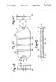
- the angle of inclination of the inner surfaces of the recesses 12a and 12bis not uniform for the whole surface of the inner surfaces. More specifically, at central portions 12e and 12f in the transverse direction of the light guide plate 12 and in the vicinities thereof (shown in FIG. 4A), the angle of inclination is made smallest. More specifically, this configuration is employed so that the light issued from each of the light emitting elements 15 and 16 is especially guided to further positions along a central line in the longitudinal direction of the light guide plate 12. By this feature the efficiency in the utilization of light is further improved.
- a group of inclined reflecting surfacesis provided in the back surface, i.e., the surface on the opposite side of the surface facing the back surface of the LCD 11.
- the group of inclined reflecting surfacesis made of a plurality of linear notches 12g arranged in the longitudinal direction of the light guide plate 12, each of the notches 12g extending along a transverse direction of the light guide plate, and having a cross-section of an equilateral triangle. The reflection of light by the group of inclined reflecting surfaces will be described hereinafter.
- ⁇ 4represents an angle of the surface of each notch 12g forming the group of the inclined reflective surfaces relative to the back surface 12c of the light guide plate 12.
- ⁇ 5represents a sum of the angle of incidence and the angle of emergence of the light reflected by an inclined reflecting surface forming each notch 12g.
- ⁇ 6represents an angle of the optical axis of the light reflected by the inclined reflecting surface with respect to the back surface 12c of the light guide plate 12.
- nrepresents the refractive index of the light guide plate 12
- narepresents the refractive index of air which is equal to 1.
- ⁇ 5equals 83.62° when ⁇ 4 is set at 48° from a range between 0° and 48° and correspondingly ⁇ 6 is set at 96° from a range between 56° and 96°.
- ⁇ 2should be set at 60° for setting ⁇ 3 at 10°, if ⁇ 1 is equal to 50°.
- FIG. 9is a cross sectional view of the recess 12a and its peripherals formed on the left side end of the light guide plate 12 which is a major part in the second embodiment of the display board illuminating device according to the present invention.
- This display board illuminating devicehas the same structure as the device shown in FIGS. 2 through 5 except the portions described below, and the description of the structure will not be repeated.
- like reference numeralsare used for designating portions the same as or corresponding to the portions of the device shown in FIGS. 2 through 5, and the same applies to the description of further embodiments.
- the inner surface of the recess 12a formed on the left side end of the light guide plate 12is inclined toward the center of the light guide plate 12 in the direction of the LCD 11. Furthermore, the angle of inclination (the angle between the inner surface and the back surface of the light guide plate) is gradually reduced in the direction of the LCD 11. In the case of this configuration, of course the function of the display board illuminating device shown in FIGS. 2 through 5 is obtained. Furthermore, by suitably determining the rate of change in the inclination of the inner surface of the recess 12a, it is possible to convert almost all of the light beams emitted from the light emitting element 15 and incident on different portions of the inner surface of the recess at different angles of incidence into parallel lights within the light guide plate 12. By this feature, irregular reflection of light is prevented so that the light can be utilized further efficiently.
- FIGS. 10 and 11illustrate the left side end portion of a light guide plate 12 shown as a major part of the third embodiment of the display board illuminating device according to the present invention.
- the whole surface of the side end of the light guide plate 12qis made flat, and the surface is inclined toward the center of the light guide plate 12 in the direction of the back surface of the LCD 11.
- the light beams emitted by the light emitting element 15 and incident on different portions of the side end surfaces 12qmay not easily be converted to parallel lights in the light guide plate 12.
- the effect obtained by the display board illuminating device shown in FIGS. 2 through 5can sufficiently be obtained. Since the side end surface 12q of the light guide plate 12 is made flat, the production process thereof is extremely simple, so that the production cost can be easily reduced.
- the display board illuminating apparatushaving various configurations for guiding the light emitted from the light emitting element to further locations have been described.
- the advantageous features of the described devicesmay be combined to provide a display board illuminating device having all advantageous features of the described example. In such a case, the light is guided to further locations at an extremely high efficiency, and an optimum utilization of light can be attained.
- a side end surface of the light guide plate arranged to face the back surface of the display board to be illuminated, the side end surface crossing the longitudinal direction of the light guide plate,is inclined toward the center of the light guide plate in the direction of the display board.
Landscapes
- Physics & Mathematics (AREA)
- General Physics & Mathematics (AREA)
- Optics & Photonics (AREA)
- Nonlinear Science (AREA)
- Mathematical Physics (AREA)
- Chemical & Material Sciences (AREA)
- Crystallography & Structural Chemistry (AREA)
- Light Guides In General And Applications Therefor (AREA)
- Planar Illumination Modules (AREA)
- Liquid Crystal (AREA)
- Devices For Indicating Variable Information By Combining Individual Elements (AREA)
Abstract
Description
1. Field of the Invention
The present invention relates to a display board illuminating device for a display unit including a display board, such as a dial scale of a tuner or a dial plate.
2. Description of Background Information
FIG. 1 shows an example of conventional devices for illuminating a display board. As shown, this conventional device includes alight guide plate 2 placed to face the back of an elongatedrectangular display board 1 and alight emitting element 3, functioning as a light source, disposed to face an end surface of thelight guide plate 2 at one side in the longitudinal direction of thelight guide plate 2. Theback surface 2a of thelight guide plate 2 is formed into a rough surface or covered with a white printing material in order to diffuse the light.
In the illuminating device having the construction described above, the light emitted from thelight emitting element 3 enters thelight guide plate 2, and guided to a predetermined area of the back surface of thedisplay board 1, while being reflected and diffused within thelight guide plate 2.
In the case of the conventional illuminating device as described above, there was a problem that the light from thelight emitting element 3 does not reach sufficiently to the opposite end of the display board especially when the size of the display board in the longitudinal direction is large, thereby making it difficult to illuminate the whole area of thedisplay board 1 at a uniform illumination level. Furthermore, the light issued from thelight emitting element 3 is not efficiently introduced to the back surface of thedisplay board 1, causing a problem that the illuminating light is dissipated wastefully.
The present invention is based on the recognition of the above-mentioned problem, and an object of the present invention is to provide a display board illuminating device by which the whole area of the display board is illuminated at a uniform illumination level, and the light is utilized at high efficiency.
A display board illuminating device according to the present invention includes a light guide plate placed to face the back surface of a display board to be illuminated and a light source arranged to face a side end surface of the light guide plate crossing a longitudinal axis of the light guide plate. The side end surface of the light guide plate is inclined toward the center of the light guide plate in the direction of the display board.
By the structure described above, an optical axis of the light incident into the light guide plate, which is diffracted at the side end surface, with respect to the main surface of the light guide plate is made small.
FIG. 1 is a longitudinal sectional view of a conventional display board illuminating device;
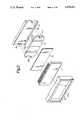
FIGS. 2 and 3 are exploded and longitudinal sectional views respectively, of a display unit including a display board illuminating device as a first embodiment of the present invention and a display board to be illuminated by the illuminating device;
FIGS. 4A through 4C are front, left side, and right side views of the light guide plate included in the display board illuminating device shown in FIG. 2;
FIG. 4D is a sectional view taken along a line IVd--IVd of FIG. 4A;
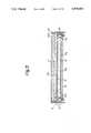
FIG. 5 is an enlarged view of a portion A in FIG. 3;
FIGS. 6 through 8 are graphs for explaining the function of the display board illuminating device shown in FIGS. 2 through 5;
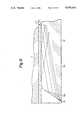
FIG. 9 is a longitudinal sectional view of a major part of a display board illuminating device as a second embodiment of the invention; and
FIGS. 10 and 11 are perspective and longitudinal sectional views respectively, of a main part of a display board illuminating device as a third embodiment of the invention.
The preferred embodiments of the present invention will be described with reference to FIGS. 2 through of the accompanying drawings.
FIGS. 2 through 5 show a display board illuminating device as the first embodiment of the present invention.
As shown in FIGS. 2 and 3, the display board illuminating device includes alight guide plate 12 which is placed to face the back surface of an LCD (liquid-crystal display) having a rectangular tabular shape, provided as a display board to be illuminated. The device further includes adiffusion plate 13 of rectangular tabular shape, inserted between theLCD 11 and thelight guide plate 12. As indicated also in FIGS. 4A through 4D, thelight guide plate 12 is formed so that its main surface as a whole has a roughly elliptic shape.
The above-describedLCD 11,light guide plate 12,diffusion plate 13, and thefitting plate 18 are stacked with each other and housed in aframe member 20 which is formed into a rectangular parallelepiped. Theframe member 20 is provided with an opening 20a of a rectangular shape for viewing the display surface of theLCD 11.
Thelight guide plate 12 is made of a transparent synthetic resin such as an acrylic resin or a glass, and directs and diffuses the light emitted from thelight emitting elements LCD 11, while reflecting the light in the interior thereof. In this embodiment, the color of thelight emitting element 15 is different form the color of thelight emitting element 16, so that thelight guide plate 12 may diffuse the lights of different two colors respectively into arbitrarily determined areas. In addition, instead of providing a plurality of light emitting elements having different colors of the emitted light as in the case of this embodiment, the device may be arranged to include only a single light emitting element facing one of the left and right side end surfaces of thelight guide plate 12. In such a case, the light emitted from the single light emitting element is effectively guided to the end surface of the other side of thelight guide plate 12 while maintaining a uniform illumination level, by a function which will be described later.
As described above, the material of thelight guide plate 12 is transparent. Thediffusion plate 13 inserted between thelight guide plate 12 and theLCD 11 is also made of a transparent acrylic resin, for example. Thediffusion plate 13 performs the function of further diffusing the light from thelight emitting elements light guide plate 12. Theback surface 13a of thediffusion plate 13 is formed into a rough surface and coated with a white paint, so that the light is randomly scattered by the reflective surface inside thediffusion plate 13. The left and right side faces of thelight guide plate 12 are provided withrecesses light guide plate 12. Thelight emitting elements recesses light emitting elements light guide plate 12, so that a high efficiency in the utilization of light is attained. As shown in FIG. 4A especially, the surfaces within therecesses light guide plate 12a, and the cross section of therecess 12a in this plane has an almost semicircular shape. On the other hand, the cross-section of theother recess 12b has an almost half elliptic (divided along a longitudinal axis of the ellipsoid) shape. By the configuration that the inner surfaces of therecesses light emitting elements light emitting elements recesses recesses light emitting elements recesses
As shown in FIGS. 4A through 4D, the inner surfaces of therecesses light guide plate 12 are inclined toward the center of thelight guide plate 12 in the direction of the display board, i.e., theLCD 11. More specifically, the end surfaces are inclined toward the center of thelight guide plate 12 with respect to a perpendicular in the direction of thedisplay board 11. The function of these inclined surfaces will be described hereinafter.
FIG. 5 is an enlarged cross sectional view of therecess 12a formed on the left side end of thelight guide plate 12 and its peripheral portion. The refraction and internal reflection of the light issued from thelight emitting element 15 will be explained with reference to FIG. 5.
In FIG. 5, θ1 represents the angle of an optical axis of the light from thelight emitting element 15 with respect to theback surface 12c of thelight guide plate 12, and θ2 represents the angle between the inner surface of therecess 12a and theback surface 12c. Similarly, θ3 represents the angle of an optical axis of a light beam incident into thelight guide plate 12, which is refracted by the inner surface, with respect to afront surface 12d of thelight guide plate 12. Theback surface 12c and thefront surface 12d of the light guide plate are parallel with each other.
In the case of the configuration described above, the refractive index n of thelight guide plate 12 is expressed by the following equations: ##EQU1##
By expanding the right-hand side of the equation (1), we obtain the following equations: ##EQU2##
Therefore, the equation (1) can be rewritten as follows: ##EQU3##
If an acrylic resin is used as the material of thelight guide plate 12, the value of n is equal to 1.5 (n=1.5), a graph shown in FIG. 6 can be drawn from the equation (1').
From the graph shown in FIG. 6 it can be seen that the smaller θ2, the smaller θ3 if θ1 is held constant. In other words, by making the value of θ2 small, the light is guided to further positions while the luminance level near thelight emitting element 15 is suppressed. In this way, the efficiency in utilization of light is improved.
As another configuration for making θ3 small, it is conceivable to place thelight emitting element 15 away from the inner surface of therecess 12a so that θ1 reduces. However, with such a method, the total length of the display board illuminating device including this distance of separation will be increased. This increase in the length is disadvantageous because the display unit made up of the display board illuminating device and theLCD 11 can not be housed in a confined space for mounting.
Therefore, in the case of the display board illuminating device according to the present invention, the efficiency in utilization of light is raised by making the value of θ2 so that the light is guided to further positions while increase in the overall length of the display board illuminating device is avoided.
In the foregoing, the function of the inclined surface has been described for the inner surface of therecess 12a provided in the left-hand side end of thelight guide plate 12. However, as mentioned before, the inner surface of therecess 12b formed on the right-hand side end of thelight guide plate 12 is inclined toward the center of thelight guide plate 12 in the direction of theLCD 11 as in the case of the inner surface of therecess 12a. Therefore, the above-described function of the inclined inner surface of therecess 12a is also performed by the inner surface of therecess 12b, so that the light issued from thelight emitting element 16 positioned in therecess 12b is reflected within thelight guide plate 12, to reach to further positions.
As clearly shown in FIGS. 4A through 4D, the angle of inclination of the inner surfaces of therecesses central portions light guide plate 12 and in the vicinities thereof (shown in FIG. 4A), the angle of inclination is made smallest. More specifically, this configuration is employed so that the light issued from each of thelight emitting elements light guide plate 12. By this feature the efficiency in the utilization of light is further improved.
As shown in FIGS. 2 through 5, a group of inclined reflecting surfaces is provided in the back surface, i.e., the surface on the opposite side of the surface facing the back surface of theLCD 11. The group of inclined reflecting surfaces is made of a plurality oflinear notches 12g arranged in the longitudinal direction of thelight guide plate 12, each of thenotches 12g extending along a transverse direction of the light guide plate, and having a cross-section of an equilateral triangle. The reflection of light by the group of inclined reflecting surfaces will be described hereinafter.
In FIG. 5, θ4 represents an angle of the surface of eachnotch 12g forming the group of the inclined reflective surfaces relative to theback surface 12c of thelight guide plate 12. θ5 represents a sum of the angle of incidence and the angle of emergence of the light reflected by an inclined reflecting surface forming eachnotch 12g. Similarly, θ6 represents an angle of the optical axis of the light reflected by the inclined reflecting surface with respect to theback surface 12c of thelight guide plate 12. In this configuration, the relation among these angles and the angle θ3 is expressed by the following equations: ##EQU4##
In order that the light reflected by the inclined reflecting surface of thenotch 12g described above emerges effectively from thefront surface 12d of thelight guide plate 12, total reflection of the light should be attained. From the definition of the critical angle in the total reflection, the following equation is satisfied with respect to θ5 if the critical angle is assumed to be θ5 /2. ##EQU5##
where n represents the refractive index of thelight guide plate 12, and na represents the refractive index of air which is equal to 1.
Therefore, θ5 can be obtained from the equation (4) as follows:
θ .sub.5 =sin.sup.-1 (1/n)×2
If the material of thelight guide plate 12 is an acrylic resin as described before, the value of n is equal to 1.5 (n=1.5). Therefore:
θ .sub.5 =83.62°
The magnitudes of θ4 and θ6 for setting θ5 at 83.62° can be respectively obtained from the equations (2) and (3) described before. Results of the calculation are summarized in the graph shown in FIG. 7. In this case, the numerical value of θ3 for substitution in the equations (2) and (3) is practically within a range of 0° through 40° as clearly shown in FIG. 6.
From the graph shown in FIG. 7, it will be appreciated that the value of θ5 equals 83.62° when θ4 is set at 48° from a range between 0° and 48° and correspondingly θ6 is set at 96° from a range between 56° and 96°.
The explanation will be further given for a case where θ3 is set at 10°.
From the graph shown in FIG. 7, θ4 =38°, θ6 =86° under the condition of θ3 =10°. In other words, by setting θ3 at 10°, the light is directed to thefront surface 12d of thelight guide plate 12 substantially at a right angle (86°), so that the utilization of light is optimized. In addition, if θ3 is set at about 8 , θ4 and θ6 become 41° and 90° respectively (θ4 =41°, θ6 =90°), so that the light is directed to thefront surface 12d of thelight guide plate 12 substantially at a right angle.
The setting values of θ1 and θ2 for attaining the condition of θ=10° will be explained hereinafter.
By expanding the left hand side of the equation (1), the following equations are obtained: ##EQU6##
On the other hand, by expanding the right-hand side of the equation (1), the following equations are obtained. ##EQU7##
Therefore, the equation (1) can be rewritten as follows: ##EQU8##
By substituting the condition of θ3 =10° for the equation (5), a graph can be drawn as shown in FIG. 8.
From the graph of FIG. 7, it will be appreciated that θ2 should be set at 60° for setting θ3 at 10°, if θ1 is equal to 50°.
FIG. 9 is a cross sectional view of therecess 12a and its peripherals formed on the left side end of thelight guide plate 12 which is a major part in the second embodiment of the display board illuminating device according to the present invention. This display board illuminating device has the same structure as the device shown in FIGS. 2 through 5 except the portions described below, and the description of the structure will not be repeated. In the following description, like reference numerals are used for designating portions the same as or corresponding to the portions of the device shown in FIGS. 2 through 5, and the same applies to the description of further embodiments.
As shown in FIG. 9, the inner surface of therecess 12a formed on the left side end of thelight guide plate 12 is inclined toward the center of thelight guide plate 12 in the direction of theLCD 11. Furthermore, the angle of inclination (the angle between the inner surface and the back surface of the light guide plate) is gradually reduced in the direction of theLCD 11. In the case of this configuration, of course the function of the display board illuminating device shown in FIGS. 2 through 5 is obtained. Furthermore, by suitably determining the rate of change in the inclination of the inner surface of therecess 12a, it is possible to convert almost all of the light beams emitted from thelight emitting element 15 and incident on different portions of the inner surface of the recess at different angles of incidence into parallel lights within thelight guide plate 12. By this feature, irregular reflection of light is prevented so that the light can be utilized further efficiently.
FIGS. 10 and 11 illustrate the left side end portion of alight guide plate 12 shown as a major part of the third embodiment of the display board illuminating device according to the present invention.
In the case of the display board illuminating device shown in FIGS. 10 and 11, the whole surface of the side end of the light guide plate 12q is made flat, and the surface is inclined toward the center of thelight guide plate 12 in the direction of the back surface of theLCD 11. With this configuration, the light beams emitted by thelight emitting element 15 and incident on different portions of the side end surfaces 12q may not easily be converted to parallel lights in thelight guide plate 12. However, the effect obtained by the display board illuminating device shown in FIGS. 2 through 5 can sufficiently be obtained. Since the side end surface 12q of thelight guide plate 12 is made flat, the production process thereof is extremely simple, so that the production cost can be easily reduced.
In the foregoing, the display board illuminating apparatus having various configurations for guiding the light emitted from the light emitting element to further locations have been described. Of course, the advantageous features of the described devices may be combined to provide a display board illuminating device having all advantageous features of the described example. In such a case, the light is guided to further locations at an extremely high efficiency, and an optimum utilization of light can be attained.
As specifically described in the foregoing, in the display board illuminating apparatus according to the present invention, a side end surface of the light guide plate arranged to face the back surface of the display board to be illuminated, the side end surface crossing the longitudinal direction of the light guide plate, is inclined toward the center of the light guide plate in the direction of the display board. By this configuration it is possible to reduce the angle of light, which is generated by a light source arranged to face the end surface and incident into the light guide plate after being refracted on the end surface, with respect to a main surface of the light guide plate. Furthermore, owing to such a configuration, less power of the light source is required as compared with conventions illuminating devices, so that thermal influence on the display board or other units as well as the power consumption is reduced.
Claims (10)
1. A display board illuminating device for illuminating a display board, comprising:
a light guide plate placed to face the back of said display board to be illuminated, said plate having at least two side ends and a back surface; and
a light source disposed to face at least one of said side ends of said light guide plate and crossing a longitudinal axis of said light guide plate, wherein an angle between a portion of said side end at said light source and the back surface of said guide plate is less than 90° so that said portion of said side end is inclined toward the center of said light guide plate with respect to a normal of said light guide plate directed to said display board.
2. A device as claimed in claim 1 wherein said light source is a single light emitting element disposed to face one of said side ends of said light guide plate.
3. A device as claimed in claim 1 wherein said light source comprises at least two light emitting elements, each one of said elements being disposed to face at least one of said side ends of said light guide plate, and colors of lights emitted by at least two of said light emitting elements are different from each other.
4. A device as claimed in one of claims 1 through 3, wherein a recess extending between front and back surfaces of said light guide plate is provided in each of said side ends, and an inner surface of said recess is inclined toward the center of said light guide plate in the direction of said display board.
5. A device as claimed in claim 4, wherein said inner surface of said recess is formed into a curved surface crossing a plane parallel to the back surface of said light guide plate.
6. A device as claimed in claim 4, wherein an angle of said inner surface of said recess with respect to the back surface of said light guide plate is made minimum at about a center position in the lateral direction of said light guide plate.
7. A device as claimed in claim 5, wherein an angle of said inner surface of said recess with respect to the back surface of said light guide plate is made minimum at about a center position in the lateral direction of said light guide plate.
8. A device as claimed in one of claims 1 through 3, wherein an angle of a surface at each of said side ends with respect to the back surface of said light guide plate is gradually reduced in the direction of said display board.
9. A device as claimed in one of claims 1 through 3, wherein a whole surface of each of said side ends is formed as an inclined flat surface.
10. A device as claimed in one of claims 1 through 3, wherein a group of inclined reflecting surfaces is formed in said light guide plate on an opposite side of said surface facing said back surface of said display board.
Applications Claiming Priority (2)
| Application Number | Priority Date | Filing Date | Title |
|---|---|---|---|
| JP1202560AJPH0365982A (en) | 1989-08-03 | 1989-08-03 | Display board illuminating device for display device |
| JP1-202560 | 1989-08-03 |
Publications (1)
| Publication Number | Publication Date |
|---|---|
| US5070431Atrue US5070431A (en) | 1991-12-03 |
Family
ID=16459519
Family Applications (1)
| Application Number | Title | Priority Date | Filing Date |
|---|---|---|---|
| US07/559,358Expired - Fee RelatedUS5070431A (en) | 1989-08-03 | 1990-07-30 | Display board illuminating device for passive displays |
Country Status (4)
| Country | Link |
|---|---|
| US (1) | US5070431A (en) |
| JP (1) | JPH0365982A (en) |
| DE (1) | DE4024747A1 (en) |
| GB (1) | GB2234581B (en) |
Cited By (93)
| Publication number | Priority date | Publication date | Assignee | Title |
|---|---|---|---|---|
| DE9204063U1 (en)* | 1992-03-26 | 1993-04-15 | Buechner, Thomas, 8901 Deubach | Backlight |
| DE4311937A1 (en)* | 1993-04-10 | 1994-10-13 | Telefunken Microelectron | Light-emitting device |
| US5381309A (en)* | 1993-09-30 | 1995-01-10 | Honeywell Inc. | Backlit display with enhanced viewing properties |
| US5390085A (en)* | 1993-11-19 | 1995-02-14 | Motorola, Inc. | Light diffuser for a liquid crystal display |
| US5400224A (en)* | 1993-01-08 | 1995-03-21 | Precision Lamp, Inc. | Lighting panel |
| US5418384A (en)* | 1992-03-11 | 1995-05-23 | Sharp Kabushiki Kaisha | Light-source device including a linear array of LEDs |
| US5477239A (en)* | 1993-11-12 | 1995-12-19 | Dell Usa, L.P. | Front lighting system for liquid crystal display |
| US5485291A (en)* | 1994-02-22 | 1996-01-16 | Precision Lamp, Inc. | Uniformly thin, high efficiency large area lighting panel with two facet grooves that are spaced apart and have light source facing facets with smaller slopes than the facets facing away from the light source |
| US5499112A (en)* | 1993-01-19 | 1996-03-12 | Cannon Kabushiki Kaisha | Light guide, illuminating device having the light guide, and image reading device and information processing apparatus having the illuminating device |
| DE4436133A1 (en)* | 1994-09-28 | 1996-04-04 | Henri Eber | Free-standing furniture item incorporating light source |
| US5537300A (en)* | 1995-02-01 | 1996-07-16 | Kraco Enterprises, Inc. | Control panel |
| US5584556A (en)* | 1991-11-28 | 1996-12-17 | Enplas Corporation | Surface light source device |
| US5590945A (en)* | 1995-07-26 | 1997-01-07 | Industrial Devices, Inc. | Illuminated line of light using point light source |
| US5608550A (en)* | 1994-06-24 | 1997-03-04 | Minnesota Mining And Manufacturing Company | Front-lit liquid crystal display having brightness enhancing film with microridges which directs light through the display to a reflector |
| US5613751A (en)* | 1995-06-27 | 1997-03-25 | Lumitex, Inc. | Light emitting panel assemblies |
| DE29702729U1 (en)* | 1997-02-07 | 1997-04-03 | Hoffmann Corinna | Adjustable communication keyboard lighting |
| US5655832A (en)* | 1992-04-16 | 1997-08-12 | Tir Technologies, Inc. | Multiple wavelength light processor |
| US5664862A (en)* | 1994-11-29 | 1997-09-09 | Precision Lamp, Inc. | Edge light for panel display |
| US5677702A (en)* | 1993-12-27 | 1997-10-14 | Inoue Denki Co. Inc | Display unit incorporating light guiding plate |
| US5775791A (en)* | 1992-08-31 | 1998-07-07 | Copal Company Limited | Surface emission apparatus |
| US5803357A (en)* | 1997-02-19 | 1998-09-08 | Coleman Safety And Security Products, Inc. | Thermostat with remote temperature sensors and incorporating a measured temperature feature for averaging ambient temperatures at selected sensors |
| US5806955A (en)* | 1992-04-16 | 1998-09-15 | Tir Technologies, Inc. | TIR lens for waveguide injection |
| US5892325A (en)* | 1993-10-05 | 1999-04-06 | Teledyne Lighting And Display Products, Inc. | Backlighting apparatus for uniformly illuminating a display panel |
| US5895115A (en)* | 1996-01-16 | 1999-04-20 | Lumitex, Inc. | Light emitting panel assemblies for use in automotive applications and the like |
| US5951152A (en)* | 1997-06-17 | 1999-09-14 | Lumex, Inc. | Light source housing apparatus and method of manufacture |
| US5969479A (en)* | 1997-11-04 | 1999-10-19 | Cheerine Development (Hong Kong) Ltd. | Light flashing system |
| US5975711A (en)* | 1995-06-27 | 1999-11-02 | Lumitex, Inc. | Integrated display panel assemblies |
| US5988827A (en)* | 1996-07-11 | 1999-11-23 | Samsung Electronics Co., Ltd. | Display devices having rounded corner backlight unit |
| US6007209A (en)* | 1997-03-19 | 1999-12-28 | Teledyne Industries, Inc. | Light source for backlighting |
| US6043591A (en)* | 1993-10-05 | 2000-03-28 | Teledyne Lighting And Display Products, Inc. | Light source utilizing diffusive reflective cavity |
| US6089739A (en)* | 1997-09-30 | 2000-07-18 | Sony Corporation | Surface light source device |
| US6108479A (en)* | 1997-05-07 | 2000-08-22 | Ngk Insulators, Ltd. | Optical waveguide plate for display |
| US6132053A (en)* | 1997-06-17 | 2000-10-17 | Baker Electronics, Inc. | Optimized highly efficient large area modular flat panel display lighting device |
| US6134092A (en)* | 1998-04-08 | 2000-10-17 | Teledyne Lighting And Display Products, Inc. | Illumination device for non-emissive displays |
| US6166787A (en)* | 1998-03-17 | 2000-12-26 | Motorola, Inc. | Optical display device having prismatic film for enhanced viewing |
| US6238076B1 (en) | 1999-03-29 | 2001-05-29 | Primetech Electronics, Inc. | Compact light mixing and diffusing apparatus |
| US6259082B1 (en)* | 1997-07-31 | 2001-07-10 | Rohm Co., Ltd. | Image reading apparatus |
| US6285426B1 (en) | 1998-07-06 | 2001-09-04 | Motorola, Inc. | Ridged reflector having optically transmissive properties for an optical display device |
| US6285425B1 (en) | 1998-06-29 | 2001-09-04 | Motorola, Inc. | Ridged reflector for an optical display having a curved and a planar facet for each ridge |
| US6288700B1 (en)* | 1994-05-09 | 2001-09-11 | Hiroki Mori | Light emitting flat panel device which uses light guide routes to directly send light into a matrix of electronic shutters |
| US20010033480A1 (en)* | 2000-04-12 | 2001-10-25 | Nikon Corporation | LCD illuminating device |
| US6313892B2 (en) | 1993-10-05 | 2001-11-06 | Teledyne Lighting And Display Products, Inc. | Light source utilizing reflective cavity having sloped side surfaces |
| EP1033526A3 (en)* | 1999-03-02 | 2002-03-13 | VALEO Beleuchtung Deutschland GmbH | Lamp, in particular for motor vehicles |
| US6426807B1 (en) | 1993-01-19 | 2002-07-30 | Canon Kabushiki Kaisha | Light guide, illuminating device having the light guide, and image reading device and information processing apparatus having the illuminating device |
| US20020141174A1 (en)* | 1995-06-27 | 2002-10-03 | Jeffery R. Parker | Light emitting panel assemblies |
| US6473554B1 (en) | 1996-12-12 | 2002-10-29 | Teledyne Lighting And Display Products, Inc. | Lighting apparatus having low profile |
| US6574652B2 (en) | 1994-10-18 | 2003-06-03 | M-I L.L.C. | Intrinsically safe communication and control system for use in hazardous locations including monotoring device with intrinsically safe fluorescent tube backlit |
| US20030122755A1 (en)* | 2001-12-29 | 2003-07-03 | Lg, Philips Lcd Co., Ltd. | Liquid crystal display device and method for operating the same |
| US20040031219A1 (en)* | 2002-08-16 | 2004-02-19 | Banister Mark P. | Multi-use electric tile modules |
| US20040114344A1 (en)* | 2001-02-23 | 2004-06-17 | Burtsev Vladimir Nikolayevich | Data display device |
| US20040174717A1 (en)* | 2000-08-31 | 2004-09-09 | Masaya Adachi | Plane-like lighting units and display equipmet provided therewith |
| US20040196646A1 (en)* | 2003-04-04 | 2004-10-07 | Machi Nicolo F. | LED based light guide for dual mode aircraft formation lighting |
| US6834987B2 (en) | 2002-11-15 | 2004-12-28 | Dennis R. Zynda | Illuminated medallion for transmission shifter knobs |
| US20050002205A1 (en)* | 2003-07-02 | 2005-01-06 | Chuan-Pei Yu | Backlight module |
| US20050007751A1 (en)* | 2003-07-11 | 2005-01-13 | Kun-Jung Tsai | Illuminated logo unit with light guide plate |
| US20050122591A1 (en)* | 1999-02-23 | 2005-06-09 | Parker Jeffery R. | Light redirecting films and film systems |
| US20050157521A1 (en)* | 2004-01-20 | 2005-07-21 | Shih-Hsien Chen | Backlight assembly for liquid crystal display |
| US20050279400A1 (en)* | 2002-08-16 | 2005-12-22 | Mark Banister | Electric tile modules |
| US20060007704A1 (en)* | 2004-07-08 | 2006-01-12 | Mitsubishi Denki Kabushiki Kaisha | Surface light source device |
| US20060050390A1 (en)* | 2002-12-10 | 2006-03-09 | Rohm Co., Ltd. | Optical conduction unit and image reader using the same |
| US7057354B2 (en) | 2003-09-15 | 2006-06-06 | Cheerine Development (Hong Kong) Limited | Frequency controlled lighting system |
| US7067986B2 (en) | 2003-09-15 | 2006-06-27 | Cheerine Development (Hong Kong) Limited | Frequency controlled lighting system |
| US20060146568A1 (en)* | 2004-12-30 | 2006-07-06 | Innolux Display Corp. | Backlight module and liquid crystal display using the same |
| US7108414B2 (en)* | 1995-06-27 | 2006-09-19 | Solid State Opto Limited | Light emitting panel assemblies |
| US7207688B2 (en) | 2005-08-18 | 2007-04-24 | Wong Wai Yuen | Interactive shoe light device |
| CN100346215C (en)* | 2004-10-09 | 2007-10-31 | 友达光电股份有限公司 | Backlight module and its light guide plate |
| EP1152186B1 (en)* | 2000-05-02 | 2007-12-19 | Robert Bosch Gmbh | Display illumination device |
| CN100373234C (en)* | 2004-11-29 | 2008-03-05 | 友达光电股份有限公司 | Backlight module |
| US7367705B2 (en) | 2004-11-04 | 2008-05-06 | Solid State Opto Limited | Long curved wedges in an optical film |
| US7448775B2 (en) | 1999-02-23 | 2008-11-11 | Solid State Opto Limited | Transreflectors, transreflector systems and displays and methods of making transreflectors |
| US20090161385A1 (en)* | 2001-12-05 | 2009-06-25 | Parker Jeffery R | Transreflectors, transreflector systems and displays and methods of making transreflectors |
| US20090185304A1 (en)* | 2008-01-17 | 2009-07-23 | Nike, Inc. | Crystal Display Shielded by One or More Protective Guards |
| CN100529518C (en)* | 2006-09-14 | 2009-08-19 | 株式会社东海理化电机制作所 | Operation device |
| US20100061119A1 (en)* | 2008-09-10 | 2010-03-11 | Au Optronics (Suzhou) Corp., Ltd. | Light guide plate and backlight module using the same |
| US20110211368A1 (en)* | 2008-11-07 | 2011-09-01 | Hidehiko Mishima | Light guide plate, wiring module and electronic appliance |
| US20120074873A1 (en)* | 2000-08-31 | 2012-03-29 | Masaya Adachi | Plane-like lighting units and display equipment provided therewith |
| US20120106198A1 (en)* | 2010-10-27 | 2012-05-03 | Young Lighting Technology Corporation | Flat light source module |
| US8322905B2 (en) | 1999-02-23 | 2012-12-04 | Rambus International Ltd. | Edgelit panel with curvilinear light extracting deformities |
| US8462292B2 (en) | 2008-07-31 | 2013-06-11 | Rambus Delaware Llc | Optically transmissive substrates and light emitting assemblies and methods of making same, and methods of displaying images using the optically transmissive substrates and light emitting assemblies |
| US20140355307A1 (en)* | 2013-05-30 | 2014-12-04 | Innolux Corporation | Display apparatus |
| US20150138831A1 (en)* | 2012-06-08 | 2015-05-21 | Sharp Kabushiki Kaisha | Edge light-type surface light source device and illumination device |
| US20150298609A1 (en)* | 2012-11-13 | 2015-10-22 | Johnson Controls Technology Company | Illuminated vehicle interior component |
| US20160103274A1 (en)* | 2014-10-14 | 2016-04-14 | Hon Hai Precision Industry Co., Ltd. | Light source module |
| US20170336553A1 (en)* | 2014-11-05 | 2017-11-23 | Sharp Kabushiki Kaisha | Lighting device and display device |
| US20180136387A1 (en)* | 2015-05-13 | 2018-05-17 | Corning Incorporation | Light guides with reduced hot spots and methods for making the same |
| US20180249149A1 (en)* | 2015-03-26 | 2018-08-30 | Koninklijke Philips N.V. | Display device with directional control of the output, and a backlight for such a display device and a light direction method |
| US20190033508A1 (en)* | 2013-05-24 | 2019-01-31 | 3M Innovative Properties Company | Lightguides |
| EP3358382A4 (en)* | 2015-09-29 | 2019-07-10 | BOE Technology Group Co., Ltd. | LIGHT GUIDE PLATE, BACKLIGHT MODULE, AND DISPLAY DEVICE |
| US10416367B2 (en)* | 2015-01-14 | 2019-09-17 | E Ink Holdings Inc. | Front light module and display module |
| US10739513B2 (en) | 2018-08-31 | 2020-08-11 | RAB Lighting Inc. | Apparatuses and methods for efficiently directing light toward and away from a mounting surface |
| US10775542B2 (en)* | 2018-12-20 | 2020-09-15 | Sharp Kabushiki Kaisha | Lighting device and display device |
| US10801679B2 (en) | 2018-10-08 | 2020-10-13 | RAB Lighting Inc. | Apparatuses and methods for assembling luminaires |
| US20240184032A1 (en)* | 2022-12-05 | 2024-06-06 | Lg Display Co., Ltd. | Backlight unit and display device including the same |
Families Citing this family (11)
| Publication number | Priority date | Publication date | Assignee | Title |
|---|---|---|---|---|
| IT1246065B (en)* | 1991-04-24 | 1994-11-07 | Veglia Borletti Srl | MULTICOLORED LIGHT SIGNALER |
| FR2703008B1 (en)* | 1993-03-25 | 1995-06-16 | Jaeger | LOW THICKNESS DASHBOARD, PARTICULARLY FOR MOTOR VEHICLES. |
| GB2283849B (en)* | 1993-10-29 | 1997-07-02 | Protec Fire Detection Plc | Luminaire |
| DE4415457A1 (en)* | 1994-05-03 | 1995-11-09 | Wolfgang Stubenhoefer | Back-lit advertisement panel contg. spaces around light-emitting diodes |
| DE4425246A1 (en)* | 1994-07-16 | 1996-01-18 | Schoeniger Karl Heinz | Illuminated scoreboard |
| DE19501129C2 (en)* | 1995-01-03 | 2002-07-18 | Willing Gmbh Dr Ing | edge luminaire |
| US6295104B1 (en)* | 1998-05-26 | 2001-09-25 | Minebea Co., Ltd. | Front illuminating system with layer between light guide and LCD |
| GB9918821D0 (en)* | 1999-08-11 | 1999-10-13 | Signwaves Limited | Edgelit display panel assembly |
| DE10032158A1 (en)* | 2000-07-01 | 2002-01-10 | Hella Kg Hueck & Co | Rod-shaped light guide |
| EP1775611A1 (en)* | 2005-10-14 | 2007-04-18 | LG Electronics Inc. | Back light unit with means for improving the light source coupling into the incident surface of a light guiding plate |
| CN115962431A (en)* | 2021-10-08 | 2023-04-14 | 博西华电器(江苏)有限公司 | Lighting device and refrigeration appliance |
Citations (12)
| Publication number | Priority date | Publication date | Assignee | Title |
|---|---|---|---|---|
| US2712593A (en)* | 1951-04-21 | 1955-07-05 | Bendix Aviat Corp | Edge illuminated dial |
| GB952388A (en)* | 1961-10-06 | 1964-03-18 | Troughton & Young Lighting Ltd | An illuminated display shelf |
| US3561145A (en)* | 1968-03-05 | 1971-02-09 | United States Radium Corp | Light distributing lens system |
| US4257084A (en)* | 1979-02-21 | 1981-03-17 | Reynolds Christopher H | Display device |
| US4258643A (en)* | 1978-06-21 | 1981-03-31 | Nissan Motor Company, Limited | Illuminated indicator gauge with illuminated pointer |
| US4453220A (en)* | 1981-03-02 | 1984-06-05 | Flegal Philip B | Apparatus and methods for recording antimicrobic susceptibility data and biotype data |
| US4630895A (en)* | 1985-06-06 | 1986-12-23 | Motorola, Inc. | LCD lightguide |
| US4874228A (en)* | 1987-03-24 | 1989-10-17 | Minnesota Mining And Manufacturing Company | Back-lit display |
| US4890201A (en)* | 1987-01-15 | 1989-12-26 | Generaldirektoratet For Danske Statsbaner, Dsb, And Jens Moller-Jensen | Light transmitting plate member |
| US4903171A (en)* | 1988-09-16 | 1990-02-20 | Sfena Corporation | Panel lighting |
| US4929062A (en)* | 1988-11-02 | 1990-05-29 | Motorola, Inc. | Light guide for LCD |
| US4933814A (en)* | 1988-05-26 | 1990-06-12 | Mitsubishi Denki Kabushiki Kaisha | Planar luminescent device |
Family Cites Families (11)
| Publication number | Priority date | Publication date | Assignee | Title |
|---|---|---|---|---|
| US2646637A (en)* | 1950-01-26 | 1953-07-28 | Richard N Nierenberg | Device for trans-illuminating transparencies |
| US2831453A (en)* | 1956-07-26 | 1958-04-22 | George K C Hardesty | Illuminated panel, dial and/or pointer by geometrical surfaces |
| GB1130601A (en)* | 1965-04-30 | 1968-10-16 | Calorific Appliances Ltd | Illuminated display apparatus |
| CH591705A5 (en)* | 1975-10-28 | 1977-09-30 | Bbc Brown Boveri & Cie | |
| JPS54127299A (en)* | 1978-03-25 | 1979-10-03 | Citizen Watch Co Ltd | Lighting structure of photo detection type display unit |
| US4198683A (en)* | 1978-05-01 | 1980-04-15 | Tektronix, Inc. | Multiple waveform storage system |
| DE3343829A1 (en)* | 1983-12-03 | 1985-06-13 | Albert Ackermann GmbH & Co KG, 5270 Gummersbach | Device for illuminating an at least partially transparent display window |
| JPS6229003A (en)* | 1985-07-30 | 1987-02-07 | 株式会社トキメック | Back reflection type light diffuser |
| GB2196100B (en)* | 1986-10-01 | 1990-07-04 | Mitsubishi Rayon Co | Light diffusing device |
| DE8712687U1 (en)* | 1987-09-19 | 1987-11-19 | Neon Lichtwerbebau Adolf Reiss Gmbh, 7015 Korntal-Muenchingen | Illuminated sign |
| JPS63309918A (en)* | 1988-04-25 | 1988-12-19 | Tatsuji Mizobe | Back light device |
- 1989
- 1989-08-03JPJP1202560Apatent/JPH0365982A/enactivePending
- 1990
- 1990-07-30USUS07/559,358patent/US5070431A/ennot_activeExpired - Fee Related
- 1990-08-01GBGB9016847Apatent/GB2234581B/ennot_activeExpired - Fee Related
- 1990-08-03DEDE4024747Apatent/DE4024747A1/ennot_activeCeased
Patent Citations (12)
| Publication number | Priority date | Publication date | Assignee | Title |
|---|---|---|---|---|
| US2712593A (en)* | 1951-04-21 | 1955-07-05 | Bendix Aviat Corp | Edge illuminated dial |
| GB952388A (en)* | 1961-10-06 | 1964-03-18 | Troughton & Young Lighting Ltd | An illuminated display shelf |
| US3561145A (en)* | 1968-03-05 | 1971-02-09 | United States Radium Corp | Light distributing lens system |
| US4258643A (en)* | 1978-06-21 | 1981-03-31 | Nissan Motor Company, Limited | Illuminated indicator gauge with illuminated pointer |
| US4257084A (en)* | 1979-02-21 | 1981-03-17 | Reynolds Christopher H | Display device |
| US4453220A (en)* | 1981-03-02 | 1984-06-05 | Flegal Philip B | Apparatus and methods for recording antimicrobic susceptibility data and biotype data |
| US4630895A (en)* | 1985-06-06 | 1986-12-23 | Motorola, Inc. | LCD lightguide |
| US4890201A (en)* | 1987-01-15 | 1989-12-26 | Generaldirektoratet For Danske Statsbaner, Dsb, And Jens Moller-Jensen | Light transmitting plate member |
| US4874228A (en)* | 1987-03-24 | 1989-10-17 | Minnesota Mining And Manufacturing Company | Back-lit display |
| US4933814A (en)* | 1988-05-26 | 1990-06-12 | Mitsubishi Denki Kabushiki Kaisha | Planar luminescent device |
| US4903171A (en)* | 1988-09-16 | 1990-02-20 | Sfena Corporation | Panel lighting |
| US4929062A (en)* | 1988-11-02 | 1990-05-29 | Motorola, Inc. | Light guide for LCD |
Cited By (210)
| Publication number | Priority date | Publication date | Assignee | Title |
|---|---|---|---|---|
| US5584556A (en)* | 1991-11-28 | 1996-12-17 | Enplas Corporation | Surface light source device |
| US5718497A (en)* | 1991-11-28 | 1998-02-17 | Enplas Corporation | Surface light source device |
| US5418384A (en)* | 1992-03-11 | 1995-05-23 | Sharp Kabushiki Kaisha | Light-source device including a linear array of LEDs |
| DE9204063U1 (en)* | 1992-03-26 | 1993-04-15 | Buechner, Thomas, 8901 Deubach | Backlight |
| US5806955A (en)* | 1992-04-16 | 1998-09-15 | Tir Technologies, Inc. | TIR lens for waveguide injection |
| US5655832A (en)* | 1992-04-16 | 1997-08-12 | Tir Technologies, Inc. | Multiple wavelength light processor |
| US5775791A (en)* | 1992-08-31 | 1998-07-07 | Copal Company Limited | Surface emission apparatus |
| US5400224A (en)* | 1993-01-08 | 1995-03-21 | Precision Lamp, Inc. | Lighting panel |
| US5499112A (en)* | 1993-01-19 | 1996-03-12 | Cannon Kabushiki Kaisha | Light guide, illuminating device having the light guide, and image reading device and information processing apparatus having the illuminating device |
| US5905583A (en)* | 1993-01-19 | 1999-05-18 | Canon Kabushiki Kaisha | Light guide illuminating device having the light guide, and image reading device and information processing apparatus having the illuminating device |
| US6426807B1 (en) | 1993-01-19 | 2002-07-30 | Canon Kabushiki Kaisha | Light guide, illuminating device having the light guide, and image reading device and information processing apparatus having the illuminating device |
| US6512600B1 (en) | 1993-01-19 | 2003-01-28 | Canon Kabushiki Kaisha | Light guide, illuminating device having the light guide, and image reading device and information processing apparatus having the illuminating device |
| US20030076551A1 (en)* | 1993-01-19 | 2003-04-24 | Canon Kabushiki Kaisha | Light guide, illuminating device having the light guide, and image reading device and information processing apparatus having the illuminating device |
| US7057778B2 (en) | 1993-01-19 | 2006-06-06 | Canon Kabushiki Kaisha | Light guide, illuminating device having the light guide, and image reading device and information processing apparatus having the illuminating device |
| US20090284810A1 (en)* | 1993-01-19 | 2009-11-19 | Canon Kabushiki Kaisha | Light guide, illuminating device having the light guide, and image reading device and information processing apparatus having the illuminating device |
| US7593139B2 (en) | 1993-01-19 | 2009-09-22 | Canon Kabushiki Kaisha | Light guide, illuminating device having the light guide, and image reading device and information processing apparatus having the illuminating device |
| US20060119899A1 (en)* | 1993-01-19 | 2006-06-08 | Canon Kabushiki Kaisha | Light guide, illuminating device having the light guide, and image reading device and information processing apparatus having the illuminating device |
| DE4311937A1 (en)* | 1993-04-10 | 1994-10-13 | Telefunken Microelectron | Light-emitting device |
| US5381309A (en)* | 1993-09-30 | 1995-01-10 | Honeywell Inc. | Backlit display with enhanced viewing properties |
| US5892325A (en)* | 1993-10-05 | 1999-04-06 | Teledyne Lighting And Display Products, Inc. | Backlighting apparatus for uniformly illuminating a display panel |
| US6043591A (en)* | 1993-10-05 | 2000-03-28 | Teledyne Lighting And Display Products, Inc. | Light source utilizing diffusive reflective cavity |
| US6313892B2 (en) | 1993-10-05 | 2001-11-06 | Teledyne Lighting And Display Products, Inc. | Light source utilizing reflective cavity having sloped side surfaces |
| US6496237B1 (en) | 1993-10-05 | 2002-12-17 | Teledyne Lighting And Display Products, Inc. | Light source utilizing diffusive reflective cavity having two oppositely inclined surfaces |
| US5477239A (en)* | 1993-11-12 | 1995-12-19 | Dell Usa, L.P. | Front lighting system for liquid crystal display |
| US5390085A (en)* | 1993-11-19 | 1995-02-14 | Motorola, Inc. | Light diffuser for a liquid crystal display |
| US5677702A (en)* | 1993-12-27 | 1997-10-14 | Inoue Denki Co. Inc | Display unit incorporating light guiding plate |
| US5485291A (en)* | 1994-02-22 | 1996-01-16 | Precision Lamp, Inc. | Uniformly thin, high efficiency large area lighting panel with two facet grooves that are spaced apart and have light source facing facets with smaller slopes than the facets facing away from the light source |
| US6288700B1 (en)* | 1994-05-09 | 2001-09-11 | Hiroki Mori | Light emitting flat panel device which uses light guide routes to directly send light into a matrix of electronic shutters |
| US5608550A (en)* | 1994-06-24 | 1997-03-04 | Minnesota Mining And Manufacturing Company | Front-lit liquid crystal display having brightness enhancing film with microridges which directs light through the display to a reflector |
| DE4436133A1 (en)* | 1994-09-28 | 1996-04-04 | Henri Eber | Free-standing furniture item incorporating light source |
| US6574652B2 (en) | 1994-10-18 | 2003-06-03 | M-I L.L.C. | Intrinsically safe communication and control system for use in hazardous locations including monotoring device with intrinsically safe fluorescent tube backlit |
| US5664862A (en)* | 1994-11-29 | 1997-09-09 | Precision Lamp, Inc. | Edge light for panel display |
| US5537300A (en)* | 1995-02-01 | 1996-07-16 | Kraco Enterprises, Inc. | Control panel |
| US5727866A (en)* | 1995-02-01 | 1998-03-17 | Kraco Enterprises, Inc. | Control panel |
| US7736043B2 (en) | 1995-06-27 | 2010-06-15 | Rambus International Ltd. | Light emitting panel assemblies |
| US7780329B2 (en) | 1995-06-27 | 2010-08-24 | Rambus International Ltd. | Light emitting panel assemblies |
| US20090257244A1 (en)* | 1995-06-27 | 2009-10-15 | Parker Jeffery R | Light emitting panel assemblies |
| US7563012B2 (en) | 1995-06-27 | 2009-07-21 | Solid State Opto Limited | Light emitting panel assemblies |
| US7537370B2 (en) | 1995-06-27 | 2009-05-26 | Solid State Opto Limited | Light emitting panel assemblies |
| US7524101B2 (en) | 1995-06-27 | 2009-04-28 | Solid State Opto Limited | Light emitting panel assemblies |
| US7513672B2 (en) | 1995-06-27 | 2009-04-07 | Solid State Opto Limited | Light emitting panel assemblies |
| US5613751A (en)* | 1995-06-27 | 1997-03-25 | Lumitex, Inc. | Light emitting panel assemblies |
| US7467887B2 (en) | 1995-06-27 | 2008-12-23 | Solid State Opto Limited | Light emitting panel assemblies |
| US7434973B2 (en) | 1995-06-27 | 2008-10-14 | Solid State Opto Limited | Light emitting panel assemblies |
| US7434974B2 (en) | 1995-06-27 | 2008-10-14 | Solid State Opto Limited | Light emitting panel assemblies |
| US7703967B2 (en) | 1995-06-27 | 2010-04-27 | Rambus International Ltd. | Light emitting panel assemblies |
| US7404660B2 (en) | 1995-06-27 | 2008-07-29 | Solid State Opto Limited | Light emitting panel assemblies |
| US7404661B2 (en) | 1995-06-27 | 2008-07-29 | Solid State Opto Limited | Light emitting panel assemblies |
| US7384177B2 (en) | 1995-06-27 | 2008-06-10 | Solid State Opto Limited | Light emitting panel assemblies |
| US5975711A (en)* | 1995-06-27 | 1999-11-02 | Lumitex, Inc. | Integrated display panel assemblies |
| US20020141174A1 (en)* | 1995-06-27 | 2002-10-03 | Jeffery R. Parker | Light emitting panel assemblies |
| US7374305B2 (en) | 1995-06-27 | 2008-05-20 | Solid State Opto Limited | Light emitting panel assemblies |
| US7357553B2 (en) | 1995-06-27 | 2008-04-15 | Solid State Opto Limited | Light emitting panel assemblies |
| US20030007344A1 (en)* | 1995-06-27 | 2003-01-09 | Parker Jeffery R. | Light emitting panel assemblies |
| US7354184B2 (en) | 1995-06-27 | 2008-04-08 | Solid State Opto Limited | Light emitting panel assemblies |
| US5921652A (en)* | 1995-06-27 | 1999-07-13 | Lumitex, Inc. | Light emitting panel assemblies |
| US20060274554A1 (en)* | 1995-06-27 | 2006-12-07 | Solid State Opto Limited | Light emitting panel assemblies |
| US7108414B2 (en)* | 1995-06-27 | 2006-09-19 | Solid State Opto Limited | Light emitting panel assemblies |
| US20030123245A1 (en)* | 1995-06-27 | 2003-07-03 | Parker Jeffery R. | Light emitting panel assemblies |
| US20030123247A1 (en)* | 1995-06-27 | 2003-07-03 | Parker Jeffery R. | Light emitting panel assemblies |
| US20030123246A1 (en)* | 1995-06-27 | 2003-07-03 | Parker Jeffery R. | Light emitting panel assemblies |
| US20060158906A1 (en)* | 1995-06-27 | 2006-07-20 | Solid State Opto Limited | Light emitting panel assemblies |
| US7322730B2 (en) | 1995-06-27 | 2008-01-29 | Solid State Opto Limited | Light emitting panel assemblies |
| US20040012946A1 (en)* | 1995-06-27 | 2004-01-22 | Parker Jeffery R. | Light emitting panel assemblies |
| US7300194B2 (en) | 1995-06-27 | 2007-11-27 | Solid State Opto Limited | Light emitting panel assemblies |
| US6712481B2 (en) | 1995-06-27 | 2004-03-30 | Solid State Opto Limited | Light emitting panel assemblies |
| US20040080927A1 (en)* | 1995-06-27 | 2004-04-29 | Parker Jeffery R. | Light emitting panel assemblies |
| US6079838A (en)* | 1995-06-27 | 2000-06-27 | Lumitex, Inc. | Light emitting panel assemblies |
| US6749312B2 (en) | 1995-06-27 | 2004-06-15 | Solid State Opto Limited | Light emitting panel assemblies |
| US20060274555A1 (en)* | 1995-06-27 | 2006-12-07 | Solid State Opto Limited | Light emitting panel assemblies |
| US6755547B2 (en) | 1995-06-27 | 2004-06-29 | Solid State Opto Limited | Light emitting panel assemblies |
| US20040165372A1 (en)* | 1995-06-27 | 2004-08-26 | Parker Jeffery R. | Light emitting panel assemblies |
| US20070153549A1 (en)* | 1995-06-27 | 2007-07-05 | Solid State Opto Limited | Light emitting panel assemblies |
| US20110051458A1 (en)* | 1995-06-27 | 2011-03-03 | Parker Jeffery R | Light emitting panel assemblies |
| US20070147087A1 (en)* | 1995-06-27 | 2007-06-28 | Parker Jeffery R | Light emitting panel assemblies |
| US20070133224A1 (en)* | 1995-06-27 | 2007-06-14 | Parker Jeffery R | Light emitting panel assemblies |
| US8308334B2 (en) | 1995-06-27 | 2012-11-13 | Rambus International Ltd. | Light emitting panel assemblies |
| US20050007759A1 (en)* | 1995-06-27 | 2005-01-13 | Parker Jeffery R. | Light emitting panel assemblies |
| US8215816B2 (en) | 1995-06-27 | 2012-07-10 | Rambus International Ltd. | Light emitting panel assemblies |
| US7226196B2 (en) | 1995-06-27 | 2007-06-05 | Solid State Opto Limited | Light emitting panel assemblies |
| US7160015B2 (en) | 1995-06-27 | 2007-01-09 | Solid State Opto Limited | Light emitting panel assemblies |
| US20050094418A1 (en)* | 1995-06-27 | 2005-05-05 | Parker Jeffery R. | Light emitting panel assemblies |
| US20050111238A1 (en)* | 1995-06-27 | 2005-05-26 | Parker Jeffery R. | Light emitting panel assemblies |
| US20050111241A1 (en)* | 1995-06-27 | 2005-05-26 | Parker Jeffery R. | Light emitting panel assemblies |
| US20070103933A1 (en)* | 1995-06-27 | 2007-05-10 | Solid State Opto Limited | Light emitting panel assemblies |
| US7798695B2 (en) | 1995-06-27 | 2010-09-21 | Rambus International Ltd. | Light emitting panel assemblies |
| US7195389B2 (en) | 1995-06-27 | 2007-03-27 | Solid State Opto Limited | Light emitting panel assemblies |
| US7178965B2 (en) | 1995-06-27 | 2007-02-20 | Solid State Opto Limited | Light emitting panel assemblies having LEDs of multiple colors |
| US8142063B2 (en)* | 1995-06-27 | 2012-03-27 | Rambus International Ltd. | Light emitting panel assemblies |
| US8123393B2 (en) | 1995-06-27 | 2012-02-28 | Rambus International Ltd. | Light emitting panel assemblies |
| US20060028843A1 (en)* | 1995-06-27 | 2006-02-09 | Solid State Opto Limited | Light emitting panel assemblies |
| US20060028840A1 (en)* | 1995-06-27 | 2006-02-09 | Solid State Opto Limited | Light emitting panel assemblies |
| US20060028844A1 (en)* | 1995-06-27 | 2006-02-09 | Solid State Opto Limited | Light emitting panel assemblies |
| US20060028841A1 (en)* | 1995-06-27 | 2006-02-09 | Solid State Opto Limited | Light emitting panel assemblies |
| US20060028817A1 (en)* | 1995-06-27 | 2006-02-09 | Solid State Opto Limited | Light emitting panel assemblies |
| US7004611B2 (en) | 1995-06-27 | 2006-02-28 | Solid State Opto Limited | Light emitting panel assemblies |
| US7165873B2 (en) | 1995-06-27 | 2007-01-23 | Solid State Opto Limited | Light emitting panel assemblies |
| US5876107A (en)* | 1995-06-27 | 1999-03-02 | Lumitex, Inc. | Light emitting panel assemblies |
| US7963687B2 (en) | 1995-06-27 | 2011-06-21 | Rambus International Ltd. | Light emitting panel assemblies |
| US5590945A (en)* | 1995-07-26 | 1997-01-07 | Industrial Devices, Inc. | Illuminated line of light using point light source |
| US6886956B2 (en) | 1996-01-16 | 2005-05-03 | Solid State Opto Limited | Light emitting panel assemblies for use in automotive applications and the like |
| US6796668B2 (en)* | 1996-01-16 | 2004-09-28 | Solid State Opto Limited | Light emitting panel assemblies for use in automotive applications and the like |
| US20040095739A1 (en)* | 1996-01-16 | 2004-05-20 | Parker Jeffery R. | Light emitting panel assemblies for use in automotive applications and the like |
| US5895115A (en)* | 1996-01-16 | 1999-04-20 | Lumitex, Inc. | Light emitting panel assemblies for use in automotive applications and the like |
| US20030095398A1 (en)* | 1996-01-16 | 2003-05-22 | Parker Jeffery R. | Light emitting panel assemblies for use in automotive applications and the like |
| USRE44227E1 (en) | 1996-07-11 | 2013-05-21 | Samsung Display Co., Ltd. | Display devices having rounded corner backlight unit |
| US5988827A (en)* | 1996-07-11 | 1999-11-23 | Samsung Electronics Co., Ltd. | Display devices having rounded corner backlight unit |
| US6647199B1 (en) | 1996-12-12 | 2003-11-11 | Teledyne Lighting And Display Products, Inc. | Lighting apparatus having low profile |
| US6473554B1 (en) | 1996-12-12 | 2002-10-29 | Teledyne Lighting And Display Products, Inc. | Lighting apparatus having low profile |
| DE29702729U1 (en)* | 1997-02-07 | 1997-04-03 | Hoffmann Corinna | Adjustable communication keyboard lighting |
| US5803357A (en)* | 1997-02-19 | 1998-09-08 | Coleman Safety And Security Products, Inc. | Thermostat with remote temperature sensors and incorporating a measured temperature feature for averaging ambient temperatures at selected sensors |
| US6007209A (en)* | 1997-03-19 | 1999-12-28 | Teledyne Industries, Inc. | Light source for backlighting |
| US6108479A (en)* | 1997-05-07 | 2000-08-22 | Ngk Insulators, Ltd. | Optical waveguide plate for display |
| US6132053A (en)* | 1997-06-17 | 2000-10-17 | Baker Electronics, Inc. | Optimized highly efficient large area modular flat panel display lighting device |
| US5951152A (en)* | 1997-06-17 | 1999-09-14 | Lumex, Inc. | Light source housing apparatus and method of manufacture |
| US6259082B1 (en)* | 1997-07-31 | 2001-07-10 | Rohm Co., Ltd. | Image reading apparatus |
| US6089739A (en)* | 1997-09-30 | 2000-07-18 | Sony Corporation | Surface light source device |
| US5969479A (en)* | 1997-11-04 | 1999-10-19 | Cheerine Development (Hong Kong) Ltd. | Light flashing system |
| US6166787A (en)* | 1998-03-17 | 2000-12-26 | Motorola, Inc. | Optical display device having prismatic film for enhanced viewing |
| US6134092A (en)* | 1998-04-08 | 2000-10-17 | Teledyne Lighting And Display Products, Inc. | Illumination device for non-emissive displays |
| US6285425B1 (en) | 1998-06-29 | 2001-09-04 | Motorola, Inc. | Ridged reflector for an optical display having a curved and a planar facet for each ridge |
| US6285426B1 (en) | 1998-07-06 | 2001-09-04 | Motorola, Inc. | Ridged reflector having optically transmissive properties for an optical display device |
| US20050122591A1 (en)* | 1999-02-23 | 2005-06-09 | Parker Jeffery R. | Light redirecting films and film systems |
| US7448775B2 (en) | 1999-02-23 | 2008-11-11 | Solid State Opto Limited | Transreflectors, transreflector systems and displays and methods of making transreflectors |
| US8398274B2 (en) | 1999-02-23 | 2013-03-19 | Rambus International Ltd. | Light redirecting films including intersecting optical elements with flat and curved surfaces |
| US7364341B2 (en) | 1999-02-23 | 2008-04-29 | Solid State Opto Limited | Light redirecting films including non-interlockable optical elements |
| US7712932B2 (en) | 1999-02-23 | 2010-05-11 | Rambus International Ltd. | Light redirecting films having optical elements with curved surfaces |
| US8322905B2 (en) | 1999-02-23 | 2012-12-04 | Rambus International Ltd. | Edgelit panel with curvilinear light extracting deformities |
| US20080138024A1 (en)* | 1999-02-23 | 2008-06-12 | Parker Jeffery R | Light redirecting films and film systems |
| EP1033526A3 (en)* | 1999-03-02 | 2002-03-13 | VALEO Beleuchtung Deutschland GmbH | Lamp, in particular for motor vehicles |
| US6238076B1 (en) | 1999-03-29 | 2001-05-29 | Primetech Electronics, Inc. | Compact light mixing and diffusing apparatus |
| US20010033480A1 (en)* | 2000-04-12 | 2001-10-25 | Nikon Corporation | LCD illuminating device |
| EP1152186B1 (en)* | 2000-05-02 | 2007-12-19 | Robert Bosch Gmbh | Display illumination device |
| US20050180124A1 (en)* | 2000-08-31 | 2005-08-18 | Masaya Adachi | Plane-like lighting units and display equipment provided therewith |
| US8177407B2 (en) | 2000-08-31 | 2012-05-15 | Hitachi Displays, Ltd. | Plane-like lighting units and display equipment provided therewith |
| US20100309110A1 (en)* | 2000-08-31 | 2010-12-09 | Masaya Adachi | Plane-like lighting units and display equipment provided therewith |
| US20040174717A1 (en)* | 2000-08-31 | 2004-09-09 | Masaya Adachi | Plane-like lighting units and display equipmet provided therewith |
| US7784986B2 (en) | 2000-08-31 | 2010-08-31 | Hitachi, Ltd. | Plane-like lighting units and display equipment provided therewith |
| US8070344B2 (en) | 2000-08-31 | 2011-12-06 | Hitachi, Ltd. | Plane-like lighting units and display equipment provided therewith |
| US20120074873A1 (en)* | 2000-08-31 | 2012-03-29 | Masaya Adachi | Plane-like lighting units and display equipment provided therewith |
| US6883950B2 (en)* | 2000-08-31 | 2005-04-26 | Hitachi, Ltd. | Plane-like lighting units and display equipment provided therewith |
| US7246932B2 (en)* | 2001-02-23 | 2007-07-24 | Wytec Holding B.V. | Data display device |
| US20040114344A1 (en)* | 2001-02-23 | 2004-06-17 | Burtsev Vladimir Nikolayevich | Data display device |
| US20090161385A1 (en)* | 2001-12-05 | 2009-06-25 | Parker Jeffery R | Transreflectors, transreflector systems and displays and methods of making transreflectors |
| US7806539B2 (en)* | 2001-12-05 | 2010-10-05 | Rambus International Ltd. | Transreflectors, transreflector systems and displays and methods of making transreflectors |
| US7221353B2 (en)* | 2001-12-29 | 2007-05-22 | Lg.Philips Lcd Co., Ltd. | Liquid crystal display device and method for operating the same |
| US20030122755A1 (en)* | 2001-12-29 | 2003-07-03 | Lg, Philips Lcd Co., Ltd. | Liquid crystal display device and method for operating the same |
| US7854095B2 (en) | 2002-08-16 | 2010-12-21 | Mark Banister | Electric tile modules |
| US20050279400A1 (en)* | 2002-08-16 | 2005-12-22 | Mark Banister | Electric tile modules |
| US20090266405A1 (en)* | 2002-08-16 | 2009-10-29 | Mark Banister | Electric tile modules |
| US20040031219A1 (en)* | 2002-08-16 | 2004-02-19 | Banister Mark P. | Multi-use electric tile modules |
| US6928775B2 (en)* | 2002-08-16 | 2005-08-16 | Mark P. Banister | Multi-use electric tile modules |
| US6834987B2 (en) | 2002-11-15 | 2004-12-28 | Dennis R. Zynda | Illuminated medallion for transmission shifter knobs |
| US20060050390A1 (en)* | 2002-12-10 | 2006-03-09 | Rohm Co., Ltd. | Optical conduction unit and image reader using the same |
| US7419274B2 (en)* | 2002-12-10 | 2008-09-02 | Rohm Co., Ltd. | Optical conduction unit and image reader using the same |
| US20040196646A1 (en)* | 2003-04-04 | 2004-10-07 | Machi Nicolo F. | LED based light guide for dual mode aircraft formation lighting |
| US7278766B2 (en) | 2003-04-04 | 2007-10-09 | Honeywell International Inc. | LED based light guide for dual mode aircraft formation lighting |
| US8459858B2 (en) | 2003-06-23 | 2013-06-11 | Rambus Delaware Llc | Light emitting panel assemblies |
| US8104944B2 (en)* | 2003-06-23 | 2012-01-31 | Rambus International Ltd. | Light emitting panel assemblies |
| US8770814B2 (en) | 2003-06-23 | 2014-07-08 | Rambus Delaware Llc | Light emitting panel assemblies |
| US9625633B2 (en) | 2003-06-23 | 2017-04-18 | Rambus Delaware Llc | Light emitting panel assemblies |
| US9983340B2 (en) | 2003-06-23 | 2018-05-29 | Rambus Delaware Llc | Light emitting panel assemblies |
| US20050002205A1 (en)* | 2003-07-02 | 2005-01-06 | Chuan-Pei Yu | Backlight module |
| US7121692B2 (en)* | 2003-07-02 | 2006-10-17 | Au Optronics Corp. | Backlight module |
| US7121708B2 (en)* | 2003-07-11 | 2006-10-17 | Hon Hai Precision Ind. Co., Ltd. | Illuminated logo unit with light guide plate |
| US20050007751A1 (en)* | 2003-07-11 | 2005-01-13 | Kun-Jung Tsai | Illuminated logo unit with light guide plate |
| US7067986B2 (en) | 2003-09-15 | 2006-06-27 | Cheerine Development (Hong Kong) Limited | Frequency controlled lighting system |
| US7057354B2 (en) | 2003-09-15 | 2006-06-06 | Cheerine Development (Hong Kong) Limited | Frequency controlled lighting system |
| US20050157521A1 (en)* | 2004-01-20 | 2005-07-21 | Shih-Hsien Chen | Backlight assembly for liquid crystal display |
| US20060007704A1 (en)* | 2004-07-08 | 2006-01-12 | Mitsubishi Denki Kabushiki Kaisha | Surface light source device |
| US7690831B2 (en)* | 2004-07-08 | 2010-04-06 | Mitsubishi Denki Kabushiki Kaisha | Surface light source device |
| CN100346215C (en)* | 2004-10-09 | 2007-10-31 | 友达光电股份有限公司 | Backlight module and its light guide plate |
| US7367705B2 (en) | 2004-11-04 | 2008-05-06 | Solid State Opto Limited | Long curved wedges in an optical film |
| CN100373234C (en)* | 2004-11-29 | 2008-03-05 | 友达光电股份有限公司 | Backlight module |
| US20060146568A1 (en)* | 2004-12-30 | 2006-07-06 | Innolux Display Corp. | Backlight module and liquid crystal display using the same |
| US20080313977A1 (en)* | 2005-08-03 | 2008-12-25 | Mark Banister | Electric Tile Modules |
| US7681363B2 (en) | 2005-08-03 | 2010-03-23 | Mark Banister | Electric tile modules |
| US7207688B2 (en) | 2005-08-18 | 2007-04-24 | Wong Wai Yuen | Interactive shoe light device |
| CN100529518C (en)* | 2006-09-14 | 2009-08-19 | 株式会社东海理化电机制作所 | Operation device |
| US8087820B2 (en) | 2008-01-17 | 2012-01-03 | Nike, Inc. | Crystal display shielded by one or more protective guards |
| US20090185304A1 (en)* | 2008-01-17 | 2009-07-23 | Nike, Inc. | Crystal Display Shielded by One or More Protective Guards |
| US20110058457A1 (en)* | 2008-01-17 | 2011-03-10 | Nike, Inc. | Crystal Display Shielded By One Or More Protective Guards |
| US7857504B2 (en)* | 2008-01-17 | 2010-12-28 | Nike, Inc. | Crystal display shielded by one or more protective guards |
| US8462292B2 (en) | 2008-07-31 | 2013-06-11 | Rambus Delaware Llc | Optically transmissive substrates and light emitting assemblies and methods of making same, and methods of displaying images using the optically transmissive substrates and light emitting assemblies |
| US20100061119A1 (en)* | 2008-09-10 | 2010-03-11 | Au Optronics (Suzhou) Corp., Ltd. | Light guide plate and backlight module using the same |
| US20110211368A1 (en)* | 2008-11-07 | 2011-09-01 | Hidehiko Mishima | Light guide plate, wiring module and electronic appliance |
| US8702295B2 (en)* | 2010-10-27 | 2014-04-22 | Young Lighting Technology Inc. | Flat light source module |
| US20120106198A1 (en)* | 2010-10-27 | 2012-05-03 | Young Lighting Technology Corporation | Flat light source module |
| US20150138831A1 (en)* | 2012-06-08 | 2015-05-21 | Sharp Kabushiki Kaisha | Edge light-type surface light source device and illumination device |
| US9804320B2 (en)* | 2012-06-08 | 2017-10-31 | Sharp Kabushiki Kaisha | Illumination device with edge-lit light guide with opposed light sources |
| US20150298609A1 (en)* | 2012-11-13 | 2015-10-22 | Johnson Controls Technology Company | Illuminated vehicle interior component |
| US11041985B2 (en)* | 2013-05-24 | 2021-06-22 | 3M Innovative Properties Company | Lightguides with asymmetric light extracting structures |
| US20190033508A1 (en)* | 2013-05-24 | 2019-01-31 | 3M Innovative Properties Company | Lightguides |
| US20140355307A1 (en)* | 2013-05-30 | 2014-12-04 | Innolux Corporation | Display apparatus |
| EP3009730A1 (en)* | 2014-10-14 | 2016-04-20 | Hon Hai Precision Industry Co., Ltd. | Light source module |
| US20160103274A1 (en)* | 2014-10-14 | 2016-04-14 | Hon Hai Precision Industry Co., Ltd. | Light source module |
| US9651732B2 (en)* | 2014-10-14 | 2017-05-16 | Hon Hai Precision Industry Co., Ltd. | Light source module |
| US20170336553A1 (en)* | 2014-11-05 | 2017-11-23 | Sharp Kabushiki Kaisha | Lighting device and display device |
| US10345507B2 (en)* | 2014-11-05 | 2019-07-09 | Sharp Kabushiki Kaisha | Lighting device and display device |
| US10416367B2 (en)* | 2015-01-14 | 2019-09-17 | E Ink Holdings Inc. | Front light module and display module |
| US20180249149A1 (en)* | 2015-03-26 | 2018-08-30 | Koninklijke Philips N.V. | Display device with directional control of the output, and a backlight for such a display device and a light direction method |
| US10397557B2 (en)* | 2015-03-26 | 2019-08-27 | Koninklijke Philips N.V. | Display device with directional control of the output, and a backlight for such a display device and a light direction method |
| US10241256B2 (en)* | 2015-05-13 | 2019-03-26 | Corning Incorporatedf | Light guides with reduced hot spots and methods for making the same |
| US20180136387A1 (en)* | 2015-05-13 | 2018-05-17 | Corning Incorporation | Light guides with reduced hot spots and methods for making the same |
| EP3358382A4 (en)* | 2015-09-29 | 2019-07-10 | BOE Technology Group Co., Ltd. | LIGHT GUIDE PLATE, BACKLIGHT MODULE, AND DISPLAY DEVICE |
| US10739513B2 (en) | 2018-08-31 | 2020-08-11 | RAB Lighting Inc. | Apparatuses and methods for efficiently directing light toward and away from a mounting surface |
| US10801679B2 (en) | 2018-10-08 | 2020-10-13 | RAB Lighting Inc. | Apparatuses and methods for assembling luminaires |
| US10775542B2 (en)* | 2018-12-20 | 2020-09-15 | Sharp Kabushiki Kaisha | Lighting device and display device |
| US20240184032A1 (en)* | 2022-12-05 | 2024-06-06 | Lg Display Co., Ltd. | Backlight unit and display device including the same |
| US12147070B2 (en)* | 2022-12-05 | 2024-11-19 | Lg Display Co., Ltd. | Display backlight unit with edgelit light guide having protruding pattern on bottom surface |
Also Published As
| Publication number | Publication date |
|---|---|
| GB9016847D0 (en) | 1990-09-12 |
| JPH0365982A (en) | 1991-03-20 |
| DE4024747A1 (en) | 1991-02-14 |
| GB2234581A (en) | 1991-02-06 |
| GB2234581B (en) | 1993-02-24 |
Similar Documents
| Publication | Publication Date | Title |
|---|---|---|
| US5070431A (en) | Display board illuminating device for passive displays | |
| US4615579A (en) | Prism light guide luminaire | |
| US5890791A (en) | Light control sheet, surface light source unit and liquid crystal display device | |
| JP3213496B2 (en) | Lighting equipment | |
| US5410454A (en) | Device for supplying incident light to edge light panels | |
| US6752504B2 (en) | Illumination device and reflection type liquid crystal display device using the same | |
| KR100436104B1 (en) | Illuminator, liquid crystal display using the illuminator and electronic device | |
| US7204616B2 (en) | Spread illuminating apparatus with light controlling means | |
| US7374329B2 (en) | Light guide device and a backlight module using the same | |
| US7081933B2 (en) | Light guide plate with embossments and backlight system using the same | |
| US20060104092A1 (en) | Light guide device and a backlight module using the same | |
| US6435687B1 (en) | Reflection illumination device for object to be illuminated | |
| EP0675318A1 (en) | Backlighting device with a transparent sheet having straight ridges | |
| US6786613B2 (en) | Spread illuminating apparatus | |
| JP2002196151A (en) | Light guide plate | |
| KR940015537A (en) | Lenticular lenses, surface light sources, and liquid crystal displays | |
| KR19980087012A (en) | Side light type surface light source device | |
| US20010040799A1 (en) | Asymmetric alternating prism arrays | |
| KR20060061257A (en) | Surface light source device and display device | |
| US20080259644A1 (en) | Surface illuminant equipment | |
| JPH09292531A (en) | Light transmission plate, optical deflecting plate and surface illuminator | |
| JPH02208631A (en) | Surface light emission body device for lighting liquid crystal display element | |
| JP2800628B2 (en) | Lighting equipment | |
| KR20030026325A (en) | Hollow surface illuminator | |
| KR100835155B1 (en) | Light diffusion member assembly, surface light source device and image display apparatus |
Legal Events
| Date | Code | Title | Description |
|---|---|---|---|
| AS | Assignment | Owner name:PIONEER ELECTRONIC CORPORATION, 4-1, MEGURO 1-CHOM Free format text:ASSIGNMENT OF ASSIGNORS INTEREST.;ASSIGNORS:KITAZAWA, HIDEKI;TERADA, RYOHEI;TAKEUCHI, SHOGO;AND OTHERS;REEL/FRAME:005470/0637 Effective date:19900905 | |
| FEPP | Fee payment procedure | Free format text:PAYOR NUMBER ASSIGNED (ORIGINAL EVENT CODE: ASPN); ENTITY STATUS OF PATENT OWNER: LARGE ENTITY | |
| FPAY | Fee payment | Year of fee payment:4 | |
| REMI | Maintenance fee reminder mailed | ||
| LAPS | Lapse for failure to pay maintenance fees | ||
| FP | Lapsed due to failure to pay maintenance fee | Effective date:19991203 | |
| STCH | Information on status: patent discontinuation | Free format text:PATENT EXPIRED DUE TO NONPAYMENT OF MAINTENANCE FEES UNDER 37 CFR 1.362 |