US5070314A - Hermetic module containing microwave component - Google Patents
Hermetic module containing microwave componentDownload PDFInfo
- Publication number
- US5070314A US5070314AUS07/526,345US52634590AUS5070314AUS 5070314 AUS5070314 AUS 5070314AUS 52634590 AUS52634590 AUS 52634590AUS 5070314 AUS5070314 AUS 5070314A
- Authority
- US
- United States
- Prior art keywords
- recess
- conductor
- coaxial cable
- cavity
- module
- Prior art date
- Legal status (The legal status is an assumption and is not a legal conclusion. Google has not performed a legal analysis and makes no representation as to the accuracy of the status listed.)
- Expired - Fee Related
Links
Images

Classifications
- H—ELECTRICITY
- H01—ELECTRIC ELEMENTS
- H01P—WAVEGUIDES; RESONATORS, LINES, OR OTHER DEVICES OF THE WAVEGUIDE TYPE
- H01P1/00—Auxiliary devices
- H01P1/04—Fixed joints
- H01P1/045—Coaxial joints
Definitions
- the present inventionis directed to a hermetic module having circuit components disposed therein, adapted to be integrated into a coaxial cable for a microwave transmission line.
- Microwave transmission linesare well known and often take the form of a flexible or semi-rigid coaxial cable.
- U.S. Pat. Nos. 4,16I,704 and 4,486,726disclose modules with circuit components disposed therein, which are disposed along coaxial cables. As noted in the '704 patent, a typical outer diameter range of the coaxial cable is 0.034-0.250 inches. If the transverse dimensions of the circuit component within the module greatly exceed the outer diameter of the coaxial cable, the component cannot be integrated into the cable.
- Threaded connectors on components such as attenuatorscan have transverse dimensions greater than those of the attenuator itself. Threaded connectors increase the length and weight of the microwave component and constitute areas for potential losses.
- the connector or connectorless jointmust present a constant characteristic impedance, must have controlled compensation of electrical discontinuities resulting from unavoidable dimensional changes, must meet close mechanical dimensional tolerances, and must not introduce reflections in the microwave transmission line.
- microwave componentsbe placed within a hermetically sealed module, so that the sensitive electronic components will not be damaged in a non-hermetic environment.
- a typical standard for the effectiveness of a hermetic sealis defined in MIL-STD-883, Method 1014.5.
- Electronic components disposed in modules along microwave transmission linesmay also be subject to mechanical stresses. It is therefore preferable that the conductive members disposed between the coaxial cable and the electronic components in the module be "captivated” so that stresses on the coaxial cable will not be transmitted to and affect the mechanical integrity of the module or the electronic components in it.
- Another object of the inventionis to eliminate a space constraint in densely populated systems by providing a means of integrating active and passive electronic components into the same space occupied by a cable assembly.
- the present inventionis a hermetic module for containing at least one electronic component, integrated into a coaxial cable having a center conductor and an outer conductor.
- a housingdefines an opening and an interior space therein.
- a body memberis disposed within the interior space of the housing and defines a recess and a cavity. The recess is in registration with the opening in the housing and is adapted to receive an end of the coaxial cable. The interior walls of the recess from an electrical contact for the outer conductor.
- the cavityis adapted to contain the electronic component.
- a conductor memberis disposed between the recess and the cavity, and includes a first end adapted to receive the center conductor of the coaxial cable when the coaxial cable is inserted into the recess of the body member, and a second end disposed within the cavity.
- a sealing member disposed around the conductor memberforms a seal between the recess and the cavity.
- FIG. 1is a general view of a hermetic module of the present invention integrated with a coaxial cable.
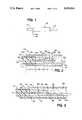
- FIG. 2is a partial cross-sectional view of the present invention, as viewed through line 2--2 of FIG. 1.
- FIG. 3is a cross-sectional view of an alternate embodiment of the present invention.
- FIG. 4is a cross-sectional view of another alternate embodiment of the present invention.
- FIG. 5is a general view of a plurality of modules of the present invention, connected in series.
- FIG. 6is a cross-sectional view of another embodiment of the present invention, illustrating a bias feedthrough.
- FIG. 1shows a general external view of a hermetic module 10 of the present invention in a typical configuration integrated with a coaxial cable for microwave transmission.
- Hermetic module 10contains at least one electronic component therein, and is joined at one end to coaxial cable 12.
- Hermetic module 10may also be connected at its other end to a second coaxial cable 13. It is likely that the size of the electronic components within module 10 may require module 10 to have an outer diameter slightly larger than that of the coaxial cable.
- Metallurgical joints 14a and 14bjoin the module 10 to coaxial cables 12 and 13 and form a hermetic seal.
- FIG. 2is a partial cross-sectional view of the module and cables in FIG. 1, and illustrates the end of the coaxial cable 12 inserted into one end of hermetic module 10.
- Hermetic module 10 and coaxial cable 12form a connectorless joint.
- On the outer surface of module 10is a generally tubular cover 16.
- the cover 16serves as a housing for the other components in the module.
- Disposed around the interior surface of the cover 16is the body 18.
- Body 18is of a conductive material and forms a recess in the form of an axial bore in registration with the opening of the cover 16, and forms with the cover 16 an inner cavity 36.
- Inner cavity 36contains the electronic components in the module, as will be explained below.
- the metallurgical joint 14ainterconnects the cover 16 and body 18 to form a hermetic seal around the inner cavity 36.
- the metallurgical joint 14binterconnects the body 18 to cable 12. (Another metallurgical joint similarly connects body 18 to cable 13 on the other end of module 10, not shown.)
- Bead 20forms a hermetic seal for cavity 36, as described below.
- a conductor member 22Embedded within the glass bead 20, along the central axis of the module 10, is a conductor member 22.
- a female receptacle 24having a center recess 26, which is adapted to receive the center conductor 30 of the coaxial cable 12, as will be explained below.
- a terminal end 28At the opposite end of conductor member 22 is a terminal end 28.
- the glass bead 20is fused to the surface of conductor member 22 and the axial bore in body 18 to form a restraining interface and hermetic seal.
- the conductor member 22forms inward-facing shoulders 23 against the ends of the glass bead 20.
- the glass bead 20engages the inward-facing shoulders to restrain the conductor member 22 against movement along the axis of the module 10 when any part of the module is subjected to mechanical stress.
- the coaxial cable 12 which is inserted into the end of the module 10may be of any type of coaxial cable.
- a coaxial cable 12includes a center conductor 30, an outer conductor 32, and an insulating layer 34 disposed between the center conductor 30 and the outer conductor 32.
- outer conductor 32 and insulating layer 34 of the coaxial cable 12are removed in well-known manner to expose a length of the center conductor 30.
- Coaxial cable 12is inserted into the body of the module 10, and is engaged by the axial bore in the body 18, so that outer conductor 32 is in electrical contact with body 18.
- center conductor 30The exposed length of center conductor 30 at the end of coaxial cable 12 fits into the female receptacle 24 when the coaxial cable 12 is inserted into the body 18 of the module 10.
- the center conductor 30may be tapered at its end, as shown, to facilitate easy insertion into the female receptacle 24.
- the axial bore in the body 18is preferably formed in three regions, designated in FIG. 2 as A, B, and C, each having a different inner diameter and forming shoulders therebetween.
- Region Athe outermost portion of the axial bore, is of a diameter just large enough to accommodate the body of the coaxial cable 12 and form a contact with the outer conductor 32, as shown.
- Region Bhas a slightly smaller inner diameter so as to form a shoulder between region A and region B. This shoulder acts to limit the extent of insertion of coaxial cable 12 into module 10.
- Region Chas a still smaller inner diameter and provides a surface for the hermetic seal of the glass bead 20.
- module 10 of the present inventionIn many situations it is desirable to design module 10 of the present invention to have a known and predetermined characteristic impedance, so that a circuit designer using the module may take the impedance of the joint itself into account in designing a circuit.
- the characteristic impedance of the joint between the coaxial cable and module 10is dependent on the dimensions of the axial bore in body 18 in the area around the female receptacle 24 of the conductor member 22, shown as region B in FIG. 2.
- region Bthe mated female receptacle outside diameter and corresponding body inside diameter form an air dielectric coaxial transmission line having a predetermined impedance.
- the module 10may be designed to have a predetermined characteristic impedance. This predetermined impedance can be taken into account when the module 10 is incorporated in a microwave circuit.
- module 10Interior of module 10 is a cavity 36 defined by the cover 16 and body 18, in which electronic components, such as that shown by 38 in FIG. 2, may be disposed. Each electronic component may be operatively connected to the terminal end 28 of conductor member 22 by wire bonding 40, or other means.
- the electronic componentsare preferably designed to have a first surface having terminals for inputs and outputs, and a second surface opposite the first surface which is intended to be connected to ground.
- body 18is conductive, and typically forms a connection with the outer conductor 32 of the coaxial cable 12 (which typically is the connection to ground)
- the components within the inner cavity 36are arranged so that their surfaces associated with ground are attached to the body member 18 while their functional surfaces may be readily connected to the terminal end 28 of conductor member 22.
- the componentsmay be connected in a functional closed circuit fashion between the center conductors 32 of the coaxial cables 12 and 13.
- FIGS. 3 and 4illustrate variations of the present invention having multiple electronic components within the cavity 36 to perform various functions.
- the cavity 36contains a number of electronic components 38, 42, and 44, arranged in series and connected by wire bonding 40, to form an amplifier.
- parts 38 and 44are resistors and component 42 is a monolithic amplifier device.
- FIG. 4is shown a hermetic module containing integrated circuit components, such as capacitor 46, monolithic amplifier 42, and a capacitor 48 in combination with an inductor 50.
- the various componentsare preferably connected with wire bonding 40, although within the scope of the invention the components inside the module may be connected together by any known technique.
- the joint between the coaxial cable 12 and module 10 shown in FIG. 2may be duplicated at the other end of the module 10 as well, so that the module 10 will form a connectorless joint with coaxial cable at both ends.
- FIG. 5is a general view of a multiple connection of two modules 10 and 10a, showing how different modules may be combined for specific purposes.
- Various modules 10may be manufactured having different configurations and combinations of electronic components therein, and then combined as necessary for the specific application.
- Each modulemay be hermetically sealed with the structure shown in FIG. 2 arranged symmetrically at both ends of the module 10. Such a module would thus accept coaxial cable 12 from both ends.
- the electronic components inside the cavity 36 of the hermetic module 10will be active components; that is, they will require an external source of voltage or current in order to operate.
- This external source of poweris distinguished from the signal which enters the hermetic module 10 through the coaxial cable 12 and typically through the center conductor 30 of the coaxial cable 12.
- the external voltage or currentmay be used as a power source for the active components, such as an operational amplifier, or as a source of performance control. In most cases the voltage or current must be supplied via a separate conductor member, which must also form a hermetic seal with the inner cavity 36.
- FIG. 6shows an alternate embodiment 10' of the present invention, having a "bias feedthrough" means in addition to the recess for accepting the coaxial cable 12.
- the bias feedthroughincludes a second conductor member 100, having a first end 102 disposed external of the module 10', and a second end 104, which is disposed within the cavity 36'.
- the first end 102may be of any particular shape to accommodate any type of external connection.
- Second end 104may be connected, by a wire bond 106 or other means, to any number of active components such as 108 inside cavity 36'.
- Second conductor member 100 of the bias feedthroughis, like the conductor member 22 for the coaxial cable, hermetically sealed within a recess of the body member 18' by second sealing member 110.
- Second sealing member 110is made of a material such as ceramic or glass, and seals the cavity 36' between the second conductor member 100 and the body member 18'.
- the second conductor member 100may, but need not, be captivated.
- the connectorless joint formed between the module 10 and the coaxial cable 12provides an interface which allows the electronic components inside the module 10 to be hermetically sealed within the module, without adding the excess weight or requiring the extra space associated with discrete microwave connectors. Also, the invention provides an interface between the coaxial cable and the electronic components in the module which may be easily modified by replacing the module when an upgrade of a system is required.
Landscapes
- Coupling Device And Connection With Printed Circuit (AREA)
Abstract
Description
Claims (6)
Priority Applications (3)
| Application Number | Priority Date | Filing Date | Title |
|---|---|---|---|
| US07/526,345US5070314A (en) | 1990-05-21 | 1990-05-21 | Hermetic module containing microwave component |
| EP19910304431EP0458532A3 (en) | 1990-05-21 | 1991-05-17 | Hermetic module containing microwave component |
| JP3142679AJPH04229579A (en) | 1990-05-21 | 1991-05-20 | Module for housing electronic element |
Applications Claiming Priority (1)
| Application Number | Priority Date | Filing Date | Title |
|---|---|---|---|
| US07/526,345US5070314A (en) | 1990-05-21 | 1990-05-21 | Hermetic module containing microwave component |
Publications (1)
| Publication Number | Publication Date |
|---|---|
| US5070314Atrue US5070314A (en) | 1991-12-03 |
Family
ID=24096957
Family Applications (1)
| Application Number | Title | Priority Date | Filing Date |
|---|---|---|---|
| US07/526,345Expired - Fee RelatedUS5070314A (en) | 1990-05-21 | 1990-05-21 | Hermetic module containing microwave component |
Country Status (3)
| Country | Link |
|---|---|
| US (1) | US5070314A (en) |
| EP (1) | EP0458532A3 (en) |
| JP (1) | JPH04229579A (en) |
Cited By (6)
| Publication number | Priority date | Publication date | Assignee | Title |
|---|---|---|---|---|
| US5217392A (en)* | 1992-11-13 | 1993-06-08 | The Whitaker Corporation | Coaxial cable-to-cable splice connector |
| US20030046493A1 (en)* | 2001-08-31 | 2003-03-06 | Coulson Richard L. | Hardware updated metadata for non-volatile mass storage cache |
| US6725342B1 (en) | 2000-09-26 | 2004-04-20 | Intel Corporation | Non-volatile mass storage cache coherency apparatus |
| US6785767B2 (en) | 2000-12-26 | 2004-08-31 | Intel Corporation | Hybrid mass storage system and method with two different types of storage medium |
| US20050024837A1 (en)* | 2003-07-31 | 2005-02-03 | Youker Nick A. | Integrated electromagnetic interference filters and feedthroughs |
| CN104701379A (en)* | 2013-12-10 | 2015-06-10 | 赛米控电子股份有限公司 | Power semiconductor device |
Families Citing this family (1)
| Publication number | Priority date | Publication date | Assignee | Title |
|---|---|---|---|---|
| DE202005015509U1 (en)* | 2005-10-04 | 2005-12-08 | Rosenberger Hochfrequenztechnik Gmbh & Co. Kg | Coaxial cable connector has inner and outer contacts that provide high performance electrical characteristics |
Citations (4)
| Publication number | Priority date | Publication date | Assignee | Title |
|---|---|---|---|---|
| US2449073A (en)* | 1945-08-06 | 1948-09-14 | John D Johannesen | Coaxial line connector |
| US4161704A (en)* | 1977-01-21 | 1979-07-17 | Uniform Tubes, Inc. | Coaxial cable and method of making the same |
| US4266207A (en)* | 1979-11-07 | 1981-05-05 | Uti Corporation | Coaxial cable band-pass filter |
| US4486726A (en)* | 1982-10-07 | 1984-12-04 | Uti Corporation | Joint between coaxial cable and microwave component |
Family Cites Families (1)
| Publication number | Priority date | Publication date | Assignee | Title |
|---|---|---|---|---|
| US2758148A (en)* | 1950-03-08 | 1956-08-07 | Int Standard Electric Corp | Coaxial cable joints |
- 1990
- 1990-05-21USUS07/526,345patent/US5070314A/ennot_activeExpired - Fee Related
- 1991
- 1991-05-17EPEP19910304431patent/EP0458532A3/ennot_activeWithdrawn
- 1991-05-20JPJP3142679Apatent/JPH04229579A/ennot_activeWithdrawn
Patent Citations (4)
| Publication number | Priority date | Publication date | Assignee | Title |
|---|---|---|---|---|
| US2449073A (en)* | 1945-08-06 | 1948-09-14 | John D Johannesen | Coaxial line connector |
| US4161704A (en)* | 1977-01-21 | 1979-07-17 | Uniform Tubes, Inc. | Coaxial cable and method of making the same |
| US4266207A (en)* | 1979-11-07 | 1981-05-05 | Uti Corporation | Coaxial cable band-pass filter |
| US4486726A (en)* | 1982-10-07 | 1984-12-04 | Uti Corporation | Joint between coaxial cable and microwave component |
Cited By (15)
| Publication number | Priority date | Publication date | Assignee | Title |
|---|---|---|---|---|
| US5217392A (en)* | 1992-11-13 | 1993-06-08 | The Whitaker Corporation | Coaxial cable-to-cable splice connector |
| US6941423B2 (en) | 2000-09-26 | 2005-09-06 | Intel Corporation | Non-volatile mass storage cache coherency apparatus |
| US6725342B1 (en) | 2000-09-26 | 2004-04-20 | Intel Corporation | Non-volatile mass storage cache coherency apparatus |
| US20040162950A1 (en)* | 2000-09-26 | 2004-08-19 | Coulson Richard L. | Non-volatile mass storage cache coherency apparatus |
| US7308531B2 (en) | 2000-12-26 | 2007-12-11 | Intel Corporation | Hybrid mass storage system and method |
| US20040225835A1 (en)* | 2000-12-26 | 2004-11-11 | Coulson Richard L. | Hybrid mass storage system and method |
| US6785767B2 (en) | 2000-12-26 | 2004-08-31 | Intel Corporation | Hybrid mass storage system and method with two different types of storage medium |
| US7275135B2 (en) | 2001-08-31 | 2007-09-25 | Intel Corporation | Hardware updated metadata for non-volatile mass storage cache |
| US20030046493A1 (en)* | 2001-08-31 | 2003-03-06 | Coulson Richard L. | Hardware updated metadata for non-volatile mass storage cache |
| US20050024837A1 (en)* | 2003-07-31 | 2005-02-03 | Youker Nick A. | Integrated electromagnetic interference filters and feedthroughs |
| US7719854B2 (en)* | 2003-07-31 | 2010-05-18 | Cardiac Pacemakers, Inc. | Integrated electromagnetic interference filters and feedthroughs |
| CN104701379A (en)* | 2013-12-10 | 2015-06-10 | 赛米控电子股份有限公司 | Power semiconductor device |
| US20150163914A1 (en)* | 2013-12-10 | 2015-06-11 | Semikron Elektronik Gmbh & Co., Kg | Power semiconductor device |
| US9462695B2 (en)* | 2013-12-10 | 2016-10-04 | Semikron Elektronik Gmbh & Co., Kg | Power semiconductor device |
| CN104701379B (en)* | 2013-12-10 | 2019-03-01 | 赛米控电子股份有限公司 | Power semiconductor arrangement |
Also Published As
| Publication number | Publication date |
|---|---|
| JPH04229579A (en) | 1992-08-19 |
| EP0458532A2 (en) | 1991-11-27 |
| EP0458532A3 (en) | 1992-09-16 |
Similar Documents
| Publication | Publication Date | Title |
|---|---|---|
| US4724409A (en) | Microwave circuit package connector | |
| US4957456A (en) | Self-aligning RF push-on connector | |
| US5318459A (en) | Ruggedized, sealed quick disconnect electrical coupler | |
| EP0733274B1 (en) | Coaxial connector with impedance control | |
| EP0769828B1 (en) | Fully insulated, fully shielded electrical connector arrangement | |
| US4925403A (en) | Coaxial transmission medium connector | |
| US6389903B1 (en) | Pressure-detecting device coupling member with interchangeable connector part | |
| US6778044B2 (en) | Coaxial line plug-in connection with integrated galvanic separation | |
| EP0241738A2 (en) | Databus coupler electrical connector | |
| US10403995B2 (en) | Electrical connector, electronic component, and assembly method | |
| US5070314A (en) | Hermetic module containing microwave component | |
| EP1072061A1 (en) | Control impedance rf pin for extending compressible button interconnect contact distance | |
| US4975065A (en) | Microwave circuit module connector | |
| US20020086584A1 (en) | Electrical connector having built-in electrical devices | |
| US20210166842A1 (en) | Arrangement For Attaching An Insulator Sleeve To An Electrical Conductor | |
| EP4239809A2 (en) | Electric apparatus with electric connection and protection function, connector and fabricating method thereof | |
| US20060154521A1 (en) | Method for sealing partition bushing connector coaxial contacts, adapted coaxial contact and resulting connector | |
| JP2002523884A (en) | Outer filter box | |
| EP0503380B1 (en) | Electrical connector system | |
| JPS6010082Y2 (en) | Microwave equipment connection structure | |
| US6245993B1 (en) | Electronic assembly having shielding and strain-relief member | |
| CN1049072C (en) | How to assemble the cable connector | |
| WO2023166283A1 (en) | Electrical feedthrough, vacuum apparatus and method for assembly | |
| KR102244970B1 (en) | Adapter for mi cables used in nuclear fusion device | |
| JPH0432512B2 (en) |
Legal Events
| Date | Code | Title | Description |
|---|---|---|---|
| AS | Assignment | Owner name:UTI CORPORATION, A CORP OF PA, PENNSYLVANIA Free format text:ASSIGNMENT OF ASSIGNORS INTEREST.;ASSIGNOR:DECKER, FRANK;REEL/FRAME:005350/0818 Effective date:19900516 | |
| FEPP | Fee payment procedure | Free format text:PAYOR NUMBER ASSIGNED (ORIGINAL EVENT CODE: ASPN); ENTITY STATUS OF PATENT OWNER: SMALL ENTITY | |
| FPAY | Fee payment | Year of fee payment:4 | |
| REMI | Maintenance fee reminder mailed | ||
| LAPS | Lapse for failure to pay maintenance fees | ||
| FP | Lapsed due to failure to pay maintenance fee | Effective date:19991203 | |
| AS | Assignment | Owner name:CREDIT SUISSE FIRST BOSTON, ACTING THROUGH ITS CAY Free format text:SECURITY INTEREST;ASSIGNOR:UTI CORPORATION;REEL/FRAME:015056/0602 Effective date:20040630 | |
| AS | Assignment | Owner name:ACCELLENT CORP., MASSACHUSETTS Free format text:RELEASE OF PATENT SECURITY AGREEMENT;ASSIGNOR:CREDIT SUISSE, CAYMAN ISLANDS BRANCH, (FORMERLY KNOWN AS CREDIT SUISSE FIRST BOSTON, ACTING THROUGH ITS CAYMAN ISLANDS BRANCH) AS COLLATERAL AGENT;REEL/FRAME:017125/0505 Effective date:20051122 Owner name:MEDICAL DEVICE MANUFACTURING, INC., MASSACHUSETTS Free format text:RELEASE OF PATENT SECURITY AGREEMENT;ASSIGNOR:CREDIT SUISSE, CAYMAN ISLANDS BRANCH, (FORMERLY KNOWN AS CREDIT SUISSE FIRST BOSTON, ACTING THROUGH ITS CAYMAN ISLANDS BRANCH) AS COLLATERAL AGENT;REEL/FRAME:017125/0505 Effective date:20051122 Owner name:UTI CORPORATION, MASSACHUSETTS Free format text:RELEASE OF PATENT SECURITY AGREEMENT;ASSIGNOR:CREDIT SUISSE, CAYMAN ISLANDS BRANCH, (FORMERLY KNOWN AS CREDIT SUISSE FIRST BOSTON, ACTING THROUGH ITS CAYMAN ISLANDS BRANCH) AS COLLATERAL AGENT;REEL/FRAME:017125/0505 Effective date:20051122 Owner name:MEDSOURCE TRENTON, INC., MASSACHUSETTS Free format text:RELEASE OF PATENT SECURITY AGREEMENT;ASSIGNOR:CREDIT SUISSE, CAYMAN ISLANDS BRANCH, (FORMERLY KNOWN AS CREDIT SUISSE FIRST BOSTON, ACTING THROUGH ITS CAYMAN ISLANDS BRANCH) AS COLLATERAL AGENT;REEL/FRAME:017125/0505 Effective date:20051122 Owner name:SPECTRUM MANUFACTURING, INC., MASSACHUSETTS Free format text:RELEASE OF PATENT SECURITY AGREEMENT;ASSIGNOR:CREDIT SUISSE, CAYMAN ISLANDS BRANCH, (FORMERLY KNOWN AS CREDIT SUISSE FIRST BOSTON, ACTING THROUGH ITS CAYMAN ISLANDS BRANCH) AS COLLATERAL AGENT;REEL/FRAME:017125/0505 Effective date:20051122 Owner name:NOBLE-MET, LTD., MASSACHUSETTS Free format text:RELEASE OF PATENT SECURITY AGREEMENT;ASSIGNOR:CREDIT SUISSE, CAYMAN ISLANDS BRANCH, (FORMERLY KNOWN AS CREDIT SUISSE FIRST BOSTON, ACTING THROUGH ITS CAYMAN ISLANDS BRANCH) AS COLLATERAL AGENT;REEL/FRAME:017125/0505 Effective date:20051122 Owner name:CYCAM, INC., MASSACHUSETTS Free format text:RELEASE OF PATENT SECURITY AGREEMENT;ASSIGNOR:CREDIT SUISSE, CAYMAN ISLANDS BRANCH, (FORMERLY KNOWN AS CREDIT SUISSE FIRST BOSTON, ACTING THROUGH ITS CAYMAN ISLANDS BRANCH) AS COLLATERAL AGENT;REEL/FRAME:017125/0505 Effective date:20051122 Owner name:MEDSOURCE TECHNOLOGIES, INC., MASSACHUSETTS Free format text:RELEASE OF PATENT SECURITY AGREEMENT;ASSIGNOR:CREDIT SUISSE, CAYMAN ISLANDS BRANCH, (FORMERLY KNOWN AS CREDIT SUISSE FIRST BOSTON, ACTING THROUGH ITS CAYMAN ISLANDS BRANCH) AS COLLATERAL AGENT;REEL/FRAME:017125/0505 Effective date:20051122 | |
| AS | Assignment | Owner name:JPMORGAN CHASE BANK N.A., AS ADMINISTRATIVE AGENT, Free format text:GRANT OF SECURITY INTEREST IN PATENTS;ASSIGNOR:UTI CORPORATION;REEL/FRAME:017136/0165 Effective date:20051122 | |
| AS | Assignment | Owner name:ACCELLENT INC.,MASSACHUSETTS Free format text:TERMINATION AND RELEASE OF SECURITY INTEREST IN PATENT RIGHTS;ASSIGNOR:JPMORGAN CHASE BANK, N.A., AS ADMINISTRATIVE AGENT;REEL/FRAME:023928/0409 Effective date:20100129 Owner name:UTI CORPORATION (NOW UTI HOLDINGS, LLC),PENNSYLVAN Free format text:TERMINATION AND RELEASE OF SECURITY INTEREST IN PATENT RIGHTS;ASSIGNOR:JPMORGAN CHASE BANK, N.A., AS ADMINISTRATIVE AGENT;REEL/FRAME:023928/0409 Effective date:20100129 Owner name:MEDSOURCE TECHNOLOGIES, LLC,NEW YORK Free format text:TERMINATION AND RELEASE OF SECURITY INTEREST IN PATENT RIGHTS;ASSIGNOR:JPMORGAN CHASE BANK, N.A., AS ADMINISTRATIVE AGENT;REEL/FRAME:023928/0409 Effective date:20100129 Owner name:MEDSOURCE TRENTON, INC. (NOW MEDSOURCE TRENTON LLC Free format text:TERMINATION AND RELEASE OF SECURITY INTEREST IN PATENT RIGHTS;ASSIGNOR:JPMORGAN CHASE BANK, N.A., AS ADMINISTRATIVE AGENT;REEL/FRAME:023928/0409 Effective date:20100129 Owner name:MEDSOURCE TECHNOLOGIES PITTSBURGH, INC.,PENNSYLVAN Free format text:TERMINATION AND RELEASE OF SECURITY INTEREST IN PATENT RIGHTS;ASSIGNOR:JPMORGAN CHASE BANK, N.A., AS ADMINISTRATIVE AGENT;REEL/FRAME:023928/0409 Effective date:20100129 Owner name:MEDSOURCE TECHNOLOGIES, NEWTON INC.,MASSACHUSETTS Free format text:TERMINATION AND RELEASE OF SECURITY INTEREST IN PATENT RIGHTS;ASSIGNOR:JPMORGAN CHASE BANK, N.A., AS ADMINISTRATIVE AGENT;REEL/FRAME:023928/0409 Effective date:20100129 Owner name:THERMAT ACQUISITION CORP. (NOW THERMAT ACQUISITION Free format text:TERMINATION AND RELEASE OF SECURITY INTEREST IN PATENT RIGHTS;ASSIGNOR:JPMORGAN CHASE BANK, N.A., AS ADMINISTRATIVE AGENT;REEL/FRAME:023928/0409 Effective date:20100129 Owner name:NOBLE-MET, LTD. (NOW NOBLE-MET LLC),VIRGINIA Free format text:TERMINATION AND RELEASE OF SECURITY INTEREST IN PATENT RIGHTS;ASSIGNOR:JPMORGAN CHASE BANK, N.A., AS ADMINISTRATIVE AGENT;REEL/FRAME:023928/0409 Effective date:20100129 Owner name:SPECTRUM MANUFACTURING, INC.,ILLINOIS Free format text:TERMINATION AND RELEASE OF SECURITY INTEREST IN PATENT RIGHTS;ASSIGNOR:JPMORGAN CHASE BANK, N.A., AS ADMINISTRATIVE AGENT;REEL/FRAME:023928/0409 Effective date:20100129 Owner name:PORTLYN, LLC,NEW HAMPSHIRE Free format text:TERMINATION AND RELEASE OF SECURITY INTEREST IN PATENT RIGHTS;ASSIGNOR:JPMORGAN CHASE BANK, N.A., AS ADMINISTRATIVE AGENT;REEL/FRAME:023928/0409 Effective date:20100129 Owner name:DANFORTH BIOMEDICAL, INC. (NOW MEDSOURCE TECHNOLOG Free format text:TERMINATION AND RELEASE OF SECURITY INTEREST IN PATENT RIGHTS;ASSIGNOR:JPMORGAN CHASE BANK, N.A., AS ADMINISTRATIVE AGENT;REEL/FRAME:023928/0409 Effective date:20100129 Owner name:ACT MEDICAL, INC. (NOW MEDSOURCE TECHNOLOGIES, NEW Free format text:TERMINATION AND RELEASE OF SECURITY INTEREST IN PATENT RIGHTS;ASSIGNOR:JPMORGAN CHASE BANK, N.A., AS ADMINISTRATIVE AGENT;REEL/FRAME:023928/0409 Effective date:20100129 Owner name:CYCAM, INC. (NOW MEDSOURCE TECHNOLOGIES PITTSBURGH Free format text:TERMINATION AND RELEASE OF SECURITY INTEREST IN PATENT RIGHTS;ASSIGNOR:JPMORGAN CHASE BANK, N.A., AS ADMINISTRATIVE AGENT;REEL/FRAME:023928/0409 Effective date:20100129 Owner name:G&D, INC. D/B/A STAR GUIDE CORPORATION (NOW G&D, L Free format text:TERMINATION AND RELEASE OF SECURITY INTEREST IN PATENT RIGHTS;ASSIGNOR:JPMORGAN CHASE BANK, N.A., AS ADMINISTRATIVE AGENT;REEL/FRAME:023928/0409 Effective date:20100129 Owner name:ACCELLENT INC., MASSACHUSETTS Free format text:TERMINATION AND RELEASE OF SECURITY INTEREST IN PATENT RIGHTS;ASSIGNOR:JPMORGAN CHASE BANK, N.A., AS ADMINISTRATIVE AGENT;REEL/FRAME:023928/0409 Effective date:20100129 Owner name:UTI CORPORATION (NOW UTI HOLDINGS, LLC), PENNSYLVA Free format text:TERMINATION AND RELEASE OF SECURITY INTEREST IN PATENT RIGHTS;ASSIGNOR:JPMORGAN CHASE BANK, N.A., AS ADMINISTRATIVE AGENT;REEL/FRAME:023928/0409 Effective date:20100129 Owner name:MEDSOURCE TECHNOLOGIES, LLC, NEW YORK Free format text:TERMINATION AND RELEASE OF SECURITY INTEREST IN PATENT RIGHTS;ASSIGNOR:JPMORGAN CHASE BANK, N.A., AS ADMINISTRATIVE AGENT;REEL/FRAME:023928/0409 Effective date:20100129 Owner name:MEDSOURCE TECHNOLOGIES PITTSBURGH, INC., PENNSYLVA Free format text:TERMINATION AND RELEASE OF SECURITY INTEREST IN PATENT RIGHTS;ASSIGNOR:JPMORGAN CHASE BANK, N.A., AS ADMINISTRATIVE AGENT;REEL/FRAME:023928/0409 Effective date:20100129 Owner name:MEDSOURCE TECHNOLOGIES, NEWTON INC., MASSACHUSETTS Free format text:TERMINATION AND RELEASE OF SECURITY INTEREST IN PATENT RIGHTS;ASSIGNOR:JPMORGAN CHASE BANK, N.A., AS ADMINISTRATIVE AGENT;REEL/FRAME:023928/0409 Effective date:20100129 Owner name:NOBLE-MET, LTD. (NOW NOBLE-MET LLC), VIRGINIA Free format text:TERMINATION AND RELEASE OF SECURITY INTEREST IN PATENT RIGHTS;ASSIGNOR:JPMORGAN CHASE BANK, N.A., AS ADMINISTRATIVE AGENT;REEL/FRAME:023928/0409 Effective date:20100129 Owner name:SPECTRUM MANUFACTURING, INC., ILLINOIS Free format text:TERMINATION AND RELEASE OF SECURITY INTEREST IN PATENT RIGHTS;ASSIGNOR:JPMORGAN CHASE BANK, N.A., AS ADMINISTRATIVE AGENT;REEL/FRAME:023928/0409 Effective date:20100129 Owner name:PORTLYN, LLC, NEW HAMPSHIRE Free format text:TERMINATION AND RELEASE OF SECURITY INTEREST IN PATENT RIGHTS;ASSIGNOR:JPMORGAN CHASE BANK, N.A., AS ADMINISTRATIVE AGENT;REEL/FRAME:023928/0409 Effective date:20100129 | |
| STCH | Information on status: patent discontinuation | Free format text:PATENT EXPIRED DUE TO NONPAYMENT OF MAINTENANCE FEES UNDER 37 CFR 1.362 |