US5070267A - Low-noise electric motor assembly for automotive blower - Google Patents
Low-noise electric motor assembly for automotive blowerDownload PDFInfo
- Publication number
- US5070267A US5070267AUS07/482,938US48293890AUS5070267AUS 5070267 AUS5070267 AUS 5070267AUS 48293890 AUS48293890 AUS 48293890AUS 5070267 AUS5070267 AUS 5070267A
- Authority
- US
- United States
- Prior art keywords
- casing
- pulse width
- motor assembly
- electric motor
- width modulating
- Prior art date
- Legal status (The legal status is an assumption and is not a legal conclusion. Google has not performed a legal analysis and makes no representation as to the accuracy of the status listed.)
- Expired - Lifetime
Links
Images

Classifications
- B—PERFORMING OPERATIONS; TRANSPORTING
- B60—VEHICLES IN GENERAL
- B60H—ARRANGEMENTS OF HEATING, COOLING, VENTILATING OR OTHER AIR-TREATING DEVICES SPECIALLY ADAPTED FOR PASSENGER OR GOODS SPACES OF VEHICLES
- B60H1/00—Heating, cooling or ventilating [HVAC] devices
- B60H1/00642—Control systems or circuits; Control members or indication devices for heating, cooling or ventilating devices
- B60H1/00814—Control systems or circuits characterised by their output, for controlling particular components of the heating, cooling or ventilating installation
- B60H1/00821—Control systems or circuits characterised by their output, for controlling particular components of the heating, cooling or ventilating installation the components being ventilating, air admitting or air distributing devices
- B60H1/00828—Ventilators, e.g. speed control
- H—ELECTRICITY
- H02—GENERATION; CONVERSION OR DISTRIBUTION OF ELECTRIC POWER
- H02K—DYNAMO-ELECTRIC MACHINES
- H02K11/00—Structural association of dynamo-electric machines with electric components or with devices for shielding, monitoring or protection
- H02K11/01—Structural association of dynamo-electric machines with electric components or with devices for shielding, monitoring or protection for shielding from electromagnetic fields, i.e. structural association with shields
- H02K11/014—Shields associated with stationary parts, e.g. stator cores
- H02K11/0141—Shields associated with casings, enclosures or brackets
- H—ELECTRICITY
- H02—GENERATION; CONVERSION OR DISTRIBUTION OF ELECTRIC POWER
- H02K—DYNAMO-ELECTRIC MACHINES
- H02K11/00—Structural association of dynamo-electric machines with electric components or with devices for shielding, monitoring or protection
- H02K11/02—Structural association of dynamo-electric machines with electric components or with devices for shielding, monitoring or protection for suppression of electromagnetic interference
- H—ELECTRICITY
- H02—GENERATION; CONVERSION OR DISTRIBUTION OF ELECTRIC POWER
- H02K—DYNAMO-ELECTRIC MACHINES
- H02K11/00—Structural association of dynamo-electric machines with electric components or with devices for shielding, monitoring or protection
- H02K11/04—Structural association of dynamo-electric machines with electric components or with devices for shielding, monitoring or protection for rectification
- H02K11/049—Rectifiers associated with stationary parts, e.g. stator cores
- H02K11/05—Rectifiers associated with casings, enclosures or brackets
- H—ELECTRICITY
- H02—GENERATION; CONVERSION OR DISTRIBUTION OF ELECTRIC POWER
- H02K—DYNAMO-ELECTRIC MACHINES
- H02K23/00—DC commutator motors or generators having mechanical commutator; Universal AC/DC commutator motors
- H02K23/66—Structural association with auxiliary electric devices influencing the characteristic of, or controlling, the machine, e.g. with impedances or switches
- H—ELECTRICITY
- H02—GENERATION; CONVERSION OR DISTRIBUTION OF ELECTRIC POWER
- H02K—DYNAMO-ELECTRIC MACHINES
- H02K9/00—Arrangements for cooling or ventilating
- H02K9/02—Arrangements for cooling or ventilating by ambient air flowing through the machine
- H02K9/04—Arrangements for cooling or ventilating by ambient air flowing through the machine having means for generating a flow of cooling medium
- H02K9/06—Arrangements for cooling or ventilating by ambient air flowing through the machine having means for generating a flow of cooling medium with fans or impellers driven by the machine shaft
Definitions
- the present inventionrelates in general to electric motors for driving an automotive blower, and more particularly, to the electric motors of a low-noise type. More specifically, our present invention is concerned with a low-noise motor assembly for an automotive blower, being installed therein a rotation speed controller including a pulse width modulating device.
- An automotive blowercomprises generally a fan, an electric motor for driving the fan and a speed controller for controlling the rotational speed of the electric motor.
- speed controllers hitherto employedthere is a type which uses a power transistor for functional and commercial superiority, in which the control of the rotation speed can be made in a stepless manner.
- the transistoris mounted to a heat sink which is located in a well-ventilated area.
- the heat sinkis exposed to an air passage defined in an air distributing unit of the air conditioner.
- an electric motor assemblyfor driving an air blower.
- the assemblycomprises a casing of metal, the casing having opposed open ends closed by respective covers of metal; a rotation shaft rotatably disposed in the casing, the rotation shaft having one end exposed to the outside through an opening formed in one of the covers, the one end being adapted to connect to a fan of the air blower; a plurality of magnets installed in the casing and circumferentially surrounding the rotation axis; an armature mounted to the rotation shaft to rotate therewith; a commutator mounted to the rotation shaft and electrically connected with the armature; brushes operatively contacting with the commutator and supported by the casing; an electric power feeding means for feeding the brushes with an electric power; and a pulse width modulating device electrically connected with the power feeding means for modulating the electric power by means of a pulse width modulation method, the pulse width modulating device being installed in the casing.
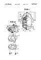
- FIG. 1is a half-sectional view of an electric motor assembly according to the present invention
- FIG. 2is an exploded view showing a metal base plate, a radiating plate and a brush base, which are installed in the electric motor assembly of the present invention
- FIG. 3is an electric circuit employed in the electric motor assembly of the invention.
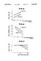
- FIG. 4is a graph showing the characteristics of both the electric motor assembly of the present invention and a conventional electric motor assembly, in terms of a relationship between a voltage applied to the motor assembly and an electric power loss;
- FIG. 5is a graph showing the characteristics of the present invention and the conventional motor assembly in terms of a relationship between the air blowing capacity and the noise level in an air distributing unit;
- FIG. 6is a graph showing the characteristics of the present invention and the conventional motor assembly in terms of a relationship between the air blowing capacity and the static pressure in the air distributing unit;
- FIG. 7is a graph showing the characteristics of the present invention and a reference example wherein a pulse width modulating device is arranged outside of the electric motor assembly, in terms of a relationship between the intensity of input radio signal and the output level.
- FIG. 1 of the accompanying drawingsthere is shown an electric motor assembly according to the present invention, which is equipped with a fan of an air blower installed in an air distributing unit of an automotive air conditioner.
- the air distributing unitcomprises generally an indoor air introducing duct, an outdoor air introducing duct, an air mixing chamber in which a switch door is arranged to fully and partly open and close these two introducing ducts and an air outlet duct from which the mixed air in the mixing chamber is introduced to an air conditioning device.
- the air thus conditioned by the air conditioning deviceis blown into a passenger room of the motor vehicle.
- the electric motor assemblycomprises a cylindrical casing 3 constructed 0 of an electrically condutive material, such as metal or the like.
- a plurality of magnets 4are installed in the casing 3 in a manner to circumferentially surround the center axis of the casing 3.
- a rotation shaft 2is rotatably and concentrically disposed in the casing 3 and has an armature 5 mounted thereto.
- Designated by numerals 13a and 13bare bearings for smoothing the rotation of the rotation shaft 2 relative to the casing 3.
- a commutator 7is fixed to the rotation shaft 2, from which lead wires extend to a multi-turned coil 14 of the armature 5.
- Brushes 6are supported on a brush base 8 of a suitable plastic, which brushes are in contact with the commutator 7.
- the brushes 6are slidably received in respective brush holders 15 which are mounted on the brush base 8. Each brush 6 is biased toward the commutator 7 by a spring 16.
- the casing 3has axially opposed open ends which are respectively closed by stepped conical covers of metal 3a and 3b.
- the cover 3bhas a center opening (no numeral) through which one end of the rotation shaft 2 is exposed to the outside of the casing 3.
- Each cover 3a or 3bis formed with a ventilation opening 9a or 9b.
- the fan 1is coaxially fixed to the exposed end of the rotation shaft 2 to rotate therewith. It is to be noted that the fan 1 is so constructed that upon rotation thereof, a negative pressure area is produced between the back side of the fan 1 and the cover 3b.
- Designated by numeral 17 in FIG. 1is a part of an air distributing unit, which has a recess 18 into which the electric motor assembly is tightly disposed having the fan 1 exposed to the air passage of the air distributing unit 17.
- the recess 18has at its bottom portion an opening (no numeral) from which a ventilation pipe 19 extends to a downstream part of the air passage of the air distributing unit.
- a pulse width modulating device 10is attached to a back side of the brush base 8.
- the modulating device 10is a means for modulating the electric power applied to the brushes 6 by means of a so-called pulse width modulation method.
- the pulse width modulating device 10comprises generally a pulse width modulating circuit 25, a zener diode 20 and a field effect transistor 21 which are mounted on a metal base plate 11 which is annular in shape (see FIG. 2).
- the base plate 11may be constructed of steel, stainless steel, aluminium or the like.
- the metal base plate 11has an insulating layer lined thereon.
- a suitable wiring of copperis printed on the insulating layer, and semiconductor tips are welded to the printed wiring.
- annular radiating plate 12 of metalis sandwiched between the brush base 8 and the metal base plate 11.
- the annular radiating plate 12 and the metal base plate 11are arranged to surround the rotation shaft 2.
- the radiating plate 12has radiation fins 22 integral therewith.
- Two bolts 23are employed for joining the brush base 8, the radiating plate 12 and the metal base plate 11 together.
- the control signal which is fed to the pulse width modulating device 10 to determine the pulse widthis issued from a control means 24 of an automatic automotive air conditioner.
- a control meanswhich controls the rotation speed of a blower fan by computing the desired temperature in a passenger room, the desired temperature at an air blowing port, and the like.
- a certain control signal from the control means 24is fed to the pulse width modulating device 10 for modulating the pulse width of a voltage signal which is applied to the motor proper.
- the electric power loss caused by the field effect transistor 21is minimized due to the pulse width modulating driving.
- the undesired radio noiseis suppressed or at least minimized due to the unique arrangement of parts around the pulse width modulating device 10. That is, because the device 10 is installed in the enclosed casing 3, the undesired radio noise from the device 10 is blocked by the casing 3. Furthermore, due to provision of the metal base plate 11 on which the pulse width modulating device 10 is mounted, the radio noises generated by the device 10 are effectively blocked by the base plate 11. Furthermore, because the pulse width modulating device 10 is positioned very near the brushes 6, any wiring therebetween is very shortened and thus the radio noise emission is minimized.
- the pulse width modulating device 10can be effectively cooled. That is, due to the forced ventilation as described hereinabove, the parts including the pulse width modulating device 10, which are installed in the casing 3, are effectively cooled during operation of the electric blower.
- air flow resistance in an air distributing unitcan be reduced. That is, since substantially all parts are installed in the casing 3 and the casing 3 is compactly disposed in the air distributing unit, the air flow resistance in the unit is minimized allowing a larger quantity of air flow.
- the reduction in flow resistance in the air distributing unitbrings about also reduction in acoustic noise caused by the air which flows in the air distributing unit.
Landscapes
- Engineering & Computer Science (AREA)
- Power Engineering (AREA)
- Physics & Mathematics (AREA)
- Electromagnetism (AREA)
- Thermal Sciences (AREA)
- Mechanical Engineering (AREA)
- Control Of Positive-Displacement Air Blowers (AREA)
- Motor Or Generator Cooling System (AREA)
- Air-Conditioning For Vehicles (AREA)
Abstract
Description
Claims (12)
Applications Claiming Priority (2)
| Application Number | Priority Date | Filing Date | Title |
|---|---|---|---|
| JP1-42727 | 1989-02-22 | ||
| JP1042727AJP2543977B2 (en) | 1989-02-22 | 1989-02-22 | Fan blower for automobile |
Publications (1)
| Publication Number | Publication Date |
|---|---|
| US5070267Atrue US5070267A (en) | 1991-12-03 |
Family
ID=12644091
Family Applications (1)
| Application Number | Title | Priority Date | Filing Date |
|---|---|---|---|
| US07/482,938Expired - LifetimeUS5070267A (en) | 1989-02-22 | 1990-02-21 | Low-noise electric motor assembly for automotive blower |
Country Status (2)
| Country | Link |
|---|---|
| US (1) | US5070267A (en) |
| JP (1) | JP2543977B2 (en) |
Cited By (11)
| Publication number | Priority date | Publication date | Assignee | Title |
|---|---|---|---|---|
| WO1996016467A1 (en)* | 1994-11-23 | 1996-05-30 | Firma J. Eberspächer | Electric drive |
| US6135718A (en)* | 1999-03-25 | 2000-10-24 | System General Corporation | Interface apparatus for fan monitoring and control |
| FR2798988A1 (en) | 1999-09-29 | 2001-03-30 | Valeo Climatisation | HEATING AND / OR AIR CONDITIONING SYSTEM COMPRISING A MOTOR-FAN GROUP |
| US20040107029A1 (en)* | 2002-05-03 | 2004-06-03 | Gorman Brian A. | Variable blower controller for vehicle |
| US6812613B1 (en)* | 1998-04-06 | 2004-11-02 | Valeo Systemes D'essuyage | Electric motor unit, in particular for motor vehicle, incorporating control electronics |
| US20060022533A1 (en)* | 2004-07-27 | 2006-02-02 | Hartman Roger A | Method and apparatus to suppress electrical noise in a rotor assembly for an electrical machine |
| US20070250729A1 (en)* | 1994-06-20 | 2007-10-25 | Thomas C D | Thermal and power management for computer systems |
| US20080121034A1 (en)* | 2004-09-15 | 2008-05-29 | Magna Donnelly Electronics Naas Limited | Environmental Control System for a Vehicle |
| US20080130178A1 (en)* | 2006-12-04 | 2008-06-05 | Magna Electronics | Load dump protection for power fet device |
| US7418611B1 (en)* | 1994-06-20 | 2008-08-26 | Thomas C Douglass | Thermal and power management for computer systems |
| WO2015034995A1 (en) | 2013-09-04 | 2015-03-12 | Graco Minnesota Inc. | Fan cooled motor with freewheeling fan |
Families Citing this family (1)
| Publication number | Priority date | Publication date | Assignee | Title |
|---|---|---|---|---|
| JP3455358B2 (en)* | 1996-03-06 | 2003-10-14 | カルソニックカンセイ株式会社 | Blower fan motor |
Citations (7)
| Publication number | Priority date | Publication date | Assignee | Title |
|---|---|---|---|---|
| US4086510A (en)* | 1975-06-26 | 1978-04-25 | Olympus Optical Co., Ltd. | Flat miniature dynamoelectric machine |
| JPS60148154A (en)* | 1984-01-13 | 1985-08-05 | Nissan Motor Co Ltd | Protective device for transistor |
| JPS63153542A (en)* | 1986-08-08 | 1988-06-25 | Fuji Photo Film Co Ltd | Photosensitive composition |
| US4785225A (en)* | 1986-10-08 | 1988-11-15 | Hitachi, Ltd. | Control apparatus for an induction motor |
| US4811897A (en)* | 1986-02-20 | 1989-03-14 | Mitsubishi Denki Kabushiki Kaisha | Duct type air conditioning system |
| US4897571A (en)* | 1987-08-31 | 1990-01-30 | Mitsubishi Denki Kabushiki Kaisha | Starting electric motor |
| US4942921A (en)* | 1988-01-29 | 1990-07-24 | Staefa Control Systems, Inc. | Forced air ventilation system |
- 1989
- 1989-02-22JPJP1042727Apatent/JP2543977B2/ennot_activeExpired - Lifetime
- 1990
- 1990-02-21USUS07/482,938patent/US5070267A/ennot_activeExpired - Lifetime
Patent Citations (7)
| Publication number | Priority date | Publication date | Assignee | Title |
|---|---|---|---|---|
| US4086510A (en)* | 1975-06-26 | 1978-04-25 | Olympus Optical Co., Ltd. | Flat miniature dynamoelectric machine |
| JPS60148154A (en)* | 1984-01-13 | 1985-08-05 | Nissan Motor Co Ltd | Protective device for transistor |
| US4811897A (en)* | 1986-02-20 | 1989-03-14 | Mitsubishi Denki Kabushiki Kaisha | Duct type air conditioning system |
| JPS63153542A (en)* | 1986-08-08 | 1988-06-25 | Fuji Photo Film Co Ltd | Photosensitive composition |
| US4785225A (en)* | 1986-10-08 | 1988-11-15 | Hitachi, Ltd. | Control apparatus for an induction motor |
| US4897571A (en)* | 1987-08-31 | 1990-01-30 | Mitsubishi Denki Kabushiki Kaisha | Starting electric motor |
| US4942921A (en)* | 1988-01-29 | 1990-07-24 | Staefa Control Systems, Inc. | Forced air ventilation system |
Cited By (27)
| Publication number | Priority date | Publication date | Assignee | Title |
|---|---|---|---|---|
| US20070250729A1 (en)* | 1994-06-20 | 2007-10-25 | Thomas C D | Thermal and power management for computer systems |
| US7418611B1 (en)* | 1994-06-20 | 2008-08-26 | Thomas C Douglass | Thermal and power management for computer systems |
| US7506190B2 (en) | 1994-06-20 | 2009-03-17 | Thomas C Douglass | Thermal and power management for computer systems |
| US7937599B1 (en) | 1994-06-20 | 2011-05-03 | Ipventure, Inc. | Thermal and power management for computer systems |
| WO1996016467A1 (en)* | 1994-11-23 | 1996-05-30 | Firma J. Eberspächer | Electric drive |
| US6812613B1 (en)* | 1998-04-06 | 2004-11-02 | Valeo Systemes D'essuyage | Electric motor unit, in particular for motor vehicle, incorporating control electronics |
| US6135718A (en)* | 1999-03-25 | 2000-10-24 | System General Corporation | Interface apparatus for fan monitoring and control |
| FR2798988A1 (en) | 1999-09-29 | 2001-03-30 | Valeo Climatisation | HEATING AND / OR AIR CONDITIONING SYSTEM COMPRISING A MOTOR-FAN GROUP |
| US6332759B1 (en)* | 1999-09-29 | 2001-12-25 | Valeo Climatisation | Heating and/or air-conditioning installation comprising a motor-driven fan unit |
| US6871126B2 (en)* | 2002-05-03 | 2005-03-22 | Donnelly Corporation | Variable blower controller for vehicle |
| US7065435B2 (en) | 2002-05-03 | 2006-06-20 | Donnelly Corporation | Control system for controlling the climate of a vehicle |
| US20050165527A1 (en)* | 2002-05-03 | 2005-07-28 | Donnelly Corporation, A Corporation Of The State Of Michigan | Variable blower controller for vehicle |
| US20040107029A1 (en)* | 2002-05-03 | 2004-06-03 | Gorman Brian A. | Variable blower controller for vehicle |
| US7015608B2 (en) | 2004-07-27 | 2006-03-21 | Delco Remy International, Inc. | Method and apparatus to suppress electrical noise in a rotor assembly for an electrical machine |
| US20060022533A1 (en)* | 2004-07-27 | 2006-02-02 | Hartman Roger A | Method and apparatus to suppress electrical noise in a rotor assembly for an electrical machine |
| US20080121034A1 (en)* | 2004-09-15 | 2008-05-29 | Magna Donnelly Electronics Naas Limited | Environmental Control System for a Vehicle |
| US7946505B2 (en) | 2004-09-15 | 2011-05-24 | Magna Donnelly Engineering Gmbh | Environmental control system for a vehicle |
| US20110216429A1 (en)* | 2004-09-15 | 2011-09-08 | Magna Donnelly Engineering Gmbh | Temperature sensor assembly for a vehicle |
| US8794304B2 (en) | 2004-09-15 | 2014-08-05 | Magna Donnelly Engineering Gmbh | Temperature sensor assembly for a vehicle |
| US9910000B2 (en) | 2004-09-15 | 2018-03-06 | Magna Mirrors Holding Gmbh | Temperature sensor system for a vehicle |
| US7864496B2 (en) | 2006-12-04 | 2011-01-04 | Magna Electronics | Load dump protection for power FET device |
| US20080130178A1 (en)* | 2006-12-04 | 2008-06-05 | Magna Electronics | Load dump protection for power fet device |
| WO2015034995A1 (en) | 2013-09-04 | 2015-03-12 | Graco Minnesota Inc. | Fan cooled motor with freewheeling fan |
| CN105493385A (en)* | 2013-09-04 | 2016-04-13 | 格瑞克明尼苏达有限公司 | Fan cooled motor with freewheeling fan |
| EP3042441A4 (en)* | 2013-09-04 | 2017-05-10 | Graco Minnesota Inc. | Fan cooled motor with freewheeling fan |
| US10594188B2 (en) | 2013-09-04 | 2020-03-17 | Graco Minnesota Inc. | Free wheeling motor fan |
| CN105493385B (en)* | 2013-09-04 | 2020-04-07 | 固瑞克明尼苏达有限公司 | Fan cooled motor with free-wheeling fan |
Also Published As
| Publication number | Publication date |
|---|---|
| JP2543977B2 (en) | 1996-10-16 |
| JPH02223354A (en) | 1990-09-05 |
Similar Documents
| Publication | Publication Date | Title |
|---|---|---|
| US5070267A (en) | Low-noise electric motor assembly for automotive blower | |
| US8703311B2 (en) | Vehicle battery cooling device | |
| US6682320B2 (en) | Electric fan | |
| US5932942A (en) | DC motor drive with improved thermal characteristics | |
| JP2829234B2 (en) | AC generator for vehicles | |
| CN100474741C (en) | Vehicle A.C. generator with rectifier fixed on radiation plate with ribs | |
| CN100545462C (en) | Electric blower and electrical equipment with the same | |
| CN110758061B (en) | PTC heater | |
| JP2001298907A (en) | Ac generator for vehicle | |
| US20050121986A1 (en) | Drive circuit device and motor having the same | |
| US5749516A (en) | Vehicle heater with control device | |
| US20170317557A1 (en) | Controller Integrated Rotating Electrical Machine | |
| KR100608925B1 (en) | AC generator for vehicle | |
| US5910716A (en) | Brushless DC motor drive | |
| KR101918589B1 (en) | motor module for ventilating seat of vehicle | |
| JP2005012886A (en) | Ac generator for vehicle | |
| JP4056751B2 (en) | AC generator rectifier for vehicle | |
| JPH09131018A (en) | Blower and cooler of charge generator | |
| JP2002095215A (en) | AC generator for vehicles | |
| JPH0799750A (en) | Construction of motor block of electric car | |
| EP4249331A1 (en) | An air cooled resistor arrangement | |
| JPS59178935A (en) | Ac generator for vehicle | |
| JP2555931Y2 (en) | Fan motor speed controller | |
| JP2010101277A (en) | Blower device | |
| CN222484558U (en) | High-efficiency rectifying device |
Legal Events
| Date | Code | Title | Description |
|---|---|---|---|
| AS | Assignment | Owner name:CALSONIC CORPORATION, JAPAN Free format text:ASSIGNMENT OF ASSIGNORS INTEREST.;ASSIGNORS:SANO, TAKENOSUKE;KOIKE, KEIICHI;SATO, HAJIME;AND OTHERS;REEL/FRAME:005286/0640;SIGNING DATES FROM 19900402 TO 19900413 Owner name:NISSAN MOTOR CO., LTD., JAPAN Free format text:ASSIGNMENT OF ASSIGNORS INTEREST.;ASSIGNORS:SANO, TAKENOSUKE;KOIKE, KEIICHI;SATO, HAJIME;AND OTHERS;REEL/FRAME:005286/0640;SIGNING DATES FROM 19900402 TO 19900413 | |
| STCF | Information on status: patent grant | Free format text:PATENTED CASE | |
| FEPP | Fee payment procedure | Free format text:PAYOR NUMBER ASSIGNED (ORIGINAL EVENT CODE: ASPN); ENTITY STATUS OF PATENT OWNER: LARGE ENTITY | |
| FPAY | Fee payment | Year of fee payment:4 | |
| FPAY | Fee payment | Year of fee payment:8 | |
| FEPP | Fee payment procedure | Free format text:PAYOR NUMBER ASSIGNED (ORIGINAL EVENT CODE: ASPN); ENTITY STATUS OF PATENT OWNER: LARGE ENTITY Free format text:PAYER NUMBER DE-ASSIGNED (ORIGINAL EVENT CODE: RMPN); ENTITY STATUS OF PATENT OWNER: LARGE ENTITY | |
| FPAY | Fee payment | Year of fee payment:12 | |
| REMI | Maintenance fee reminder mailed | ||
| FEPP | Fee payment procedure | Free format text:PAYER NUMBER DE-ASSIGNED (ORIGINAL EVENT CODE: RMPN); ENTITY STATUS OF PATENT OWNER: LARGE ENTITY Free format text:PAYOR NUMBER ASSIGNED (ORIGINAL EVENT CODE: ASPN); ENTITY STATUS OF PATENT OWNER: LARGE ENTITY |