US5069220A - Measurement of gas concentration in exhaled breath - Google Patents
Measurement of gas concentration in exhaled breathDownload PDFInfo
- Publication number
- US5069220A US5069220AUS07/357,469US35746989AUS5069220AUS 5069220 AUS5069220 AUS 5069220AUS 35746989 AUS35746989 AUS 35746989AUS 5069220 AUS5069220 AUS 5069220A
- Authority
- US
- United States
- Prior art keywords
- gas
- signal
- patient
- volume
- oxygen
- Prior art date
- Legal status (The legal status is an assumption and is not a legal conclusion. Google has not performed a legal analysis and makes no representation as to the accuracy of the status listed.)
- Expired - Fee Related
Links
- 238000005259measurementMethods0.000titleclaimsdescription9
- 239000007789gasSubstances0.000claimsabstractdescription122
- QVGXLLKOCUKJST-UHFFFAOYSA-Natomic oxygenChemical compound[O]QVGXLLKOCUKJST-UHFFFAOYSA-N0.000claimsabstractdescription50
- 229910052760oxygenInorganic materials0.000claimsabstractdescription50
- 239000001301oxygenSubstances0.000claimsabstractdescription50
- 230000003434inspiratory effectEffects0.000claimsabstractdescription33
- 238000000034methodMethods0.000claimsabstractdescription22
- 230000004044responseEffects0.000claimsabstractdescription17
- 230000036284oxygen consumptionEffects0.000claimsabstractdescription4
- 239000000470constituentSubstances0.000claimsabstract4
- CURLTUGMZLYLDI-UHFFFAOYSA-NCarbon dioxideChemical compoundO=C=OCURLTUGMZLYLDI-UHFFFAOYSA-N0.000claimsdescription48
- 229910002092carbon dioxideInorganic materials0.000claimsdescription24
- 239000001569carbon dioxideSubstances0.000claimsdescription24
- 238000005070samplingMethods0.000description35
- 238000004458analytical methodMethods0.000description30
- 230000008569processEffects0.000description10
- 238000004868gas analysisMethods0.000description8
- 230000002452interceptive effectEffects0.000description7
- 238000012546transferMethods0.000description6
- 238000012544monitoring processMethods0.000description5
- 230000029058respiratory gaseous exchangeEffects0.000description5
- 238000012360testing methodMethods0.000description5
- 238000011144upstream manufacturingMethods0.000description5
- 230000004913activationEffects0.000description4
- 239000008280bloodSubstances0.000description4
- 210000004369bloodAnatomy0.000description4
- 210000004072lungAnatomy0.000description4
- 238000012986modificationMethods0.000description4
- 230000004048modificationEffects0.000description4
- 230000000241respiratory effectEffects0.000description4
- 238000004364calculation methodMethods0.000description3
- 230000001934delayEffects0.000description3
- 238000013022ventingMethods0.000description3
- 230000000007visual effectEffects0.000description3
- 230000006870functionEffects0.000description2
- 230000002503metabolic effectEffects0.000description2
- 238000012545processingMethods0.000description2
- 238000010926purgeMethods0.000description2
- 238000013519translationMethods0.000description2
- 230000014616translationEffects0.000description2
- MYMOFIZGZYHOMD-UHFFFAOYSA-NDioxygenChemical compoundO=OMYMOFIZGZYHOMD-UHFFFAOYSA-N0.000description1
- 230000006978adaptationEffects0.000description1
- 230000003321amplificationEffects0.000description1
- 230000002457bidirectional effectEffects0.000description1
- 230000003247decreasing effectEffects0.000description1
- 230000001419dependent effectEffects0.000description1
- 238000013461designMethods0.000description1
- 238000010586diagramMethods0.000description1
- 238000005516engineering processMethods0.000description1
- 239000000284extractSubstances0.000description1
- 238000000605extractionMethods0.000description1
- 238000011010flushing procedureMethods0.000description1
- 239000011261inert gasSubstances0.000description1
- 230000010354integrationEffects0.000description1
- 238000004519manufacturing processMethods0.000description1
- 230000004060metabolic processEffects0.000description1
- 238000003199nucleic acid amplification methodMethods0.000description1
- 230000003287optical effectEffects0.000description1
- 230000009467reductionEffects0.000description1
- 230000001105regulatory effectEffects0.000description1
- 230000000630rising effectEffects0.000description1
- 238000007789sealingMethods0.000description1
- 230000011664signalingEffects0.000description1
- 239000007787solidSubstances0.000description1
- 230000001960triggered effectEffects0.000description1
- 238000009423ventilationMethods0.000description1
- XLYOFNOQVPJJNP-UHFFFAOYSA-NwaterSubstancesOXLYOFNOQVPJJNP-UHFFFAOYSA-N0.000description1
Images


Classifications
- A—HUMAN NECESSITIES
- A61—MEDICAL OR VETERINARY SCIENCE; HYGIENE
- A61B—DIAGNOSIS; SURGERY; IDENTIFICATION
- A61B5/00—Measuring for diagnostic purposes; Identification of persons
- A61B5/08—Measuring devices for evaluating the respiratory organs
- A61B5/083—Measuring rate of metabolism by using breath test, e.g. measuring rate of oxygen consumption
- A—HUMAN NECESSITIES
- A61—MEDICAL OR VETERINARY SCIENCE; HYGIENE
- A61B—DIAGNOSIS; SURGERY; IDENTIFICATION
- A61B5/00—Measuring for diagnostic purposes; Identification of persons
- A61B5/08—Measuring devices for evaluating the respiratory organs
- A61B5/087—Measuring breath flow
Definitions
- the present inventionrelates generally to the field of gas concentration analysis. More specifically, it relates to an apparatus and a method for measuring the concentration of selected gases (i.e., oxygen and carbon dioxide) in the exhaled breath of an animal, particularly a human patient who is breathing with the assistance of a ventilator.
- selected gasesi.e., oxygen and carbon dioxide
- U.S. Pat. No. 3,910,261 to Ragsdale et al.discloses an expiratory gas analyzer that is electronically-controlled, by means of inspiratory and expiratory flow sensors, to sample only the end-tidal portion of the patient's exhaled breath.
- an expiratory gas analyzeris disclosed that produces an output signal indicative of carbon dioxide concentration throughout exhalation, but processes only that portion of the signal representing the end tidal region.
- the prior arthas still not completely addressed all of the requirements for accurate gas concentration analysis, particularly in pediatric applications.
- the pediatric devices of the prior artas typified by the above mentioned Osborn, Cutler et al, and Boehringer patents, lack sufficiently precise control of the sampling period to assure that only end-tidal samples are taken.
- sampling period control techniquesthat depend on sensing the starting and cessation of relatively large inspiratory and expiratory flows, as exemplified by the Ragsdale et al. patent, supra, while appropriate for volume-cycled, demand-responsive adult ventilators, are not suited for continuous flow, time cycled pediatric ventilators.
- the present inventionis an exhaled gas concentration analysis system comprising an exhaled gas analyzer unit which collects, samples, and analyzes exhaled gas concentrations during precisely-controlled periods of time in response to control signals produced by a high-sensitivity volume monitor.
- the present inventionincludes an oxygen/carbon dioxide analyzer that receives exhaled gas from a patient through a gas sampling port in the patient connector of a ventilator.
- a flow sensor in the patient connector near the sample portproduces a flow rate-indicative signal that is inputted to a volume monitor that integrates the flow-rate signal to produce a volume-indicative signal.
- the flow sensoris capable of discriminating between inspiratory flow and expiratory flow, so that the volume monitor can be employed to indicate the total tidal volume of the patient's exhaled breath.
- the volume monitoralso produces an output signal indicative of the patient's breath rate in response to signals received from the flow sensor.
- the tidal volume and breath rate signals from the volume monitorare fed to a microprocessor that calculates the time (and number of breaths) required to collect the volume of exhaled gas necessary for the oxygen/carbon dioxide concentration analysis by the analyzer unit, taking into account the delay factor resulting from the volume of gas in the tube from the sampling port to the analyzer unit.
- the microprocessorthus "knows" when an exhalation is commenced, the expected duration of the exhalation, and the total tidal volume of the exhalation. From the values of these parameters, the microprocessor determines the commencement of the end tidal region of the patient's exhalation, and it produces an output signal at that time. This output signal is used to actuate a pump that extracts gas from the sampling port into a reservoir or "collection cell.”
- the pumpincludes a piston that draws gas into the collection cell, under the control of the microprocessor, only during the end tidal period of the patient's exhalation.
- this sampling periodcoincideding with the end tidal period
- the pistonis stopped and the inlet valve to the collection cell is closed until the next sampling period begins.
- the reservoiris filled with a series of end tidal samples extracted from several successive breaths, until the collection cell contains a suitable volume of exhaled gas for the gas concentration analysis to be performed.
- a sensordetects the piston's position, producing a "full" signal that is inputted to the microprocessor.
- the microprocessorcauses first and second control signals to be generated; one that opens a valve between the collection cell and the analyzer unit; the other actuating the piston to pump the gas from the collection cell into the analyzer unit.
- the microprocessorWhen the piston reaches its forward-most position, having displaced all of the gas from the collection cell into the analyzer unit, another sensor produces an "empty" signal that is inputted to the microprocessor. In response to the "empty" signal, the microprocessor causes control signals to be generated that actuate the appropriate valves to begin a new sampling cycle as the gas analyzer unit performs its gas concentration analysis on the previous collection of gas samples. The results of the analysis are processed by the microprocessor and displayed on an interactive display. After the analysis is complete, another control signal is generated by the microprocessor to actuate a valve that vents the gas from the analyzer unit.
- the microprocessoris advantageously programmed with calibration routines that allow the user to establish base or reference values of 21 per cent oxygen and 100 per cent oxygen.
- an analog oxygen analyzermay be incorporated in the upstream (ventilator) side of the patient connector.
- the output signal from the oxygen analyzerafter being digitized, is fed into the microprocessor, where it is compared to the measured oxygen concentration of the end tidal sample. This comparison can yield valuable information relating to the patient's metabolism, based upon oxygen consumption by the patient.
- a time clock operationally associated with the microprocessorcan be made to measure the time required to fill the collection cell. This measured sampling time can be compared to the calculated sampling time computed by the microprocessor, with any difference being applied by the microprocessor to adjust the timing of its several control signals. The timer would also give valuable information concerning the exact number of exhaled breaths constituting the sample, as well as the interval between the breaths in the sample.
- the present inventionoffers a significant advancement in the state of the art of respiratory gas analysis. For example, precise control of the sampling period is achieved, so that it is substantially coincidental with the end tidal period of exhalation. Moreover, the system allows an accurate analysis to be performed even with the rapid, low-volume exhalation of infants, while also accommodating larger children, and even adults, if desired. The sensing of large respiratory flows is not required by this system, thereby making if adaptable to the typical pediatric ventilators of the constant-flow, time-cycled type. Furthermore, the present invention can be made with off-the-shelf devices for the flow sensor, the volume monitor, and the gas analyzer unit, thereby lowering the overall cost of the system.
- FIG. 1is a diagrammatic representation of a gas analysis system in accordance with the present invention, in use with a pediatric ventilator;
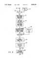
- FIG. 2is a detailed, semidiagrammatic representation of the present invention
- FIG. 3is an alternative diagrammatic representation of a gas analysis system in accordance with the present invention, in use with a pediatric ventilator;
- FIG. 4is a graph of the pressure curve of a time cycled pressure ventilator showing inspiratory flow
- FIG. 5is a graph of FLOW RATE, the corresponding SAMPLE CONTROL SIGNAL, and increase in VARIABLE VOLUME;
- FIG. 6is graph of the transfer of the sample gas during the transfer interval from the VARIABLE VOLUME RESERVOIR to the SAMPLE CELL, and the corresponding control signals;
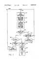
- FIGS. 7-9are a flow chart of a program for the monitor mode.
- FIG. 1shows a patient 10 (here, an infant) breathing with the assistance of a pediatric ventilator 12.
- the ventilator 12is of the constant-flow, time-cycled type that is commonly used to ventilate infants, and is well-known in the art.
- An exampleis the BEAR CUB® Ventilator, manufactured by Bear Medical Systems, Inc., of Riverside, Calif.
- the ventilator 12is connected to the patient 10 by a patient circuit comprising an inspiratory line 14, an expiratory line 16, and a patient connection tube 18, all connected by a patient connector 20, of a type well-known in the art.
- a stream of gas(typically air or oxygen-enriched air) is delivered from the ventilator 12 to the connector 20 via the inspiratory line 14.
- gastypically air or oxygen-enriched air
- the patentdraws from this gas stream through the patient connection tube 18 during inhalation, and returns exhaled gases to the connector 20 through the tube 18 during exhalation.
- the gas streamperiodically supplemented by the exhalation flow, is returned from the connector 20 back to the ventilator 12 by the expiratory line 16.
- the expiratory line 16terminates in an exhalation valve 22 that is automatically operated by the ventilator to close during inhalation and open during exhalation.
- the ventilatoralso includes a proximal pressure line 24 that leads from the patient connector 20 to a pressure transducer (not shown) in the ventilator.
- the pressure transducermeasures the proximal pressure of the connector 20 to determine if the proximal pressure limit set on the ventilator by the clinician has been reached or exceeded.
- the measured proximal pressureis advantageously displayed on a gauge 26 or a digital display (not shown).
- the patient connector 20has a patient port 28, in which is installed a high-sensitivity flow sensor 30.
- the flow sensor 30is preferably of the hot-wire type, with a capability of distinguishing between expiratory and inspiratory flows. Such a flow sensor is disclosed in U.S. Pat. No. 4,363,238, the disclosure of which is incorporated herein by reference.
- the flow sensor 30generates a flow rate-indicative output signal that is fed, along a line 32, into a volume monitor 34, as will be described below.
- the proximal side (from the patient) of the flow sensor 30is connected to the patient connection tube 18 by means of a tube adaptor 36.
- the patient connector 20is provided with a gas sampling port 38 in the patient port 28, and on the distal side (from the patient) of the flow sensor 30.
- the gas sampling port 38has an inlet 39 inside the patient port 28 and an outlet outside the patient port.
- the sampling port inlet 39is advantageously directed toward the proximal (patient) end of the connector 20.
- the gas sampling port outletis connected, by a sampling tube 40, with the sampling inlet of a gas analyzer 42.
- the gas analyzer 42is an oxygen/carbon dioxide analyzer and will be described in detail below.
- the sampling tube 40is advantageously provided with a water filter 44, of a type well-known in the art.
- the volume monitor 34is of a type, well-known in the art, that is capable of receiving and processing the output signal of the flow sensor 30 to produce a measurement of the patient's tidal volume
- a suitable volume monitoris the BEAR® NVM-1 Neonatal Volume Monitor, marketed by Bear Medical Systems, Inc. of Riverside, Calif. This particular volume monitor is specifically designed for use with a flow sensor of the type described in U.S. Pat. No. 4,363,238, discussed above.
- the volume monitor 34contains microprocessor circuitry that receives the flow rate signal from the flow sensor 30 and processes it to calculate the values of various respiratory parameters, and to provide a visual display of these values.
- the volume monitor 34can indicate the total exhaled tidal volume by simply integrating the exhaled flow rate signal over the total time of expiration. In addition, the volume monitor 34 processes the flow rate signal to provide an indication of the patient's breath rate.
- the volume monitor 34generates analog output signals indicative of flow rate, minute volume, and breath rate. These output signals are fed into the control circuitry 50 of the invention. As shown in FIG. 2, the control circuitry 50 includes an analog-to-digital converter 52 that receives the analog output signals from the volume monitor 34 and digitizes them for input into a microprocessor 54. For reasons that will later be apparent, the microprocessor's output signals are amplified by an amplifier 56 that is included in the control circuitry 50.
- the gas analyzer 42employs conventional gas analysis principles in operation (as will be described below), but it is modified for use in the present invention.
- the analyzer 42includes a pump comprising a piston 58 that is driven by a motor 59 and drive screw 60, for reciprocation within a cylinder 61.
- the cylinder 61which functions as a variable-volume reservoir, has an inlet/outlet port 62 that is coupled, by a "tee" fitting 64, to the downstream ends of the sampling tube 40 and a calibration tube 66, and to the upstream end of an outlet tube 68.
- the upstream end of the calibration tube 66is fluidly coupled to the patient connector 20 near the juncture with the inspiratory line 14. Gas flow from the calibration tube 66 is controlled by a solenoid actuated calibration flow valve 70
- Gas flow from the sample tube 40 into the "tee" fitting 64is controlled by a main flow control valve 72 that is solenoid actuated.
- the downstream end of the outlet tube 68feeds into an inlet 74 of a fixed-volume reservoir or sample cell 76, with gas flow into the sample cell 76 being controlled by a solenoid-actuated sample cell inlet valve 78.
- the sample cell 76has an outlet 80 that leads to an atmospheric venting port 82 through a solenoid-actuated outlet valve 84.
- the sample cell 76is optically coupled to an oxygen/carbon dioxide sensor unit 86, the latter being optically coupled also a plurality of reference cells, collectively designated by the numeral 88.
- the sensor unit 86is, essentially, an electro-optical device that includes nondispersive infrared (NDIR) analyzers for measuring carbon dioxide concentrations, and polarographic or galvanic sensors for measuring oxygen concentrations.
- NDIRnondispersive infrared
- the sensor unit 86also includes the electronic circuitry for comparing the sensor signals received from the reference cells 88 with those received from the sample cell 76 to generate an electrical output signal indicative of the concentration of the selected gas in the sample cell 76, and for generating an appropriate visual display in response to the electrical output signal.
- the cylinder 61is provided with an "empty" position sensor 92 and “full” position sensor 94.
- the empty position sensor 92is located so as to sense the piston 58 when piston is at the "top” of its stroke, and the full position sensor is locate so as to sense the "bottom” of the piston's stroke.
- the position sensors 92 and 94can be of any well-known type, such as optical or magnetic. Alternatively, the sensors 92 and 94 can be momentary contact switches that are momentarily closed by contact with the piston 58.
- the volume of the cylinder 61is selected in accordance with the volume required by the sensor unit 86 to make accurate measurements of oxygen and carbon dioxide concentration.
- the volume of the sample cell 76is similarly selected.
- An interactive display unit 96is operatively connected to the microprocessor 54, so as to allow an operator to view a visual display of the measurements being made and to provide certain inputs to the control circuitry, as will be described below.
- An advantageous optionis an oxygen analyzer 98 that receives gas from the inspiratory line 14 through a conduit 100, and produces an analog output signal indicative of the oxygen concentration in the inspiratory gas. This output signal is fed via an output line 102 into the A/D converter 52 for inputting into the microprocessor.
- the oxygen analyzer 98may be any suitable, commercially available device. The purpose of the oxygen analyzer 98 will be discussed below.
- the ventilatoris operated to deliver a continuous flow at a nominal oxygen concentration of 21%, the concentration in normal atmospheric air. This concentration can be verified with the oxygen analyzer 98.
- the microprocessortransmits a signal over a first valve activation line 104 to the calibration flow valve 70 (the signal having first been suitably amplified by the amplifier 56 to a voltage level sufficient to actuate the solenoid of the valve).
- the calibration flow valve 70then opens. Simultaneously, the microprocessor transmits a signal to the motor 59, via a motor actuation line 106, to start the piston 58 moving away from the cylinder port 62, that is, to start the piston's "downward" or intake stroke. Gas from the inspiratory line 14 is thus drawn through the calibration tube 66 and the calibration flow valve 70 into the cylinder 61. All of the other solenoid valves are closed while this gas sample is being drawn into the cylinder.
- the sensor 94When the full position sensor 94 senses the fully withdrawn position of the piston 58, the sensor 94 triggers a signal to the microprocessor 54, via a position signal line 108. This position sensor signal causes the microprocessor to transmit a signal to the calibration flow valve 70 to close that valve. The microprocessor also transmits a signal (amplified by the amplifier 56) via second valve activation line 110, to the sample cell inlet valve 78.
- the motor 60is signaled to reverse its motion to move the piston 58 toward the port 62 on its "upward" stroke.
- the sampled gas that had been collected in the cylinder 61is thus pumped out of the cylinder, through the outlet tube 68, and into the sample cell 76 through its inlet 74.
- a reading of the actual oxygen concentrationis then taken by means of the sensor unit 86, with reference to the appropriate one of the reference cells 88. This reading establishes a base value for the 21% oxygen calibration. Again, this value can be verified by the optional oxygen analyzer 98.
- the microprocessorsignals the sample cell inlet valve 78 to close, while transmitting a signal (amplified by the amplifier 56) along a third valve actuation line 112, that opens the outlet valve 84 to exhaust the contents of the sample cell through the venting port 82. This test is preferably performed two or three times to establish the best base value.
- the above described procedureis then repeated with the oxygen blender (not shown) of the ventilator set to deliver pure oxygen.
- the sample cell 76is filled with gas that is, nominally, 100% oxygen, and 0% carbon dioxide.
- a reading of the actual oxygen and carbon dioxide concentrationsis then taken by means of the sensor unit 86, with reference to appropriate ones of the reference cells 88.
- a final calibration testis performed by using the sensor unit to take a "reading" of a reference cell containing 40% carbon dioxide mixed with 60% inert gas. Once the calibration has been completed, the patient is connected to the system, and the operator selects the operational mode. The microprocessor first calculates a value for the volume of the sampling tube 40, either from inputted values of length and diameter, or from stored values.
- a breath flow rate signalis generated by the flow sensor 30 and fed into the volume monitor 34.
- the volume monitorcalculates, from the signal received from the flow sensor, values for total exhaled tidal volume and breath rate. These values are represented by a signal transmitted from the volume monitor 34 to the microprocessor 54, after having been digitized by the A/D converter 52.
- the microprocessor 54receives the expiratory tidal volume and breath rate signals from the volume monitor and from these signals, calculates the time required to collect the volume of exhaled gas necessary for the performance of the oxygen/carbon dioxide concentration analysis. With this inputted data, the microprocessor also calculates the number of breaths that will have to be collected in the piston 61 before the analysis can be performed.
- the microprocessoralso calculates the time it will take to flush the sampling tube 40, using the previously-calculated and stored value for the volume of the sampling tube. The microprocessor thus "knows” when an exhalation is commenced, the expected duration of the exhalation, and the expected total tidal volume of the exhalation. From the values of these parameters, plus the value of the "flush interval" for flushing the sampling tube, the microprocessor determines the commencement of the end tidal region of each exhaled breath, at which point in time the sampling process is begun.
- the microprocessoris programmed to begin the sampling process after a delay that is equal to the "flush interval"plus approximately ten per cent of the calculated exhalation period. This sampling delay assures that the sampled exhalation breath is taken from the end tidal region of the exhalation period.
- the microprocessortransmits a signal via a fourth valve actuation line 114 that (after amplification by the amplifier 56) opens the main flow control valve 72. All of the other solenoid valves are closed. A signal is then sent to the pump motor 59, whereby the motor is actuated to move the piston 58 away from the cylinder port 62, thereby drawing gas from the sampling tube 40 through the main valve 72, into the cylinder 61.
- the main valve 72is signaled to close, and it remains closed until the onset of the next exhalation period, plus the next sampling delay that is measured from the beginning of exhalation. After the next sampling delay, the main valve 72 is opened and the piston 58 is once again actuated to continue its intake stroke (which is interrupted by an appropriate signal to the motor 59 when the main valve 72 is closed).
- the piston 58triggers the "empty" position sensor 92, thereby transmitting a signal over the position signal line 108 that causes the microprocessor to stop the motor 59 and to close the sample cell inlet valve 78.
- the main valve 72can again be opened to admit the first of another series of samples to be collected in the cylinder 61, as previously described.
- An internal clock (not shown) in the microprocessorindicates that sufficient time has elapsed for the gas concentration analyses to have been performed.
- the microprocessorthen transmits a signal that opens the sample cell outlet valve 84, allowing the gas in the sample cell 76 to be vented to atmosphere via the outlet 80 and the venting port 82.
- the internal clock of the microprocessormay be advantageous to have the internal clock of the microprocessor measure the elapsed time between the opening of the main valve 72 and the triggering of the "full" sensor 94, and to have this measured sampling time displayed.
- the measured sampling time and the calculated sampling timecan be compared by the microprocessor, and if the deviation between them exceeds a pre-set limit, the microprocessor can be programmed to adjust the timing of the valve and motor actuation signals, as appropriate.
- the oxygen analyzer 98may be useful to employ the oxygen analyzer 98 to obtain a measurement of the oxygen concentration, in the inspiratory line 14 of the ventilator patient circuit.
- the digitized signal from the oxygen analyzer 98is inputted to the microprocessor 54, where it is compared to the oxygen concentration measured in the sample cell 76 to obtain calculated values for oxygen consumption and carbon dioxide production by the patient, thereby providing an indication of the patient's metabolic work.
- FIG. 3is an alternative block diagram for the exhaled gas concentration analysis system of FIGS. 1 and 2.
- the phantom block 12represents a conventional, time-cycled, pressure-limited ventilator for periodically delivering an inspiratory gas stream to a patient and an expiratory gas stream from a patient.
- the pressure curve of FIG. 4represents the pressure applied to the infant via the patient connector 20 and the associated tubing. The pressure is shown rising to a peak pressure and then dropping to a slightly positive level referred to as the positive end expiratory pressure (PEEP) level.
- PEEPpositive end expiratory pressure
- the phantom block 120represents a volume monitoring system for measuring the flow rate of the inspiratory and expiratory gas streams.
- the volume monitoring systemprovides a tidal volume signal via a first signal line 122, a breath rate signal via a second signal line 124, and a flow rate signal via a third signal line 126, to the control circuitry 50. In an alternative embodiment (not shown), these signals would be provided on a digital signal bus as digital data values.
- the volume monitor system 120includes the flow sensor 30 and the volume monitor 34.
- the control circuitry 50is responsive to the tidal volume signal, the breath rate signal, and the flow rate signal for generating a sample control signal along an output line 128.
- the sample control signalprecisely marks an interval occurring between a time T3 and a time T4 within the end tidal period of each successive expiratory gas stream from the patient 10.
- the phantom block 42 in FIG. 3represents a gas analyzer system that is responsive to the sample control signal for extracting a sample of the expiratory gas stream within the end tidal period interval and accumulating each of the samples of the expiratory gas stream selected in a variable volume reservoir (the cylinder 61).
- the gas analyzer system 42is shown having a sample cell 76 that receives the gas accumulated within the variable volume reservoir or cylinder 61 in response to the gas volume in the cylinder reaching a predetermined limit established by the activation of the full position sensor 94.
- the ventilator system 12 of FIG. 3is shown having an inspiratory line 14 and an expiratory line 16, each having an upstream end and a downstream end.
- the ventilator 12provides the inspiratory gas stream via the line 14 to an inspiratory line upstream end 132, and receives the expiratory gas stream from an expiratory line downstream end 134.
- the patient connector 20couples the inspiratory gas stream from the inspiratory line to the patient and couples the expiratory gas stream from the patient to the expiratory line.
- the volume monitor system 120 of FIG. 3has the flow sensor 30 coupled to the patient connector 20 to sense the inspiratory and expiratory gas streams, to provide a flow rate signal indicating the flow rates of the patient's inspiration and expiration.
- the volume monitor 34is responsive to the flow rate signal for calculating the tidal volumes of the inspiratory and expiratory gas flows from the inspiratory and expiratory flow rate signals, by integrating the amplitudes of the inspiratory and expiratory flow rate signals with respect to time over the total times of inspiration and expiration, respectively.
- the volume monitor system 120is further characterized to provide a breath rate signal by measuring the period between expiratory intervals and dividing the measured period into a predetermined time interval.
- the control circuitry 50is coupled to the interactive display 96 for inputting data and for displaying the values of the breath rate signal on the second signal line 124, and the flow rate signal on the third signal line 126.
- the control circuit 50also includes the analog-to-digital converter 52 shown in FIG. 2, for converting values of the flow rate signal, the tidal volume signal and the breath rate signal into digital values, and for inputting these digital values into the microprocessor 54 (FIG. 2) within control circuit 50.
- the microprocessor 54can thus use the rawest signal data from the volume monitor 34 without being dependent on the volume monitor's computational processing.
- the sample control signalis terminated at T4 in advance of a time T5 which designates the cross-over from exhalation to inhalation to assure that only exhaled gas is sampled.
- the piston drive motor 59(FIG. 2) drives the piston 58 through a sequence of incremental intake translations in response to a corresponding sequence of sample control signals to accumulate a sequence of expiratory gas samples through the cylinder port 62 from successive end tidal periods of exhalation.
- the drive motoralso drives the piston through a total exhaust translation to empty the cylinder through the cylinder port in response to the variable volume reservoir reaching a predetermined volume limit, such as that defined by the actuation of the full sensor 94.
- the pressure curveschematically represents the pressure applied to an infant by a time cycled, pressure limited system.
- Most of the pediatric ventilators currently in useare of this type.
- the volume demanded by the infanthas little influence on the applied pressure, since pressure is regulated, not flow rate.
- the infantadjusts its breathing rate to match the pressure curve of the ventilator.
- the design of the ventilatorprovides for a pre-identified pressure cap.
- the pressureis limited and can not exceed the maximum pressure shown.
- the ventilatorreleases the applied pressure and returns the pressure to a slightly positive pressure level referred to as the positive end expiratory pressure or PEEP.
- PEEPpositive end expiratory pressure
- FIG. 5shows the output of flow sensor 30 by means of a flow rate waveform 5(a).
- flow ratehas a positive value for flow moving toward the patient (inspiratory flow).
- the inspiratory flow ratereaches a peak magnitude at time T2 and then drops through zero to become a negative flow rate during the exhalation interval.
- the time between T2 and T3is a delay interval that is either preset as an absolute value in seconds or that is established by the program as a value that is functionally related to the breathing cycle rate or interval.
- the T2-T3 delaypermits the infant to move exhaled gas from the lungs through the patient connection tube 18 and to purge the flow sensor 30 before the main flow control valve 72 is opened.
- the reduction in pressureallows the infant to exhale.
- the lungsbegin to expand during inhalation.
- the pressureis released, the lungs relax and expel the gas in the same way that an inflated balloon collapses.
- the T2 to T5 intervalmarks the duration of the exhaled tidal volume.
- the exhaled tidal volumeis computed by the microprocessor as the integral of flow rate.
- a waveform 5(b)represents the sample control signal.
- the sample control signalassumes a positive value which is then amplified and used to open the main flow control valve 72 and to run the piston drive motor to expand the volume of variable volume reservoir 61.
- microprocessor 54permits the system to accommodate and adjust for changes in the system delays, such as the delay from T2-T3 and the delay from T4 -T5, that may result from component variations or types, and which may vary from one system to the next, or which may not be known at the time the system is built.
- the delayscan be adjusted by software or program changes.
- FIG. 6shows the relationship between several waveforms as the variable volume reservoir actuates the full sensor 94.
- the wave form 6(a)shows the last sample control signal occurring as the variable volume represented by the waveform 6(b) exceeds a predetermined limit at a time T6.
- the waveform 6(b)representing the variable volume of the variable volume reservoir 61, is seen to be increasing as exhaled gas is drawn into the cylinder.
- the waveform 6(d)represents the momentary actuation of the full sensor 94 (represented as the closure of switch), signaling that the predetermined volume limit of the cylinder is reached.
- the sample control signalis terminated with the actuation of the full sensor 94, and the flow control valve 72, represented by the waveform 6(e), is closed at the same instant.
- the gas transfer sequence from the variable volume reservoir 61 to the sample cell 76begins at T7 as the waveform 6(g) goes high to signal the opening of sample cell inlet valve 78.
- Waveforms 6(b) and 6(c)show the variable volume decreasing as the motor drives the piston forward to empty the cylinder 61.
- the sample cell volume of gasis increasing during the same interval.
- the transferis complete with the activation of the empty sensor 92, represented as the closure of a switch by the waveform 6(f).
- the sample cell inlet valve 78closes, sealing the gas in the sample cell 76 for analysis.
- the time T9marks the completion of the analysis.
- the waveform 6(h)shows the opening of the sample cell outlet valve 84 at time T9, after the completion of the analysis, and its closing at time T10. While open, the sample cell outlet valve 84 allows the purging of gas from sample cell 66.
- FIGS. 7-9represent a flow chart for a microprocessor program for the blood gas analysis system described above. As the system is activated, the microprocessor refers to an entry address circle 140 for its first instruction. A block 142 represents a clear and initialization process on entering the program sequence for the first time at turn on. Fixed constants and program instructions are typically available from a read only memory that may be electronically programmable.
- a block 144represents the step of reading the outputs of the A/D converter 52 and storing the current values of tidal volume, breath rate and flow rate.
- a block 146represents the step of updating the stored values of tidal volume, breath rate and tidal period.
- a monitor mode decision block 148determines if the system is in the monitor mode.
- a selector switch(not shown) on the interactive display 96 (FIG. 2) can be used to provide a signal to the microprocessor to indicate that the system is in the monitor mode. If the system is not in the monitor mode, the system advances to a calibration block 150 to determine if the system is in the calibration mode. If the system is in the calibration mode, the system performs a calibration subroutine (not shown), and returns to the program entry point at the entry address circle, 140 via a return command block 152.
- the programadvances from the decision block 148 to a flow rate decision block 156 to determine if the flow rate is positive or negative. If the flow rate is positive, the patient is inhaling and the program returns to the program entry 140 via blocks 158 and 160, setting an "inhale" flag in the process.
- the programdetermines that the flow rate is negative, then the patient is exhaling, and the program advances to a block 162 to set the "exhale" flag.
- the inhale and exhale flagscan be used to signal drivers to light appropriate indicators (not shown) on the interactive panel 96.
- the systemthen advances to a block 164 to calculate the T3 and T4 times or the time delays from cross over for T3 and T4. If the values are pre-stored, then the system will advance from this block immediately. However, if the system is required to develop historical data with which to calculate T3 and T4, then the system will remain in the block 164 routine for the interval required, after which the program advances to a first intermediate location circle, 166 for its next instruction.
- FIG. 8shows the program advancing to a decision block 168 to determine if the time elapsed is within the range of between T3 and T4. If not, the program returns via a block 170 to the entry circle, 140. If the decision routine determines that time T is in that range, the program advances through the block 170 to a block 172, to update the received data from the A/D converter 52, and then to a block 174 to update the stored values and the historical averages.
- the programadvances to a block 176 to set the sample control signal flag.
- Drivers(not shown) coupled to this signal also control the run motor signal for actuating the motor 59 that drives the piston 58 in the cylinder 61.
- the programadvances to a full sensor decision block 178 to determine if the full sensor or switch 94 is actuated or closed. If switch 94 is not closed, the system returns via a block 180 to the first intermediate location address circle 166.
- variable volume reservoiris full.
- the programadvances to a block 182 to reset the sample control flag.
- the programthen advances to a block 184 to close the valves 70, 72, 84 and to open the sample cell inlet valve 78 to allow gas to be transferred to the sample cell 76.
- the programnext advances past a second intermediate location circle 186 to a block 188 to turn on the motor 59 to drive the piston 58 forward to transfer gas to the sample cell from the cylinder.
- the programthen advances to third intermediate location circle 200 at the top of FIG. 9.
- the programadvances to an empty sensor decision block 202 to determine if the empty sensor or switch 92 is actuated or closed. Closure of the switch 92 signals that the gas has been transferred from the cylinder 61 to the sample cell 76. If the decision is "no" (the switch 92 being open), the program loops to the second intermediate location circle 186 via a block 204.
- the programadvances to the stop motor block 206 and resets a flag or commands a predetermined logic level on a discrete signal line to provide a logic level to a control circuit, such as a solid state relay (not shown) to interrupt power to the motor.
- the programthen advances to a block 208 to set a second flag or to command a predetermined logic level on a second discrete signal line.
- the predetermined logic signal on the second signal linesignals the analyzer to start the analysis.
- the analyzer 86provides a discrete logic signal to the microprocessor at the completion of the analysis, or, in an alternative embodiment, a predetermined time is allowed for the analysis, after which the program advances past an analysis completion decision block 210 to a block 212 to output a discrete control signal to open the sample cell outlet valve 84. The program then advances to a calculation block 214.
- each sample intervalrequires monitoring data taken during a number of patient breath intervals.
- Each sample intervalbegins with an initialization of all register values required to assure that all flags or discrete outputs and inputs are initialized to their proper values and the breath count register (not shown) is initialized to zero (0).
- the microprocessor programdirects the microprocessor to increment the breath count register.
- the microprocessorstops incrementing the breath count register and transfers the value of the NUMBER OF BREATHS PER SAMPLE CYCLE for the signal interval to a latch register for display.
- the microprocessorcalculates the values of Tev, the time period required to collect the volume of gas in the variable volume reservoir or cylinder 61.
- the programincrements a breath count register by one count each time the program passes through the "N" or "no" exit of the full sensor decision block 178 in FIG. 8.
- the programalso records the start time from a real time clock as it sets the exhale flag in the block 162 of FIG. 7 at the start of a sequence of breaths.
- the programalso reads and records the time of completion of a breath count sequence in real time as it leaves the decision block 178 of FIG. 8 on the "Y" or "yes" path.
- TevTIME PERIOD TO COLLECT A SAMPLE VOLUME (i.e. the time required to fill the cylinder 61).
- the value of Tevwill vary as a function of the breath rate and tidal volume of the patient.
- the program analysis processalso provides a measure of the average concentration of oxygen and carbon dioxide in the exhaled gas.
- concentrations of oxygen and carbon dioxide in the gasare known from each analysis.
- the values of these concentrationsare stored as data in registers for the last analysis and for a predetermined number of preceding analysis results.
- the programdisplays the present values of oxygen and carbon dioxide from the most recent analysis and also calculates the average values for display from the past historical data values.
- the programcalculates the total volume of exhaled gas from the patient for each breath by the integration of flow rate over time.
- the programsums these volume values to obtain the total volume of gas that is exhaled to fill the variable volume reservoir.
- the calculated tidal volumeis available for comparison with the value provided by the volume monitor 34.
- the relationship between flow rate through the flow sensor and flow into the gas sampling port 39is established by empirical tests when the machine is factory calibrated and a look-up table is stored in a read only memory.
- the programuses this stored empirical data with the measured flow rate to obtain a predicted value of flow into the variable volume chamber.
- the programcalculates the total volume of exhaled gas that is passed to the variable volume reservoir as the reservoir is expanded to its known volume limit. The calculated flow to the reservoir, along with the total amount of gas that is leaving the patient during the exhalation periods, is available for display.
- the programoutputs and displays the TIME PERIOD PER CYCLE by dividing the total time required to fill the variable volume reservoir 61 by the NUMBER OF BREATHS PER SAMPLE CYCLE to obtain the time period per cycle.
- the programreturns to the entry address location 140 after completing all calculations and outputting the data for display by the interactive display 96.
- the present inventionallows the collection of precisely-timed exhalation samples, each of which is controlled substantially to coincide with the end tidal period of an exhaled breath. Accurate analyses of exhaled oxygen and carbon dioxide concentration can be performed, even with the relatively rapid, shallow (i.e. low-volume) exhalations of an infant, while adult patients can also be accommodated, if desired. Furthermore, by the addition of the inspiratory line oxygen analyzer 98, the invention is uniquely adaptable to provide metabolic data not easily acquired by using prior art devices. These advantages are achieved using components that are largely off-the-shelf items thereby contributing to relatively low costs.
Landscapes
- Health & Medical Sciences (AREA)
- Life Sciences & Earth Sciences (AREA)
- Medical Informatics (AREA)
- Molecular Biology (AREA)
- Pulmonology (AREA)
- Biophysics (AREA)
- Pathology (AREA)
- Engineering & Computer Science (AREA)
- Biomedical Technology (AREA)
- Heart & Thoracic Surgery (AREA)
- Physiology (AREA)
- Physics & Mathematics (AREA)
- Surgery (AREA)
- Animal Behavior & Ethology (AREA)
- General Health & Medical Sciences (AREA)
- Public Health (AREA)
- Veterinary Medicine (AREA)
- Emergency Medicine (AREA)
- Obesity (AREA)
- Measurement Of The Respiration, Hearing Ability, Form, And Blood Characteristics Of Living Organisms (AREA)
- Investigating Or Analysing Biological Materials (AREA)
Abstract
Description
Claims (4)
Priority Applications (2)
| Application Number | Priority Date | Filing Date | Title |
|---|---|---|---|
| US07/357,469US5069220A (en) | 1989-05-26 | 1989-05-26 | Measurement of gas concentration in exhaled breath |
| PCT/US1990/002951WO1990014043A1 (en) | 1989-05-26 | 1990-05-23 | Measurement of gas concentration in exhaled breath |
Applications Claiming Priority (1)
| Application Number | Priority Date | Filing Date | Title |
|---|---|---|---|
| US07/357,469US5069220A (en) | 1989-05-26 | 1989-05-26 | Measurement of gas concentration in exhaled breath |
Publications (1)
| Publication Number | Publication Date |
|---|---|
| US5069220Atrue US5069220A (en) | 1991-12-03 |
Family
ID=23405738
Family Applications (1)
| Application Number | Title | Priority Date | Filing Date |
|---|---|---|---|
| US07/357,469Expired - Fee RelatedUS5069220A (en) | 1989-05-26 | 1989-05-26 | Measurement of gas concentration in exhaled breath |
Country Status (2)
| Country | Link |
|---|---|
| US (1) | US5069220A (en) |
| WO (1) | WO1990014043A1 (en) |
Cited By (83)
| Publication number | Priority date | Publication date | Assignee | Title |
|---|---|---|---|---|
| US5355893A (en)* | 1992-04-06 | 1994-10-18 | Mick Peter R | Vital signs monitor |
| US5363857A (en)* | 1990-05-22 | 1994-11-15 | Aerosport, Inc. | Metabolic analyzer |
| US5383469A (en)* | 1992-01-31 | 1995-01-24 | Board Of Trustees Of The Leland Stanford Junior University | Neonatal hemolysis detection using end-tidal breath sampler and analyzer apparatus |
| US5531096A (en)* | 1993-12-03 | 1996-07-02 | Siemens Elema Ab | Gas analyzer and method for analyzing a gas |
| US5533512A (en)* | 1994-03-18 | 1996-07-09 | Ohmeda Inc. | Method and apparatus for detection of venous air emboli |
| US5540220A (en)* | 1994-12-08 | 1996-07-30 | Bear Medical Systems, Inc. | Pressure-limited, time-cycled pulmonary ventilation with volume-cycle override |
| US5692497A (en)* | 1996-05-16 | 1997-12-02 | Children's Medical Center Corporation | Microprocessor-controlled ventilator system and methods |
| US5957128A (en)* | 1996-02-21 | 1999-09-28 | Hecker; Karl-Heinz | Method and device for determination of the functional residual capacity (FRC) |
| DE19833991A1 (en)* | 1998-07-29 | 2000-02-10 | Draeger Sicherheitstech Gmbh | Arrangement for detecting gaseous component in gas flow, e.g. alcohol in breath; has choke in sample extraction line, pressure sensor on upstream side of choke, flow detector for generating null flow signal |
| US6042550A (en)* | 1998-09-09 | 2000-03-28 | Ntc Technology, Inc. | Methods of non-invasively estimating intrapulmonary shunt fraction and measuring cardiac output |
| US6059732A (en)* | 1998-09-09 | 2000-05-09 | Ntc Technology, Inc. | ISO-volumetric method of measuring carbon dioxide elimination |
| US6200271B1 (en) | 1998-09-09 | 2001-03-13 | Ntc Technology Inc. | Bi-directional partial re-breathing method |
| US6210342B1 (en) | 1999-09-08 | 2001-04-03 | Ntc Technology, Inc. | Bi-directional partial re-breathing method |
| US6217524B1 (en) | 1998-09-09 | 2001-04-17 | Ntc Technology Inc. | Method of continuously, non-invasively monitoring pulmonary capillary blood flow and cardiac output |
| US6238351B1 (en) | 1998-09-09 | 2001-05-29 | Ntc Technology Inc. | Method for compensating for non-metabolic changes in respiratory or blood gas profile parameters |
| US6277645B1 (en) | 1998-08-03 | 2001-08-21 | James R. Mault | Method and apparatus for respiratory gas analysis employing measurement of expired gas mass |
| US6290713B1 (en) | 1999-08-24 | 2001-09-18 | Thomas A. Russell | Flexible illuminators for phototherapy |
| US6309360B1 (en) | 1997-03-17 | 2001-10-30 | James R. Mault | Respiratory calorimeter |
| US6360745B1 (en)* | 1997-03-14 | 2002-03-26 | Nellcor Puritan Bennett Incorporated | System and method for controlling the start up of a patient ventilator |
| US6402698B1 (en) | 1998-02-05 | 2002-06-11 | James R. Mault | Metabolic calorimeter employing respiratory gas analysis |
| US6406435B1 (en) | 1998-11-17 | 2002-06-18 | James R. Mault | Method and apparatus for the non-invasive determination of cardiac output |
| DE10106046A1 (en)* | 2001-02-09 | 2002-08-29 | Draeger Medical Ag | Combined breath flow sensor |
| US6468222B1 (en) | 1999-08-02 | 2002-10-22 | Healthetech, Inc. | Metabolic calorimeter employing respiratory gas analysis |
| US6478736B1 (en) | 1999-10-08 | 2002-11-12 | Healthetech, Inc. | Integrated calorie management system |
| US6482158B2 (en) | 2000-05-19 | 2002-11-19 | Healthetech, Inc. | System and method of ultrasonic mammography |
| US20030023181A1 (en)* | 2001-07-26 | 2003-01-30 | Mault James R. | Gas analyzer of the fluorescent-film type particularly useful for respiratory analysis |
| US6517496B1 (en) | 1999-05-10 | 2003-02-11 | Healthetech, Inc. | Airway-based cardiac output monitor and methods for using same |
| US6540689B1 (en) | 2000-02-22 | 2003-04-01 | Ntc Technology, Inc. | Methods for accurately, substantially noninvasively determining pulmonary capillary blood flow, cardiac output, and mixed venous carbon dioxide content |
| US20030065274A1 (en)* | 1999-08-02 | 2003-04-03 | Mault James R. | Method of respiratory gas analysis using a metabolic calorimeter |
| US20030106554A1 (en)* | 2001-11-30 | 2003-06-12 | De Silva Adrian D. | Gas identification system and volumetric ally correct gas delivery system |
| USD478660S1 (en) | 2002-07-01 | 2003-08-19 | Healthetech, Inc. | Disposable mask with sanitation insert for a respiratory analyzer |
| US6607387B2 (en) | 2000-10-30 | 2003-08-19 | Healthetech, Inc. | Sensor system for diagnosing dental conditions |
| US6612306B1 (en) | 1999-10-13 | 2003-09-02 | Healthetech, Inc. | Respiratory nitric oxide meter |
| US6620106B2 (en) | 2000-09-29 | 2003-09-16 | Healthetech, Inc. | Indirect calorimetry system |
| US6629934B2 (en)* | 2000-02-02 | 2003-10-07 | Healthetech, Inc. | Indirect calorimeter for medical applications |
| US20030208133A1 (en)* | 2000-06-07 | 2003-11-06 | Mault James R | Breath ketone analyzer |
| US6699202B1 (en)* | 2000-11-03 | 2004-03-02 | It Gambert Gmbh | Method and device for physiologic analysis |
| US20040082871A1 (en)* | 2001-02-16 | 2004-04-29 | Bradley Austen Peter | Respiratory oxygen consumption measuring device and method |
| US6790178B1 (en) | 1999-09-24 | 2004-09-14 | Healthetech, Inc. | Physiological monitor and associated computation, display and communication unit |
| US20040243016A1 (en)* | 2001-08-29 | 2004-12-02 | Sanderson Penelope Margaret | Method and means of physiological monitoring using sonification |
| US20050115834A1 (en)* | 2003-12-01 | 2005-06-02 | Erich Wolf | Self-condensing pH sensor |
| EP1547523A1 (en)* | 2003-12-24 | 2005-06-29 | Instrumentarium Corporation | Method and apparatus for synchronizing respiratory gas measurements |
| US20050177056A1 (en)* | 2002-03-03 | 2005-08-11 | Oridion Breathid Ltd | Breath collection system |
| WO2006068622A1 (en)* | 2004-12-20 | 2006-06-29 | Nanyang Polytechnic | System and method for detecting of pulmonary diseases |
| US7101341B2 (en) | 2003-04-15 | 2006-09-05 | Ross Tsukashima | Respiratory monitoring, diagnostic and therapeutic system |
| US7135001B2 (en) | 2001-03-20 | 2006-11-14 | Ric Investments, Llc | Rebreathing methods including oscillating, substantially equal rebreathing and nonrebreathing periods |
| US20070021681A1 (en)* | 2005-07-14 | 2007-01-25 | Michael Sokoloff | Method and system for non-invasively measuring pulmonary function |
| US20070167683A1 (en)* | 2006-01-19 | 2007-07-19 | Boston Scientific Scimed, Inc. | Endoscopic system with integrated patient respiratory status indicator |
| US7291114B2 (en) | 2002-04-01 | 2007-11-06 | Microlife Corporation | System and method of determining an individualized drug administration protocol |
| US20070265877A1 (en)* | 2006-05-12 | 2007-11-15 | Rice Caeli B D | Informative accessories |
| US20070293780A1 (en)* | 2004-05-27 | 2007-12-20 | Aryeh Ben-Yosef | Capnography Apparatus |
| US20080027344A1 (en)* | 2006-07-27 | 2008-01-31 | Ric Investments, Llc | Modular sidestream gas sampling assembly |
| US7392193B2 (en) | 2000-06-16 | 2008-06-24 | Microlife Corporation | Speech recognition capability for a personal digital assistant |
| US7422723B1 (en) | 2003-10-24 | 2008-09-09 | Alcohol Detection Systems, Inc. | Alcohol breath test device |
| US20090281443A1 (en)* | 2008-05-08 | 2009-11-12 | Drager Medical Ag & Co. Kg | Device for taking and analyzing breathing gas samples |
| US7699788B2 (en) | 2000-02-22 | 2010-04-20 | Ric Investments, Llc. | Noninvasive effective lung volume estimation |
| US20120031165A1 (en)* | 2010-08-09 | 2012-02-09 | Ruocco John T | Breath sampling methodology having improved reliability |
| GB2497304A (en)* | 2011-12-06 | 2013-06-12 | Tecom Analytical Systems | Estimation of energy expenditure |
| US8485183B2 (en) | 2008-06-06 | 2013-07-16 | Covidien Lp | Systems and methods for triggering and cycling a ventilator based on reconstructed patient effort signal |
| US8714154B2 (en) | 2011-03-30 | 2014-05-06 | Covidien Lp | Systems and methods for automatic adjustment of ventilator settings |
| US20140364758A1 (en)* | 2011-12-19 | 2014-12-11 | Resmed Limited | Respiratory treatment system including physiological sensors |
| WO2015031850A1 (en)* | 2013-08-30 | 2015-03-05 | Capnia, Inc. | Neonatal carbon dioxide measurement system |
| US20150065901A1 (en)* | 2013-08-30 | 2015-03-05 | Capnia, Inc. | Universal breath sampling and analysis device |
| US9541517B2 (en) | 2011-09-16 | 2017-01-10 | The Research Foundation For The State University Of New York | Low concentration ammonia nanosensor |
| WO2017049247A1 (en)* | 2015-09-16 | 2017-03-23 | 12th Man Technologies, Inc. | Non-gas analyzer monitor of inspired gas concentration |
| US9678058B2 (en) | 2010-09-03 | 2017-06-13 | Anastasia Rigas | Diagnostic method and breath testing device |
| US20170325716A1 (en)* | 2016-05-15 | 2017-11-16 | Covidien Lp | Side-stream volumetric capnography |
| US9885693B2 (en)* | 2013-04-16 | 2018-02-06 | Dräger Safety AG & Co. KGaA | Measuring device, reaction carrier and measuring method |
| CN107874761A (en)* | 2011-12-21 | 2018-04-06 | 卡普尼亚公司 | Collected in the case where compensating respiration parameter frequency and analyze the gas of the exhalation of certain volume |
| US9936897B2 (en) | 2003-06-19 | 2018-04-10 | Capnia, Inc. | Breath end-tidal gas monitor |
| US20190086376A1 (en)* | 2015-11-19 | 2019-03-21 | Analytik Jena Ag | Analysis device and method |
| US10401318B2 (en) | 2011-03-14 | 2019-09-03 | Anastasia Rigas | Breath analyzer and breath test methods |
| US10499819B2 (en) | 2013-01-08 | 2019-12-10 | Capnia, Inc. | Breath selection for analysis |
| US10568568B2 (en) | 2014-08-27 | 2020-02-25 | Capnia, Inc. | Methods for immune globulin administration |
| US10596903B2 (en) | 2015-10-13 | 2020-03-24 | Consumer Safety Technology, Llc | Networked intoxication vehicle immobilization |
| US10663440B2 (en) | 2016-09-09 | 2020-05-26 | Consumer Safety Technology, Llc | Secure data handling in a breath alcohol calibration station |
| US20200359935A1 (en)* | 2017-11-09 | 2020-11-19 | Children's Medical Center Corporation | Oxygen Consumption and Energy Expenditure Monitoring |
| US10877008B2 (en) | 2016-09-09 | 2020-12-29 | Consumer Safety Technology, Llc | Reference gas management in a breath alcohol calibration station |
| US11331004B2 (en) | 2013-02-12 | 2022-05-17 | Capnia, Inc. | Sampling and storage registry device for breath gas analysis |
| US20230022188A1 (en)* | 2019-12-02 | 2023-01-26 | Lung-Diagnostics Gmbh | Lung testing device |
| US12150752B2 (en) | 2018-12-10 | 2024-11-26 | Anastasia Rigas | Hydrogen breath analyzer and breath test method |
| US12311759B1 (en) | 2022-02-02 | 2025-05-27 | Consumer Safety Technology, Llc | Wireless vehicle interface for immobilization system |
| US12414710B2 (en) | 2018-12-10 | 2025-09-16 | Anastasia Rigas | Breath analyzer devices and breath test methods |
Families Citing this family (16)
| Publication number | Priority date | Publication date | Assignee | Title |
|---|---|---|---|---|
| JPH07116145A (en)* | 1993-10-25 | 1995-05-09 | Kyoto Daiichi Kagaku:Kk | Apparatus for collecting exhalation |
| JP3325673B2 (en)* | 1993-10-25 | 2002-09-17 | アークレイ株式会社 | Method for correcting component concentration in breath and breath analyzer |
| FI96579C (en)* | 1994-11-14 | 1996-07-25 | Instrumentarium Oy | Method to prevent the formation of dangerous vacuum in the respiratory system |
| EP0834073B1 (en) | 1995-06-19 | 2000-08-30 | Btg International Limited | Animal exhalation monitoring |
| EP0774233A1 (en)* | 1995-11-15 | 1997-05-21 | Instrumentarium Corporation | Method of preventing the formation of a dangerous underpressure in a respiratory system |
| US5676132A (en)* | 1995-12-05 | 1997-10-14 | Pulmonary Interface, Inc. | Pulmonary interface system |
| GB2497341B (en)* | 2011-12-08 | 2016-08-03 | Europlaz Tech Ltd | Respiratory gas flow sensor with sampling port |
| US9933445B1 (en) | 2016-05-16 | 2018-04-03 | Hound Labs, Inc. | System and method for target substance identification |
| US11026596B1 (en) | 2017-05-19 | 2021-06-08 | Hound Labs, Inc. | Detection and measurement of target substance in exhaled breath |
| US11187711B1 (en) | 2017-09-11 | 2021-11-30 | Hound Labs, Inc. | Analyte detection from breath samples |
| US11426097B1 (en) | 2018-10-17 | 2022-08-30 | Hound Labs, Inc. | Rotary valve assemblies and methods of use for breath sample cartridge systems |
| WO2020097382A1 (en)* | 2018-11-09 | 2020-05-14 | Hound Labs, Inc. | Breath sample systems for use with ventilators |
| US20200245898A1 (en) | 2019-01-31 | 2020-08-06 | Hound Labs, Inc. | Single-use Microfluidic Cartridge for Detection of Target Chemical Presence in Human Breath |
| US11977086B2 (en) | 2019-03-21 | 2024-05-07 | Hound Labs, Inc. | Biomarker detection from breath samples |
| US11933731B1 (en) | 2020-05-13 | 2024-03-19 | Hound Labs, Inc. | Systems and methods using Surface-Enhanced Raman Spectroscopy for detecting tetrahydrocannabinol |
| US12392769B1 (en) | 2021-01-12 | 2025-08-19 | Hound Labs, Inc. | Ambient contamination in breath analyte detection and measurement |
Citations (12)
| Publication number | Priority date | Publication date | Assignee | Title |
|---|---|---|---|---|
| US3395701A (en)* | 1965-10-29 | 1968-08-06 | Navy Usa | End tidal sampler for an oxygen breathing mask |
| US3818901A (en)* | 1972-04-12 | 1974-06-25 | Del Mar Eng Lab | Apparatus for automatically periodically measuring and displaying the total air expired by a subject during each of a succession of given time intervals |
| US3834375A (en)* | 1972-04-12 | 1974-09-10 | Del Mar Eng Lab | Respiratory gas analyzer for measuring and displaying oxygen uptake in expired air |
| US3910261A (en)* | 1974-06-11 | 1975-10-07 | Bourns Inc | End-tidal gas analysis apparatus for respirators |
| US4011859A (en)* | 1974-09-05 | 1977-03-15 | Dragerwerk Aktiengesellschaft | Method for continuously measuring the CO2 content in breathing gases |
| US4202352A (en)* | 1978-04-06 | 1980-05-13 | Research Development Corporation | Apparatus for measurement of expired gas concentration in infants |
| US4269196A (en)* | 1977-04-05 | 1981-05-26 | Toms Norman D | Pediatric tidal volume indicator and ventilator adaptation |
| US4297871A (en)* | 1978-11-03 | 1981-11-03 | Wright Basil M | Gas sampling devices |
| US4346584A (en)* | 1980-10-20 | 1982-08-31 | Boehringer John R | Gas analyzer |
| US4423739A (en)* | 1981-08-24 | 1984-01-03 | Andros Analyzers Incorporated | End tidal carbon dioxide gas analyzer |
| US4572208A (en)* | 1983-06-29 | 1986-02-25 | Utah Medical Products, Inc. | Metabolic gas monitoring apparatus and method |
| US4619269A (en)* | 1983-06-29 | 1986-10-28 | Utah Medical Products, Inc. | Apparatus and method for monitoring respiratory gas |
Family Cites Families (1)
| Publication number | Priority date | Publication date | Assignee | Title |
|---|---|---|---|---|
| US3850036A (en)* | 1972-04-12 | 1974-11-26 | Del Mar Eng Lab | Respiratory gas sampler |
- 1989
- 1989-05-26USUS07/357,469patent/US5069220A/ennot_activeExpired - Fee Related
- 1990
- 1990-05-23WOPCT/US1990/002951patent/WO1990014043A1/enunknown
Patent Citations (12)
| Publication number | Priority date | Publication date | Assignee | Title |
|---|---|---|---|---|
| US3395701A (en)* | 1965-10-29 | 1968-08-06 | Navy Usa | End tidal sampler for an oxygen breathing mask |
| US3818901A (en)* | 1972-04-12 | 1974-06-25 | Del Mar Eng Lab | Apparatus for automatically periodically measuring and displaying the total air expired by a subject during each of a succession of given time intervals |
| US3834375A (en)* | 1972-04-12 | 1974-09-10 | Del Mar Eng Lab | Respiratory gas analyzer for measuring and displaying oxygen uptake in expired air |
| US3910261A (en)* | 1974-06-11 | 1975-10-07 | Bourns Inc | End-tidal gas analysis apparatus for respirators |
| US4011859A (en)* | 1974-09-05 | 1977-03-15 | Dragerwerk Aktiengesellschaft | Method for continuously measuring the CO2 content in breathing gases |
| US4269196A (en)* | 1977-04-05 | 1981-05-26 | Toms Norman D | Pediatric tidal volume indicator and ventilator adaptation |
| US4202352A (en)* | 1978-04-06 | 1980-05-13 | Research Development Corporation | Apparatus for measurement of expired gas concentration in infants |
| US4297871A (en)* | 1978-11-03 | 1981-11-03 | Wright Basil M | Gas sampling devices |
| US4346584A (en)* | 1980-10-20 | 1982-08-31 | Boehringer John R | Gas analyzer |
| US4423739A (en)* | 1981-08-24 | 1984-01-03 | Andros Analyzers Incorporated | End tidal carbon dioxide gas analyzer |
| US4572208A (en)* | 1983-06-29 | 1986-02-25 | Utah Medical Products, Inc. | Metabolic gas monitoring apparatus and method |
| US4619269A (en)* | 1983-06-29 | 1986-10-28 | Utah Medical Products, Inc. | Apparatus and method for monitoring respiratory gas |
Non-Patent Citations (2)
| Title |
|---|
| Leidig et al., "Noninvasive, Continuous Monitoring During Assisted Ventilation in Newborns by Permanent Measurement of Minute Volume, Oxygen Consumption and Carbon Dioxide Production", Klinische Padiatrie, vol. 4, pp. 321-322, #186, Jul./Aug. 1986. |
| Leidig et al., Noninvasive, Continuous Monitoring During Assisted Ventilation in Newborns by Permanent Measurement of Minute Volume, Oxygen Consumption and Carbon Dioxide Production , Klinische Padiatrie, vol. 4, pp. 321 322, 186, Jul./Aug. 1986.* |
Cited By (156)
| Publication number | Priority date | Publication date | Assignee | Title |
|---|---|---|---|---|
| US5363857A (en)* | 1990-05-22 | 1994-11-15 | Aerosport, Inc. | Metabolic analyzer |
| US5383469A (en)* | 1992-01-31 | 1995-01-24 | Board Of Trustees Of The Leland Stanford Junior University | Neonatal hemolysis detection using end-tidal breath sampler and analyzer apparatus |
| US5355893A (en)* | 1992-04-06 | 1994-10-18 | Mick Peter R | Vital signs monitor |
| US5531096A (en)* | 1993-12-03 | 1996-07-02 | Siemens Elema Ab | Gas analyzer and method for analyzing a gas |
| US5533512A (en)* | 1994-03-18 | 1996-07-09 | Ohmeda Inc. | Method and apparatus for detection of venous air emboli |
| US5540220A (en)* | 1994-12-08 | 1996-07-30 | Bear Medical Systems, Inc. | Pressure-limited, time-cycled pulmonary ventilation with volume-cycle override |
| US5957128A (en)* | 1996-02-21 | 1999-09-28 | Hecker; Karl-Heinz | Method and device for determination of the functional residual capacity (FRC) |
| US5692497A (en)* | 1996-05-16 | 1997-12-02 | Children's Medical Center Corporation | Microprocessor-controlled ventilator system and methods |
| US6360745B1 (en)* | 1997-03-14 | 2002-03-26 | Nellcor Puritan Bennett Incorporated | System and method for controlling the start up of a patient ventilator |
| US6309360B1 (en) | 1997-03-17 | 2001-10-30 | James R. Mault | Respiratory calorimeter |
| US6645158B2 (en) | 1998-02-05 | 2003-11-11 | Healthetech, Inc. | Metabolic calorimeter employing respiratory gas analysis |
| US6402698B1 (en) | 1998-02-05 | 2002-06-11 | James R. Mault | Metabolic calorimeter employing respiratory gas analysis |
| DE19833991A1 (en)* | 1998-07-29 | 2000-02-10 | Draeger Sicherheitstech Gmbh | Arrangement for detecting gaseous component in gas flow, e.g. alcohol in breath; has choke in sample extraction line, pressure sensor on upstream side of choke, flow detector for generating null flow signal |
| US6289718B1 (en) | 1998-07-29 | 2001-09-18 | DRäGER SICHERHEITSTECHNIK GMBH | Arrangement for detecting a gaseous component in a gas flow |
| US6506608B2 (en) | 1998-08-03 | 2003-01-14 | Healthetech, Inc. | Method and apparatus for respiratory gas analysis employing measurement of expired gas mass |
| US6277645B1 (en) | 1998-08-03 | 2001-08-21 | James R. Mault | Method and apparatus for respiratory gas analysis employing measurement of expired gas mass |
| US6241681B1 (en) | 1998-09-09 | 2001-06-05 | Ntc Technology Inc. | Methods of measuring cardiac output using a non-invasively estimated intrapulmonary shunt fraction |
| US6258038B1 (en) | 1998-09-09 | 2001-07-10 | Ntc Technology, Inc. | Methods of non-invasively estimating intrapulmonary shunt fraction and measuring cardiac output |
| US6238351B1 (en) | 1998-09-09 | 2001-05-29 | Ntc Technology Inc. | Method for compensating for non-metabolic changes in respiratory or blood gas profile parameters |
| US6217524B1 (en) | 1998-09-09 | 2001-04-17 | Ntc Technology Inc. | Method of continuously, non-invasively monitoring pulmonary capillary blood flow and cardiac output |
| US6200271B1 (en) | 1998-09-09 | 2001-03-13 | Ntc Technology Inc. | Bi-directional partial re-breathing method |
| US6059732A (en)* | 1998-09-09 | 2000-05-09 | Ntc Technology, Inc. | ISO-volumetric method of measuring carbon dioxide elimination |
| US6042550A (en)* | 1998-09-09 | 2000-03-28 | Ntc Technology, Inc. | Methods of non-invasively estimating intrapulmonary shunt fraction and measuring cardiac output |
| US6406435B1 (en) | 1998-11-17 | 2002-06-18 | James R. Mault | Method and apparatus for the non-invasive determination of cardiac output |
| US6517496B1 (en) | 1999-05-10 | 2003-02-11 | Healthetech, Inc. | Airway-based cardiac output monitor and methods for using same |
| US6899683B2 (en) | 1999-08-02 | 2005-05-31 | Healthetech, Inc. | Metabolic calorimeter employing respiratory gas analysis |
| US6468222B1 (en) | 1999-08-02 | 2002-10-22 | Healthetech, Inc. | Metabolic calorimeter employing respiratory gas analysis |
| US6955650B2 (en) | 1999-08-02 | 2005-10-18 | Healthetech, Inc. | Metabolic calorimeter employing respiratory gas analysis |
| US20030065275A1 (en)* | 1999-08-02 | 2003-04-03 | Mault James R. | Metabolic calorimeter employing respiratory gas analysis |
| US20030065274A1 (en)* | 1999-08-02 | 2003-04-03 | Mault James R. | Method of respiratory gas analysis using a metabolic calorimeter |
| US6290713B1 (en) | 1999-08-24 | 2001-09-18 | Thomas A. Russell | Flexible illuminators for phototherapy |
| US6210342B1 (en) | 1999-09-08 | 2001-04-03 | Ntc Technology, Inc. | Bi-directional partial re-breathing method |
| US6790178B1 (en) | 1999-09-24 | 2004-09-14 | Healthetech, Inc. | Physiological monitor and associated computation, display and communication unit |
| US6478736B1 (en) | 1999-10-08 | 2002-11-12 | Healthetech, Inc. | Integrated calorie management system |
| US6612306B1 (en) | 1999-10-13 | 2003-09-02 | Healthetech, Inc. | Respiratory nitric oxide meter |
| US6629934B2 (en)* | 2000-02-02 | 2003-10-07 | Healthetech, Inc. | Indirect calorimeter for medical applications |
| US20030181820A1 (en)* | 2000-02-22 | 2003-09-25 | Orr Joseph A. | Methods for accurately, substantially noninvasively determining pulmonary capillary blood flow, cardiac output, and mixed venous carbon dioxide content |
| US6955651B2 (en) | 2000-02-22 | 2005-10-18 | Respironics, Inc. | Algorithms, systems, and methods for estimating carbon dioxide stores, transforming respiratory gas measurements, and obtaining accurate noninvasive pulmonary capillary blood flow and cardiac output measurements |
| US7074196B2 (en) | 2000-02-22 | 2006-07-11 | Respironics, Inc. | Algorithms, systems, and methods for estimating carbon dioxide stores, transforming respiratory gas measurements, and obtaining accurate noninvasive pulmonary capillary blood flow and cardiac output measurements |
| US7699788B2 (en) | 2000-02-22 | 2010-04-20 | Ric Investments, Llc. | Noninvasive effective lung volume estimation |
| US8398559B2 (en) | 2000-02-22 | 2013-03-19 | Respironics, Inc. | Methods and apparatus for improving time domain relationships between signals obtained from respiration |
| US20060129055A1 (en)* | 2000-02-22 | 2006-06-15 | Orr Joseph A | Systems and methods for accurately, substantially noninvasivelydetermining pulmonary capillary blood flow or cardiac output |
| US6540689B1 (en) | 2000-02-22 | 2003-04-01 | Ntc Technology, Inc. | Methods for accurately, substantially noninvasively determining pulmonary capillary blood flow, cardiac output, and mixed venous carbon dioxide content |
| US7025731B2 (en) | 2000-02-22 | 2006-04-11 | Ric Investments, Inc. | Methods for accurately, substantially noninvasively determining pulmonary capillary blood flow, cardiac output, and mixed venous carbon dioxide content |
| US20060253038A1 (en)* | 2000-02-22 | 2006-11-09 | Kai Kuck | Methods and apparatus for improving time domain relationships between signals obtained from respiration |
| US20050177055A1 (en)* | 2000-02-22 | 2005-08-11 | Kai Kuck | Algorithms, systems, and methods for estimating carbon dioxide stores, transforming respiratory gas measurements, and obtaining accurate noninvasive pulmonary capillary blood flow and cardiac output measurements |
| US8801625B2 (en) | 2000-02-22 | 2014-08-12 | Ric Investments, Llc | Systems and methods for accurately, substantially noninvasively determining pulmonary capillary blood flow or cardiac output |
| US6482158B2 (en) | 2000-05-19 | 2002-11-19 | Healthetech, Inc. | System and method of ultrasonic mammography |
| US20030208133A1 (en)* | 2000-06-07 | 2003-11-06 | Mault James R | Breath ketone analyzer |
| US7392193B2 (en) | 2000-06-16 | 2008-06-24 | Microlife Corporation | Speech recognition capability for a personal digital assistant |
| US6620106B2 (en) | 2000-09-29 | 2003-09-16 | Healthetech, Inc. | Indirect calorimetry system |
| US6607387B2 (en) | 2000-10-30 | 2003-08-19 | Healthetech, Inc. | Sensor system for diagnosing dental conditions |
| US6699202B1 (en)* | 2000-11-03 | 2004-03-02 | It Gambert Gmbh | Method and device for physiologic analysis |
| DE10106046A1 (en)* | 2001-02-09 | 2002-08-29 | Draeger Medical Ag | Combined breath flow sensor |
| US20040082871A1 (en)* | 2001-02-16 | 2004-04-29 | Bradley Austen Peter | Respiratory oxygen consumption measuring device and method |
| US7060036B2 (en)* | 2001-02-16 | 2006-06-13 | Nutren Technology Limited | Respiratory oxygen consumption measuring device and method |
| US7135001B2 (en) | 2001-03-20 | 2006-11-14 | Ric Investments, Llc | Rebreathing methods including oscillating, substantially equal rebreathing and nonrebreathing periods |
| US20030023181A1 (en)* | 2001-07-26 | 2003-01-30 | Mault James R. | Gas analyzer of the fluorescent-film type particularly useful for respiratory analysis |
| US7070570B2 (en)* | 2001-08-29 | 2006-07-04 | Penelope Margaret Sanderson | Method and means of physiological monitoring using sonification |
| US20040243016A1 (en)* | 2001-08-29 | 2004-12-02 | Sanderson Penelope Margaret | Method and means of physiological monitoring using sonification |
| US9205219B2 (en) | 2001-11-30 | 2015-12-08 | Carefusion 202, Inc. | Gas identification system and respiratory technologies volumetrically corrected gas delivery system |
| US7387123B2 (en) | 2001-11-30 | 2008-06-17 | Viasys Manufacturing, Inc. | Gas identification system and volumetrically correct gas delivery system |
| US20030106554A1 (en)* | 2001-11-30 | 2003-06-12 | De Silva Adrian D. | Gas identification system and volumetric ally correct gas delivery system |
| US20080105259A1 (en)* | 2001-11-30 | 2008-05-08 | Viasys Healthcare, Critical Care Division | Gas identification system and respiratory technologies volumetrically corrected gas delivery system |
| US8485984B2 (en)* | 2002-03-03 | 2013-07-16 | Exalenz Bioscience Ltd. | Portable breath collection system for use in breath tests |
| US20050177056A1 (en)* | 2002-03-03 | 2005-08-11 | Oridion Breathid Ltd | Breath collection system |
| US7291114B2 (en) | 2002-04-01 | 2007-11-06 | Microlife Corporation | System and method of determining an individualized drug administration protocol |
| USD478660S1 (en) | 2002-07-01 | 2003-08-19 | Healthetech, Inc. | Disposable mask with sanitation insert for a respiratory analyzer |
| US7297120B2 (en) | 2003-04-15 | 2007-11-20 | Sierra Medical Technology, Inc. | Respiratory monitoring, diagnostic and therapeutic system |
| US7101341B2 (en) | 2003-04-15 | 2006-09-05 | Ross Tsukashima | Respiratory monitoring, diagnostic and therapeutic system |
| US9936897B2 (en) | 2003-06-19 | 2018-04-10 | Capnia, Inc. | Breath end-tidal gas monitor |
| US7422723B1 (en) | 2003-10-24 | 2008-09-09 | Alcohol Detection Systems, Inc. | Alcohol breath test device |
| US20050115834A1 (en)* | 2003-12-01 | 2005-06-02 | Erich Wolf | Self-condensing pH sensor |
| US7166201B2 (en) | 2003-12-01 | 2007-01-23 | Sierra Medical Technology | Self-condensing pH sensor |
| EP1547523A1 (en)* | 2003-12-24 | 2005-06-29 | Instrumentarium Corporation | Method and apparatus for synchronizing respiratory gas measurements |
| US20070293780A1 (en)* | 2004-05-27 | 2007-12-20 | Aryeh Ben-Yosef | Capnography Apparatus |
| WO2006068622A1 (en)* | 2004-12-20 | 2006-06-29 | Nanyang Polytechnic | System and method for detecting of pulmonary diseases |
| US20070021681A1 (en)* | 2005-07-14 | 2007-01-25 | Michael Sokoloff | Method and system for non-invasively measuring pulmonary function |
| US7993278B2 (en) | 2005-07-14 | 2011-08-09 | Michael Sokoloff | Method and system for non-invasively measuring pulmonary function |
| US7967759B2 (en)* | 2006-01-19 | 2011-06-28 | Boston Scientific Scimed, Inc. | Endoscopic system with integrated patient respiratory status indicator |
| US20070167683A1 (en)* | 2006-01-19 | 2007-07-19 | Boston Scientific Scimed, Inc. | Endoscopic system with integrated patient respiratory status indicator |
| US20110226249A1 (en)* | 2006-05-12 | 2011-09-22 | General Electric Company | Informative Accessories |
| US7980245B2 (en)* | 2006-05-12 | 2011-07-19 | The General Electric Company | Informative accessories |
| US9238117B2 (en) | 2006-05-12 | 2016-01-19 | General Electric Company | Informative accessories |
| US20070265877A1 (en)* | 2006-05-12 | 2007-11-15 | Rice Caeli B D | Informative accessories |
| US20080027344A1 (en)* | 2006-07-27 | 2008-01-31 | Ric Investments, Llc | Modular sidestream gas sampling assembly |
| JP2009544979A (en)* | 2006-07-27 | 2009-12-17 | アールアイシー・インベストメンツ・エルエルシー | Modular sidestream gas sampling assembly |
| WO2008014412A3 (en)* | 2006-07-27 | 2009-04-16 | Ric Investments Llc | Modular sidestream gas sampling assembly |
| US8342178B2 (en)* | 2008-05-08 | 2013-01-01 | Dräger Medical GmbH | Device for taking and analyzing breathing gas samples |
| US20090281443A1 (en)* | 2008-05-08 | 2009-11-12 | Drager Medical Ag & Co. Kg | Device for taking and analyzing breathing gas samples |
| US8826907B2 (en) | 2008-06-06 | 2014-09-09 | Covidien Lp | Systems and methods for determining patient effort and/or respiratory parameters in a ventilation system |
| US8485183B2 (en) | 2008-06-06 | 2013-07-16 | Covidien Lp | Systems and methods for triggering and cycling a ventilator based on reconstructed patient effort signal |
| US9956363B2 (en) | 2008-06-06 | 2018-05-01 | Covidien Lp | Systems and methods for triggering and cycling a ventilator based on reconstructed patient effort signal |
| US8485185B2 (en) | 2008-06-06 | 2013-07-16 | Covidien Lp | Systems and methods for ventilation in proportion to patient effort |
| US9925345B2 (en) | 2008-06-06 | 2018-03-27 | Covidien Lp | Systems and methods for determining patient effort and/or respiratory parameters in a ventilation system |
| US8485184B2 (en) | 2008-06-06 | 2013-07-16 | Covidien Lp | Systems and methods for monitoring and displaying respiratory information |
| US9126001B2 (en) | 2008-06-06 | 2015-09-08 | Covidien Lp | Systems and methods for ventilation in proportion to patient effort |
| US9114220B2 (en) | 2008-06-06 | 2015-08-25 | Covidien Lp | Systems and methods for triggering and cycling a ventilator based on reconstructed patient effort signal |
| US10828437B2 (en) | 2008-06-06 | 2020-11-10 | Covidien Lp | Systems and methods for triggering and cycling a ventilator based on reconstructed patient effort signal |
| US8505360B2 (en)* | 2010-08-09 | 2013-08-13 | Interceptor Ignition Interlocks Inc. | Breath sampling methodology having improved reliability |
| US20120031165A1 (en)* | 2010-08-09 | 2012-02-09 | Ruocco John T | Breath sampling methodology having improved reliability |
| US9678058B2 (en) | 2010-09-03 | 2017-06-13 | Anastasia Rigas | Diagnostic method and breath testing device |
| US10401318B2 (en) | 2011-03-14 | 2019-09-03 | Anastasia Rigas | Breath analyzer and breath test methods |
| US8714154B2 (en) | 2011-03-30 | 2014-05-06 | Covidien Lp | Systems and methods for automatic adjustment of ventilator settings |
| US10247689B2 (en) | 2011-09-16 | 2019-04-02 | The Research Foundation For The State University Of New York | Low concentration ammonia nanosensor |
| US9541517B2 (en) | 2011-09-16 | 2017-01-10 | The Research Foundation For The State University Of New York | Low concentration ammonia nanosensor |
| CN104114088A (en)* | 2011-12-06 | 2014-10-22 | 太康股份公司 | Estimation of Energy Expenditure |
| GB2497304A (en)* | 2011-12-06 | 2013-06-12 | Tecom Analytical Systems | Estimation of energy expenditure |
| US20210315482A1 (en)* | 2011-12-19 | 2021-10-14 | ResMed Pty Ltd | Respiratory treatment system including physiological sensors |
| US20140364758A1 (en)* | 2011-12-19 | 2014-12-11 | Resmed Limited | Respiratory treatment system including physiological sensors |
| US10034621B2 (en) | 2011-12-21 | 2018-07-31 | Capnia, Inc. | Collection and analysis of a volume of exhaled gas with compensation for the frequency of a breathing parameter |
| CN108125683A (en)* | 2011-12-21 | 2018-06-08 | 卡普尼亚公司 | The gas of the exhalation of certain volume is collected and analyzed in the case where compensating respiration parameter frequency |
| CN107874761A (en)* | 2011-12-21 | 2018-04-06 | 卡普尼亚公司 | Collected in the case where compensating respiration parameter frequency and analyze the gas of the exhalation of certain volume |
| CN108125683B (en)* | 2011-12-21 | 2021-12-14 | 卡普尼亚公司 | Collecting and analyzing a volume of exhaled gas with compensation for breathing parameter frequency |
| CN108132331A (en)* | 2011-12-21 | 2018-06-08 | 卡普尼亚公司 | The gas of the exhalation of certain volume is collected and analyzed in the case where compensating respiration parameter frequency |
| US10499819B2 (en) | 2013-01-08 | 2019-12-10 | Capnia, Inc. | Breath selection for analysis |
| US11331004B2 (en) | 2013-02-12 | 2022-05-17 | Capnia, Inc. | Sampling and storage registry device for breath gas analysis |
| US9885693B2 (en)* | 2013-04-16 | 2018-02-06 | Dräger Safety AG & Co. KGaA | Measuring device, reaction carrier and measuring method |
| CN105611873B (en)* | 2013-08-30 | 2022-02-25 | 卡普尼亚公司 | Neonatal carbon dioxide measurement system |
| US20150065901A1 (en)* | 2013-08-30 | 2015-03-05 | Capnia, Inc. | Universal breath sampling and analysis device |
| WO2015031848A3 (en)* | 2013-08-30 | 2015-10-29 | Capnia, Inc. | Universal breath analysis sampling device |
| CN114469063A (en)* | 2013-08-30 | 2022-05-13 | 卡普尼亚公司 | Neonate carbon dioxide measurement system |
| EP3760118A1 (en)* | 2013-08-30 | 2021-01-06 | Capnia, Inc. | Neonatal carbon dioxide measurement system and method |
| WO2015031850A1 (en)* | 2013-08-30 | 2015-03-05 | Capnia, Inc. | Neonatal carbon dioxide measurement system |
| US11191449B2 (en) | 2013-08-30 | 2021-12-07 | Capnia, Inc. | Neonatal carbon dioxide measurement system |
| JP2016531696A (en)* | 2013-08-30 | 2016-10-13 | キャプニア, インク.Capnia, Inc. | Neonatal carbon dioxide measurement system |
| JP2020124566A (en)* | 2013-08-30 | 2020-08-20 | キャプニア, インク.Capnia, Inc. | Newborn carbon dioxide measurement system |
| AU2019204455B2 (en)* | 2013-08-30 | 2020-10-22 | Capnia, Inc. | Neonatal carbon dioxide measurement system |
| CN105611873A (en)* | 2013-08-30 | 2016-05-25 | 卡普尼亚公司 | Neonatal carbon dioxide measurement system |
| US10568568B2 (en) | 2014-08-27 | 2020-02-25 | Capnia, Inc. | Methods for immune globulin administration |
| WO2017049247A1 (en)* | 2015-09-16 | 2017-03-23 | 12th Man Technologies, Inc. | Non-gas analyzer monitor of inspired gas concentration |
| US11298481B2 (en) | 2015-09-16 | 2022-04-12 | 12th Man Technologies, Inc. | Non-gas analyzer monitor of inspired gas concentration |
| US10919389B2 (en) | 2015-10-13 | 2021-02-16 | Consumer Safety Technology, Llc | Networked vehicle immobilization |
| US12054044B2 (en) | 2015-10-13 | 2024-08-06 | Consumer Safety Technology, Llc | Networked intoxication vehicle immobilization |
| US11338675B2 (en) | 2015-10-13 | 2022-05-24 | Consumer Safety Technology, Llc | Networked intoxication vehicle immobilization |
| US10604011B2 (en) | 2015-10-13 | 2020-03-31 | Consumer Safety Technology, Llc | Networked intoxication vehicle immobilization |
| US10596903B2 (en) | 2015-10-13 | 2020-03-24 | Consumer Safety Technology, Llc | Networked intoxication vehicle immobilization |
| US20190086376A1 (en)* | 2015-11-19 | 2019-03-21 | Analytik Jena Ag | Analysis device and method |
| US10914715B2 (en)* | 2015-11-19 | 2021-02-09 | Analytik Jena Ag | Analysis device and method |
| US11864881B2 (en) | 2016-05-15 | 2024-01-09 | Covidien Lp | Side-stream volumetric capnography |
| US11147472B2 (en)* | 2016-05-15 | 2021-10-19 | Covidien Lp | Side-stream volumetric capnography |
| US20170325716A1 (en)* | 2016-05-15 | 2017-11-16 | Covidien Lp | Side-stream volumetric capnography |
| US11971395B2 (en) | 2016-09-09 | 2024-04-30 | Consumer Safety Technology, Llc | Secure data handling in a breath alcohol calibration station |
| US12241879B2 (en) | 2016-09-09 | 2025-03-04 | Consumer Safety Technology, Llc | Reference gas management in a breath alcohol calibration station |
| US12339263B2 (en) | 2016-09-09 | 2025-06-24 | Consumer Safety Technology, Llc | Detection device transfer system |
| US11415564B2 (en) | 2016-09-09 | 2022-08-16 | Consumer Safety Technology, Llc | Secure data handling in a breath alcohol calibration station |
| US10663440B2 (en) | 2016-09-09 | 2020-05-26 | Consumer Safety Technology, Llc | Secure data handling in a breath alcohol calibration station |
| US10877008B2 (en) | 2016-09-09 | 2020-12-29 | Consumer Safety Technology, Llc | Reference gas management in a breath alcohol calibration station |
| US11047840B2 (en) | 2016-09-09 | 2021-06-29 | Consumer Safety Technology, Llc | Reference gas management in a breath alcohol calibration station |
| US10948468B2 (en) | 2016-09-09 | 2021-03-16 | Consumer Safety Technology, Llc | Fault-tolerant breath alcohol calibration station and method |
| US12290350B2 (en)* | 2017-11-09 | 2025-05-06 | Children's Medical Center Corporation | Oxygen consumption and energy expenditure monitoring |
| US20200359935A1 (en)* | 2017-11-09 | 2020-11-19 | Children's Medical Center Corporation | Oxygen Consumption and Energy Expenditure Monitoring |
| US12150752B2 (en) | 2018-12-10 | 2024-11-26 | Anastasia Rigas | Hydrogen breath analyzer and breath test method |
| US12414710B2 (en) | 2018-12-10 | 2025-09-16 | Anastasia Rigas | Breath analyzer devices and breath test methods |
| US20230022188A1 (en)* | 2019-12-02 | 2023-01-26 | Lung-Diagnostics Gmbh | Lung testing device |
| US12311759B1 (en) | 2022-02-02 | 2025-05-27 | Consumer Safety Technology, Llc | Wireless vehicle interface for immobilization system |
Also Published As
| Publication number | Publication date |
|---|---|
| WO1990014043A1 (en) | 1990-11-29 |
Similar Documents
| Publication | Publication Date | Title |
|---|---|---|
| US5069220A (en) | Measurement of gas concentration in exhaled breath | |
| US4221224A (en) | Non-airtight pulmonary measuring device | |
| US6230708B1 (en) | Ventilator triggering device | |
| EP1480557B1 (en) | Breath collection system | |
| EP0753320B1 (en) | Artificial ventilation system | |
| US6355002B1 (en) | Lung inflection point monitor apparatus and method | |
| US5957128A (en) | Method and device for determination of the functional residual capacity (FRC) | |
| JP2693254B2 (en) | Metabolic monitoring equipment | |
| US6648832B2 (en) | Apparatus and method for non-invasively measuring cardiac output | |
| US6067983A (en) | Method and apparatus for controlled flow sampling from the airway | |
| US6910482B2 (en) | Self-calibrating supplemental oxygen delivery system | |
| EP0512285A1 (en) | Jet ventilator system | |
| US6599252B2 (en) | Method and apparatus for anatomical deadspace measurement | |
| KR20160047565A (en) | Universal breath analysis sampling device | |
| CN101553284A (en) | Detecting ventilator system anomalies while in a speaking mode | |
| JPH0554783B2 (en) | ||
| KR20140137004A (en) | Virtual respiratory gas delivery systems and circuits | |
| CN114040708A (en) | Breath sampling device | |
| JPH0223832B2 (en) | ||
| FI82803B (en) | FOERFARANDE FOER BESTAEMNING AV HALTEN AV EN GASKOMPONENT I EN PATIENTS ANDNINGSLUFT. | |
| EP0728493A1 (en) | Ventilator/anaesthetic system | |
| US20100242955A1 (en) | Aerosolized Drug Delivery System | |
| CN218391088U (en) | Gas detection system of many respiratory tracts | |
| EP1076576B1 (en) | Tracheal gas insufflation system | |
| WO2004041084A1 (en) | Indirect calorimeter |
Legal Events
| Date | Code | Title | Description |
|---|---|---|---|
| AS | Assignment | Owner name:BEAR MEDICAL SYSTEMS, INC., 2085 RUSTIN AVE., RIVE Free format text:ASSIGNMENT OF ASSIGNORS INTEREST.;ASSIGNORS:CASPARIE, JAMES W.;HALPERN, ARIEH S.;REEL/FRAME:005086/0307;SIGNING DATES FROM 19890523 TO 19890526 | |
| AS | Assignment | Owner name:BOATMEN'S NATIONAL BANK OF ST. LOUIS, THE, MISSOUR Free format text:SECURITY INTEREST;ASSIGNOR:BEAR MEDICAL SYSTEMS, INC.;REEL/FRAME:007381/0207 Effective date:19950209 | |
| REMI | Maintenance fee reminder mailed | ||
| FPAY | Fee payment | Year of fee payment:4 | |
| SULP | Surcharge for late payment | ||
| AS | Assignment | Owner name:BOATMEN'S NATIONAL BANK OF ST. LOUIS, THE, AS AGEN Free format text:AMENDED AND RESTATED PATENT COLLATERAL ASSIGNMENT;ASSIGNOR:BEAR MEDICAL SYSTEMS, INC.;REEL/FRAME:007737/0001 Effective date:19951013 | |
| AS | Assignment | Owner name:FOOTHILL CAPITAL CORPORATION, CALIFORNIA Free format text:SECURITY INTEREST;ASSIGNOR:BEAR MEDICAL SYSTEMS, INC.;REEL/FRAME:008669/0588 Effective date:19970807 | |
| AS | Assignment | Owner name:BEAR MEDICAL SYSTEMS INC., MASSACHUSETTS Free format text:ASSIGNMENT OF ASSIGNORS INTEREST;ASSIGNOR:BEAR MEDICAL SYSTEMS, INC.;REEL/FRAME:009103/0817 Effective date:19971031 | |
| FEPP | Fee payment procedure | Free format text:PAYOR NUMBER ASSIGNED (ORIGINAL EVENT CODE: ASPN); ENTITY STATUS OF PATENT OWNER: LARGE ENTITY | |
| FPAY | Fee payment | Year of fee payment:8 | |
| REMI | Maintenance fee reminder mailed | ||
| LAPS | Lapse for failure to pay maintenance fees | ||
| FP | Lapsed due to failure to pay maintenance fee | Effective date:20031203 | |
| STCH | Information on status: patent discontinuation | Free format text:PATENT EXPIRED DUE TO NONPAYMENT OF MAINTENANCE FEES UNDER 37 CFR 1.362 |