US5068790A - Wire guidance control system - Google Patents
Wire guidance control systemDownload PDFInfo
- Publication number
- US5068790A US5068790AUS07/446,847US44684789AUS5068790AUS 5068790 AUS5068790 AUS 5068790AUS 44684789 AUS44684789 AUS 44684789AUS 5068790 AUS5068790 AUS 5068790A
- Authority
- US
- United States
- Prior art keywords
- vehicle
- wire
- angle
- sensor
- guidance
- Prior art date
- Legal status (The legal status is an assumption and is not a legal conclusion. Google has not performed a legal analysis and makes no representation as to the accuracy of the status listed.)
- Expired - Lifetime
Links
- 238000005007materials handlingMethods0.000claimsabstractdescription5
- 238000000034methodMethods0.000claimsdescription14
- 238000013459approachMethods0.000claimsdescription13
- 230000004044responseEffects0.000claimsdescription5
- 238000005259measurementMethods0.000abstractdescription5
- 238000012360testing methodMethods0.000description8
- 238000010586diagramMethods0.000description4
- 201000006756occult macular dystrophyDiseases0.000description4
- 238000012935AveragingMethods0.000description1
- 208000019300CLIPPERSDiseases0.000description1
- 239000004593EpoxySubstances0.000description1
- 208000021930chronic lymphocytic inflammation with pontine perivascular enhancement responsive to steroidsDiseases0.000description1
- 230000003247decreasing effectEffects0.000description1
- 238000006073displacement reactionMethods0.000description1
- 230000000694effectsEffects0.000description1
- 230000006870functionEffects0.000description1
- 239000000463materialSubstances0.000description1
- 238000012545processingMethods0.000description1
- 230000005855radiationEffects0.000description1
- 229920006395saturated elastomerPolymers0.000description1
Images


Classifications
- G—PHYSICS
- G05—CONTROLLING; REGULATING
- G05D—SYSTEMS FOR CONTROLLING OR REGULATING NON-ELECTRIC VARIABLES
- G05D1/00—Control of position, course, altitude or attitude of land, water, air or space vehicles, e.g. using automatic pilots
- G05D1/02—Control of position or course in two dimensions
- G05D1/021—Control of position or course in two dimensions specially adapted to land vehicles
- G05D1/0259—Control of position or course in two dimensions specially adapted to land vehicles using magnetic or electromagnetic means
- G05D1/0265—Control of position or course in two dimensions specially adapted to land vehicles using magnetic or electromagnetic means using buried wires
Definitions
- This inventionrelates to wire guided material handling vehicles, and particularly the control of such vehicles when the signal from the signal carrying wire is lost.
- the purpose of this inventionis to provide a control mechanism for a wire guided materials handling vehicle wherein the speed of the vehicle, its position relative to the wire, and its mode of operation are considered, and if these parameters, or a combination of them, are beyond certain limits, the brakes of the vehicle will be applied and operator intervention required before further vehicle movement is permitted.
- FIG. 1is perspective view of turret stock picker which is representative of the type of vehicle that includes automatic guidance;
- FIG. 2is a schematic plan view showing some of the major components comprising the vehicle control system
- FIG. 3Ais a plan view showing a vehicle approaching a buried wire in the forward direction
- FIG. 3Bis a plan view showing a vehicle approaching a buried wire in the reverse direction
- FIG. 4is an elevational view showing the relationship between a sensor bar that includes four sensor coils relative to a guidance wire buried in a concrete floor;
- FIG. 5is an elevational view showing the radiation pattern emanating from a sinusoidal signal carried by a buried wire
- FIG. 6is a plan view illustrating a buried guidance wire placed between storage racks in a typical warehouse
- FIG. 7is a simplified electrical block diagram showing the major components comprising of a guidance system
- FIG. 8is a electrical block diagram showing the basic components needed to convert the signal sensed by a single sensor coil to a distance measurement
- FIG. 9is a curve showing the relationship between normalized sensor coil voltage and the distance of the coil from the buried wire
- FIG. 10is a plan view of the sensor bar showing the regions formed by the four coils in the bar;
- FIG. 11is a response curve showing the zone of control of the guidance system at various vehicle speeds and approach angles
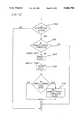
- FIG. 12is a flow chart showing the overall decision making steps involved in the present invention.
- FIG. 13is a flow chart showing the decision steps relating to speed sensing.
- FIG. 14is a flow chart showing the decision steps relating to approach angle sensing.
- FIG. 1illustrates a forklift truck of the type including a wire guidance system
- the truckmay include a power unit 10, a platform assembly 20, and a load handling assembly 30.
- the power unit 10includes a power source, such as a battery unit 12, a pair of load wheels 14 positioned under the platform assembly, a pair of steered wheels 15 (FIG. 2) positioned under the rear end of the power unit 10 with each wheel being driven by a traction motor 16, a mast 17 on which the platform assembly 20 rides, and a power unit electronic control unit 18 (FIG. 2).
- a power sourcesuch as a battery unit 12
- load wheels 14positioned under the platform assembly
- a pair of steered wheels 15(FIG. 2) positioned under the rear end of the power unit 10 with each wheel being driven by a traction motor 16, a mast 17 on which the platform assembly 20 rides
- a power unit electronic control unit 18FIG. 2
- the platform assembly 20includes a seat 22 from which the operator can control a steering tiller 23, traction motor control 24, brake pedals 25 and forklift controls 26.
- the platform assembly 20includes an electronics package 28 which is interconnected with the power unit electronics package 18 by means of appropriate electrical cables.
- the load handling assembly 30includes a pair of lift forks 32 which may be raised and lowered, and also rotated relative to the platform assembly by the controls 26.
- the power unit 10supports two sensor bars 40 and 42.
- Sensor bar 40is located between the steerable wheels while the sensor bar 42 is placed between the load wheels 14. Both sensor bars are designed to detect a wire 50 embedded in the floor of the warehouse.
- the embedded wire 50is placed down the center of the narrow aisles between the storage racks 51 in a warehouse.
- a line driver 52causes current to pass through the wire at a frequency in the range of from 4-12 kHz.
- the wire 50is embedded in a saw cut 53 made in the floor 54, and it is held in place by epoxy 55 which fills the remainder of the cut after the wire has been placed in the bottom thereof.
- the wirewill radiate a signal, shown by the dashed lines 56 in FIG. 5, which signal may be detected by sensor coils carried by either or both of the sensor bars 40 or 42.
- each of the sensor bars 40, 42four sensor coils 60 are carried by each of the sensor bars 40, 42.
- the axis of each coilis horizontal to the floor 54.
- Coil 60ais placed six inches to the left of the center line of the sensor bar, coil 60b is three inches to the left, coil 60c is three inches to the right, and coil 60d is 6 inches to the right of the center line.
- the centers of each coilare a nominal 4 inches above the wire 50.
- Each coil 60is approximately 1 inch in length, and 1/2inch in diameter.
- the steering tiller 23, traction motor control 24, brakes 25 and fork lift controls 26, as well as the other controls on the platform assembly,are provided with position sensors encoders and switches, and signals from these devices are transmitted to the electronic control package 18 located in the power unit 10.
- the platform assembly 20includes a steering encoder 23a, steering indicator lights 23b to show the operator which direction the wheels have been turned, a guidance switch 65, a signal strength light 65, guidance indicator lights 67, and an alarm or horn 68.
- a serial link 70electrically connects the platform electronic control package 28 to the power unit electronic control package 18, which also receives further input signals from a steering feedback encoder 72 which indicates the actual position of the steering wheels, the steered wheeled sensor bar 40, the load wheel sensor bar 42, and the brake switch 74. It provides output signals to control the steering servomotors 81 and 82 through a steering motor control circuit 80, a steering contactor 84, a brake relay 85, and a traction motor control circuit 86.
- a microcomputer wire guidance system 90includes a microprocessor 92 that is provided with inputs from two sensor amplifiers 95a and 95b, and other inputs from the steered wheel position sensor 72, the steering encoder 23a, the guidance control switch 65, vehicle speed information from tachometers 96 associated with each of the steered wheels 15, and memory circuit 97 (which include predetermined speed and angle of approach limits). Outputs from the microcomputer 90 are provided to the traction motor control 86 for controlling the speed of the vehicle, to brake control 100 and to the steering servomotor control 80. Other outputs are provided to indicate to the operator when the vehicle is near an operating wire, that is, a wire which has the proper signal for use in a guidance system by means of the alarm horn 68 and field strength indicator light 66.
- the microcomputer 90When the guidance selector switch 65 is in the manual position, the operator controls the steering of the vehicle directly by means of the steering tiller 23. When the guidance selector switch 65 is placed in the automatic position, the microcomputer 90 will automatically enter the search mode, and when either sensor 40 or 42 detects the guidance signal, the microcomputer 90 will automatically take the vehicle into an Acquisition Mode where the vehicle is guided into alignment with the wire. Once the vehicle is properly aligned, the microcomputer 90 will go into an Automatic Tracking Mode where the vehicle alignment is maintained automatically under computer control.
- Each of the sensor coilsis connected to its own amplifier 95, as illustrated in FIG. 8. Since the magnitude of the sinusoidal signal sensed by each sensor coil 60 is a function of the distance of that coil from the wire 50, the sensor amplifier 95 includes a dynamic clipper circuit to reduce the amount of unwanted noise and other signals not emanating from the wire itself. The output of the sensor amplifier 95 is then applied to the wire guidance computer 92.
- FIG. 8illustrates several components of the microcomputer 92 used in processing the signal with respect to a single sensor coil 60.
- Oneis an analog to digital (A/D) converter 105, which provides a digital representation of the voltage sensed by the sensor coil.
- a secondis the gain factor memory 110 and multiplier circuit 115.
- the raw voltage output from the A/D 105is normalized by multiplying it by a gain factor established for that coil during a calibration procedure.
- the output of the multiplier 115is then compared by circuit 120 to the voltages in a look up table 125, which holds previously determined voltage-to-distance data.
- the output of the comparing circuit 120therefore represents the distance of that particular coil from the wire 50.
- the look up table 125holds only a limited number of data points (only 64 in the preferred embodiment), and therefore a straightforward interpolation procedure is used to obtain distance measurements when the voltage output of a coil falls between these data points.
- the relationship between voltage and distanceis represented in the curve of FIG. 9.
- the microcomputer 92will therefore sense the output of each of the sensor coils 60 individually, and by reference to a voltage level established during a calibration procedure, and the voltage-to-distance data in the look up table 125, the distance of the sensor coil from the buried wire ca then be calculated.
- each sensor bar 40, 42is used as the reference from which later vehicle distance measurements are calculated.
- the distance of each coil from the wireis determined, as described above, and the coil that has the highest output (the coil closest to the wire) is identified.
- the region where the wire is either located or closest tois identified by checking the output of adjacent coils.
- the sensor barsare divided into five separate regions: Region 1 is to the left of coil 60a (as viewed in the drawing), Region 2 is between coils 60a and 60b, Region 3 is between coils 60b and 60c, Region 4 is between coils 60c and 60d, and Region 5 is to the right of coil 60d. If the wire 50 is in the position shown by the line 50a, it is clearly in Region 5, and if it is in the position shown by line 50b, it is in Region 3.
- the distance D of the wire relative to the sensor bar's center point 130(referred to hereinafter as either XFRONT for bar 40 or XREAR for bar 42) is calculated from one of the following formulas.
- Dis the distance (XFRONT or XREAR) in units of 1/64 inch of the wire from the center point 130;
- Xl, X2, X3, and X4are the distance values for coils 60a, 60b, 60c, and 60d, respectively;
- SCis a scale constant. It is clear that when the wire is to the left of the center point, the distance value D is negative. Using the dimensions given in FIG. 4 for a sensor bar, the scale constant SC will be 4.5 inches.
- a weight factor routinewill be used to determine the distance of the coils in a region from the wire since accuracy of the coil's voltage to distance curve deteriorates, as illustrated in FIG. 9.
- the position of the vehicle's virtual point 140may be calculated, and also the angle of the vehicle's axis relative to the wire (assuming the vehicle is in motion), by using one of the following procedures.
- the first procedure, V1CALCis used when both sensor bars are reading the wire; the second procedure, V2CALC, is used when only one sensor bar senses the presence of the wire. In either procedure, the result is a measurement of the vehicle's angle and distance from the buried wire 50.
- XMEASis the measured distance from the virtual point 140 to the wire
- AFSis the scaled value of the distance between the load wheel and front sensor bar divided by the distance between the sensor bars
- TMEASis the measured value of the angle of the vehicle relative to the wire
- SENDISis a scale value used in converting units from distance to radians.
- TDEADis the dead reckoning value for the truck angle
- TACTis the filtered value of the truck angle, in radians
- NEWDis the new value of the distance moved during the present pass
- TWHEELis the value of the wheel angle
- WBis the value for the wheel base, in inches
- XDEADis the distance from the wire during dead reckoning
- XACTis the filtered value of the truck virtual reference center position with reference to the wire.
- TOFFSis the truck angle offsets due to sensors
- K1, K2, K4 and K6are constants.
- V2CALC PROCEDURE(ONE SENSOR DATA KNOWN)
- XFOis the distance between the front sensor bar 40 and the wire during the previous pass
- ARLTis the scaled value of the distance between the load wheel and the rear sensor divided by the wheel base
- DISTis the value of the distance moved since the last microcomputer update.
- Nis a sample count used in the averaging of a single sensor and AF and AR are constants: AF is the distance from the load wheel to the steered wheel sensor bar and AR is the distance from the load wheel to the load wheel sensor bar, in inches.
- ABSXF and ABSXRare the absolute filtered values of XFRONT and XREAR, respectively.
- CMDU, CMDare intermediate steered wheel commands which include the position (XACT) and angle (TACT) of the vehicle
- OCMDis the output command
- Glis the feedback gain for the steered wheel angular position (volts/radians)
- G2is the feedback gain for the vehicle angular position (volts/radians)
- G3is the feedback gain for the vehicle's position (XACT) (volts/inches).
- the total steered wheel output command OCMDwhich is a pulse width modulated signal applied to the steered wheel motors, is therefore a combination of signals, taking into account the vehicle's location and angle of the steered wheels.
- These formulacomprise the microcomputer based mathematical representation of the wire guidance response system.
- the inputs to these equationsinclude the vehicle's position and angular displacement from the guide wire (derived from sensor coil values), steered wheel angle (derived from the steered wheel encoder 23a), and the distance traveled since the last microcomputer update (from equations V1CALC, V2CALC, LIB4, LIB5 and XTRANS).
- the output from these equationsis an error signal which is converted to a pulse width modulated steering command OCMD (from equations LIB2 and TCMD) which positions the steered wheels to a location in order to maintain the straight line wire guide travel condition.
- a simulated wire guide path signalis provided by a wire 132 connected to generator 135 (FIGS. 8 and 10) that produces a 7 kHz signal during calibration.
- the wireis permanently placed near each of the sensor coils and when the generator 135 is activated, a test signal is generated. The signal thus produced is detected by the sensor coils, with the output of each coil being processed by its respective amplifier. If the output of each is above a predetermined magnitude during the test, then a signal is generate indicating that the guidance hardware is present and working.
- the peak coil valuesare monitored, and if any coil indicates that it is saturated, a signal is generated to warn the operator to verify that the proper equipment is installed and that the wire guidance signal is functioning properly.
- the wire tracking modeif any sensor coil reads a value in excess of the value detected during the calibration, the vehicle's brakes will be applied and the wire guidance system shut down.
- the LIB5 formulasare used to calculate the position of the vehicle based on previous location, speed and the present wheel angle.
- the guidance equationscontinue to drive the vehicle toward the centerline of the wire.
- the vehicleIn order to enter the overshoot mode, the vehicle must not have been in the tracking mode. Also, the angle of the vehicle relative to the wire must be below a predetermined maximum limit. To remain in the overshoot mode, the vehicle must be making progress toward wire acquisition by decreasing the distance to the wire during each cycle. During an overshoot, when the vehicle approaches and then passes over the wire, the position information is not as accurate as when the vehicle is aligned with the wire, and the speed of the vehicle will be limited to 1.5 mph.
- the speed of the vehicleis monitored by a pair of tachometers 96, and the angle of approach of the vehicle (TACT) is determined by the microcomputer from the equations described above.
- the microcomputeralso senses the position of the guide switch 65. If the switch 65 is in the Automatic position, indicating that wire guidance has been selected, and the sensors 40 and/or 42 have detected the wire 50, then the decision path of FIG. 12 will be followed.
- the acquisition mode decision 200is engaged when the wire has been detected.
- the angle/speed complete decision flags 210are complete when both the speed and angle flags from the test of FIGS. 13 and 14 are complete.
- the next decisionis the speed test 220, shown more fully in FIG. 13. Upon successful completion of this test, the speed flag 222 is set.
- angle of approach test 230is shown more fully in FIG. 14. Upon successful completion of this test, angle flag 232 is set. Failure of either test will result in shutdown of the guidance system and the application of the vehicle's brakes. To release the brakes, the operator must toggle the guidance switch 65.
- the vehicle's brakes 100will be applied. Also, the wire guidance mode will be disabled and the steering control returned to the operator on the platform assembly.
Landscapes
- Physics & Mathematics (AREA)
- Engineering & Computer Science (AREA)
- Electromagnetism (AREA)
- Aviation & Aerospace Engineering (AREA)
- Radar, Positioning & Navigation (AREA)
- Remote Sensing (AREA)
- General Physics & Mathematics (AREA)
- Automation & Control Theory (AREA)
- Control Of Position, Course, Altitude, Or Attitude Of Moving Bodies (AREA)
Abstract
Description
______________________________________ If inRegion 1, D = -(X1 + X2)/2 - SC If inRegion 2, D = (X2 - X1)/2 - SC If inRegion 3, D = (X2 - X3)/2 If inRegion 4, D = (X3 - X4)/2 + SC If inRegion 5, D = (X3 + X4)/2 + SC ______________________________________
______________________________________ V1CALC Procedure (two sensor bar data known) ______________________________________ XMEAS = AFS(XFRONT - XREAR) - XFRONT TMEAS = (XREAR - XFRONT) / SENDIS ______________________________________
______________________________________ LIB5 Formulas: ______________________________________ TDEAD = TACT(OLD) + [NEWD * (SIN(TWHEEL))]/WB XDEAD = XACT(OLD) + [NEWD * (COS(TWHEEL)) * SIN(TDEAD))] ______________________________________
______________________________________ LIB4 Formulas: ______________________________________ if TMEAS + TOFFS = TDEAD TACT = TDEAD if TMEAS + TOFFS > TDEAD TACT = TDEAD + [K6 * (TMEAS + TOFFS - TDEAD) + K2] if TMEAS + TOFFS < TDEAD TACT = TDEAD + [K6 * (TMEAS + TOFFS - TDEAD) - K2] if XMEAS + XOFFS=XDEAD XACT = XDEAD if XMEAS + XOFFS > XDEAD = XDEAD + [K1 * (XMEAS + XOFFS - XDEAD) + K4] if XMEAS + XOFFS < XDEAD = XDEAD + [K1 * (XMEAS + XOFFS - XDEAD) - K4] ______________________________________
______________________________________ CA = XFRONT - XFO + CB CB = DIST * SIN(TWHEEL) * AFLT CD = DIST * COS(TWHEEL) ______________________________________
______________________________________ CA = XREAR - XRO + CB CB = DIST * SIN(TWHEEL) * ARLT CD = DIST * COS(TWHEEL) ______________________________________
______________________________________ TMEAS = [CA * COS(TMEAS)] + CB + [CD * SIN(TMEAS)] TACT = [TACT + 1/WB * DIST * SIN (THWEEL)] * [(N-1)/N] - TMEAS/N XMEAS(F) = -AF * SIN(TMEAS) - XFRONT * COS(TMEAS) XMEAS(R) = -AR * SIN(TMEAS) - XREAR * COS(TMEAS) XACT = [XACT + DIST * COS(TWHEEL) * SIN(TACT)] * [(N-1)/N] - TMEAS/(N) ______________________________________
ABSXF =-XACT -(AF * TACT)
ABSXR =-XACT -(AR * TACT)
CMDU,CMD [FORWARD]=G3 (XACT +XOFSET) +G2(TACT +TOFSET)
[REVERSE]=G3(XACT +XOFSET) -G2(TACT +TOFSET)
OCMD =(G1 * TWHEEL) +(CMDU,CMD)
Claims (4)
Priority Applications (1)
| Application Number | Priority Date | Filing Date | Title |
|---|---|---|---|
| US07/446,847US5068790A (en) | 1989-12-06 | 1989-12-06 | Wire guidance control system |
Applications Claiming Priority (1)
| Application Number | Priority Date | Filing Date | Title |
|---|---|---|---|
| US07/446,847US5068790A (en) | 1989-12-06 | 1989-12-06 | Wire guidance control system |
Publications (1)
| Publication Number | Publication Date |
|---|---|
| US5068790Atrue US5068790A (en) | 1991-11-26 |
Family
ID=23774046
Family Applications (1)
| Application Number | Title | Priority Date | Filing Date |
|---|---|---|---|
| US07/446,847Expired - LifetimeUS5068790A (en) | 1989-12-06 | 1989-12-06 | Wire guidance control system |
Country Status (1)
| Country | Link |
|---|---|
| US (1) | US5068790A (en) |
Cited By (21)
| Publication number | Priority date | Publication date | Assignee | Title |
|---|---|---|---|---|
| US5164648A (en)* | 1990-07-10 | 1992-11-17 | Daifuku Co., Ltd. | Equipment for transporting a load |
| US5489828A (en)* | 1992-03-13 | 1996-02-06 | Fiat Om Carrelli Elevatori S.P.A. | Electric drive system in lift trucks |
| US5638387A (en)* | 1994-01-19 | 1997-06-10 | Fiat Om Carrelli Elevatori S.P.A. | Electrically driven lift truck |
| US5687081A (en)* | 1994-12-30 | 1997-11-11 | Crown Equipment Corporation | Lift truck control system |
| US5821718A (en)* | 1996-05-07 | 1998-10-13 | Chrysler Corporation | Robotic system for automated durability road (ADR) facility |
| US5838562A (en)* | 1990-02-05 | 1998-11-17 | Caterpillar Inc. | System and a method for enabling a vehicle to track a preset path |
| US5867089A (en)* | 1996-09-03 | 1999-02-02 | Chrysler Corporation | Base-to-remotely controlled vehicle communications for automated durability road (ADR) facility |
| US5906647A (en)* | 1996-09-03 | 1999-05-25 | Chrysler Corporation | Vehicle mounted guidance antenna for automated durability road (ADR) facility |
| US5908454A (en)* | 1996-09-03 | 1999-06-01 | Chrysler Corporation | Operator interface for automated durability road (ADR) facility |
| US5913945A (en)* | 1996-05-02 | 1999-06-22 | Daimlerchrysler Corporation | Pedal linkage for robotic control of vehicle |
| US5938705A (en)* | 1996-09-03 | 1999-08-17 | Chrysler Corporation | Vehicle controller (VCON) for automated durability road (ADR) facility |
| US5991674A (en)* | 1996-05-02 | 1999-11-23 | Chrysler Corporation | Floor shifter linkage for robotic control of vehicle |
| US6061613A (en)* | 1996-09-03 | 2000-05-09 | Chrysler Corporation | Base station for automated durability road (ADR) facility |
| US6141620A (en)* | 1996-09-03 | 2000-10-31 | Chrysler Corporation | Vehicle control system for automated durability road (ADR) facility |
| US6255793B1 (en) | 1995-05-30 | 2001-07-03 | Friendly Robotics Ltd. | Navigation method and system for autonomous machines with markers defining the working area |
| US20090000103A1 (en)* | 2007-06-28 | 2009-01-01 | Crown Equipment Corporation | Manufacturing cell and elements of the cell |
| EP2413214A1 (en)* | 2010-07-28 | 2012-02-01 | Deere & Company | Robotic mower boundary coverage system and robotic mower |
| US8694194B2 (en) | 2011-08-29 | 2014-04-08 | Crown Equipment Corporation | Vehicular navigation control interface |
| US8718860B2 (en) | 2011-08-29 | 2014-05-06 | Crown Equipment Corporation | Vehicle control limits |
| US9778656B2 (en) | 2011-08-29 | 2017-10-03 | Crown Equipment Corporation | Multimode vehicular navigation control |
| US11726491B2 (en) | 2018-02-20 | 2023-08-15 | The Raymond Corporation | Wire guidance and remote operation for material handling vehicles |
Citations (3)
| Publication number | Priority date | Publication date | Assignee | Title |
|---|---|---|---|---|
| US4530056A (en)* | 1982-10-28 | 1985-07-16 | Modular Automation Corp. | Automated guided vehicle system |
| US4626995A (en)* | 1984-03-26 | 1986-12-02 | Ndc Technologies, Inc. | Apparatus and method for optical guidance system for automatic guided vehicle |
| US4800977A (en)* | 1984-08-10 | 1989-01-31 | Jd-Technologie Ag | Control system for driving and steering driverless transport devices |
- 1989
- 1989-12-06USUS07/446,847patent/US5068790A/ennot_activeExpired - Lifetime
Patent Citations (3)
| Publication number | Priority date | Publication date | Assignee | Title |
|---|---|---|---|---|
| US4530056A (en)* | 1982-10-28 | 1985-07-16 | Modular Automation Corp. | Automated guided vehicle system |
| US4626995A (en)* | 1984-03-26 | 1986-12-02 | Ndc Technologies, Inc. | Apparatus and method for optical guidance system for automatic guided vehicle |
| US4800977A (en)* | 1984-08-10 | 1989-01-31 | Jd-Technologie Ag | Control system for driving and steering driverless transport devices |
Cited By (30)
| Publication number | Priority date | Publication date | Assignee | Title |
|---|---|---|---|---|
| US5838562A (en)* | 1990-02-05 | 1998-11-17 | Caterpillar Inc. | System and a method for enabling a vehicle to track a preset path |
| US5164648A (en)* | 1990-07-10 | 1992-11-17 | Daifuku Co., Ltd. | Equipment for transporting a load |
| US5489828A (en)* | 1992-03-13 | 1996-02-06 | Fiat Om Carrelli Elevatori S.P.A. | Electric drive system in lift trucks |
| US5638387A (en)* | 1994-01-19 | 1997-06-10 | Fiat Om Carrelli Elevatori S.P.A. | Electrically driven lift truck |
| US5687081A (en)* | 1994-12-30 | 1997-11-11 | Crown Equipment Corporation | Lift truck control system |
| US6984952B2 (en) | 1995-05-30 | 2006-01-10 | F Robotics Acquisitions Ltd. | Navigation method and system for autonomous machines with markers defining the working area |
| US6255793B1 (en) | 1995-05-30 | 2001-07-03 | Friendly Robotics Ltd. | Navigation method and system for autonomous machines with markers defining the working area |
| US6850024B2 (en) | 1995-05-30 | 2005-02-01 | F Robotics Acquisitions Ltd. | Navigation method and system for autonomous machines with markers defining the working area |
| US20050007057A1 (en)* | 1995-05-30 | 2005-01-13 | Friendly Robotics, Ltd. | Navigation method and system for autonomous machines with markers defining the working area |
| US20020140393A1 (en)* | 1995-05-30 | 2002-10-03 | Friendly Robotics, Ltd. | Navigation method and system for autonomous machines with markers defining the working area |
| US6417641B2 (en) | 1995-05-30 | 2002-07-09 | Friendly Robotics Ltd. | Navigation method and system for autonomous machines with markers defining the working area |
| US5913945A (en)* | 1996-05-02 | 1999-06-22 | Daimlerchrysler Corporation | Pedal linkage for robotic control of vehicle |
| US5991674A (en)* | 1996-05-02 | 1999-11-23 | Chrysler Corporation | Floor shifter linkage for robotic control of vehicle |
| US5821718A (en)* | 1996-05-07 | 1998-10-13 | Chrysler Corporation | Robotic system for automated durability road (ADR) facility |
| US5906647A (en)* | 1996-09-03 | 1999-05-25 | Chrysler Corporation | Vehicle mounted guidance antenna for automated durability road (ADR) facility |
| US6061613A (en)* | 1996-09-03 | 2000-05-09 | Chrysler Corporation | Base station for automated durability road (ADR) facility |
| US5938705A (en)* | 1996-09-03 | 1999-08-17 | Chrysler Corporation | Vehicle controller (VCON) for automated durability road (ADR) facility |
| US5908454A (en)* | 1996-09-03 | 1999-06-01 | Chrysler Corporation | Operator interface for automated durability road (ADR) facility |
| US5867089A (en)* | 1996-09-03 | 1999-02-02 | Chrysler Corporation | Base-to-remotely controlled vehicle communications for automated durability road (ADR) facility |
| US6141620A (en)* | 1996-09-03 | 2000-10-31 | Chrysler Corporation | Vehicle control system for automated durability road (ADR) facility |
| US8544159B2 (en) | 2007-06-28 | 2013-10-01 | Crown Equipment Corporation | Methods of manufacturing parts using a manufacturing cell |
| US20090000103A1 (en)* | 2007-06-28 | 2009-01-01 | Crown Equipment Corporation | Manufacturing cell and elements of the cell |
| US8108989B2 (en) | 2007-06-28 | 2012-02-07 | Crown Equipment Corporation | Manufacturing cell and elements of the cell |
| EP2413214A1 (en)* | 2010-07-28 | 2012-02-01 | Deere & Company | Robotic mower boundary coverage system and robotic mower |
| US8694194B2 (en) | 2011-08-29 | 2014-04-08 | Crown Equipment Corporation | Vehicular navigation control interface |
| US8718860B2 (en) | 2011-08-29 | 2014-05-06 | Crown Equipment Corporation | Vehicle control limits |
| US8892294B2 (en) | 2011-08-29 | 2014-11-18 | Crown Equipment Corporation | Vehicle control limits |
| US9002626B2 (en) | 2011-08-29 | 2015-04-07 | Crown Equipment Company | Vehicular navigation control interface |
| US9778656B2 (en) | 2011-08-29 | 2017-10-03 | Crown Equipment Corporation | Multimode vehicular navigation control |
| US11726491B2 (en) | 2018-02-20 | 2023-08-15 | The Raymond Corporation | Wire guidance and remote operation for material handling vehicles |
Similar Documents
| Publication | Publication Date | Title |
|---|---|---|
| US5068790A (en) | Wire guidance control system | |
| US5032994A (en) | Manual sensing of wire guidance signal | |
| US5068791A (en) | Distance and angle measurements in a wire guided vehicle | |
| US4162869A (en) | Unmanned conveying control system | |
| EP0658467B1 (en) | Guidewire controls for a manned, material handling vehicle | |
| EP0132908B1 (en) | Driverless vehicle and method of steering the same | |
| JP3378843B2 (en) | Correction device for position and direction of automatic guided vehicle | |
| CA2120218C (en) | Method and apparatus for sensing guidewire signals | |
| US5008604A (en) | Dynamic clipper for use in a vehicle guidance system | |
| JP3276096B2 (en) | Automatic guided vehicle control device | |
| JP2001202131A (en) | Automated guided vehicle | |
| JPH0412841B2 (en) | ||
| JP2712739B2 (en) | Steering angle control device for automatic guided vehicles | |
| JP3538503B2 (en) | Guidance control device for mobile vehicles | |
| JP2002182745A (en) | Travel controller for unmanned carrier | |
| JPH09269820A (en) | Vehicle guiding device | |
| JP3804142B2 (en) | Unmanned vehicle steering control method | |
| JPH09269833A (en) | Travel controller for vehicle | |
| JPH0222721Y2 (en) | ||
| JPH02222007A (en) | Attitude confirming device for unmanned carrier | |
| JPH0358104A (en) | Automatic control running device for vehicle | |
| JPH061249A (en) | Position sensor and electromagnetic induction type automated guided vehicle using the same | |
| JPH04257006A (en) | Course out detecting method for unmanned vehicle | |
| JP2590015Y2 (en) | Guideway device for electromagnetically guided vehicles | |
| JP2512975B2 (en) | Travel control device for automatic guided vehicles |
Legal Events
| Date | Code | Title | Description |
|---|---|---|---|
| AS | Assignment | Owner name:CROWN EQUIPMENT CORPORATION, OHIO Free format text:ASSIGNMENT OF ASSIGNORS INTEREST.;ASSIGNOR:WELLMAN, TIM A.;REEL/FRAME:005215/0755 Effective date:19891212 | |
| AS | Assignment | Owner name:CROWN CONTROLS CORPORATION, A CORP. OF NEVADA, NEV Free format text:ASSIGNMENT OF ASSIGNORS INTEREST.;ASSIGNOR:CROWN EQUIPMENT CORPORATION;REEL/FRAME:005280/0043 Effective date:19900328 | |
| STCF | Information on status: patent grant | Free format text:PATENTED CASE | |
| FEPP | Fee payment procedure | Free format text:PAYOR NUMBER ASSIGNED (ORIGINAL EVENT CODE: ASPN); ENTITY STATUS OF PATENT OWNER: LARGE ENTITY | |
| FPAY | Fee payment | Year of fee payment:4 | |
| FEPP | Fee payment procedure | Free format text:PAYER NUMBER DE-ASSIGNED (ORIGINAL EVENT CODE: RMPN); ENTITY STATUS OF PATENT OWNER: LARGE ENTITY Free format text:PAYOR NUMBER ASSIGNED (ORIGINAL EVENT CODE: ASPN); ENTITY STATUS OF PATENT OWNER: LARGE ENTITY | |
| FEPP | Fee payment procedure | Free format text:PAYOR NUMBER ASSIGNED (ORIGINAL EVENT CODE: ASPN); ENTITY STATUS OF PATENT OWNER: LARGE ENTITY Free format text:PAYER NUMBER DE-ASSIGNED (ORIGINAL EVENT CODE: RMPN); ENTITY STATUS OF PATENT OWNER: LARGE ENTITY | |
| FPAY | Fee payment | Year of fee payment:8 | |
| FEPP | Fee payment procedure | Free format text:PAYOR NUMBER ASSIGNED (ORIGINAL EVENT CODE: ASPN); ENTITY STATUS OF PATENT OWNER: LARGE ENTITY Free format text:PAYER NUMBER DE-ASSIGNED (ORIGINAL EVENT CODE: RMPN); ENTITY STATUS OF PATENT OWNER: LARGE ENTITY | |
| FPAY | Fee payment | Year of fee payment:12 | |
| REMI | Maintenance fee reminder mailed |