US5066900A - Dc/dc converter switching at zero voltage - Google Patents
Dc/dc converter switching at zero voltageDownload PDFInfo
- Publication number
- US5066900A US5066900AUS07/542,478US54247890AUS5066900AUS 5066900 AUS5066900 AUS 5066900AUS 54247890 AUS54247890 AUS 54247890AUS 5066900 AUS5066900 AUS 5066900A
- Authority
- US
- United States
- Prior art keywords
- transformer
- recited
- converter circuit
- switching means
- terminal
- Prior art date
- Legal status (The legal status is an assumption and is not a legal conclusion. Google has not performed a legal analysis and makes no representation as to the accuracy of the status listed.)
- Expired - Lifetime
Links
- 230000008878couplingEffects0.000claimsabstractdescription4
- 238000010168coupling processMethods0.000claimsabstractdescription4
- 238000005859coupling reactionMethods0.000claimsabstractdescription4
- 238000004804windingMethods0.000claimsdescription26
- 230000033228biological regulationEffects0.000abstractdescription2
- 238000004146energy storageMethods0.000abstractdescription2
- 230000001939inductive effectEffects0.000abstractdescription2
- 230000007704transitionEffects0.000abstractdescription2
- 239000003990capacitorSubstances0.000description26
- 239000011162core materialSubstances0.000description12
- 230000004907fluxEffects0.000description8
- 230000008901benefitEffects0.000description5
- 230000009977dual effectEffects0.000description3
- 230000000694effectsEffects0.000description3
- 238000012986modificationMethods0.000description3
- 230000004048modificationEffects0.000description3
- 230000008859changeEffects0.000description2
- 238000007599dischargingMethods0.000description2
- 238000010348incorporationMethods0.000description2
- 230000009286beneficial effectEffects0.000description1
- 239000002131composite materialSubstances0.000description1
- 230000003247decreasing effectEffects0.000description1
- 238000005516engineering processMethods0.000description1
- 238000009499grossingMethods0.000description1
- 238000002955isolationMethods0.000description1
- 230000005415magnetizationEffects0.000description1
- 230000004044responseEffects0.000description1
- 239000004065semiconductorSubstances0.000description1
Images


Classifications
- H—ELECTRICITY
- H05—ELECTRIC TECHNIQUES NOT OTHERWISE PROVIDED FOR
- H05B—ELECTRIC HEATING; ELECTRIC LIGHT SOURCES NOT OTHERWISE PROVIDED FOR; CIRCUIT ARRANGEMENTS FOR ELECTRIC LIGHT SOURCES, IN GENERAL
- H05B41/00—Circuit arrangements or apparatus for igniting or operating discharge lamps
- H—ELECTRICITY
- H02—GENERATION; CONVERSION OR DISTRIBUTION OF ELECTRIC POWER
- H02M—APPARATUS FOR CONVERSION BETWEEN AC AND AC, BETWEEN AC AND DC, OR BETWEEN DC AND DC, AND FOR USE WITH MAINS OR SIMILAR POWER SUPPLY SYSTEMS; CONVERSION OF DC OR AC INPUT POWER INTO SURGE OUTPUT POWER; CONTROL OR REGULATION THEREOF
- H02M3/00—Conversion of DC power input into DC power output
- H02M3/02—Conversion of DC power input into DC power output without intermediate conversion into AC
- H02M3/04—Conversion of DC power input into DC power output without intermediate conversion into AC by static converters
- H02M3/10—Conversion of DC power input into DC power output without intermediate conversion into AC by static converters using discharge tubes with control electrode or semiconductor devices with control electrode
- H02M3/145—Conversion of DC power input into DC power output without intermediate conversion into AC by static converters using discharge tubes with control electrode or semiconductor devices with control electrode using devices of a triode or transistor type requiring continuous application of a control signal
- H02M3/155—Conversion of DC power input into DC power output without intermediate conversion into AC by static converters using discharge tubes with control electrode or semiconductor devices with control electrode using devices of a triode or transistor type requiring continuous application of a control signal using semiconductor devices only
- H02M3/156—Conversion of DC power input into DC power output without intermediate conversion into AC by static converters using discharge tubes with control electrode or semiconductor devices with control electrode using devices of a triode or transistor type requiring continuous application of a control signal using semiconductor devices only with automatic control of output voltage or current, e.g. switching regulators
- H02M3/158—Conversion of DC power input into DC power output without intermediate conversion into AC by static converters using discharge tubes with control electrode or semiconductor devices with control electrode using devices of a triode or transistor type requiring continuous application of a control signal using semiconductor devices only with automatic control of output voltage or current, e.g. switching regulators including plural semiconductor devices as final control devices for a single load
- H—ELECTRICITY
- H02—GENERATION; CONVERSION OR DISTRIBUTION OF ELECTRIC POWER
- H02M—APPARATUS FOR CONVERSION BETWEEN AC AND AC, BETWEEN AC AND DC, OR BETWEEN DC AND DC, AND FOR USE WITH MAINS OR SIMILAR POWER SUPPLY SYSTEMS; CONVERSION OF DC OR AC INPUT POWER INTO SURGE OUTPUT POWER; CONTROL OR REGULATION THEREOF
- H02M3/00—Conversion of DC power input into DC power output
- H02M3/22—Conversion of DC power input into DC power output with intermediate conversion into AC
- H02M3/24—Conversion of DC power input into DC power output with intermediate conversion into AC by static converters
- H02M3/28—Conversion of DC power input into DC power output with intermediate conversion into AC by static converters using discharge tubes with control electrode or semiconductor devices with control electrode to produce the intermediate AC
- H02M3/325—Conversion of DC power input into DC power output with intermediate conversion into AC by static converters using discharge tubes with control electrode or semiconductor devices with control electrode to produce the intermediate AC using devices of a triode or a transistor type requiring continuous application of a control signal
- H02M3/335—Conversion of DC power input into DC power output with intermediate conversion into AC by static converters using discharge tubes with control electrode or semiconductor devices with control electrode to produce the intermediate AC using devices of a triode or a transistor type requiring continuous application of a control signal using semiconductor devices only
- H02M3/33569—Conversion of DC power input into DC power output with intermediate conversion into AC by static converters using discharge tubes with control electrode or semiconductor devices with control electrode to produce the intermediate AC using devices of a triode or a transistor type requiring continuous application of a control signal using semiconductor devices only having several active switching elements
Definitions
- This inventionrelates to DC/DC converters used in DC/DC and AC/DC power supplies, and more particularly to single ended, zero voltage switched DC/DC converters.
- Single ended DC/DC convertersare commonly classified as one of three classical topologies: the boost; the buck; and the buck-boost. These converters comprise various arrangements of a switch, a diode, an inductor and two capacitors. Dual circuits of these topologies also exist wherein two inductors and one capacitor appear.
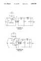
- FIGS. 1-2illustrate examples of DC/DC converters.
- FIG. 1illustrates a non-isolated, single switch buck-boost converter having a MOSFET power transistor Q1, inductor L1, diode D1, and capacitors C1 and C3.
- FIG. IAillustrates the dual circuit of the buck-boost converter wherein shunt capacitors C1 and C3 are replaced by series inductors L2 and L3, shunt inductor L1 by series capacitor C2, and series switch Q1 by shunt switch Q2.
- FIG. 2illustrates an isolated, single switch forward converter having transistor Q3, capacitors C4 and C5, diodes D2 and D3, inductor L4 and transformer T1.
- FIG. 2Aillustrates a forward converter with a second flux reset switch Q4 and capacitor C4.
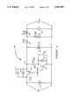
- FIG. 3illustrates a full wave series resonant converter wherein the output is controlled by varying the switching frequency.
- the resonant converter shownincludes transistors Q5 and Q6, capacitors C5, C6, and C7, diodes D5 and D6, inductors L5 and L6, and transformer T5.
- resonant converterscan exhibit either zero current or zero voltage switching, thereby significantly reducing the switching loss.
- the reactive componentsmust handle considerable power, sometimes amounting to several times the output power of the converter. This energy, which circulates through the components, can induce new losses which are greater than the decrease in switching loss.
- the operating voltage and/or RMS current stress on the semiconductor devicesis often increased.
- a DC/DC converterallows zero-voltage switching while maintaining the beneficial features of the basic topologies and avoiding the disadvantages relating to resonant converter schemes.
- the inventionmay be embodied in a non-isolated form, an isolated form, an integrated magnetic form, and a coupled magnetic form.
- the non-isolated formcomprises two switches, two diodes, two inductors, and at least one capacitor.
- the isolated formcomprises two switches, two diodes, a transformer, an inductor, and at least one capacitor.
- the integrated magnetic formcombines the transformer and the inductor of the isolated form on a common core with no mutual coupling.
- the coupled magnetic formintroduces magnetic reluctance in the common flux paths of the integrated magnetic elements causing the output ripple current to be greatly reduced.
- An additional embodiment of the inventionincludes a transformer having a plurality of secondary windings. Each of the secondary windings is connected to output circuitry which includes a plurality of output lines where each output line provides an output DC voltage.
- energy stored in the magnetic elementsis transferred to discharge the capacitance across each switch prior to closing the switch. Since the voltage across each switch is approximately zero as it is closed, switching loss is minimized. Hence, high converting efficiency may be realized.
- FIG. 1Aillustrates a non-isolated, single switch buck-boost converter.
- FIG. 1Billustrates a dual circuit of the buck-boost converter.
- FIG. 2illustrates an isolated, single switch forward converter.
- FIG. 2Aillustrates a forward converter with a second flux reset switch and capacitor.
- FIG. 3illustrates a full wave series resonant converter wherein control of the output requires changing the switching frequency.
- FIG. 4illustrates a zero voltage switching converter in accordance with the invention.
- FIG. 4Aillustrates current and voltage waveforms in accordance with the operation of the invention.
- FIG. 5illustrates an isolated embodiment of the invention with accompanying waveforms in FIGS. 5A and 5B showing variations from FIG. 4A.
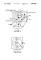
- FIG. 6illustrates a transformer combined with an inductor and in FIG. 6A its magnetic circuit to form an integrated magnetic embodiment of the isolated converter.
- FIGS. 7 and 7Aillustrate a transformer combined with an inductor to form a coupled magnetic embodiment of the isolated converter wherein output ripple current is reduced by added magnetic coupling as shown in the waveforms in FIG. 7B.
- FIG. 8illustrates a multiple output line embodiment of the invention.
- a zero voltage switching converter 10is shown in FIG. 4.
- a capacitor 11is connected across input terminals of converter 10 which receive a DC voltage.
- a transistor 12switches input power to the remainder of converter 10 in response to a control signal.
- transistor 12is a power MOSFET characterized with an intrinsic capacitance 13 and an intrinsic body diode 14 shunted across the source and drain of transistor 12.
- Capacitance 13also includes any discrete lumped capacitance or stay capacitance across transistor 12.
- diode 14may be a discrete device rather than an intrinsic body diode of transistor 12.
- An inductor 15is connected to the drain of transistor 12 and receives input power when transistor 12 is "on”.
- a capacitor 20 and a transistor (FET) 21are connected in series across inductor 15.
- An intrinsic capacitance 22 and a diode 23are shunted across the source and drain of transistor 21.
- Diodes 24 and 25are connected to inductor 15 and to a second inductor 26.
- Capacitor 27is connected across the output terminals of converter 10.
- converter 10The transfer function of converter 10 is easily derived since, in order to maintain flux balance under steady state conditions, the volt-second product impressed on inductor 15 during the on time of transistor 12 must equal the volt-second product during the off time, or:
- capacitor 20is considered to be large such that V c20 is constant over an operating cycle in spite of charge and discharge current.
- the output voltageis the time ratioed average of the voltage across capacitor 20 (V c20 ) during the off time of transistor 12 while diode 24 is conducting.
- the output voltageis given by:
- This voltage transfer functionis the same as that of the forward converter of FIG. 2.
- capacitor 20has been considered large to simplify the above description, it should be noted that capacitor 20 in accordance with the invention may be relatively small such that V C20 is not constant over an operating cycle.
- transistor 12is first turned on by the control and input voltage is applied to the winding of inductor 15.
- Diode 24is reverse biased during this time and energy is not transferred from input to output. This period is the first phase of operation shown as time period I in FIG. 4A.
- transistor 12is turned off.
- the stored magnetic energy in inductor 15maintains the flow of current in the same direction, charging capacitance 13 which shunts transistor 12. A portion of the current also flows through capacitor 20 and discharges capacitance 22 which shunts transistor 21.
- diode 24becomes forward biased, and consequently a further portion of the current of inductor 15 begins to flow to the output through diode 24. Current does not flow through diode 25 since it is reverse biased.
- the remaining current in inductor 15continues charging capacitance 13 and capacitance 22 until the voltage at node X equals the voltage across capacitor 20, at which time diode 23 begins to conduct.
- transistor 21is approximately zero when diode 23 begins to conduct and charge does not accumulate across capacitance 22. The excess current in inductor 15 continues to transfer to charge capacitor 20. During this period (Period II), transistor 21 is turned on by the control circuit. Thus, since the voltage across transistor 21 is approximately zero when turned on, minimal switching loss occurs. This completes the second phase of operation shown as period II in FIG. 4A.
- inductor 15 and inductor 26combine at node X, discharging capacitor 13 and charging capacitor 22 until the voltage at node X equals zero.
- the current in inductor 26is then shunted through diode 25 since diode 24 is reverse biased
- the remaining current in inductor 15continues to discharge capacitor 13 until diode 14 conducts. At this time, any remaining energy in inductor 15 is returned to the input.
- the voltage across transistor 12is approximately zero since charge does not accumulate across capacitance 13. This completes phase four, shown as period IV in FIG. 5.
- the control circuitagain turns on transistor 12 to begin phase one of operation. It should be noted that since only a small voltage is impressed across transistor 12 when it is turned on, minimal switching loss occurs.
- the two switch, DC/DC converter 10thus provides sufficient inductive energy storage at the termination of the "on" period of each switch to alter the charge on the intrinsic and stray capacitance of the combination of switches producing zero voltage across the alternate switch prior to its turn on.
- the short dead-band between the turn on pulses provided by the control circuitallows time for this transition.
- the energy stored in the capacitance of the switchesis returned to the source and load rather than being dissipated in the switching devices. This greatly improves the efficiency of the converter, particularly when operating at high frequency.
- the topology of converter 10provides other characteristics in addition to zero voltage switching such as operability at a constant frequency with pulse-width-modulation for regulation and quasi-square wave output current.
- a second embodiment of the inventionis constructed by replacing inductor 15 with transformer 30.
- the circuit of FIG. 5is an isolated DC/DC converter in accordance with the invention.
- a gap in the magnetic path of transformer 30sets the primary winding reactance equal to inductor 15 of FIG. 4.
- transformer 30has a dot at one terminal of the primary coil and a dot at one terminal of the secondary coil.
- a current entering the dotted terminal of one coilproduces an open circuit voltage between the terminals of the second coil which is sensed in the direction indicated by a positive voltage reference at the dotted terminal of this second coil.
- the isolated converteris similar to that of the non-isolated converter described above.
- the waveform of FIG. 5illustrates the current flowing through the primary of transformer 30.
- FIG. 5allows zero voltage switching in a manner similar to the nonisolated circuit of FIG. 4.
- Intrinsic capacitance 33 shunting transistor 32is discharged by energy stored in the primary of transformer 30.
- Diode 34prevents charge build-up in capacitance 33 before transistor 32 turns on.
- intrinsic capacitance 34 shunting transistor 35is discharged by energy stored in the primary of transformer 30 and in inductor 31 before the control turns on transistor 35. Hence, zero voltage switching is achieved and switching loss is minimized.
- the converter of FIG. 5has other advantages. Dielectric isolation between input and output is achieved.
- the output voltagemay be changed with respect to the input voltage in accordance with the transformer turns ratio N S /N P .
- the input currentmay also be changed with respect to the output current in accordance with the turns ratio.
- incorporation of the transformer leakage reactance into the inductance of the primary of transformer 30 and into inductor 31avoids the typical energy loss due to leakage reactance.
- Incorporation of the transformer winding capacitance into the intrinsic and distributed capacitance at node Xavoids loss due to winding capacitance since energy charging the capacitance positively transfers to charge the capacitance negatively rather than dissipating.
- FIG. 5Ashows a waveform of the primary winding current for an ideal transformer.
- FIG. 5Bshows the effect of leakage inductance on the waveform when a non-ideal transformer is used.
- the leakage inductancebeneficially alters the peak to average current ratio, thereby reducing stress on components.
- a third embodiment of the inventionis constructed by combining transformer 30 and inductor 31 of FIG. 5 on a common magnetic core 40 as shown in FIG. 6.
- the polarity of voltages, currents, and windingsis such that the DC components of magnetic flux from the transformer leg and the inductor leg add to the third leg of the core, while the AC components of magnetic flux from the transformer leg and inductor leg subtract in the third leg.
- several other advantages of this embodimentare achieved. Due to the sharing of core material, the volume of the core is reduced and therefore the total core losses are proportionally reduced. In addition, since losses in magnetic cores are due only to the AC flux, the subtraction of flux in the third leg further reduces the loss in this portion of the core. Finally, the multiplicity of components is reduced.
- a fourth embodiment of the inventionis constructed by inserting a magnetic reluctance (gap) 50 in the third leg of composite core 40, as shown in the integrated transformer of FIG. 7.
- the effectis such that during the conduction time of transistor 35 (interval I) energy is transferred from the primary of the transformer to the inductor leg, and the rate of decrease of current in the inductor and therefore diode 36 and the output circuits is abated and can be zero.
- transistor 32during the conduction of transistor 32 (interval III), energy is transferred uniformly over the interval and the current in the inductor and therefore diode 37, the transformer secondary and the output circuits exhibits less change and can be constant.
- the benefitsare decreased ripple current in the output, reduced stress on the output filter capacitor 38 and improved smoothing of the output voltage.
- the current in the diodes and the loadis demonstrated by the wave-shapes accompanying FIG. 7 and can be compared with the similar wave-shapes of FIG. 4A.
- the effectis defined mathematically for the interval I by the following equations, and can be similarly demonstrated for interval III by those skilled in the art.
- the ripple current in the output circuitvanishes.
- the air gapscan be chosen for this to occur at midpoint conditions, minimizing the ripple over the operating range.
- a multiple output line embodiment of the invention as shown in FIG. 8includes a transformer 80 having a plurality of secondary windings S-1 through S-N. During operation, output voltages V out1 through V outN are provided at output lines of the converter. Operation of the circuit is similar to the circuit of FIG. 5, and similar components are numbered identically.
- the plurality of inductors 31-1 through 31-Nmay be combined on a common core.
- transformer 80 and the plurality of inductors 31-1 through 31-Nmay be integrated together on a common core.
- the common coremay have three legs each containing a magnetic gap.
- Discrete capacitive elementsmay be connected in parallel across each of the switching transistors (i.e. transistor 33 and 34) in order to reduce the rate of change of voltage across the switching devices.
- discrete inductancemay be connected in series with the primary or secondary windings of the transformer incorporated within each of the isolated embodiments of the invention.
Landscapes
- Engineering & Computer Science (AREA)
- Power Engineering (AREA)
- Dc-Dc Converters (AREA)
- Amplifiers (AREA)
- Input Circuits Of Receivers And Coupling Of Receivers And Audio Equipment (AREA)
- Details Of Television Scanning (AREA)
Abstract
Description
V.sub.in ×t.sub.on V.sub.C20 ×t.sub.off (1)
V.sub.out =V.sub.c20 ×t.sub.off /(t.sub.on +t.sub.off) (2)
V.sub.out =V.sub.in ×t.sub.on /(t.sub.on +t.sub.off) (3)
N.sub.p I.sub.p +N.sub.s I.sub.s =Φ.sub.1 R.sub.1 +(Φ.sub.1 +Φ.sub.2)R.sub.3 (1)
N.sub.L I.sub.L =Φ.sub.2 R.sub.2 +(Φ.sub.1 +Φ.sub.2)R.sub.3 (2)
N.sub.L dI.sub.L /dt=R.sub.3 dΦ.sub.1 /dt+(R.sub.2 +R.sub.3) dΦ.sub.2 /dt (3)
V.sub.in =-E.sub.p =N.sub.p dΦ.sub.1 /dt; and V.sub.out =-N.sub.L dΦ.sub.2 /dt.
(V.sub.in /N.sub.P)R.sub.3 =(V.sub.out /N.sub.L)(R.sub.2 +R.sub.3) (4)
V.sub.out =V.sub.in (N.sub.S /N.sub.P)((T.sub.on /(t.sub.on +t.sub.off)) (5)
R.sub.3 /(R.sub.2 +R.sub.3)=σ (6)
Claims (19)
Priority Applications (13)
| Application Number | Priority Date | Filing Date | Title |
|---|---|---|---|
| US07/542,478US5066900A (en) | 1989-11-14 | 1990-06-22 | Dc/dc converter switching at zero voltage |
| IE370790AIE71049B1 (en) | 1989-11-14 | 1990-10-16 | DC/DC switching converter circuit |
| AU64703/90AAU636400B2 (en) | 1989-11-14 | 1990-10-18 | Dc/dc converter switching at zero voltage |
| CA002028453ACA2028453A1 (en) | 1989-11-14 | 1990-10-24 | Dc/dc converter switching at zero voltage |
| KR1019900018231AKR100186776B1 (en) | 1989-11-14 | 1990-11-12 | Dc/dc switching converter circuit |
| NO90904926ANO904926L (en) | 1989-11-14 | 1990-11-13 | DC POWER CONVERSION WITH ZERO CIRCUIT CONVERSION. |
| EP90312367AEP0428377B1 (en) | 1989-11-14 | 1990-11-13 | DC/DC switching converter circuit |
| ES90312367TES2024394A4 (en) | 1989-11-14 | 1990-11-13 | DC / DC CONVERTER CIRCUIT. |
| AT90312367TATE132671T1 (en) | 1989-11-14 | 1990-11-13 | DC VOLTAGE SWITCHING CONVERTER CIRCUIT |
| DE199090312367TDE428377T1 (en) | 1989-11-14 | 1990-11-13 | DC VOLTAGE TRANSFORMER CIRCUIT. |
| DE69024614TDE69024614T2 (en) | 1989-11-14 | 1990-11-13 | DC switching converter circuit |
| JP2308431AJP2875879B2 (en) | 1989-11-14 | 1990-11-14 | DC / DC switching converter circuit |
| JP10143720AJPH10327577A (en) | 1989-11-14 | 1998-05-26 | Dc/dc switching converter circuit |
Applications Claiming Priority (2)
| Application Number | Priority Date | Filing Date | Title |
|---|---|---|---|
| US07/436,394US4959764A (en) | 1989-11-14 | 1989-11-14 | DC/DC converter switching at zero voltage |
| US07/542,478US5066900A (en) | 1989-11-14 | 1990-06-22 | Dc/dc converter switching at zero voltage |
Related Parent Applications (1)
| Application Number | Title | Priority Date | Filing Date |
|---|---|---|---|
| US07/436,394Continuation-In-PartUS4959764A (en) | 1989-11-14 | 1989-11-14 | DC/DC converter switching at zero voltage |
Publications (1)
| Publication Number | Publication Date |
|---|---|
| US5066900Atrue US5066900A (en) | 1991-11-19 |
Family
ID=27030942
Family Applications (1)
| Application Number | Title | Priority Date | Filing Date |
|---|---|---|---|
| US07/542,478Expired - LifetimeUS5066900A (en) | 1989-11-14 | 1990-06-22 | Dc/dc converter switching at zero voltage |
Country Status (11)
| Country | Link |
|---|---|
| US (1) | US5066900A (en) |
| EP (1) | EP0428377B1 (en) |
| JP (2) | JP2875879B2 (en) |
| KR (1) | KR100186776B1 (en) |
| AT (1) | ATE132671T1 (en) |
| AU (1) | AU636400B2 (en) |
| CA (1) | CA2028453A1 (en) |
| DE (2) | DE69024614T2 (en) |
| ES (1) | ES2024394A4 (en) |
| IE (1) | IE71049B1 (en) |
| NO (1) | NO904926L (en) |
Cited By (93)
| Publication number | Priority date | Publication date | Assignee | Title |
|---|---|---|---|---|
| US5126651A (en)* | 1991-07-26 | 1992-06-30 | Motorola, Inc. | Gate drive circuit for a synchronous rectifier |
| US5224025A (en)* | 1992-04-21 | 1993-06-29 | Wisconsin Alumni Research Foundation | Forward converter with two active switches and unity power factor capability |
| US5262930A (en)* | 1992-06-12 | 1993-11-16 | The Center For Innovative Technology | Zero-voltage transition PWM converters |
| US5267133A (en)* | 1990-12-10 | 1993-11-30 | Nec Corporation | Switching power source |
| US5282123A (en)* | 1992-12-16 | 1994-01-25 | At&T Bell Laboratories | Clamped mode DC-DC converter |
| US5303138A (en)* | 1993-04-29 | 1994-04-12 | At&T Bell Laboratories | Low loss synchronous rectifier for application to clamped-mode power converters |
| US5307005A (en)* | 1992-12-23 | 1994-04-26 | International Business Machines Corporation | Zero current switching reverse recovery circuit |
| US5341278A (en)* | 1992-08-20 | 1994-08-23 | Brooks Steven W | Switching pulsed resonant DC-DC converter power amplifier |
| US5343140A (en)* | 1992-12-02 | 1994-08-30 | Motorola, Inc. | Zero-voltage-switching quasi-resonant converters with multi-resonant bipolar switch |
| US5355077A (en)* | 1992-04-27 | 1994-10-11 | Dell U.S.A., L.P. | High efficiency regulator with shoot-through current limiting |
| US5363289A (en)* | 1992-12-15 | 1994-11-08 | At&T Bell Laboratories | Control apparatus for limiting voltage on a core reset capacitor |
| US5399825A (en)* | 1991-03-01 | 1995-03-21 | Creare, Inc. | Inductor-charged electric discharge machining power supply |
| US5418704A (en)* | 1992-06-12 | 1995-05-23 | Center For Innovative Technology | Zero-voltage-transition pulse-width-modulated converters |
| US5430640A (en)* | 1992-04-30 | 1995-07-04 | Samsung Electro-Mechanics Co., Ltd. | Power supply |
| WO1995022092A1 (en)* | 1994-02-08 | 1995-08-17 | Computer Products, Inc. | Boost converter power supply with reduced losses, control circuit and method therefor |
| US5444356A (en)* | 1994-03-03 | 1995-08-22 | Miller Electric Mfg. Co. | Buck converter having a variable output and method for buck converting power with a variable output |
| US5457620A (en)* | 1993-07-30 | 1995-10-10 | At&T Ipm Corp. | Current estimating circuit for switch mode power supply |
| US5479337A (en)* | 1993-11-30 | 1995-12-26 | Kaiser Aerospace And Electronics Corporation | Very low power loss amplifier for analog signals utilizing constant-frequency zero-voltage-switching multi-resonant converter |
| US5499175A (en)* | 1992-04-27 | 1996-03-12 | Yamaha Corporation | Power supply circuit |
| US5590032A (en)* | 1995-05-25 | 1996-12-31 | Lucent Technologies Inc. | Self-synchronized drive circuit for a synchronous rectifier in a clamped-mode power converter |
| US5625541A (en)* | 1993-04-29 | 1997-04-29 | Lucent Technologies Inc. | Low loss synchronous rectifier for application to clamped-mode power converters |
| US5635826A (en)* | 1995-07-18 | 1997-06-03 | Chiyoda Corporation | Input waveform follow-up AC power source system |
| US5751561A (en)* | 1995-10-16 | 1998-05-12 | Computer Products, Inc. | Low cost AC-to-DC converter having input current with reduced harmonics |
| US5774346A (en)* | 1997-01-24 | 1998-06-30 | Poon; Franki Ngai Kit | Family of zero voltage switching DC to DC converters with coupled output inductor |
| US5805432A (en)* | 1995-09-26 | 1998-09-08 | Nec Corporation | Resonant DC-DC converter capable of controlling by pulse width modulation |
| US5808879A (en)* | 1996-12-26 | 1998-09-15 | Philips Electronics North America Corporatin | Half-bridge zero-voltage-switched PWM flyback DC/DC converter |
| US5841642A (en)* | 1995-10-02 | 1998-11-24 | Thomson Consumer Electronics, Inc, | Tuned switch-mode power supply with current mode control |
| US5877946A (en)* | 1996-09-12 | 1999-03-02 | Thomson Consumer Electronics, Inc. | Forward converter with an inductor coupled to a transformer winding |
| US5880940A (en)* | 1997-02-05 | 1999-03-09 | Computer Products, Inc. | Low cost high efficiency power converter |
| US5907235A (en)* | 1996-12-04 | 1999-05-25 | Phonak Ag | Method and apparatus for generating a supply voltage for a hearing device |
| US5912552A (en)* | 1997-02-12 | 1999-06-15 | Kabushiki Kaisha Toyoda Jidoshokki Seisakusho | DC to DC converter with high efficiency for light loads |
| US5920473A (en)* | 1998-03-09 | 1999-07-06 | Magnetic Technology, Inc. | Dc-to-Dc power converter with integrated magnetic power transformer |
| US5939871A (en)* | 1996-02-01 | 1999-08-17 | Kabushiki Kaisha Toyoda Jidoshokki Seisakusho | DC/DC converter and controller therefor utilizing an output inductor current and input voltage |
| US5959493A (en)* | 1996-05-06 | 1999-09-28 | Cassista; Philip A. | Totem pole driver circuit |
| US5973939A (en)* | 1996-08-29 | 1999-10-26 | Trw Inc. | Double forward converter with soft-PWM switching |
| US5995383A (en)* | 1995-10-16 | 1999-11-30 | Computer Products, Inc. | Low cost AC-to-DC converter having input current with reduced harmonics |
| US5994885A (en)* | 1993-03-23 | 1999-11-30 | Linear Technology Corporation | Control circuit and method for maintaining high efficiency over broad current ranges in a switching regulator circuit |
| US6018469A (en)* | 1997-02-05 | 2000-01-25 | Computer Products, Inc. | Low cost high efficiency power converter |
| US6023154A (en)* | 1997-10-28 | 2000-02-08 | International Rectifier Corporation | Parallel and interwoven buck converter for high efficiency, low voltage power supply |
| US6038146A (en)* | 1997-06-13 | 2000-03-14 | Computer Products, Incorporated | High power factors, single stage harmonics correction converter |
| US6081432A (en)* | 1998-05-26 | 2000-06-27 | Artesyn Technologies, Inc. | Active reset forward converter employing synchronous rectifiers |
| US6127815A (en)* | 1999-03-01 | 2000-10-03 | Linear Technology Corp. | Circuit and method for reducing quiescent current in a switching regulator |
| US6130528A (en)* | 1997-05-09 | 2000-10-10 | Kabushiki Kaisha Toyoda Jidoshokki Seisakusho | Switching regulator controlling system having a light load mode of operation based on a voltage feedback signal |
| US6198260B1 (en)* | 2000-06-05 | 2001-03-06 | Technical Witts, Inc. | Zero voltage switching active reset power converters |
| US6225792B1 (en) | 1996-12-23 | 2001-05-01 | Phonak Ag | Method and apparatus for the supply of energy to a hearing device |
| US6252383B1 (en)* | 2000-07-11 | 2001-06-26 | Technical Witts, Inc. | Buck and boost power converters with non-pulsating input and output terminal currents |
| US6259235B1 (en)* | 1999-08-26 | 2001-07-10 | Tyco Electronics Logistics Ag | Active clamp for power converter and method of operation thereof |
| US6307356B1 (en) | 1998-06-18 | 2001-10-23 | Linear Technology Corporation | Voltage mode feedback burst mode circuit |
| US20010043181A1 (en)* | 1997-08-08 | 2001-11-22 | Park Jin-Ho | Multiple output DC/DC voltage converters |
| US6370051B1 (en) | 1999-11-05 | 2002-04-09 | Power-One, Inc. | Forward converter circuit having reduced switching losses |
| US6396714B2 (en)* | 2000-01-24 | 2002-05-28 | Nec Corporation | Active clamping for zero current zero voltage forward conversion |
| US6462962B1 (en) | 2000-09-08 | 2002-10-08 | Slobodan Cuk | Lossless switching DC-to-DC converter |
| US6466460B1 (en) | 2001-08-24 | 2002-10-15 | Northrop Grumman Corporation | High efficiency, low voltage to high voltage power converter |
| US6476589B2 (en) | 2001-04-06 | 2002-11-05 | Linear Technology Corporation | Circuits and methods for synchronizing non-constant frequency switching regulators with a phase locked loop |
| US6614288B1 (en)* | 1998-05-20 | 2003-09-02 | Astec International Limited | Adaptive drive circuit for zero-voltage and low-voltage switches |
| US6674274B2 (en) | 2001-02-08 | 2004-01-06 | Linear Technology Corporation | Multiple phase switching regulators with stage shedding |
| US6717388B2 (en)* | 2000-10-27 | 2004-04-06 | Koninklijke Philips Electronics N.V. | Bidirectional converter with input voltage control by a primary switch and output voltage regulation by a secondary switch |
| US20050041440A1 (en)* | 2003-05-07 | 2005-02-24 | Masaki Natori | Switching power supply circuit capable of reducing switching loss and control method used therein |
| EP1269616A4 (en)* | 2000-03-24 | 2005-04-13 | Slobodan Cuk | Lossles switching converter with dc transformer |
| US6939347B2 (en) | 2002-11-19 | 2005-09-06 | Conmed Corporation | Electrosurgical generator and method with voltage and frequency regulated high-voltage current mode power supply |
| US7019507B1 (en) | 2003-11-26 | 2006-03-28 | Linear Technology Corporation | Methods and circuits for programmable current limit protection |
| US7030596B1 (en) | 2003-12-03 | 2006-04-18 | Linear Technology Corporation | Methods and circuits for programmable automatic burst mode control using average output current |
| US20060087299A1 (en)* | 2004-10-25 | 2006-04-27 | Paul Louis Schimel | High frequency voltage regulating transformer based converter |
| US20060091871A1 (en)* | 2002-05-24 | 2006-05-04 | Siamak Abedinpour | Integrated zvs synchronous buck dc-dc converter with adaptive control |
| US20060193153A1 (en)* | 2004-12-20 | 2006-08-31 | Puls Gmbh | Power supply |
| US20070013349A1 (en)* | 2005-07-18 | 2007-01-18 | Bassett John A | Zero voltage switching buck converter |
| US20070236966A1 (en)* | 2006-04-06 | 2007-10-11 | Junpei Uruno | Uniderectional dc-dc converter |
| US20080158915A1 (en)* | 2006-12-30 | 2008-07-03 | Advanced Analogic Technologies, Inc. | High-efficiency DC/DC voltage converter including down inductive switching pre-regulator and capacitive switching post-converter |
| WO2008082582A1 (en)* | 2006-12-30 | 2008-07-10 | Advanced Analogic Technologies, Inc. | High-efficiency dc/dc voltage converter including capacitive switching pre-converter and down inductive switching post-regulator |
| US7558083B2 (en) | 1997-01-24 | 2009-07-07 | Synqor, Inc. | High efficiency power converter |
| US7564702B2 (en) | 1997-01-24 | 2009-07-21 | Synqor, Inc. | High efficiency power converter |
| US20090185398A1 (en)* | 2007-06-30 | 2009-07-23 | Cuks, Llc | Integrated magnetics switching converter with zero inductor and output ripple currents and lossless switching |
| US20090231885A1 (en)* | 2008-03-17 | 2009-09-17 | Samsung Electro-Mechanics Co., Ltd. | Integrated transformer and power supply using the same |
| US20100052423A1 (en)* | 2008-09-02 | 2010-03-04 | Hitachi Computer Peripherals Co., Ltd. | Bidirectional dc-dc converter and control method thereof |
| US20100301831A1 (en)* | 2007-09-01 | 2010-12-02 | Brusa Elektronik Ag | Zero-voltage switching power converter |
| US20120062349A1 (en)* | 2010-09-03 | 2012-03-15 | Honda Motor Co., Ltd. | Composite transformer |
| US20120105026A1 (en)* | 2010-10-29 | 2012-05-03 | Hsiang-Yu Lee | Safe electric power regulating circuit |
| US8254151B2 (en) | 2007-05-25 | 2012-08-28 | Thomson Licensing | Power supply |
| US8269141B2 (en) | 2004-07-13 | 2012-09-18 | Lincoln Global, Inc. | Power source for electric arc welding |
| US20130038303A1 (en)* | 2010-05-06 | 2013-02-14 | Brusa Elektronik Ag | Controller and a method for a dc converter, and also a dc converter |
| US20130043854A1 (en)* | 2011-08-17 | 2013-02-21 | Mks Instruments, Inc. | Adjustable resonant buck converter |
| US8581147B2 (en) | 2005-03-24 | 2013-11-12 | Lincoln Global, Inc. | Three stage power source for electric ARC welding |
| US20140104907A1 (en)* | 2012-10-12 | 2014-04-17 | Hitachi Information & Telecommunication Engineering, Ltd. | Power Supply Unit and Operating Method of the Same |
| US8785816B2 (en) | 2004-07-13 | 2014-07-22 | Lincoln Global, Inc. | Three stage power source for electric arc welding |
| CN104569648A (en)* | 2013-10-09 | 2015-04-29 | 福特全球技术公司 | System and method for measuring switching loss associated with semiconductor switching devices |
| US9385607B2 (en) | 2010-10-29 | 2016-07-05 | Superc-Touch Corporation | Safe electric power regulating circuit |
| US9461544B2 (en) | 2011-04-18 | 2016-10-04 | Richtek Technology Corporation | Enhanced phase control circuit and method for a multiphase power converter |
| US9647555B2 (en) | 2005-04-08 | 2017-05-09 | Lincoln Global, Inc. | Chopper output stage for arc welder power source |
| US9855620B2 (en) | 2005-02-07 | 2018-01-02 | Lincoln Global, Inc. | Welding system and method of welding |
| US9956639B2 (en) | 2005-02-07 | 2018-05-01 | Lincoln Global, Inc | Modular power source for electric ARC welding and output chopper |
| US10103632B2 (en) | 2011-04-18 | 2018-10-16 | Richtek Technology Corp. | Enhanced phase control circuit and method for a multiphase power converter |
| US10199950B1 (en) | 2013-07-02 | 2019-02-05 | Vlt, Inc. | Power distribution architecture with series-connected bus converter |
| TWI879198B (en)* | 2023-11-01 | 2025-04-01 | 國立臺灣科技大學 | Power converter having clamping mechanism |
Families Citing this family (15)
| Publication number | Priority date | Publication date | Assignee | Title |
|---|---|---|---|---|
| ES2040171B1 (en)* | 1991-12-31 | 1994-05-01 | Alcatel Standard Electrica | RECTIFICATION SYSTEM FOR NON-RESONANT SWITCHED VOLTAGE CONVERTERS. |
| US5485362A (en)* | 1993-09-08 | 1996-01-16 | Eos Corporation | Resonant power converter for changing the magnitude of a DC voltage |
| US5949226A (en)* | 1995-04-10 | 1999-09-07 | Kabushiki Kaisha Toyoda Jidoshokki Seisakush | DC/DC converter with reduced power consumpton and improved efficiency |
| SE520906C2 (en)* | 1997-10-28 | 2003-09-09 | Ericsson Telefon Ab L M | Voltage regulator with a very low drop-out voltage |
| JP3475887B2 (en)* | 2000-01-11 | 2003-12-10 | 株式会社村田製作所 | Switching power supply |
| KR100361840B1 (en)* | 2000-07-25 | 2002-11-23 | 삼성전기주식회사 | Converter circuit for zero voltage switching |
| US6995483B2 (en)* | 2002-10-15 | 2006-02-07 | Texas Instruments Incorporated | Synchronous buck and boost regulator power reduction circuit using high side sensing |
| CN102223075B (en)* | 2011-06-16 | 2013-07-24 | 清华大学 | Four-port direct-current converter |
| US10338121B2 (en) | 2012-11-23 | 2019-07-02 | Elevare Energy Ip Pty Ltd | Electrical supply system |
| CN104283417B (en) | 2013-07-12 | 2017-06-27 | 华硕电脑股份有限公司 | Multi-phase step-down DC converter |
| AU2015268105B2 (en) | 2014-05-29 | 2019-12-12 | Boston Scientific Scimed, Inc. | Ventricular assist device method and apparatus |
| US10186949B1 (en)* | 2017-11-09 | 2019-01-22 | International Business Machines Corporation | Coupled-inductor DC-DC power converter |
| JP6919759B2 (en)* | 2018-03-07 | 2021-08-18 | 日産自動車株式会社 | Resonant power converter control method, resonant power converter, and DC-DC converter |
| AU2020345857B2 (en) | 2019-09-09 | 2022-05-12 | Elexsys Ip Pty Ltd | Electrical power regulating apparatus |
| EP4028846A4 (en) | 2019-09-09 | 2024-03-06 | Elexsys IP Pty Ltd | Two-way electrical power distribution network |
Citations (10)
| Publication number | Priority date | Publication date | Assignee | Title |
|---|---|---|---|---|
| US4415959A (en)* | 1981-03-20 | 1983-11-15 | Vicor Corporation | Forward converter switching at zero current |
| US4441146A (en)* | 1982-02-04 | 1984-04-03 | Vicor Corporation | Optimal resetting of the transformer's core in single ended forward converters |
| US4665473A (en)* | 1984-09-03 | 1987-05-12 | Hitachi, Ltd. | Multiple output switching power supply |
| US4669036A (en)* | 1986-06-13 | 1987-05-26 | Allied Corporation | d.c. to d.c. converter power supply with dual regulated outputs |
| US4672303A (en)* | 1986-08-28 | 1987-06-09 | International Business Machines Corporation | Inductor current control circuit |
| US4720668A (en)* | 1986-06-20 | 1988-01-19 | Lee Fred C | Zero-voltage switching quasi-resonant converters |
| US4727308A (en)* | 1986-08-28 | 1988-02-23 | International Business Machines Corporation | FET power converter with reduced switching loss |
| US4734839A (en)* | 1987-03-23 | 1988-03-29 | Barthold Fred O | Source volt-ampere/load volt-ampere differential converter |
| US4867822A (en)* | 1987-08-04 | 1989-09-19 | The Boeing Corporation | Method for in-place fabrication of graphite epoxy bushings in graphite epoxy structures |
| US4935858A (en)* | 1989-09-05 | 1990-06-19 | Motorola, Inc. | Auxiliary output regulation technique for power supplies |
Family Cites Families (2)
| Publication number | Priority date | Publication date | Assignee | Title |
|---|---|---|---|---|
| US444146A (en)* | 1891-01-06 | Automatic pneumatic brake | ||
| US4857822A (en)* | 1987-09-23 | 1989-08-15 | Virginia Tech Intellectual Properties, Inc. | Zero-voltage-switched multi-resonant converters including the buck and forward type |
- 1990
- 1990-06-22USUS07/542,478patent/US5066900A/ennot_activeExpired - Lifetime
- 1990-10-16IEIE370790Apatent/IE71049B1/ennot_activeIP Right Cessation
- 1990-10-18AUAU64703/90Apatent/AU636400B2/ennot_activeCeased
- 1990-10-24CACA002028453Apatent/CA2028453A1/ennot_activeAbandoned
- 1990-11-12KRKR1019900018231Apatent/KR100186776B1/ennot_activeExpired - Fee Related
- 1990-11-13ATAT90312367Tpatent/ATE132671T1/enactive
- 1990-11-13NONO90904926Apatent/NO904926L/enunknown
- 1990-11-13DEDE69024614Tpatent/DE69024614T2/ennot_activeExpired - Fee Related
- 1990-11-13ESES90312367Tpatent/ES2024394A4/enactivePending
- 1990-11-13EPEP90312367Apatent/EP0428377B1/ennot_activeExpired - Lifetime
- 1990-11-13DEDE199090312367Tpatent/DE428377T1/enactivePending
- 1990-11-14JPJP2308431Apatent/JP2875879B2/ennot_activeExpired - Fee Related
- 1998
- 1998-05-26JPJP10143720Apatent/JPH10327577A/enactivePending
Patent Citations (10)
| Publication number | Priority date | Publication date | Assignee | Title |
|---|---|---|---|---|
| US4415959A (en)* | 1981-03-20 | 1983-11-15 | Vicor Corporation | Forward converter switching at zero current |
| US4441146A (en)* | 1982-02-04 | 1984-04-03 | Vicor Corporation | Optimal resetting of the transformer's core in single ended forward converters |
| US4665473A (en)* | 1984-09-03 | 1987-05-12 | Hitachi, Ltd. | Multiple output switching power supply |
| US4669036A (en)* | 1986-06-13 | 1987-05-26 | Allied Corporation | d.c. to d.c. converter power supply with dual regulated outputs |
| US4720668A (en)* | 1986-06-20 | 1988-01-19 | Lee Fred C | Zero-voltage switching quasi-resonant converters |
| US4672303A (en)* | 1986-08-28 | 1987-06-09 | International Business Machines Corporation | Inductor current control circuit |
| US4727308A (en)* | 1986-08-28 | 1988-02-23 | International Business Machines Corporation | FET power converter with reduced switching loss |
| US4734839A (en)* | 1987-03-23 | 1988-03-29 | Barthold Fred O | Source volt-ampere/load volt-ampere differential converter |
| US4867822A (en)* | 1987-08-04 | 1989-09-19 | The Boeing Corporation | Method for in-place fabrication of graphite epoxy bushings in graphite epoxy structures |
| US4935858A (en)* | 1989-09-05 | 1990-06-19 | Motorola, Inc. | Auxiliary output regulation technique for power supplies |
Non-Patent Citations (8)
| Title |
|---|
| APEC 88 Conference Proceedings, Feb. 1988, New Orleans, La., U.S.A., pp. 33 40; Henze, Martin & Parsley; Zero Voltage Switching in High Frequency Power Converter Using Pulse Width Modulation .* |
| APEC '88 Conference Proceedings, Feb. 1988, New Orleans, La., U.S.A., pp. 33-40; Henze, Martin & Parsley; "Zero-Voltage Switching in High Frequency Power Converter Using Pulse Width Modulation". |
| J. Bassett, "Switching Supplies: Changing with the Times", Electronics, pp. 145-150, Jan. 7, 1988. |
| J. Bassett, Switching Supplies: Changing with the Times , Electronics, pp. 145 150, Jan. 7, 1988.* |
| PESC 89 Record, vol. 2, Jun. 1989, Milwaukee, Wis., U.S.A., pp. 873 880; Barbi et al.; Buck Quasi Resonant Converter Operating at Constant Frequency: Analysis, Design and Experimentation .* |
| PESC '89 Record, vol. 2, Jun. 1989, Milwaukee, Wis., U.S.A., pp. 873-880; Barbi et al.; "Buck Quasi-Resonant Converter Operating at Constant Frequency: Analysis, Design and Experimentation". |
| R. Redl & N. Sokal, "A 14-MHz 100-Watt Class E resonant Converter; Principles, Design Considerations and Measured Performance", Power Electronics Conference, pp. 1-10, Oct. 7, 1986. |
| R. Redl & N. Sokal, A 14 MHz 100 Watt Class E resonant Converter; Principles, Design Considerations and Measured Performance , Power Electronics Conference, pp. 1 10, Oct. 7, 1986.* |
Cited By (142)
| Publication number | Priority date | Publication date | Assignee | Title |
|---|---|---|---|---|
| US5267133A (en)* | 1990-12-10 | 1993-11-30 | Nec Corporation | Switching power source |
| US5399825A (en)* | 1991-03-01 | 1995-03-21 | Creare, Inc. | Inductor-charged electric discharge machining power supply |
| US5126651A (en)* | 1991-07-26 | 1992-06-30 | Motorola, Inc. | Gate drive circuit for a synchronous rectifier |
| US5224025A (en)* | 1992-04-21 | 1993-06-29 | Wisconsin Alumni Research Foundation | Forward converter with two active switches and unity power factor capability |
| US5355077A (en)* | 1992-04-27 | 1994-10-11 | Dell U.S.A., L.P. | High efficiency regulator with shoot-through current limiting |
| US5499175A (en)* | 1992-04-27 | 1996-03-12 | Yamaha Corporation | Power supply circuit |
| US5430640A (en)* | 1992-04-30 | 1995-07-04 | Samsung Electro-Mechanics Co., Ltd. | Power supply |
| US5418704A (en)* | 1992-06-12 | 1995-05-23 | Center For Innovative Technology | Zero-voltage-transition pulse-width-modulated converters |
| US5262930A (en)* | 1992-06-12 | 1993-11-16 | The Center For Innovative Technology | Zero-voltage transition PWM converters |
| US5341278A (en)* | 1992-08-20 | 1994-08-23 | Brooks Steven W | Switching pulsed resonant DC-DC converter power amplifier |
| US5343140A (en)* | 1992-12-02 | 1994-08-30 | Motorola, Inc. | Zero-voltage-switching quasi-resonant converters with multi-resonant bipolar switch |
| US5363289A (en)* | 1992-12-15 | 1994-11-08 | At&T Bell Laboratories | Control apparatus for limiting voltage on a core reset capacitor |
| US5282123A (en)* | 1992-12-16 | 1994-01-25 | At&T Bell Laboratories | Clamped mode DC-DC converter |
| US5307005A (en)* | 1992-12-23 | 1994-04-26 | International Business Machines Corporation | Zero current switching reverse recovery circuit |
| US5994885A (en)* | 1993-03-23 | 1999-11-30 | Linear Technology Corporation | Control circuit and method for maintaining high efficiency over broad current ranges in a switching regulator circuit |
| US6304066B1 (en) | 1993-03-23 | 2001-10-16 | Linear Technology Corporation | Control circuit and method for maintaining high efficiency over broad current ranges in a switching regular circuit |
| US6580258B2 (en) | 1993-03-23 | 2003-06-17 | Linear Technology Corporation | Control circuit and method for maintaining high efficiency over broad current ranges in a switching regulator circuit |
| US5303138A (en)* | 1993-04-29 | 1994-04-12 | At&T Bell Laboratories | Low loss synchronous rectifier for application to clamped-mode power converters |
| USRE36571E (en)* | 1993-04-29 | 2000-02-15 | Lucent Technologies Inc. | Low loss synchronous rectifier for application to clamped-mode power converters |
| US5528482A (en)* | 1993-04-29 | 1996-06-18 | At&T Corp. | Low loss synchronous rectifier for application to clamped-mode power converters |
| US5872705A (en)* | 1993-04-29 | 1999-02-16 | Lucent Technologies Inc. | Low loss synchronous rectifier for application to clamped-mode power converters |
| US5625541A (en)* | 1993-04-29 | 1997-04-29 | Lucent Technologies Inc. | Low loss synchronous rectifier for application to clamped-mode power converters |
| USRE37889E1 (en)* | 1993-04-29 | 2002-10-22 | Lucent Technologies Inc. | Low loss synchronous rectifier for application to clamped-mode power converters |
| US5457620A (en)* | 1993-07-30 | 1995-10-10 | At&T Ipm Corp. | Current estimating circuit for switch mode power supply |
| US5479337A (en)* | 1993-11-30 | 1995-12-26 | Kaiser Aerospace And Electronics Corporation | Very low power loss amplifier for analog signals utilizing constant-frequency zero-voltage-switching multi-resonant converter |
| US5446366A (en)* | 1994-02-08 | 1995-08-29 | Computer Products, Inc. | Boost converter power supply with reduced losses, control circuit and method therefor |
| WO1995022092A1 (en)* | 1994-02-08 | 1995-08-17 | Computer Products, Inc. | Boost converter power supply with reduced losses, control circuit and method therefor |
| US5710696A (en)* | 1994-03-03 | 1998-01-20 | Illinois Tool Works Inc. | Controllable converter power supply |
| US5615095A (en)* | 1994-03-03 | 1997-03-25 | Illinois Tool Works Inc. | Method and apparatus for protecting an inverter power supply |
| US5444356A (en)* | 1994-03-03 | 1995-08-22 | Miller Electric Mfg. Co. | Buck converter having a variable output and method for buck converting power with a variable output |
| USRE37510E1 (en) | 1995-05-25 | 2002-01-15 | Lucent Technologies Inc. | Self-synchronized drive circuit for a synchronized rectifier in a clamped-mode power converter |
| US5590032A (en)* | 1995-05-25 | 1996-12-31 | Lucent Technologies Inc. | Self-synchronized drive circuit for a synchronous rectifier in a clamped-mode power converter |
| US5635826A (en)* | 1995-07-18 | 1997-06-03 | Chiyoda Corporation | Input waveform follow-up AC power source system |
| US5805432A (en)* | 1995-09-26 | 1998-09-08 | Nec Corporation | Resonant DC-DC converter capable of controlling by pulse width modulation |
| US5841642A (en)* | 1995-10-02 | 1998-11-24 | Thomson Consumer Electronics, Inc, | Tuned switch-mode power supply with current mode control |
| US5751561A (en)* | 1995-10-16 | 1998-05-12 | Computer Products, Inc. | Low cost AC-to-DC converter having input current with reduced harmonics |
| US5995383A (en)* | 1995-10-16 | 1999-11-30 | Computer Products, Inc. | Low cost AC-to-DC converter having input current with reduced harmonics |
| US5939871A (en)* | 1996-02-01 | 1999-08-17 | Kabushiki Kaisha Toyoda Jidoshokki Seisakusho | DC/DC converter and controller therefor utilizing an output inductor current and input voltage |
| US5959493A (en)* | 1996-05-06 | 1999-09-28 | Cassista; Philip A. | Totem pole driver circuit |
| US5973939A (en)* | 1996-08-29 | 1999-10-26 | Trw Inc. | Double forward converter with soft-PWM switching |
| US5877946A (en)* | 1996-09-12 | 1999-03-02 | Thomson Consumer Electronics, Inc. | Forward converter with an inductor coupled to a transformer winding |
| US5907235A (en)* | 1996-12-04 | 1999-05-25 | Phonak Ag | Method and apparatus for generating a supply voltage for a hearing device |
| US6225792B1 (en) | 1996-12-23 | 2001-05-01 | Phonak Ag | Method and apparatus for the supply of energy to a hearing device |
| US5808879A (en)* | 1996-12-26 | 1998-09-15 | Philips Electronics North America Corporatin | Half-bridge zero-voltage-switched PWM flyback DC/DC converter |
| US8023290B2 (en) | 1997-01-24 | 2011-09-20 | Synqor, Inc. | High efficiency power converter |
| US8493751B2 (en) | 1997-01-24 | 2013-07-23 | Synqor, Inc. | High efficiency power converter |
| US7564702B2 (en) | 1997-01-24 | 2009-07-21 | Synqor, Inc. | High efficiency power converter |
| US9143042B2 (en) | 1997-01-24 | 2015-09-22 | Synqor, Inc. | High efficiency power converter |
| US7558083B2 (en) | 1997-01-24 | 2009-07-07 | Synqor, Inc. | High efficiency power converter |
| US5774346A (en)* | 1997-01-24 | 1998-06-30 | Poon; Franki Ngai Kit | Family of zero voltage switching DC to DC converters with coupled output inductor |
| US5880940A (en)* | 1997-02-05 | 1999-03-09 | Computer Products, Inc. | Low cost high efficiency power converter |
| US6018469A (en)* | 1997-02-05 | 2000-01-25 | Computer Products, Inc. | Low cost high efficiency power converter |
| US5912552A (en)* | 1997-02-12 | 1999-06-15 | Kabushiki Kaisha Toyoda Jidoshokki Seisakusho | DC to DC converter with high efficiency for light loads |
| US6130528A (en)* | 1997-05-09 | 2000-10-10 | Kabushiki Kaisha Toyoda Jidoshokki Seisakusho | Switching regulator controlling system having a light load mode of operation based on a voltage feedback signal |
| US6038146A (en)* | 1997-06-13 | 2000-03-14 | Computer Products, Incorporated | High power factors, single stage harmonics correction converter |
| US20010043181A1 (en)* | 1997-08-08 | 2001-11-22 | Park Jin-Ho | Multiple output DC/DC voltage converters |
| US6023154A (en)* | 1997-10-28 | 2000-02-08 | International Rectifier Corporation | Parallel and interwoven buck converter for high efficiency, low voltage power supply |
| US5920473A (en)* | 1998-03-09 | 1999-07-06 | Magnetic Technology, Inc. | Dc-to-Dc power converter with integrated magnetic power transformer |
| US6614288B1 (en)* | 1998-05-20 | 2003-09-02 | Astec International Limited | Adaptive drive circuit for zero-voltage and low-voltage switches |
| US6252781B1 (en) | 1998-05-26 | 2001-06-26 | Artesyn Technologies, Inc. | Active reset forward converter employing synchronous rectifiers |
| US6081432A (en)* | 1998-05-26 | 2000-06-27 | Artesyn Technologies, Inc. | Active reset forward converter employing synchronous rectifiers |
| US6307356B1 (en) | 1998-06-18 | 2001-10-23 | Linear Technology Corporation | Voltage mode feedback burst mode circuit |
| US6366066B1 (en) | 1999-03-01 | 2002-04-02 | Milton E. Wilcox | Circuit and method for reducing quiescent current in a switching regulator |
| US6127815A (en)* | 1999-03-01 | 2000-10-03 | Linear Technology Corp. | Circuit and method for reducing quiescent current in a switching regulator |
| US6259235B1 (en)* | 1999-08-26 | 2001-07-10 | Tyco Electronics Logistics Ag | Active clamp for power converter and method of operation thereof |
| US6370051B1 (en) | 1999-11-05 | 2002-04-09 | Power-One, Inc. | Forward converter circuit having reduced switching losses |
| US6396714B2 (en)* | 2000-01-24 | 2002-05-28 | Nec Corporation | Active clamping for zero current zero voltage forward conversion |
| EP1269616A4 (en)* | 2000-03-24 | 2005-04-13 | Slobodan Cuk | Lossles switching converter with dc transformer |
| US6198260B1 (en)* | 2000-06-05 | 2001-03-06 | Technical Witts, Inc. | Zero voltage switching active reset power converters |
| US6252383B1 (en)* | 2000-07-11 | 2001-06-26 | Technical Witts, Inc. | Buck and boost power converters with non-pulsating input and output terminal currents |
| US6462962B1 (en) | 2000-09-08 | 2002-10-08 | Slobodan Cuk | Lossless switching DC-to-DC converter |
| US6717388B2 (en)* | 2000-10-27 | 2004-04-06 | Koninklijke Philips Electronics N.V. | Bidirectional converter with input voltage control by a primary switch and output voltage regulation by a secondary switch |
| US6674274B2 (en) | 2001-02-08 | 2004-01-06 | Linear Technology Corporation | Multiple phase switching regulators with stage shedding |
| US6774611B2 (en) | 2001-04-06 | 2004-08-10 | Linear Technology Corporation | Circuits and methods for synchronizing non-constant frequency switching regulators with a phase locked loop |
| US6476589B2 (en) | 2001-04-06 | 2002-11-05 | Linear Technology Corporation | Circuits and methods for synchronizing non-constant frequency switching regulators with a phase locked loop |
| US20020180413A1 (en)* | 2001-04-06 | 2002-12-05 | Linear Technology Corporation | Circuits and methods for synchronizing non-constant frequency switching regulators with a phase locked loop |
| US7019497B2 (en) | 2001-04-06 | 2006-03-28 | Linear Technology Corporation | Circuits and methods for synchronizing non-constant frequency switching regulators with a phase locked loop |
| US20050001602A1 (en)* | 2001-04-06 | 2005-01-06 | Linear Technology Corporation | Circuits and methods for synchronizing non-constant frequency switching regulators with a phase locked loop |
| US6466460B1 (en) | 2001-08-24 | 2002-10-15 | Northrop Grumman Corporation | High efficiency, low voltage to high voltage power converter |
| US7218085B2 (en)* | 2002-05-24 | 2007-05-15 | Arizona Board Of Regents | Integrated ZVS synchronous buck DC-DC converter with adaptive control |
| US20060091871A1 (en)* | 2002-05-24 | 2006-05-04 | Siamak Abedinpour | Integrated zvs synchronous buck dc-dc converter with adaptive control |
| US6939347B2 (en) | 2002-11-19 | 2005-09-06 | Conmed Corporation | Electrosurgical generator and method with voltage and frequency regulated high-voltage current mode power supply |
| US20050041440A1 (en)* | 2003-05-07 | 2005-02-24 | Masaki Natori | Switching power supply circuit capable of reducing switching loss and control method used therein |
| US7002323B2 (en)* | 2003-05-07 | 2006-02-21 | Nec Corporation | Switching power supply circuit capable of reducing switching loss and control method used therein |
| US7019507B1 (en) | 2003-11-26 | 2006-03-28 | Linear Technology Corporation | Methods and circuits for programmable current limit protection |
| US7030596B1 (en) | 2003-12-03 | 2006-04-18 | Linear Technology Corporation | Methods and circuits for programmable automatic burst mode control using average output current |
| US8269141B2 (en) | 2004-07-13 | 2012-09-18 | Lincoln Global, Inc. | Power source for electric arc welding |
| US9751150B2 (en) | 2004-07-13 | 2017-09-05 | Lincoln Global, Inc. | Power source for electric arc welding |
| US8785816B2 (en) | 2004-07-13 | 2014-07-22 | Lincoln Global, Inc. | Three stage power source for electric arc welding |
| US7133298B2 (en)* | 2004-10-25 | 2006-11-07 | Texas Instruments Incorporated | High frequency voltage regulating transformer based converter |
| US20060087299A1 (en)* | 2004-10-25 | 2006-04-27 | Paul Louis Schimel | High frequency voltage regulating transformer based converter |
| US20060193153A1 (en)* | 2004-12-20 | 2006-08-31 | Puls Gmbh | Power supply |
| US7359219B2 (en)* | 2004-12-20 | 2008-04-15 | Puls Gmgh | Power supply |
| US9956639B2 (en) | 2005-02-07 | 2018-05-01 | Lincoln Global, Inc | Modular power source for electric ARC welding and output chopper |
| US9855620B2 (en) | 2005-02-07 | 2018-01-02 | Lincoln Global, Inc. | Welding system and method of welding |
| US8581147B2 (en) | 2005-03-24 | 2013-11-12 | Lincoln Global, Inc. | Three stage power source for electric ARC welding |
| US9647555B2 (en) | 2005-04-08 | 2017-05-09 | Lincoln Global, Inc. | Chopper output stage for arc welder power source |
| US20070013349A1 (en)* | 2005-07-18 | 2007-01-18 | Bassett John A | Zero voltage switching buck converter |
| US7557546B2 (en)* | 2006-04-06 | 2009-07-07 | Hitachi, Ltd. | Unidirectional DC-DC converter |
| US20070236966A1 (en)* | 2006-04-06 | 2007-10-11 | Junpei Uruno | Uniderectional dc-dc converter |
| US20080157732A1 (en)* | 2006-12-30 | 2008-07-03 | Advanced Analogic Technologies, Inc. | High-efficiency DC/DC voltage converter including capacitive switching pre-converter and up inductive switching post-regulator |
| US7786712B2 (en) | 2006-12-30 | 2010-08-31 | Advanced Analogic Technologies, Inc. | High-efficiency DC/DC voltage converter including up inductive switching pre-regulator and capacitive switching post-converter |
| US7812579B2 (en) | 2006-12-30 | 2010-10-12 | Advanced Analogic Technologies, Inc. | High-efficiency DC/DC voltage converter including capacitive switching pre-converter and up inductive switching post-regulator |
| US20080158915A1 (en)* | 2006-12-30 | 2008-07-03 | Advanced Analogic Technologies, Inc. | High-efficiency DC/DC voltage converter including down inductive switching pre-regulator and capacitive switching post-converter |
| US7782027B2 (en) | 2006-12-30 | 2010-08-24 | Advanced Analogic Technologies, Inc. | High-efficiency DC/DC voltage converter including down inductive switching pre-regulator and capacitive switching post-converter |
| US20080157733A1 (en)* | 2006-12-30 | 2008-07-03 | Advanced Analogic Technologies, Inc. | High-efficiency DC/DC voltage converter including up inductive switching pre-regulator and capacitive switching post-converter |
| US7777459B2 (en) | 2006-12-30 | 2010-08-17 | Advanced Analogic Technologies, Inc. | High-efficiency DC/DC voltage converter including capacitive switching pre-converter and down inductive switching post-regulator |
| WO2008082582A1 (en)* | 2006-12-30 | 2008-07-10 | Advanced Analogic Technologies, Inc. | High-efficiency dc/dc voltage converter including capacitive switching pre-converter and down inductive switching post-regulator |
| WO2008082581A1 (en)* | 2006-12-30 | 2008-07-10 | Advanced Analogic Technologies, Inc. | High-efficiency dc/dc voltage converter including capacitive switching pre-converter and up inductive switching post-regulator |
| US20090059630A1 (en)* | 2006-12-30 | 2009-03-05 | Advanced Analogic Technologies, Inc. | High-efficiency DC/DC voltage converter including capacitive switching pre-converter and down inductive switching post-regulator |
| US8254151B2 (en) | 2007-05-25 | 2012-08-28 | Thomson Licensing | Power supply |
| US20090185398A1 (en)* | 2007-06-30 | 2009-07-23 | Cuks, Llc | Integrated magnetics switching converter with zero inductor and output ripple currents and lossless switching |
| US8040704B2 (en) | 2007-06-30 | 2011-10-18 | Cuks, Llc | Integrated magnetics switching converter with zero inductor and output ripple currents and lossless switching |
| US8199544B2 (en) | 2007-09-01 | 2012-06-12 | Brusa Elektronik Ag | Zero-voltage switching power converter |
| US20100301831A1 (en)* | 2007-09-01 | 2010-12-02 | Brusa Elektronik Ag | Zero-voltage switching power converter |
| US8223509B2 (en) | 2008-03-17 | 2012-07-17 | Samsung Electro-Mechanics Co., Ltd. | Integrated transformer and power supply using the same |
| US20090231885A1 (en)* | 2008-03-17 | 2009-09-17 | Samsung Electro-Mechanics Co., Ltd. | Integrated transformer and power supply using the same |
| US20100052423A1 (en)* | 2008-09-02 | 2010-03-04 | Hitachi Computer Peripherals Co., Ltd. | Bidirectional dc-dc converter and control method thereof |
| US8629661B2 (en) | 2008-09-02 | 2014-01-14 | Hitachi Information & Telecommunication Engineering, Ltd. | Bidirectional DC-DC converter and control method thereof |
| US8378646B2 (en)* | 2008-09-02 | 2013-02-19 | Hitachi Computer Peripherals Co., Ltd. | Bidirectional dc-dc converter and control method thereof |
| US8953352B2 (en)* | 2010-05-06 | 2015-02-10 | Brusa Elektronik Ag | Controller and a method for a DC converter, and also a DC converter |
| US20130038303A1 (en)* | 2010-05-06 | 2013-02-14 | Brusa Elektronik Ag | Controller and a method for a dc converter, and also a dc converter |
| US20120062349A1 (en)* | 2010-09-03 | 2012-03-15 | Honda Motor Co., Ltd. | Composite transformer |
| US8400250B2 (en)* | 2010-09-03 | 2013-03-19 | Honda Motor Co., Ltd. | Composite transformer |
| US9385607B2 (en) | 2010-10-29 | 2016-07-05 | Superc-Touch Corporation | Safe electric power regulating circuit |
| US8907645B2 (en)* | 2010-10-29 | 2014-12-09 | Invention Element Inc. | Safe electric power regulating circuit |
| US20120105026A1 (en)* | 2010-10-29 | 2012-05-03 | Hsiang-Yu Lee | Safe electric power regulating circuit |
| US9461544B2 (en) | 2011-04-18 | 2016-10-04 | Richtek Technology Corporation | Enhanced phase control circuit and method for a multiphase power converter |
| US10103632B2 (en) | 2011-04-18 | 2018-10-16 | Richtek Technology Corp. | Enhanced phase control circuit and method for a multiphase power converter |
| US20130043854A1 (en)* | 2011-08-17 | 2013-02-21 | Mks Instruments, Inc. | Adjustable resonant buck converter |
| US8520413B2 (en)* | 2011-08-17 | 2013-08-27 | Mks Instruments, Inc. | Adjustable resonant buck converter |
| US20140104907A1 (en)* | 2012-10-12 | 2014-04-17 | Hitachi Information & Telecommunication Engineering, Ltd. | Power Supply Unit and Operating Method of the Same |
| US9166501B2 (en)* | 2012-10-12 | 2015-10-20 | Hitachi Information & Telecommunication Engineering, Ltd. | Power supply unit for converting power between DC and AC and operating method of the same |
| US10199950B1 (en) | 2013-07-02 | 2019-02-05 | Vlt, Inc. | Power distribution architecture with series-connected bus converter |
| US10594223B1 (en) | 2013-07-02 | 2020-03-17 | Vlt, Inc. | Power distribution architecture with series-connected bus converter |
| US11075583B1 (en) | 2013-07-02 | 2021-07-27 | Vicor Corporation | Power distribution architecture with series-connected bus converter |
| US11705820B2 (en) | 2013-07-02 | 2023-07-18 | Vicor Corporation | Power distribution architecture with series-connected bus converter |
| US12395087B1 (en) | 2013-07-02 | 2025-08-19 | Vicor Corporation | Power distribution architecture with series-connected bus converter |
| CN104569648A (en)* | 2013-10-09 | 2015-04-29 | 福特全球技术公司 | System and method for measuring switching loss associated with semiconductor switching devices |
| US9465074B2 (en)* | 2013-10-09 | 2016-10-11 | Ford Global Technologies, Llc | System and method for measuring switching loss associated with semiconductor switching devices |
| CN104569648B (en)* | 2013-10-09 | 2020-07-10 | 福特全球技术公司 | System and method for measuring switching losses associated with semiconductor switching devices |
| TWI879198B (en)* | 2023-11-01 | 2025-04-01 | 國立臺灣科技大學 | Power converter having clamping mechanism |
Also Published As
| Publication number | Publication date |
|---|---|
| AU6470390A (en) | 1991-05-23 |
| KR100186776B1 (en) | 1999-05-15 |
| ATE132671T1 (en) | 1996-01-15 |
| DE69024614D1 (en) | 1996-02-15 |
| JP2875879B2 (en) | 1999-03-31 |
| ES2024394A4 (en) | 1992-03-01 |
| DE428377T1 (en) | 1991-12-19 |
| NO904926D0 (en) | 1990-11-13 |
| IE903707A1 (en) | 1991-05-22 |
| JPH03173349A (en) | 1991-07-26 |
| AU636400B2 (en) | 1993-04-29 |
| KR910010809A (en) | 1991-06-29 |
| NO904926L (en) | 1991-05-15 |
| DE69024614T2 (en) | 1996-06-27 |
| CA2028453A1 (en) | 1991-05-15 |
| JPH10327577A (en) | 1998-12-08 |
| IE71049B1 (en) | 1997-01-15 |
| EP0428377B1 (en) | 1996-01-03 |
| EP0428377A2 (en) | 1991-05-22 |
| EP0428377A3 (en) | 1991-07-17 |
Similar Documents
| Publication | Publication Date | Title |
|---|---|---|
| US5066900A (en) | Dc/dc converter switching at zero voltage | |
| US4959764A (en) | DC/DC converter switching at zero voltage | |
| US5132888A (en) | Interleaved bridge converter | |
| US5777858A (en) | DC to DC transformer-based converter with push pull electronic switching | |
| EP0508664B1 (en) | DC to DC converter | |
| US5886882A (en) | Push-pull DC-DC converter with transformer having multiple primary and secondary windings with diodes connected between them with MOSFET switching | |
| US6147886A (en) | Dual opposed interleaved coupled inductor soft switching converters | |
| US6356462B1 (en) | Soft-switched full-bridge converters | |
| US5796595A (en) | Interleaved continuous flyback power converter system | |
| US4785387A (en) | Resonant converters with secondary-side resonance | |
| US6411153B2 (en) | Universal pulse width modulated zero voltage transition switching cell | |
| US4184197A (en) | DC-to-DC switching converter | |
| US6272023B1 (en) | High efficiency coupled inductor soft switching power converters | |
| US6992902B2 (en) | Full bridge converter with ZVS via AC feedback | |
| US6353547B1 (en) | Three-level soft-switched converters | |
| US5508903A (en) | Interleaved DC to DC flyback converters with reduced current and voltage stresses | |
| US7239530B1 (en) | Apparatus for isolated switching power supply with coupled output inductors | |
| US6590791B1 (en) | High input voltage, high efficiency, fast transient voltage regulator module (VRM) | |
| JP3199423B2 (en) | Resonant type forward converter | |
| GB2417145A (en) | DC to DC converter with high frequency zig-zag transformer | |
| JPH07101986B2 (en) | DC / DC converter | |
| US5870291A (en) | Asymmetrical half-bridge converter having adjustable parasitic resistances to offset output voltage DC bias | |
| US5877945A (en) | Asymmetrical half-bridge converter having distributed DC bias method of operation thereof and power supply employing the same | |
| WO1999009639A2 (en) | Full wave converter switching at zero voltage | |
| TW556402B (en) | Soft-switched full-bridge converters |
Legal Events
| Date | Code | Title | Description |
|---|---|---|---|
| AS | Assignment | Owner name:COMPUTER PRODUCTS, INC., 7900 GLADES ROAD, STE. 50 Free format text:ASSIGNMENT OF ASSIGNORS INTEREST.;ASSIGNOR:BASSETT, JOHN A.;REEL/FRAME:005354/0825 Effective date:19900621 | |
| STCF | Information on status: patent grant | Free format text:PATENTED CASE | |
| FPAY | Fee payment | Year of fee payment:4 | |
| FPAY | Fee payment | Year of fee payment:8 | |
| AS | Assignment | Owner name:BANK OF AMERICA, N.A., CALIFORNIA Free format text:SECURITY AGREEMENT;ASSIGNORS:ARTESYN TECHNOLOGIES, INC., ARTESYN NORTH AMERICA, INC.;ARTESYN CAYMAN LP, ARTESYN DELAWARE LLC;ARTESYN TECHNOLOGIES COMMUNICATION PRODUCTS, INC.;AND OTHERS;REEL/FRAME:012551/0310 Effective date:20020115 | |
| FEPP | Fee payment procedure | Free format text:PAYOR NUMBER ASSIGNED (ORIGINAL EVENT CODE: ASPN); ENTITY STATUS OF PATENT OWNER: LARGE ENTITY | |
| AS | Assignment | Owner name:ARTESYN TECHNOLOGIES, INC., FLORIDA Free format text:CHANGE OF NAME;ASSIGNOR:COMPUTER PRODUCTS, INC.;REEL/FRAME:013879/0484 Effective date:19980506 | |
| AS | Assignment | Owner name:ARTESYN CAYMAN LP, FLORIDA Free format text:RELEASE OF SECURITY INTEREST;ASSIGNOR:BANK OF AMERICA, N.A., AS AGENT;REEL/FRAME:013933/0579 Effective date:20030326 Owner name:ARTESYN COMMUNICATION PRODUCTS, INC., WISCONSIN Free format text:RELEASE OF SECURITY INTEREST;ASSIGNOR:BANK OF AMERICA, N.A., AS AGENT;REEL/FRAME:013933/0579 Effective date:20030326 Owner name:ARTESYN DELAWARE LLC, FLORIDA Free format text:RELEASE OF SECURITY INTEREST;ASSIGNOR:BANK OF AMERICA, N.A., AS AGENT;REEL/FRAME:013933/0579 Effective date:20030326 Owner name:ARTESYN NORTH AMERICA, INC., MINNESOTA Free format text:RELEASE OF SECURITY INTEREST;ASSIGNOR:BANK OF AMERICA, N.A., AS AGENT;REEL/FRAME:013933/0579 Effective date:20030326 Owner name:ARTESYN TECHNOLOGIES, INC., FLORIDA Free format text:RELEASE OF SECURITY INTEREST;ASSIGNOR:BANK OF AMERICA, N.A., AS AGENT;REEL/FRAME:013933/0579 Effective date:20030326 Owner name:FLEET CAPITAL CORP., GEORGIA Free format text:SECURITY INTEREST;ASSIGNOR:ARTESYN TECHNOLOGIES, INC.;REEL/FRAME:013964/0698 Effective date:20030328 | |
| REMI | Maintenance fee reminder mailed | ||
| FPAY | Fee payment | Year of fee payment:12 | |
| SULP | Surcharge for late payment | Year of fee payment:11 | |
| AS | Assignment | Owner name:ARTESYN TECHNOLOGIES, INC., FLORIDA Free format text:ASSIGNMENT OF ASSIGNORS INTEREST;ASSIGNOR:BANK OF AMERICA, N.A.;REEL/FRAME:017706/0454 Effective date:20060428 |