US5066122A - Hooking cap for borescope - Google Patents
Hooking cap for borescopeDownload PDFInfo
- Publication number
- US5066122A US5066122AUS07/609,464US60946490AUS5066122AUS 5066122 AUS5066122 AUS 5066122AUS 60946490 AUS60946490 AUS 60946490AUS 5066122 AUS5066122 AUS 5066122A
- Authority
- US
- United States
- Prior art keywords
- wing
- tip
- borescope
- distal
- hooking
- Prior art date
- Legal status (The legal status is an assumption and is not a legal conclusion. Google has not performed a legal analysis and makes no representation as to the accuracy of the status listed.)
- Expired - Lifetime
Links
- 238000003780insertionMethods0.000claimsabstractdescription40
- 230000037431insertionEffects0.000claimsabstractdescription40
- XAGFODPZIPBFFR-UHFFFAOYSA-NaluminiumChemical compound[Al]XAGFODPZIPBFFR-UHFFFAOYSA-N0.000claimsabstractdescription15
- 229910052782aluminiumInorganic materials0.000claimsabstractdescription15
- 238000003384imaging methodMethods0.000claimsabstractdescription4
- 230000002093peripheral effectEffects0.000claims1
- 230000000149penetrating effectEffects0.000abstractdescription2
- 239000000523sampleSubstances0.000description36
- 238000007689inspectionMethods0.000description19
- 239000000463materialSubstances0.000description6
- 238000000034methodMethods0.000description5
- 238000005452bendingMethods0.000description4
- 238000002485combustion reactionMethods0.000description2
- 238000010276constructionMethods0.000description2
- 239000000835fiberSubstances0.000description2
- 210000004905finger nailAnatomy0.000description2
- 230000003287optical effectEffects0.000description2
- 230000004323axial lengthEffects0.000description1
- 230000000694effectsEffects0.000description1
- 239000012530fluidSubstances0.000description1
- 238000012423maintenanceMethods0.000description1
- 230000013011matingEffects0.000description1
- 238000012986modificationMethods0.000description1
- 230000004048modificationEffects0.000description1
- 238000009877renderingMethods0.000description1
- 238000005096rolling processMethods0.000description1
- 230000000007visual effectEffects0.000description1
- 238000011179visual inspectionMethods0.000description1
Images


Classifications
- G—PHYSICS
- G02—OPTICS
- G02B—OPTICAL ELEMENTS, SYSTEMS OR APPARATUS
- G02B23/00—Telescopes, e.g. binoculars; Periscopes; Instruments for viewing the inside of hollow bodies; Viewfinders; Optical aiming or sighting devices
- G02B23/24—Instruments or systems for viewing the inside of hollow bodies, e.g. fibrescopes
- G02B23/2476—Non-optical details, e.g. housings, mountings, supports
Definitions
- the present inventionrelates to industrial borescopes, especially flexible borescopes of the type that can be employed to inspect the condition of a gas turbine or jet engine.
- Borescopes of this typehave elongated flexible probes, which can have either a miniature video camera at the distal tip or a fiber optic imaging system extending the length of the probe. These probes are employed to penetrate into an inaccessible area of a jet engine or other object to view a target area inside it.
- Flexible borescopesare often employed to inspect vanes of a stator row in a turbine for foreign object damage.
- An aeronautical jet enginetypically has an inspection port that receives a guide tube which extends from outside the engine to a position near the first stator row. The flexible probe is inserted through the guide tube and then is passed through the vanes of the first stator row into the rotor.
- the tip of the flexible probelatches onto a trailing edge of one of the rotor blades, or else is wedged between two adjacent rotor blades.
- the jet engine maintenance operatorcan then observe the leading edges of the vanes in the next stator row as the rotor is slowly turned. This procedure typically permits inspection of one half of the stator vanes in the second row. Then, the rotor is reversed one half turn and the probe is removed. Following this, the probe and guide tube are inserted into a second inspection port and the remaining stator vanes in the second row are inspected in a similar fashion. In some engines, only one inspection port is available so that the borescope must be sufficiently long to inspect all the stator vanes in the second row. Inspection by means of a flexible borescope permits the most susceptible parts of the jet engine or gas turbine to be inspected without disassembling the engine.
- a flexible probe which employs an inflatable bladder mechanism for lodging the borescope tip between rotor vanesis described in U.S. Pat. No. 3,841,764. Probes of this type require an inflatable bag or bladder, an inflating mechanism, and an air tube which runs the length of the flexible probe beneath its outer sheath.
- Another borescopeemploys a forceps hook to latch onto the trailing edge of the rotor blades, and is described in U.S. Pat. No. 4,847,817.
- an aluminum hookis screwed onto an elongated flexible cable that passes through a tool forceps channel within the insertion tube.
- the hookcan become difficult to manipulate as the operator is required to rotate the cable within the forceps channel to orient the hook.
- the operatormust also steer the probe and manipulate its insertion tube.
- a hooking cap for borescopeshas been described in my copending U.S. Pat. application Ser. No. 451,016 filed Dec. 15, 1989, and having a common assignee herewith.
- a hooking capis removably attached onto the distal tip of the borescope insertion tube; the hooking cap has a flange that can be latched onto and removed from a projection such as the trailing edge of one of the blades of the rotor of a jet engine being inspected and/or serviced.
- the hook caphas a tubular sleeve that overfits the tip of the borescope and a flange that projects radially out from a distal end of the sleeve.
- the hook flangeis annular, but in other versions it can be lobate.
- the engaging side of the flangecan be flat, or can be bent back proximally.
- the sleevecan have one or more inwardly projecting lips that engage corresponding transverse slots on the insertion tube tip. The lips are constructed to release from the slots if a predetermined axial breakaway force is exceeded.
- the hook capis entirely of aluminum or another material that will be consumed in combustion if it is lost from the borescope tip, and so it will not cause foreign object damage to the jet engine or turbine.
- hook capsare cast aluminum or machined aluminum, and can be difficult to produce to tolerance, except at considerable cost. Also, the finite thickness of the sleeve can push the probe's line of sight away from the engine axis, thus rendering some portions of the stator vanes difficult to see clearly. Moreover, because the hook flange protrudes from both sides of the probe tip, the hook can engage the rotor blade backwards or can wedge into the space between blades. This can increase the frequency of hook cap loss, making consumption of the hook caps much higher than it ought to be.
- a flexible borescopehas an elongated flexible insertion tube for penetrating a passage into an inaccessible area of a device to be visually inspected, such as the turbine mechanism of a jet engine.
- the probehas an imaging system, which can be e.g. a miniature video camera or a fiber optic system, disposed at the distal tip of the insertion tube for forming an image of a target in the inaccessible area and for conducting the image to a viewing device that is coupled to a proximal end of the insertion tube.
- the distal tip of the borescopehas a generally cylindrical wall in which one or more cutouts are formed, each cutout having an axial shoulder and a circumferential shoulder.
- a hooking memberis removably attached onto the distal tip of the insertion tube for controllably latching onto a projection in an inaccessible area, such as the trailing edge of a rotor blade.
- the hooking memberincludes a circumferential sleeve portion that overfits the insertion tube tip and at least one wing whose tip projects generally radially out from the sleeve portion sufficiently to engage the rotor blade trailing edge or other projection.
- Each such wingincludes a tab that has an axial edge and a circumferential edge to engage the axial and circumferential shoulders of an associated one of the one or more cutouts. This firmly locates the hook member circumferentially and axially on the distal tip of the borescope. This establishes a fixed relation for the hook member circumferentially (to establish an azimuth for bending neck articulation and for the vertical picture axis of the imager) and axially (to position the imager optimally for viewing the stator vanes).
- the hook membersare formed unitarily of sheet aluminum.
- the sleeve portionis formed with a gap that extends its axial length.
- Two wingsare joined to the distal end of the sleeve portion, and these angle towards each other so that their tips touch or substantially touch at a position on the same side as the gap. The presence of the gap allows the tip of the probe to align closer to the axial direction of the engine so that a better view is obtained of the leading edges of the stator vanes.
- the tabs mentioned abovecan be formed as defined by cutouts on the wings at a position circumferentially away from the tip.
- the tabscan include axial strips at the distal ends of the wings, these strips being bent back against an inside surface of the wing at an edge away from the wing tip.
- An additional locking tabcan project distally from the sleeve adjacent the wing to engage another circumferential shoulder of the cutout and yieldably to lock the hook member onto the probe tip.
- the wing of the hooking membercan be easily and securely hooked over the trailing edge of the jet engine rotor blade, and will not come off inadvertently. However, when desired to remove the probe from the engine, the hooking member can be dislodged by rotating the insertion tube. This causes the wing tip to roll off the trailing edge of the blade and become dislodged.
- the hooking memberis unitarily fabricated of aluminum. If the cap is lost in the jet engine, it will become consumed at the engine's characteristic operating temperatures, and thus will not cause any damage to the engine.
- the probeis employed by inserting it through the guide tube which has been installed in the engine's or turbine's inspection port, and by hooking the wings over the trailing edge of the rotor blade. Then the rotor is turned slowly for a half rotation, so that the leading edges of the second row of stator vanes come into view. After these stator vanes have been inspected, the rotor is turned back to its original position. The operator them simply twists the insertion tube to dislodge the hooking member by rolling it off from the rotor blade. Then the probe is pulled out of the guide tube and, using a similar procedure, is inserted through the guide tube which has been installed in this second port. The probe is then used to inspect the remaining stator vanes. In some engines only one inspection port is available, so that the rotor is turned a full rotation to inspect the stator vanes.
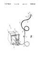
- FIG. 1is a perspective assembly view of a borescope that employs a hooking device according to one embodiment of this invention.
- FIG. 2is a sectional representation of a portion of a turbine jet engine in which the borescope of this invention is employed for inspection purposes.
- FIGS. 3 and 4are perspective views of the distal end of the borescope with the hooking device removed and installed, respectively.
- FIG. 5is a plan view of a cut sheet blank for forming the hooking device of this embodiment.
- FIG. 6is a side elevation of the hooking device of this embodiment.
- FIG. 7is an end view taken at lines 7--7 of FIGS. 6.
- FIG. 8 and 9are perspective views of the distal end of a borescope and a hooking device according to a second embodiment, with the hooking device respectively shown removed and installed on the borescope.
- FIGS. 10 and 11are perspective views of the distal end of a borescope and a hooking device of a third embodiment, with the hooking device respectively shown removed and installed on the borescope.
- FIG. 1shows a video borescope and processor assembly 10 which comprises a video monitor 12 having a screen 14, and an electronic processor 16.
- An associated borescope 18has an elongated flexible insertion tube 20 that can be up to fifty feet (sixteen meters) in length, and which has a viewing head incorporated into its distal tip 22.
- This viewing headcontains an optical lens and a miniature video camera.
- the lattercan be formed of a CCD device or other solid-state imager capable of providing a full-color image of a remote target area, e.g., the inside of a boiler tube heat exchanger or a stator vane of a jet engine or gas turbine.
- An example of a suitable solid-state imageris disclosed in U.S. Pat. No. 4,491,865.
- a hooking device 24in the form of an end cap.
- the device 24hooks over a protuberance or protrusion in a remote area, as described later.
- a steering and control unit 26that can be manipulated by an operator to bend a steering section 32 at the front or distal portion of the insertion tube adjacent the viewing head or tip 22.
- the control unit 26couples the insertion tube 20 to a flexible tubular umbilical 28.
- a borescope interface module 30of the plug-in type, substantially as disclosed in U.S. Pat. No. 4,539,586.
- the module 28fits a mating receptacle in the processor 16.
- the hooking device 24has a sleeve portion 34 that fits snugly onto the distal tip 22 of the insertion tube and at least one wing 36 that projects outward from the distal side of the sleeve portion 34.
- the steering section 32bends in one plane only, that is, up and down in a vertical plane.
- a stripe 38appears on the sheath of the insertion tube 20 and extends axially over the operative length of the insertion tube. This stripe lies in the vertical plane, i.e., the bending plane of the steering section 32 and indicates the "up" steering direction. The stripe provides a visual indication to the operator of the orientation of the insertion tube 20 and steering section 32 when the borescope is inserted into an inaccessible area.
- FIG. 2shows the distal end of the borescope insertion tube 20 after it has penetrated into a jet engine 40 for inspection of same.
- the direction of gas flowis right to left, so that the leading edges of the stator vanes and rotor blades are to the right, and their trailing edges are oriented to the left.
- the engine 40has a first stator row 42 formed of a plurality of spaced stator vanes 44, a rotor 46, on which there are a plurality of spaced rotor blades 48, and a second stator row 50 which has a plurality of spaced stator vanes 52.
- the vanes 44, 52 and the blades 48have rounded leading edges 54 and pointed trailing edges 56.
- the first row stator vanes 44 and the rotor blades 48can be inspected without difficulty.
- it is the leading edges 54 of the stator vanes 52 of the second rowthat are also subject to hidden damage. These vanes 52 require the subject probe for inspection.
- Rotor and stator elements behind the second stator row 50have a low incidence of damage, making routine inspection unnecessary in most cases.
- the borescope insertion tube 20is inserted through a guide tube (not shown) into the engine 40.
- the guide tubepositions the insertion tube to enter between a pair of the first row stator vanes 44.
- the operatormaintains the bending plane of the steering section 32 in the plane tangent to the engine's periphery at the inspection location by observing the stripe 38 on the insertion tube as it is passed into the guide tube. This allows the steering section to conform with the curves in the blades 44 and 48.
- the operatorlatches the wing or wings 36 of the device 24 onto the trailing edge 56 of one of the rotor blades 48.
- the rotor 46is then slowly turned in the direction of the arrow of FIG. 2, and this carries the insertion tube so that the tip 22 passes each of the stator vanes 52 in succession. After these vanes have been inspected, the rotor 46 is turned reversely back to its original position for withdrawal of the insertion tube 20. To unlatch the device 24, the operator relaxes the bending section 32 and rotates the insertion tube 20 approximately ninety degrees. This causes the wing 36 to roll out of engagement with the trailing edge 56 of the blade 48. Then the insertion tube can be easily withdrawn.
- the end cap hooking device 24 of this inventionis extremely simple to employ, both in making the necessary engagement with and in disengaging from the rotor blade trailing edge. Also, because the device 24 employs no moving parts which must be manipulated through a forceps channel or air conduit, the borescope insertion tube can be made without provision for such conduits or channels. Thus, with this invention, the borescope that is employed can be made thinner and more flexible than was possible previously.
- the direction of rotor rotation indicated above for pulling the probe into the engineis the same as the rotation direction for engine operation.
- the inspectioncan be performed either during this forward rotation of the rotor or during withdrawal of the probe when the rotation of the rotor is reversed.
- the hooking device 24is designed to pull off from or break away from the distal tip 22 if a predetermined axial force is exceeded. This permits the borescope to be removed without damage to itself or the engine in case the distal tip becomes jammed.
- end cap or hooking device 24is formed entirely of soft aluminum, a material which becomes entirely consumed at the combustion temperatures of the jet engine, a lost end cap or hooking device can remain in the engine without threat of damage to any of the rotor blades or stator vanes.
- the manner in which the hooking device 24 of this invention fits onto the tip or video head 22 of the borescopeis illustrated generally in FIGS. 3 and 4.
- the tiphas a frustoconic or generally cylindrical distal portion 58 in which is formed a generally a L-shaped cutout 60.
- the cutouthas an axial shoulder 62, a distal circumferential shoulder 64, and a proximal circumferential shoulder 66.
- the hooking cap 24has a sleeve portion 34 and two wing portions 36, which are mirror images of one another, positioned distally on the sleeve portion 34. Aligned between the wing portions 36 and extending axially along the sleeve portion 34 is a longitudinal gap 68. The presence of this gap means that the sleeve portion 34 does not add material thickness on the side of the viewing head 22 that abuts the trailing edge 56 of the rotor blades 48.
- Each of the wing portions 36extends laterally, i.e., radially out to a point or wing tip 70 with a radially flat proximal edge 72 extending out to the tip 70, and a curved or swept back distal or leading edge 74.
- the proximal edge 72can be slanted back somewhat.
- An axial strip 76is formed at the distal end of each wing 36 at the side opposite the tip 70.
- the strip 76is bent inward so that its free end forms a proximal circumferential edge 78 and its side forms an axial edge 80.
- the bent-back tabs 76engage the cutouts 60, with the circumferential edges 78 engaging the cutout circumferential shoulders 66, and with the axial edges 80 engaging cutout axial shoulders 62.
- the tabs 76 and cooperating cutouts 60serve to locate the hooking device 24 accurately on the borescope head, both axially and rotationally. This ensures that the viewing head is properly positioned and oriented to produce an erect, in-focus image of the proper magnification.
- Additional tabs 82project axially from adjacent the wings 36. These tabs engage the distal circumferential edges 64 of the cutouts 60 and lock the hooking device in place.
- the tabs 82establish a predetermined, predictable breakaway force at which the tabs 82 will yield to excess axial tensile force and permit the hooking device to be sacrificed if the same becomes jammed.
- a fingernail edge 84 of the sleeve portion 34 opposite the wing tips 70This fingernail edge allows the user to push the hooking cap 24 onto the head 22 easily.
- a v-shaped cutout 86At the proximal end of the sleeve portion 34 and opposite the gap 68 is a v-shaped cutout 86. This cutout 86 avoids contact of the hooking cap 24 and the adjacent rotor blade 48 and thereby permits the viewing head 22 to be aligned closer to the axial direction in the engine 40 for better viewing of the stator vane leading edges 54. The cutouts also reduce the risk of crowbarring or jamming when the borescope is being withdrawn from the engine after inspection.
- FIG. 5shows a flat blank of aluminum sheet, preferably a soft aluminum such as 6061-0 or another suitable material which is durable but would be entirely consumed in jet engine operation if lost in the engine.
- the two wings 36do not proceed radially out to the hooking point where their tips 70 touch or substantially touch. Rather the wings 36 proceed tangentially from the radius of the sleeve portion 34. This provides for easy release of the cap or hooking member from the blade trailing edge 56 when the probe insertion tube 20 is twisted.
- the axial gap 68serves several purposes.
- the gap 68provides clearance so that the blade trailing edge 56 contacts the viewing head 22 rather than the cap or hooking device 24. This maintains a more axial orientation of the probe for a better view of the stator vanes 52.
- the lack of material in the gap 68reduces any tendency for the probe to lodge between the blades 48 if it is inserted backwards.
- the gap 68permits the sleeve portion 34 to spring by radial flexing of the region diametrically opposite the gap. This spring action, in combination with the low yield point of the aluminum material, helps control the radial force of engagement between the hooking device 24 and viewing head 22.
- gap 68allows the hooking device to be made from an aluminum sheet rather than be machined from an aluminum rod or tube.
- the existence of gap 68allows the notch spaces 73 to be easily provided. These notch spaces 73 provide circumferential clearance for the trailing edge 56. With this circumferential clearance, slight angular misalignment of the hooking device 24 with respect to the trailing edge 56 will not cause the wings 36 to disengage from the trailing edge 56.
- the V-shaped notch 86prevents the sleeve portion 34 from contacting the adjacent rotor blade 48 when the probe is properly inserted and hooked. This notch 86 also helps align the hooking device 24 on the viewing head 22 when the hooking device 24 is installed onto the viewing head 22 by the user. To effect this alignment the user lines up the top 87 of the notch 86 with an axial mark 67 incorporated onto the head 22.
- the rotor 46is returned to the original position. Then the insertion tube is rotated or twisted and the hooking cap will dislodge from the trailing edge 56 of the blade 48. The insertion tube 20 can then simply be withdrawn from the engine and guide tube. A similar insertion, inspection, and withdrawal procedure can be carried out using the remaining diametrically opposite inspection port.
- FIGS. 8 and 9A second embodiment of the hooking cap of this invention is shown in FIGS. 8 and 9.
- the probe viewing head 22is configured as in the first embodiment, with the L-shaped cutouts 60 on the frustoconic distal port 58 of the head 22.
- the basic construction of the associated hooking cap or deviceis similar to that of the previously-described embodiment, and similar parts are illustrated and identified with similar reference numbers, but primed.
- the hooking cap 24' of this embodimentsimilar to that of the first embodiment, has a sleeve portion 34' and a pair of wing portions 36', and two tips 70'.
- a tab 88'is defined by a generally U-shaped cutout 90'. This creates in the tab 88' a circumferential edge that engages the circumferential shoulder 66 of the borescope cutout 60 and an axial edge that engages the axial shoulder 62.
- FIGS. 10 and 11A third embodiment of the hooking cap of this invention is illustrated in FIGS. 10 and 11. Parts that are similar to those of the previous embodiments are illustrated and identified with the same reference numbers, but double-primed.
- the head 22" of the probehas a slightly different configuration, with a circumferential shoulder 96" and an axial shoulder 98". Another shoulder which is the mirror image of the shoulder 98" is obscured.
- the hooking cap 24"has a sleeve portion 34" and a pair of wing portions 36" joined to the distal end of the sleeve portion. There is a U-shaped relief area 100" between the wing portions. A circumferential slot 102" formed in each wing portion extends to the area 100" and defines a tab 104" in the wing portion at the side away from the wing tip 70". The tab 104" has a circumferential shoulder 106" and an axial edge 108" that engages the respective axial shoulder 98".
- the locking axial tab 82is omitted.
- the sleeve portion 34"frictionally engages the cylindrical wall of the head 22", and this frictional engagement defines the required breakaway force. This can be adjusted somewhat by adjusting the spring fit of the sleeve portion 34".
- the probecan be employed either with or without the associated hooking cap or hooking device 24, 24' or 24".
- the cutouts and shoulders on the probe tip or viewing headdo not obstruct its passage into narrow passageways when used without the cap.
Landscapes
- Physics & Mathematics (AREA)
- Astronomy & Astrophysics (AREA)
- General Physics & Mathematics (AREA)
- Optics & Photonics (AREA)
- Endoscopes (AREA)
Abstract
Description
The present invention relates to industrial borescopes, especially flexible borescopes of the type that can be employed to inspect the condition of a gas turbine or jet engine.
Borescopes of this type have elongated flexible probes, which can have either a miniature video camera at the distal tip or a fiber optic imaging system extending the length of the probe. These probes are employed to penetrate into an inaccessible area of a jet engine or other object to view a target area inside it. Flexible borescopes are often employed to inspect vanes of a stator row in a turbine for foreign object damage. An aeronautical jet engine typically has an inspection port that receives a guide tube which extends from outside the engine to a position near the first stator row. The flexible probe is inserted through the guide tube and then is passed through the vanes of the first stator row into the rotor. There, the tip of the flexible probe latches onto a trailing edge of one of the rotor blades, or else is wedged between two adjacent rotor blades. The jet engine maintenance operator can then observe the leading edges of the vanes in the next stator row as the rotor is slowly turned. This procedure typically permits inspection of one half of the stator vanes in the second row. Then, the rotor is reversed one half turn and the probe is removed. Following this, the probe and guide tube are inserted into a second inspection port and the remaining stator vanes in the second row are inspected in a similar fashion. In some engines, only one inspection port is available so that the borescope must be sufficiently long to inspect all the stator vanes in the second row. Inspection by means of a flexible borescope permits the most susceptible parts of the jet engine or gas turbine to be inspected without disassembling the engine.
A flexible probe which employs an inflatable bladder mechanism for lodging the borescope tip between rotor vanes is described in U.S. Pat. No. 3,841,764. Probes of this type require an inflatable bag or bladder, an inflating mechanism, and an air tube which runs the length of the flexible probe beneath its outer sheath.
Another borescope employs a forceps hook to latch onto the trailing edge of the rotor blades, and is described in U.S. Pat. No. 4,847,817. In this arrangement, an aluminum hook is screwed onto an elongated flexible cable that passes through a tool forceps channel within the insertion tube. In arrangements of this type, the hook can become difficult to manipulate as the operator is required to rotate the cable within the forceps channel to orient the hook. At the same time, the operator must also steer the probe and manipulate its insertion tube.
Both of the above-mentioned prior systems require the borescopes to have additional channels within them, either to inflate the bladder, or to carry the hook cable. Consequently, the borescope insertion tube is of a greater diameter and is somewhat more complex and costly than if the additional channels were omitted.
A hooking cap for borescopes has been described in my copending U.S. Pat. application Ser. No. 451,016 filed Dec. 15, 1989, and having a common assignee herewith. In that case, a hooking cap is removably attached onto the distal tip of the borescope insertion tube; the hooking cap has a flange that can be latched onto and removed from a projection such as the trailing edge of one of the blades of the rotor of a jet engine being inspected and/or serviced. In the various embodiments of the hook cap disclosed in this earlier patent application, the hook cap has a tubular sleeve that overfits the tip of the borescope and a flange that projects radially out from a distal end of the sleeve. In one version the hook flange is annular, but in other versions it can be lobate. The engaging side of the flange can be flat, or can be bent back proximally. As there disclosed, the sleeve can have one or more inwardly projecting lips that engage corresponding transverse slots on the insertion tube tip. The lips are constructed to release from the slots if a predetermined axial breakaway force is exceeded. The hook cap is entirely of aluminum or another material that will be consumed in combustion if it is lost from the borescope tip, and so it will not cause foreign object damage to the jet engine or turbine.
These hook caps are cast aluminum or machined aluminum, and can be difficult to produce to tolerance, except at considerable cost. Also, the finite thickness of the sleeve can push the probe's line of sight away from the engine axis, thus rendering some portions of the stator vanes difficult to see clearly. Moreover, because the hook flange protrudes from both sides of the probe tip, the hook can engage the rotor blade backwards or can wedge into the space between blades. This can increase the frequency of hook cap loss, making consumption of the hook caps much higher than it ought to be.
Accordingly, it is an object of this invention to facilitate visual inspection of the vanes in the second stator row of a jet engine or gas turbine with a borescope or similar elongated flexible probe.
It is another object of this invention to provide simple structure which can be easily attached onto a trailing edge of a rotor blade, and then can be removed from the rotor blade without difficulty when desired.
It is yet another object of this invention to provide attachment structure which permits the use of a flexible optical or video borescope without a forceps channel or fluid conduit.
It is still another object of this invention to provide an attachment device for a jet engine inspection probe which can have either two-way or four-way steering.
It is a further object to provide simple and inexpensive structure for a hook cap for an elongated probe which is simple to attach and remove, and which achieves improved viewing characteristics for inspecting the vanes in the second stator row of jet engines or turbines.
In accordance with a significant aspect of this invention, a flexible borescope has an elongated flexible insertion tube for penetrating a passage into an inaccessible area of a device to be visually inspected, such as the turbine mechanism of a jet engine. The probe has an imaging system, which can be e.g. a miniature video camera or a fiber optic system, disposed at the distal tip of the insertion tube for forming an image of a target in the inaccessible area and for conducting the image to a viewing device that is coupled to a proximal end of the insertion tube. The distal tip of the borescope has a generally cylindrical wall in which one or more cutouts are formed, each cutout having an axial shoulder and a circumferential shoulder.
A hooking member is removably attached onto the distal tip of the insertion tube for controllably latching onto a projection in an inaccessible area, such as the trailing edge of a rotor blade. The hooking member includes a circumferential sleeve portion that overfits the insertion tube tip and at least one wing whose tip projects generally radially out from the sleeve portion sufficiently to engage the rotor blade trailing edge or other projection. Each such wing includes a tab that has an axial edge and a circumferential edge to engage the axial and circumferential shoulders of an associated one of the one or more cutouts. This firmly locates the hook member circumferentially and axially on the distal tip of the borescope. This establishes a fixed relation for the hook member circumferentially (to establish an azimuth for bending neck articulation and for the vertical picture axis of the imager) and axially (to position the imager optimally for viewing the stator vanes).
Preferably, the hook members are formed unitarily of sheet aluminum. The sleeve portion is formed with a gap that extends its axial length. Two wings are joined to the distal end of the sleeve portion, and these angle towards each other so that their tips touch or substantially touch at a position on the same side as the gap. The presence of the gap allows the tip of the probe to align closer to the axial direction of the engine so that a better view is obtained of the leading edges of the stator vanes.
The tabs mentioned above can be formed as defined by cutouts on the wings at a position circumferentially away from the tip. Alternatively the tabs can include axial strips at the distal ends of the wings, these strips being bent back against an inside surface of the wing at an edge away from the wing tip. An additional locking tab can project distally from the sleeve adjacent the wing to engage another circumferential shoulder of the cutout and yieldably to lock the hook member onto the probe tip.
The wing of the hooking member can be easily and securely hooked over the trailing edge of the jet engine rotor blade, and will not come off inadvertently. However, when desired to remove the probe from the engine, the hooking member can be dislodged by rotating the insertion tube. This causes the wing tip to roll off the trailing edge of the blade and become dislodged.
The hooking member is unitarily fabricated of aluminum. If the cap is lost in the jet engine, it will become consumed at the engine's characteristic operating temperatures, and thus will not cause any damage to the engine.
The probe is employed by inserting it through the guide tube which has been installed in the engine's or turbine's inspection port, and by hooking the wings over the trailing edge of the rotor blade. Then the rotor is turned slowly for a half rotation, so that the leading edges of the second row of stator vanes come into view. After these stator vanes have been inspected, the rotor is turned back to its original position. The operator them simply twists the insertion tube to dislodge the hooking member by rolling it off from the rotor blade. Then the probe is pulled out of the guide tube and, using a similar procedure, is inserted through the guide tube which has been installed in this second port. The probe is then used to inspect the remaining stator vanes. In some engines only one inspection port is available, so that the rotor is turned a full rotation to inspect the stator vanes.
The above and many other objects, features and advantages of this invention will be more fully understood from the ensuing description of a preferred embodiment, which is to be read in connection with the accompanying Drawing.
FIG. 1 is a perspective assembly view of a borescope that employs a hooking device according to one embodiment of this invention.
FIG. 2 is a sectional representation of a portion of a turbine jet engine in which the borescope of this invention is employed for inspection purposes.
FIGS. 3 and 4 are perspective views of the distal end of the borescope with the hooking device removed and installed, respectively.
FIG. 5 is a plan view of a cut sheet blank for forming the hooking device of this embodiment.
FIG. 6 is a side elevation of the hooking device of this embodiment.
FIG. 7 is an end view taken atlines 7--7 of FIGS. 6.
FIG. 8 and 9 are perspective views of the distal end of a borescope and a hooking device according to a second embodiment, with the hooking device respectively shown removed and installed on the borescope.
FIGS. 10 and 11 are perspective views of the distal end of a borescope and a hooking device of a third embodiment, with the hooking device respectively shown removed and installed on the borescope.
With reference to the Drawing, FIG. 1 shows a video borescope and processor assembly 10 which comprises avideo monitor 12 having ascreen 14, and anelectronic processor 16. An associatedborescope 18 has an elongatedflexible insertion tube 20 that can be up to fifty feet (sixteen meters) in length, and which has a viewing head incorporated into itsdistal tip 22. This viewing head contains an optical lens and a miniature video camera. The latter can be formed of a CCD device or other solid-state imager capable of providing a full-color image of a remote target area, e.g., the inside of a boiler tube heat exchanger or a stator vane of a jet engine or gas turbine. An example of a suitable solid-state imager is disclosed in U.S. Pat. No. 4,491,865.
At thedistal tip 22 of the insertion tube there is a hookingdevice 24 in the form of an end cap. Thedevice 24 hooks over a protuberance or protrusion in a remote area, as described later.
At the back or proximal end of theinsertion tube 20 is a steering andcontrol unit 26 that can be manipulated by an operator to bend asteering section 32 at the front or distal portion of the insertion tube adjacent the viewing head ortip 22. Thecontrol unit 26 couples theinsertion tube 20 to a flexible tubular umbilical 28. At the proximal end of the umbilical 28 is aborescope interface module 30 of the plug-in type, substantially as disclosed in U.S. Pat. No. 4,539,586. In this embodiment, themodule 28 fits a mating receptacle in theprocessor 16.
As also shown generally in FIG. 1, the hookingdevice 24 has asleeve portion 34 that fits snugly onto thedistal tip 22 of the insertion tube and at least onewing 36 that projects outward from the distal side of thesleeve portion 34.
In this embodiment, thesteering section 32 bends in one plane only, that is, up and down in a vertical plane. Astripe 38 appears on the sheath of theinsertion tube 20 and extends axially over the operative length of the insertion tube. This stripe lies in the vertical plane, i.e., the bending plane of thesteering section 32 and indicates the "up" steering direction. The stripe provides a visual indication to the operator of the orientation of theinsertion tube 20 andsteering section 32 when the borescope is inserted into an inaccessible area. This is a significant advantage to the operator in orienting the borescope and threading the same through the stator vanes and rotor blades of a jet turbine so that the hooking device or cap 24 can be easily hooked onto the trailing edge of one of the rotor blades. For a probe with four-way steering, distinctive stripes or markings on the sheath of the insertion tube can indicate the horizontal and vertical steering planes and e.g., the "up" and "right" steering directions.
FIG. 2 shows the distal end of theborescope insertion tube 20 after it has penetrated into ajet engine 40 for inspection of same. In this view, the direction of gas flow is right to left, so that the leading edges of the stator vanes and rotor blades are to the right, and their trailing edges are oriented to the left.
Theengine 40 has afirst stator row 42 formed of a plurality of spacedstator vanes 44, arotor 46, on which there are a plurality of spacedrotor blades 48, and asecond stator row 50 which has a plurality of spacedstator vanes 52. Thevanes blades 48 have rounded leadingedges 54 and pointed trailingedges 56. Generally the firstrow stator vanes 44 and therotor blades 48 can be inspected without difficulty. However, it is theleading edges 54 of thestator vanes 52 of the second row that are also subject to hidden damage. Thesevanes 52 require the subject probe for inspection. Rotor and stator elements behind thesecond stator row 50 have a low incidence of damage, making routine inspection unnecessary in most cases.
To inspect theleading edges 54 of thevanes 52, theborescope insertion tube 20 is inserted through a guide tube (not shown) into theengine 40. The guide tube positions the insertion tube to enter between a pair of the first row stator vanes 44. The operator maintains the bending plane of thesteering section 32 in the plane tangent to the engine's periphery at the inspection location by observing thestripe 38 on the insertion tube as it is passed into the guide tube. This allows the steering section to conform with the curves in theblades control unit 26, the operator latches the wing orwings 36 of thedevice 24 onto the trailingedge 56 of one of therotor blades 48. Therotor 46 is then slowly turned in the direction of the arrow of FIG. 2, and this carries the insertion tube so that thetip 22 passes each of thestator vanes 52 in succession. After these vanes have been inspected, therotor 46 is turned reversely back to its original position for withdrawal of theinsertion tube 20. To unlatch thedevice 24, the operator relaxes thebending section 32 and rotates theinsertion tube 20 approximately ninety degrees. This causes thewing 36 to roll out of engagement with the trailingedge 56 of theblade 48. Then the insertion tube can be easily withdrawn.
With the above-described procedure, half of thetotal rotor vanes 56 are typically inspected. The operation is repeated to inspect the remaining half by inserting the borescope through the guide tube into a radially opposite inspection port on the other side of theengine 40. Then like procedures are followed to inspect the remainingstator vanes 52.
It has been found that the endcap hooking device 24 of this invention is extremely simple to employ, both in making the necessary engagement with and in disengaging from the rotor blade trailing edge. Also, because thedevice 24 employs no moving parts which must be manipulated through a forceps channel or air conduit, the borescope insertion tube can be made without provision for such conduits or channels. Thus, with this invention, the borescope that is employed can be made thinner and more flexible than was possible previously.
The direction of rotor rotation indicated above for pulling the probe into the engine is the same as the rotation direction for engine operation. The inspection can be performed either during this forward rotation of the rotor or during withdrawal of the probe when the rotation of the rotor is reversed.
The hookingdevice 24 is designed to pull off from or break away from thedistal tip 22 if a predetermined axial force is exceeded. This permits the borescope to be removed without damage to itself or the engine in case the distal tip becomes jammed.
Because the end cap or hookingdevice 24 is formed entirely of soft aluminum, a material which becomes entirely consumed at the combustion temperatures of the jet engine, a lost end cap or hooking device can remain in the engine without threat of damage to any of the rotor blades or stator vanes.
The manner in which the hookingdevice 24 of this invention fits onto the tip orvideo head 22 of the borescope is illustrated generally in FIGS. 3 and 4. The tip has a frustoconic or generally cylindricaldistal portion 58 in which is formed a generally a L-shapedcutout 60. The cutout has anaxial shoulder 62, a distalcircumferential shoulder 64, and a proximalcircumferential shoulder 66. There is a second cut-out, not visible in this view, which is opposite thecutout 60 on theportion 58 and is a mirror image thereof.
The hookingcap 24 has asleeve portion 34 and twowing portions 36, which are mirror images of one another, positioned distally on thesleeve portion 34. Aligned between thewing portions 36 and extending axially along thesleeve portion 34 is alongitudinal gap 68. The presence of this gap means that thesleeve portion 34 does not add material thickness on the side of theviewing head 22 that abuts the trailingedge 56 of therotor blades 48.
Each of thewing portions 36 extends laterally, i.e., radially out to a point orwing tip 70 with a radially flatproximal edge 72 extending out to thetip 70, and a curved or swept back distal or leadingedge 74. In other embodiments theproximal edge 72 can be slanted back somewhat.
Anaxial strip 76 is formed at the distal end of eachwing 36 at the side opposite thetip 70. Thestrip 76 is bent inward so that its free end forms a proximalcircumferential edge 78 and its side forms anaxial edge 80. When the hookingmember 24 is installed onto theborescope viewing head 22, the bent-back tabs 76 engage thecutouts 60, with thecircumferential edges 78 engaging the cutout circumferential shoulders 66, and with theaxial edges 80 engaging cutoutaxial shoulders 62. Thetabs 76 and cooperatingcutouts 60 serve to locate the hookingdevice 24 accurately on the borescope head, both axially and rotationally. This ensures that the viewing head is properly positioned and oriented to produce an erect, in-focus image of the proper magnification.
Between thetabs 82 is afingernail edge 84 of thesleeve portion 34 opposite thewing tips 70. This fingernail edge allows the user to push the hookingcap 24 onto thehead 22 easily. At the proximal end of thesleeve portion 34 and opposite thegap 68 is a v-shapedcutout 86. Thiscutout 86 avoids contact of the hookingcap 24 and theadjacent rotor blade 48 and thereby permits theviewing head 22 to be aligned closer to the axial direction in theengine 40 for better viewing of the statorvane leading edges 54. The cutouts also reduce the risk of crowbarring or jamming when the borescope is being withdrawn from the engine after inspection.
The construction of the hooking device orend cap 24 of this embodiment can be seen in FIGS. 5, 6, and 7. FIG. 5 shows a flat blank of aluminum sheet, preferably a soft aluminum such as 6061-0 or another suitable material which is durable but would be entirely consumed in jet engine operation if lost in the engine. As shown in FIGS. 6 and 7, the twowings 36 do not proceed radially out to the hooking point where theirtips 70 touch or substantially touch. Rather thewings 36 proceed tangentially from the radius of thesleeve portion 34. This provides for easy release of the cap or hooking member from theblade trailing edge 56 when theprobe insertion tube 20 is twisted.
Theaxial gap 68 serves several purposes. First, thegap 68 provides clearance so that theblade trailing edge 56 contacts theviewing head 22 rather than the cap or hookingdevice 24. This maintains a more axial orientation of the probe for a better view of the stator vanes 52. Second, the lack of material in thegap 68 reduces any tendency for the probe to lodge between theblades 48 if it is inserted backwards. Third, thegap 68 permits thesleeve portion 34 to spring by radial flexing of the region diametrically opposite the gap. This spring action, in combination with the low yield point of the aluminum material, helps control the radial force of engagement between the hookingdevice 24 andviewing head 22. Fourth, thegap 68 allows the hooking device to be made from an aluminum sheet rather than be machined from an aluminum rod or tube. Fifth, the existence ofgap 68 allows thenotch spaces 73 to be easily provided. Thesenotch spaces 73 provide circumferential clearance for the trailingedge 56. With this circumferential clearance, slight angular misalignment of the hookingdevice 24 with respect to the trailingedge 56 will not cause thewings 36 to disengage from the trailingedge 56.
The V-shapednotch 86 prevents thesleeve portion 34 from contacting theadjacent rotor blade 48 when the probe is properly inserted and hooked. Thisnotch 86 also helps align the hookingdevice 24 on theviewing head 22 when the hookingdevice 24 is installed onto theviewing head 22 by the user. To effect this alignment the user lines up the top 87 of thenotch 86 with anaxial mark 67 incorporated onto thehead 22.
To remove the probe from the engine orturbine 40 following an inspection of the blades, therotor 46 is returned to the original position. Then the insertion tube is rotated or twisted and the hooking cap will dislodge from the trailingedge 56 of theblade 48. Theinsertion tube 20 can then simply be withdrawn from the engine and guide tube. A similar insertion, inspection, and withdrawal procedure can be carried out using the remaining diametrically opposite inspection port.
A second embodiment of the hooking cap of this invention is shown in FIGS. 8 and 9. Here, theprobe viewing head 22 is configured as in the first embodiment, with the L-shapedcutouts 60 on the frustoconicdistal port 58 of thehead 22. The basic construction of the associated hooking cap or device is similar to that of the previously-described embodiment, and similar parts are illustrated and identified with similar reference numbers, but primed.
As illustrated the hooking cap 24' of this embodiment, similar to that of the first embodiment, has a sleeve portion 34' and a pair of wing portions 36', and two tips 70'. A tab 88' is defined by a generally U-shaped cutout 90'. This creates in the tab 88' a circumferential edge that engages thecircumferential shoulder 66 of theborescope cutout 60 and an axial edge that engages theaxial shoulder 62.
A third embodiment of the hooking cap of this invention is illustrated in FIGS. 10 and 11. Parts that are similar to those of the previous embodiments are illustrated and identified with the same reference numbers, but double-primed.
In this embodiment, thehead 22" of the probe has a slightly different configuration, with acircumferential shoulder 96" and anaxial shoulder 98". Another shoulder which is the mirror image of theshoulder 98" is obscured.
The hookingcap 24" has asleeve portion 34" and a pair ofwing portions 36" joined to the distal end of the sleeve portion. There is aU-shaped relief area 100" between the wing portions. Acircumferential slot 102" formed in each wing portion extends to thearea 100" and defines atab 104" in the wing portion at the side away from thewing tip 70". Thetab 104" has acircumferential shoulder 106" and anaxial edge 108" that engages the respectiveaxial shoulder 98".
In this embodiment, the lockingaxial tab 82 is omitted. Thesleeve portion 34" frictionally engages the cylindrical wall of thehead 22", and this frictional engagement defines the required breakaway force. This can be adjusted somewhat by adjusting the spring fit of thesleeve portion 34".
In each case, the probe can be employed either with or without the associated hooking cap or hookingdevice
While the invention has been described in detail with reference to a few selected embodiments, it should be understood that the invention is not limited to those precise embodiments; rather, many modifications and variations would present themselves to those skilled in the art without departing from the scope and spirit of this invention, as defined in the appended claims.
Claims (17)
1. A flexible borescope comprising a flexible elongated insertion tube for permitting a passage into an inaccessible area of a device to be visually inspected, imaging means disposed in a distal tip of said insertion tube for forming an image of a target in an inaccessible area and conducting the image to a viewing device coupled to a proximal end of the insertion tube, the distal tip having a peripheral wall in which a cutout is formed having an axial shoulder and a proximal circumferential shoulder, and a hook member removably attached onto the distal tip of the insertion tube for controllably latching onto a projection in said inaccessible area, the hook member including a sleeve circumferentially over-fitting said tip and at least one wing having a tip projecting to a hook point radially outward from a distal end of said sleeve to hook over said projection each said wing including a tab having an axial edge and a circumferential edge to engage the axial and circumferential shoulders of the associated cutout to firmly locate the hook member circumferentially and axially on the distal tip.
2. The flexible borescope of claim 1 wherein there are two of said cutouts disposed on said borescope tip and said hook member includes two said wings, each having an associated tab to engage a respective one of said cutouts.
3. The flexible borescope of claim 1 wherein said hook member is formed unitarily of a sheet of aluminum.
4. The flexible borescope of claim 1 wherein said sleeve has an axial gap therethrough generally aligned with said at least one wing.
5. The flexible borescope of claim 1 wherein each said tab is formed in its respective wing on a side thereof circumferentially away from its tip.
6. The flexible borescope of claim 5 wherein each said tab is formed by a cutout in said wing on the side away from its tip.
7. The flexible borescope of claim 5 wherein each said tab includes an axial strip at the distal end of said wing and bent back against said side away from the wing tip.
8. The flexible borescope of claim 5 further including a distal circumferential shoulder in said distal tip.
9. The flexible borescope of claim 8 further comprising a locking tab projecting distally from said sleeve adjacent said wing, said locking tab to engage said distal circumferential shoulder in said distal tip.
10. A hooking cap which removably attaches to a generally cylindrical distal tip of an elongated flexible borescope, the hooking cap comprising a generally cylindrical sleeve that circumferentially overfits said borescope distal tip; and at least one wing disposed at a distal end of said sleeve and projecting generally radially to a wing tip that lies radially outward of the tip of borescope a distance sufficient to permit hooking onto a projection, each said wing including a tab formed thereon on a side away from the wing tip, the tab having an axial edge and a circumferential edge to engage axial and proximal circumferential shoulders on the borescope distal tip.
11. The hooking cap of claim 10 wherein there are two of said wings having wing tips that project both to the same side of the borescope tip.
12. The hooking cap of claim 11 wherein said wings angle towards a common point such that the wing tips substantially meet.
13. The hooking cap of claim 11 wherein said sleeve has an axial gap therethrough disposed on the side at which the wing tips project.
14. The hooking cap of claim 10 wherein said sleeve and each said wing are all unitarily formed of aluminum sheet.
15. The hooking cap of claim 10 wherein each said tab is formed by a cutout in the associated wing on the side away from the wing tip.
16. The hooking cap of claim 10 wherein said tab includes an axial strip at a distal edge of one said wing, which strip is bent back against a side of the associated wing away from the wing tip.
17. The hooking cap of claim 10 further comprising a locking tab projecting distally from said sleeve adjacent an associated one of said at least one wing, said locking tab to engage said distal circumferential shoulder in said distal tip.
Priority Applications (1)
| Application Number | Priority Date | Filing Date | Title |
|---|---|---|---|
| US07/609,464US5066122A (en) | 1990-11-05 | 1990-11-05 | Hooking cap for borescope |
Applications Claiming Priority (1)
| Application Number | Priority Date | Filing Date | Title |
|---|---|---|---|
| US07/609,464US5066122A (en) | 1990-11-05 | 1990-11-05 | Hooking cap for borescope |
Publications (1)
| Publication Number | Publication Date |
|---|---|
| US5066122Atrue US5066122A (en) | 1991-11-19 |
Family
ID=24440911
Family Applications (1)
| Application Number | Title | Priority Date | Filing Date |
|---|---|---|---|
| US07/609,464Expired - LifetimeUS5066122A (en) | 1990-11-05 | 1990-11-05 | Hooking cap for borescope |
Country Status (1)
| Country | Link |
|---|---|
| US (1) | US5066122A (en) |
Cited By (36)
| Publication number | Priority date | Publication date | Assignee | Title |
|---|---|---|---|---|
| US5500918A (en)* | 1994-12-28 | 1996-03-19 | Welch Allyn, Inc. | Bifurcated fiber bundle in single head light cable for use with multi-source light box |
| US5717806A (en)* | 1994-12-28 | 1998-02-10 | Welch Allyn, Inc. | Bifurcated randomized fiber bundle light cable for directing light from multiple light sources to single light output |
| US5836762A (en)* | 1993-10-08 | 1998-11-17 | Dentsply International Inc. | Portable dental camera system and method |
| WO2000004329A1 (en)* | 1998-07-14 | 2000-01-27 | Fosbel International Limited | Camera insertion into a furnace |
| US20020018798A1 (en)* | 2000-06-21 | 2002-02-14 | Merck Patent Gesellschaft Mit Beschrankter Haftung | Coating for metallic implant materials |
| US20040183900A1 (en)* | 2003-03-20 | 2004-09-23 | Everest Vit | Method and system for automatically detecting defects in remote video inspection applications |
| US20060038988A1 (en)* | 2004-08-20 | 2006-02-23 | General Electric Company | Borescope assembly for detecting a condition of a rotating part |
| US20060072903A1 (en)* | 2001-02-22 | 2006-04-06 | Everest Vit, Inc. | Method and system for storing calibration data within image files |
| US20060088793A1 (en)* | 2004-10-22 | 2006-04-27 | Siemens Westinghouse Power Corporation | Optical viewing system for monitoring a wide angle area of interest exposed to high temperature |
| US20070070340A1 (en)* | 2005-06-22 | 2007-03-29 | Karpen Thomas W | Remote video inspection system integrating audio communication functionality |
| US20070091183A1 (en)* | 2005-10-21 | 2007-04-26 | Ge Inspection Technologies, Lp | Method and apparatus for adapting the operation of a remote viewing device to correct optical misalignment |
| US20070187574A1 (en)* | 2006-02-13 | 2007-08-16 | Ge Inspection Technologies, Lp | Electronic imaging device with photosensor arrays |
| US20070225931A1 (en)* | 2006-03-27 | 2007-09-27 | Ge Inspection Technologies, Lp | Inspection apparatus for inspecting articles |
| US20080116093A1 (en)* | 2003-01-29 | 2008-05-22 | Ge Inspection Technologies Lp | Apparatus for storing an insertion tube |
| US20080151046A1 (en)* | 2006-12-22 | 2008-06-26 | Ge Inspection Technologies, Lp | Heat protection systems and methods for remote viewing devices |
| US7422559B2 (en) | 2004-06-16 | 2008-09-09 | Ge Inspection Technologies, Lp | Borescope comprising fluid supply system |
| US20090109283A1 (en)* | 2007-10-26 | 2009-04-30 | Joshua Lynn Scott | Integrated storage for industrial inspection handset |
| US20090109045A1 (en)* | 2007-10-26 | 2009-04-30 | Delmonico James J | Battery and power management for industrial inspection handset |
| US20090109429A1 (en)* | 2007-10-26 | 2009-04-30 | Joshua Lynn Scott | Inspection apparatus having heat sink assembly |
| US7564626B2 (en) | 2002-01-25 | 2009-07-21 | Ge Inspection Technologies Lp | Stereo-measurement borescope with 3-D viewing |
| EP2119875A2 (en) | 2008-05-12 | 2009-11-18 | Rolls-Royce plc | An inspection arrangement |
| US7819798B2 (en) | 2005-06-24 | 2010-10-26 | Ge Inspection Technologies, Lp | Insertion tube storage carousel |
| US20100314443A1 (en)* | 2009-06-12 | 2010-12-16 | Hand Held Products, Inc. | Portable Data Terminal |
| US20110211940A1 (en)* | 2010-02-26 | 2011-09-01 | General Electric Company | System and method for inspection of stator vanes |
| US8213676B2 (en) | 2006-12-20 | 2012-07-03 | Ge Inspection Technologies Lp | Inspection apparatus method and apparatus comprising motion responsive control |
| US8310604B2 (en) | 2007-10-26 | 2012-11-13 | GE Sensing & Inspection Technologies, LP | Visual inspection apparatus having light source bank |
| US8514278B2 (en) | 2006-12-29 | 2013-08-20 | Ge Inspection Technologies Lp | Inspection apparatus having illumination assembly |
| US8625434B2 (en) | 2006-12-29 | 2014-01-07 | Ge Inspection Technologies Lp | IP based voice communication enabled inspection system |
| US8810636B2 (en) | 2006-12-20 | 2014-08-19 | Ge Inspection Technologies, Lp | Inspection apparatus method and apparatus comprising selective frame output |
| US10291850B2 (en) | 2006-12-20 | 2019-05-14 | General Electric Company | Inspection apparatus method and apparatus comprising selective frame output |
| JP2020537079A (en)* | 2017-10-16 | 2020-12-17 | ルフトハンザ・テッヒニク・アクチェンゲゼルシャフトLufthansa Technik Ag | Equipment and methods for borescope inspection of jet engines |
| US10942964B2 (en) | 2009-02-02 | 2021-03-09 | Hand Held Products, Inc. | Apparatus and method of embedding meta-data in a captured image |
| US11103964B2 (en)* | 2018-12-06 | 2021-08-31 | General Electric Company | Service apparatus for use with rotary machines |
| US11360297B2 (en) | 2020-02-20 | 2022-06-14 | Delta Air Lines, Inc. | Marker attachment device for a borescope |
| US12186848B1 (en) | 2024-01-26 | 2025-01-07 | General Electric Company | Method and apparatus for servicing engines |
| US12195202B1 (en) | 2024-01-26 | 2025-01-14 | General Electric Company | System and method for servicing aircraft engines |
Citations (1)
| Publication number | Priority date | Publication date | Assignee | Title |
|---|---|---|---|---|
| US4298312A (en)* | 1979-07-24 | 1981-11-03 | Purex Corporation | Damaged vane locating method and apparatus |
- 1990
- 1990-11-05USUS07/609,464patent/US5066122A/ennot_activeExpired - Lifetime
Patent Citations (1)
| Publication number | Priority date | Publication date | Assignee | Title |
|---|---|---|---|---|
| US4298312A (en)* | 1979-07-24 | 1981-11-03 | Purex Corporation | Damaged vane locating method and apparatus |
Cited By (53)
| Publication number | Priority date | Publication date | Assignee | Title |
|---|---|---|---|---|
| US5836762A (en)* | 1993-10-08 | 1998-11-17 | Dentsply International Inc. | Portable dental camera system and method |
| US5717806A (en)* | 1994-12-28 | 1998-02-10 | Welch Allyn, Inc. | Bifurcated randomized fiber bundle light cable for directing light from multiple light sources to single light output |
| US5500918A (en)* | 1994-12-28 | 1996-03-19 | Welch Allyn, Inc. | Bifurcated fiber bundle in single head light cable for use with multi-source light box |
| WO2000004329A1 (en)* | 1998-07-14 | 2000-01-27 | Fosbel International Limited | Camera insertion into a furnace |
| US6229563B1 (en) | 1998-07-14 | 2001-05-08 | Fosbel International Limited | Camera insertion into a furnace |
| US20020018798A1 (en)* | 2000-06-21 | 2002-02-14 | Merck Patent Gesellschaft Mit Beschrankter Haftung | Coating for metallic implant materials |
| US20060072903A1 (en)* | 2001-02-22 | 2006-04-06 | Everest Vit, Inc. | Method and system for storing calibration data within image files |
| US7564626B2 (en) | 2002-01-25 | 2009-07-21 | Ge Inspection Technologies Lp | Stereo-measurement borescope with 3-D viewing |
| US20080116093A1 (en)* | 2003-01-29 | 2008-05-22 | Ge Inspection Technologies Lp | Apparatus for storing an insertion tube |
| US20040183900A1 (en)* | 2003-03-20 | 2004-09-23 | Everest Vit | Method and system for automatically detecting defects in remote video inspection applications |
| US7422559B2 (en) | 2004-06-16 | 2008-09-09 | Ge Inspection Technologies, Lp | Borescope comprising fluid supply system |
| US20060038988A1 (en)* | 2004-08-20 | 2006-02-23 | General Electric Company | Borescope assembly for detecting a condition of a rotating part |
| US20060088793A1 (en)* | 2004-10-22 | 2006-04-27 | Siemens Westinghouse Power Corporation | Optical viewing system for monitoring a wide angle area of interest exposed to high temperature |
| US20070070340A1 (en)* | 2005-06-22 | 2007-03-29 | Karpen Thomas W | Remote video inspection system integrating audio communication functionality |
| US7956888B2 (en) | 2005-06-22 | 2011-06-07 | Ge Inspection Technologies, Lp | Remote video inspection system integrating audio communication functionality |
| US7819798B2 (en) | 2005-06-24 | 2010-10-26 | Ge Inspection Technologies, Lp | Insertion tube storage carousel |
| US20070091183A1 (en)* | 2005-10-21 | 2007-04-26 | Ge Inspection Technologies, Lp | Method and apparatus for adapting the operation of a remote viewing device to correct optical misalignment |
| US7679041B2 (en) | 2006-02-13 | 2010-03-16 | Ge Inspection Technologies, Lp | Electronic imaging device with photosensor arrays |
| US20070187574A1 (en)* | 2006-02-13 | 2007-08-16 | Ge Inspection Technologies, Lp | Electronic imaging device with photosensor arrays |
| US20070225931A1 (en)* | 2006-03-27 | 2007-09-27 | Ge Inspection Technologies, Lp | Inspection apparatus for inspecting articles |
| US8310533B2 (en) | 2006-03-27 | 2012-11-13 | GE Sensing & Inspection Technologies, LP | Inspection apparatus for inspecting articles |
| US8368749B2 (en) | 2006-03-27 | 2013-02-05 | Ge Inspection Technologies Lp | Article inspection apparatus |
| US9621808B2 (en) | 2006-12-20 | 2017-04-11 | General Electric Company | Inspection apparatus method and apparatus comprising selective frame output |
| US8810636B2 (en) | 2006-12-20 | 2014-08-19 | Ge Inspection Technologies, Lp | Inspection apparatus method and apparatus comprising selective frame output |
| US10291850B2 (en) | 2006-12-20 | 2019-05-14 | General Electric Company | Inspection apparatus method and apparatus comprising selective frame output |
| US8213676B2 (en) | 2006-12-20 | 2012-07-03 | Ge Inspection Technologies Lp | Inspection apparatus method and apparatus comprising motion responsive control |
| US20080151046A1 (en)* | 2006-12-22 | 2008-06-26 | Ge Inspection Technologies, Lp | Heat protection systems and methods for remote viewing devices |
| US8118733B2 (en) | 2006-12-22 | 2012-02-21 | Ge Inspection Technologies, Lp | Heat protection systems and methods for remote viewing devices |
| US8625434B2 (en) | 2006-12-29 | 2014-01-07 | Ge Inspection Technologies Lp | IP based voice communication enabled inspection system |
| US8514278B2 (en) | 2006-12-29 | 2013-08-20 | Ge Inspection Technologies Lp | Inspection apparatus having illumination assembly |
| US7902990B2 (en) | 2007-10-26 | 2011-03-08 | Ge Inspection Technologies, Lp | Battery and power management for industrial inspection handset |
| US20090109045A1 (en)* | 2007-10-26 | 2009-04-30 | Delmonico James J | Battery and power management for industrial inspection handset |
| US8253782B2 (en) | 2007-10-26 | 2012-08-28 | Ge Inspection Technologies, Lp | Integrated storage for industrial inspection handset |
| US8310604B2 (en) | 2007-10-26 | 2012-11-13 | GE Sensing & Inspection Technologies, LP | Visual inspection apparatus having light source bank |
| US20090109283A1 (en)* | 2007-10-26 | 2009-04-30 | Joshua Lynn Scott | Integrated storage for industrial inspection handset |
| US8767060B2 (en) | 2007-10-26 | 2014-07-01 | Ge Inspection Technologies, Lp | Inspection apparatus having heat sink assembly |
| US20090109429A1 (en)* | 2007-10-26 | 2009-04-30 | Joshua Lynn Scott | Inspection apparatus having heat sink assembly |
| EP2119875A3 (en)* | 2008-05-12 | 2013-09-11 | Rolls-Royce plc | An inspection arrangement |
| EP2119875A2 (en) | 2008-05-12 | 2009-11-18 | Rolls-Royce plc | An inspection arrangement |
| US10942964B2 (en) | 2009-02-02 | 2021-03-09 | Hand Held Products, Inc. | Apparatus and method of embedding meta-data in a captured image |
| US11042793B2 (en) | 2009-06-12 | 2021-06-22 | Hand Held Products, Inc. | Portable data terminal |
| US9519814B2 (en) | 2009-06-12 | 2016-12-13 | Hand Held Products, Inc. | Portable data terminal |
| US9959495B2 (en) | 2009-06-12 | 2018-05-01 | Hand Held Products, Inc. | Portable data terminal |
| US20100314443A1 (en)* | 2009-06-12 | 2010-12-16 | Hand Held Products, Inc. | Portable Data Terminal |
| US8602722B2 (en)* | 2010-02-26 | 2013-12-10 | General Electric Company | System and method for inspection of stator vanes |
| US20110211940A1 (en)* | 2010-02-26 | 2011-09-01 | General Electric Company | System and method for inspection of stator vanes |
| JP2020537079A (en)* | 2017-10-16 | 2020-12-17 | ルフトハンザ・テッヒニク・アクチェンゲゼルシャフトLufthansa Technik Ag | Equipment and methods for borescope inspection of jet engines |
| US11662319B2 (en) | 2017-10-16 | 2023-05-30 | Lufthansa Technik Ag | Device and method for borescope inspection of jet engines |
| US11103964B2 (en)* | 2018-12-06 | 2021-08-31 | General Electric Company | Service apparatus for use with rotary machines |
| US11360297B2 (en) | 2020-02-20 | 2022-06-14 | Delta Air Lines, Inc. | Marker attachment device for a borescope |
| US12186848B1 (en) | 2024-01-26 | 2025-01-07 | General Electric Company | Method and apparatus for servicing engines |
| US12195202B1 (en) | 2024-01-26 | 2025-01-14 | General Electric Company | System and method for servicing aircraft engines |
| EP4628702A1 (en)* | 2024-01-26 | 2025-10-08 | General Electric Company | System and method for servicing aircraft engines |
Similar Documents
| Publication | Publication Date | Title |
|---|---|---|
| US5066122A (en) | Hooking cap for borescope | |
| US5052803A (en) | Mushroom hook cap for borescope | |
| US4298312A (en) | Damaged vane locating method and apparatus | |
| US5253638A (en) | Right-angle detachable variable-position reflector assembly | |
| US8400501B2 (en) | Inspection arrangement | |
| US4727859A (en) | Right angle detachable prism assembly for borescope | |
| JP7189947B2 (en) | Apparatus for jet engine borescope inspection and method for inspecting jet engine turbine blades | |
| CN107085294B (en) | Optical device and inspection tube for inspecting turbine engine components | |
| JPH01500620A (en) | Engine inspection equipment | |
| US6494826B1 (en) | Coupling for a mechanical a light-guiding and an image-guiding connection of an endoscope to a camera module | |
| US9681107B2 (en) | Flexible tether position tracking camera inspection system for visual inspection of off line industrial gas turbines and other power generation machinery | |
| US5280781A (en) | Guide device for endoscope | |
| CA1126053A (en) | Air purging unit for an optical pyrometer of a gas turbine engine | |
| US4011017A (en) | Borescope support apparatus | |
| CN107203036A (en) | Optical imaging system for gas-turbine unit | |
| US10627615B2 (en) | Endoscope distal end portion, endoscope, and optical adaptor | |
| CA2315727A1 (en) | System and method for in vivo delivery of autonomous capsule | |
| US5335061A (en) | Endoscope holding apparatus for inspecting the interiors of a reciprocating engine and rotary engine having ignition plug holes, endoscope apparatus including the endoscope holding apparatus and inspecting method | |
| US20220268170A1 (en) | Multi-tube servicing tool and method of servicing gas turbine engine components | |
| GB2036363A (en) | Inspecting Stator Vanes | |
| JP3383707B2 (en) | Borescope | |
| US6333812B1 (en) | Borescope | |
| US20050215860A1 (en) | Tip structure for variable direction of view endoscope | |
| JP3140542B2 (en) | Industrial endoscope for foreign substance collection | |
| EP3255398A1 (en) | System, method and apparatus for adjusting a flame scanner |
Legal Events
| Date | Code | Title | Description |
|---|---|---|---|
| AS | Assignment | Owner name:WELCH ALLYN, INC., 99 JORDAN ROAD, SKANEATELES FAL Free format text:ASSIGNMENT OF ASSIGNORS INTEREST.;ASSIGNOR:KRAUTER, ALLAN I.;REEL/FRAME:005514/0034 Effective date:19901003 | |
| STCF | Information on status: patent grant | Free format text:PATENTED CASE | |
| FEPP | Fee payment procedure | Free format text:PAYOR NUMBER ASSIGNED (ORIGINAL EVENT CODE: ASPN); ENTITY STATUS OF PATENT OWNER: LARGE ENTITY | |
| FPAY | Fee payment | Year of fee payment:4 | |
| FPAY | Fee payment | Year of fee payment:8 | |
| AS | Assignment | Owner name:EVEREST VISUAL INSPECTION TECHNOLOGIES, INC., NEW Free format text:ASSIGNMENT OF ASSIGNORS INTEREST;ASSIGNOR:WELCH ALLYN, INC.;REEL/FRAME:010247/0269 Effective date:19990908 | |
| FPAY | Fee payment | Year of fee payment:12 | |
| AS | Assignment | Owner name:GE INSPECTION TECHNOLOGIES, LP, PENNSYLVANIA Free format text:ASSIGNMENT OF ASSIGNORS INTEREST;ASSIGNOR:EVEREST VIT, INC.;REEL/FRAME:018047/0642 Effective date:20060331 |