US5065959A - Vibration damping aircraft engine attachment - Google Patents
Vibration damping aircraft engine attachmentDownload PDFInfo
- Publication number
- US5065959A US5065959AUS07/439,318US43931889AUS5065959AUS 5065959 AUS5065959 AUS 5065959AUS 43931889 AUS43931889 AUS 43931889AUS 5065959 AUS5065959 AUS 5065959A
- Authority
- US
- United States
- Prior art keywords
- engine
- airframe
- engines
- vibration
- dampers
- Prior art date
- Legal status (The legal status is an assumption and is not a legal conclusion. Google has not performed a legal analysis and makes no representation as to the accuracy of the status listed.)
- Expired - Lifetime
Links
Images


Classifications
- B—PERFORMING OPERATIONS; TRANSPORTING
- B64—AIRCRAFT; AVIATION; COSMONAUTICS
- B64D—EQUIPMENT FOR FITTING IN OR TO AIRCRAFT; FLIGHT SUITS; PARACHUTES; ARRANGEMENT OR MOUNTING OF POWER PLANTS OR PROPULSION TRANSMISSIONS IN AIRCRAFT
- B64D27/00—Arrangement or mounting of power plants in aircraft; Aircraft characterised by the type or position of power plants
- B64D27/02—Aircraft characterised by the type or position of power plants
- B64D27/10—Aircraft characterised by the type or position of power plants of gas-turbine type
- B64D27/14—Aircraft characterised by the type or position of power plants of gas-turbine type within, or attached to, fuselages
- B—PERFORMING OPERATIONS; TRANSPORTING
- B64—AIRCRAFT; AVIATION; COSMONAUTICS
- B64D—EQUIPMENT FOR FITTING IN OR TO AIRCRAFT; FLIGHT SUITS; PARACHUTES; ARRANGEMENT OR MOUNTING OF POWER PLANTS OR PROPULSION TRANSMISSIONS IN AIRCRAFT
- B64D27/00—Arrangement or mounting of power plants in aircraft; Aircraft characterised by the type or position of power plants
- B64D27/02—Aircraft characterised by the type or position of power plants
- B64D27/16—Aircraft characterised by the type or position of power plants of jet type
- B64D27/18—Aircraft characterised by the type or position of power plants of jet type within, or attached to, wings
- B—PERFORMING OPERATIONS; TRANSPORTING
- B64—AIRCRAFT; AVIATION; COSMONAUTICS
- B64D—EQUIPMENT FOR FITTING IN OR TO AIRCRAFT; FLIGHT SUITS; PARACHUTES; ARRANGEMENT OR MOUNTING OF POWER PLANTS OR PROPULSION TRANSMISSIONS IN AIRCRAFT
- B64D27/00—Arrangement or mounting of power plants in aircraft; Aircraft characterised by the type or position of power plants
- B64D27/40—Arrangements for mounting power plants in aircraft
- B64D27/402—Arrangements for mounting power plants in aircraft comprising box like supporting frames, e.g. pylons or arrangements for embracing the power plant
- B—PERFORMING OPERATIONS; TRANSPORTING
- B64—AIRCRAFT; AVIATION; COSMONAUTICS
- B64D—EQUIPMENT FOR FITTING IN OR TO AIRCRAFT; FLIGHT SUITS; PARACHUTES; ARRANGEMENT OR MOUNTING OF POWER PLANTS OR PROPULSION TRANSMISSIONS IN AIRCRAFT
- B64D27/00—Arrangement or mounting of power plants in aircraft; Aircraft characterised by the type or position of power plants
- B64D27/40—Arrangements for mounting power plants in aircraft
- B64D27/406—Suspension arrangements specially adapted for supporting thrust loads, e.g. thrust links
- B—PERFORMING OPERATIONS; TRANSPORTING
- B64—AIRCRAFT; AVIATION; COSMONAUTICS
- B64D—EQUIPMENT FOR FITTING IN OR TO AIRCRAFT; FLIGHT SUITS; PARACHUTES; ARRANGEMENT OR MOUNTING OF POWER PLANTS OR PROPULSION TRANSMISSIONS IN AIRCRAFT
- B64D27/00—Arrangement or mounting of power plants in aircraft; Aircraft characterised by the type or position of power plants
- B64D2027/005—Aircraft with an unducted turbofan comprising contra-rotating rotors, e.g. contra-rotating open rotors [CROR]
- Y—GENERAL TAGGING OF NEW TECHNOLOGICAL DEVELOPMENTS; GENERAL TAGGING OF CROSS-SECTIONAL TECHNOLOGIES SPANNING OVER SEVERAL SECTIONS OF THE IPC; TECHNICAL SUBJECTS COVERED BY FORMER USPC CROSS-REFERENCE ART COLLECTIONS [XRACs] AND DIGESTS
- Y02—TECHNOLOGIES OR APPLICATIONS FOR MITIGATION OR ADAPTATION AGAINST CLIMATE CHANGE
- Y02T—CLIMATE CHANGE MITIGATION TECHNOLOGIES RELATED TO TRANSPORTATION
- Y02T50/00—Aeronautics or air transport
- Y02T50/60—Efficient propulsion technologies, e.g. for aircraft
Definitions
- This inventionrelates to a novel damped strut for attaching an engine to an aircraft. More particularly, the invention relates to a specially adapted engine mount wherein damping elements are located at the strut-airframe interface.
- UDFunducted fan
- Certain modern unducted fan (UDF) jet engineshave two sets of uncowled counter-rotating propeller blades mounted aft of the combustion chambers and turbines. These blades are large with wide chords and thin cross sections. Accordingly, they present a large target area and could be damaged by impact from solid objects. Modern cowled fan jets with very large cross-sections also present large targets for fan blade damage.
- Rotating damaged blades at high speedscauses unbalanced forces in the engine which are transmitted to the airframe through the engine attachment structure.
- the intensity of the unbalancedepends on the extent of the damage to the blades.
- the flight deck crew or automatic systemsordinarily shut down a damaged engine to reduce the magnitude and duration of such unbalance vibration.
- the high dynamic unbalance loadsmight cause damage to the airframe, engine installation or aircraft control elements and impair the ability of the fight crew to perform critical tasks such as reading flight instruments.
- our inventionprovides a novel means for attaching engines, particularly UDF, helicopter or other large diameter fan engines, to an aircraft which means effectively reduce the adverse effect of vibration and large engine unbalances on the entire structure.
- meanscomprising one or more attachment struts or pylons are provided which extend between an engine and the airframe of an aircraft.
- a plurality of spaced-apart damping elementsare provided between the attachment strut(s) and the airframe, i.e., the fuselage or the wing.
- the damped attachment between the strut and airframemay be branched to optimize load carrying by the airframe, to provide fail safety, and to tune the response of the airframe to the engines under ordinary operating conditions.
- the incorporation of dampers between engine attachment struts and the airframe in accordance with this inventionis particularly adapted to damp vibrations in all directions and reduce the dynamic response of the airframe. It is effective in damping severe vibration due to large engine unbalances, as well as normal operating vibration.
- FIG. 1is a top plan view of a twin engine aircraft with two aft mounted unducted fan engines.
- FIG. 2is a schematic representation of an engine mount strut in accordance with the invention showing two branched end attachment spars which attach to fuselage frames, and a strut closure rib which attaches to the fuselage skin by means of damping elements.
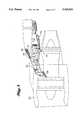
- FIG. 3shows a side sectional view of a wing mounted fan jet engine featuring dampers at strut box-wing attachment points.
- FIG. 4is a perspective schematic view of an engine attachment like that of FIG. 3.
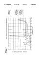
- FIGS. 5 and 6are plots of calculated vertical and lateral accelerations, respectively, experienced within the cockpit of a twin UDF engine aircraft after loss of propeller blades.
- FIGS. 7 and 8are plots of calculated vertical and lateral accelerations, respectively, experienced within the aft cabin of a twin UDF engine aircraft after loss of propeller blades.
- FIG. 1illustrates a top plan view of a tail section 2 of an airplane with an unducted fan engine 4 mounted on either side of the fuselage 6.
- Engines 4 and their mountsare substantially the same or mirror images of one another and the details will be shown and numbered accordingly.
- Each enginehas a first set of rapidly rotating propeller blades 8 and a second similar set 10 rotating in the opposite direction. These are the blades which, if damaged, can cause extreme vibration in the aircraft due to rotational unbalance.
- Forward attachment spar 12, mid attachment spar 14 and rear attachment spar 16, outboard closure rib 18, inboard closure rib 20 and upper and lower skin panels 21are schematically shown and together form the attachment strut 22.
- dampersare included in the attachment between an engine and the outboard end of the strut mount.
- dampersare provided between a fuselage 6 or wing (not shown in FIG. 1) and the inboard end of an attachment strut 22.
- the conventional dampersmay also be included.
- Strut 22may be concealed inside covering airfoil 24.
- FIG. 2is a more detailed schematic representation of an engine mount in accordance with FIG. 1 incorporating a preferred embodiment of a damped strut-airplane engine attachment of this invention.
- the engine and details of its attachment to strut 22are not shown.
- the attachment between the engine and strutmay include dampers of the type shown in U.S. Pat. No. 4,044,973 also assigned to the Boeing Company.
- Inboard closure rib 20connects forward branched spar 12, unbranched mid spar 14 and aft branched spar 16.
- Closure rib 20has thrust damping element 26 attaching it to fuselage skin 28. While one shock absorbing type damping element 26 is shown, more than one damping attachment may be made between the inboard closure rib and the airframe.
- Forward spar 12has an upper branch 32 and a lower branch 34 which are each attached to fuselage frame member 36 under fuselage skin 28 with viscous damping elements 38 and 40 elastomeric dampers 39 and 41, respectively, which react laterally and vertically directed loads.
- rear spar 16has upper and lower branches 42 and 44 which are attached to fuselage frame member 46 under fuselage skin 28 with viscous damping elements 48 and 50 elastomeric dampers 49 and 51.
- the branched ends of forward spar 12 and rear spar 16function together to react the rolling moment. Since each two pronged branched spars is by itself capable of transmitting the lateral and vertical forces and the rolling moment, the combination of any two such branched spars, along with the thrust damping element(s), is capable of transmitting and damping six force-moment components from the strut into the airplane structure. Attachment struts are designed to carry static engine loads, provide fail safety and handle engine vibration. The number of branches and length of mounting spars and struts can be varied in accordance with our invention to best suit a specific damped strut-airframe attachment installation.
- damping elementsbe located at or as close to the source of vibration, i.e., the engine, as possible. Accordingly, it was believed that locating damping elements on the airplane side of an attachment strut would not be an effective means of damping vibrations caused by an engine. Furthermore, it was thought that placing damping elements at or near the inboard end of such a strut would not be effective because vibration from the engine at the outboard end would be amplified through the strut. We have found instead that the subject engine attachment, damped at the airplane-engine strut attachment, effectively damps engine vibration, even extreme vibration created by engine unbalance.
- damping elements and devices used in aircraftthere are many well known damping elements and devices used in aircraft. Each such damping element has certain stiffness and damping characteristics suitable for a specific application.
- the damping elementscan be elastomeric dampers made of synthetic or natural rubber, for example. They may also be viscous dampers, hydraulic dampers, metal mesh resilient dampers, pneumatic dampers, combination damper elements such as hydraulic and pneumatic shock absorbers, or any combination of these or other equivalent damping means.
- Conventional aircraft damper mountscomprise a metal housing containing stiff rubber pads or resilient metal screens sized and shaped to deform under pressure and return to their original shapes and positions when the pressure is relieved. These damping elements may be integrated into an active vibration control system.
- our inventionis also particularly well adapted to active suspension of engines by selective control vibration damping elements.
- the amount of vibration at a desired location or locationswould be measured by conventional means, the information would be processed by a computer, and the damping member would be controlled to optimally damp the measured vibration.
- the response of hydraulic dampers such as 38, 40, 48 and 50 of FIG. 2could be stiffened or relaxed by control of hydraulic fluid pressure therein in response to measured vibration.
- FIGS. 3 and 4show a mount in accordance with our invention which is damped between the attachment strut and wing of an airplane.
- FIG. 3shows a schematic sectional side view of a fan jet engine 52 mounted to wing 54 of an aircraft through torque or strut box 56.
- Strut box 56is attached to engine 52 by forward engine mount 58 and aft engine mount 60.
- strut box 56 inside fairing 62is secured to the wing by a number of damped attachment elements.
- Upper link 64is attached to strut 56 at hinge 66.
- the other endis attached to the wing box by elastomeric damper 68.
- Axial damper 70acts in parallel with damper 68.
- diagonal brace 72is attached to strut 56 at hinge 74.
- the other endis attached to the wing by elastomeric damper 76.
- Axial damper 78acts in parallel with damper 76.
- Side links 82 and 83angle from mid attachment fitting 80 to elastomeric dampers 84 and 85.
- Axial dampers 86 and 87act in parallel with elastomeric dampers 84 and 85.
- Mid spar fittings 88 and 90attach strut 56 to the wing by means of elastomeric dampers 94 and 96.
- Fuse pinsmay be located in the appropriate damping elements, if desired.
- Spacing between the mid spar attachments 88 and 90 side elastomeric dampers 84 and 85provides vibration damping and strength characteristics like the branched ends of the fuselage mounted engine attachment described above.
- the damped upper link and diagonal brace dampers 68 and 76are spaced apart vertically and the midspar fittings 88 and 90 are spaced apart laterally.
- a finite element analysis model for engine unbalance vibrationwas run on a Boeing ATLAS computer program to determine damping characteristics of the branched strut mounting arrangements shown in FIGS. 1 and 2 for a Boeing 7J7 Model 789-177E aircraft. Weights and centers of gravity were assigned for the blades of a prototype General Electric UDF engine and the analysis assumed engine unbalance created by two blades in each set of counter rotating blades missing. Structural damping coefficients for the engines, the aluminum structure of the aircraft and the mounting dampers were assigned based on history with similar aircraft.
- FIGS. 5 and 6are normalized plots of the finite element analysis results in the cockpit for vertical and lateral accelerations, respectively. The results shown are for steady state rotating frequencies between 1 and 21.5 Herz.
- the baselineis the calculated accelerations of a conventional strut and engine mounts with dampers located between the strut and the engine.
- Calculated results for a branched attachment (T-strut) having elastomeric dampersshow a reduction in the cockpit and cabin accelerations both vertically and laterally. Including viscous dampers in addition to the elastomeric dampers further improves damping characteristics of the T-struts.
- FIGS. 7 and 8report like results for the vertical and lateral accelerations experienced in the passenger cabin.
- the dampersare located away from the hot engine and the cooler location permits use of a wide variety of damper designs and materials.
- the dampers at the branched ends of the strutsare located away from the engine cowling; hence there is more space available and they are easy to inspect and service.
- Damperscan be arranged such that they are not in a direct structural load path but parallel to it.
- the number and length of spar branches from the center planes of an attachment strutcan be designed to optimize vibration damping. Vibration isolation brought about by the subject damped branched strut mounting arrangement will reduce vibration and noise in the cockpit and cabin.
Landscapes
- Engineering & Computer Science (AREA)
- Aviation & Aerospace Engineering (AREA)
- Vibration Prevention Devices (AREA)
- Structures Of Non-Positive Displacement Pumps (AREA)
Abstract
Description
This invention relates to a novel damped strut for attaching an engine to an aircraft. More particularly, the invention relates to a specially adapted engine mount wherein damping elements are located at the strut-airframe interface.
Certain modern unducted fan (UDF) jet engines have two sets of uncowled counter-rotating propeller blades mounted aft of the combustion chambers and turbines. These blades are large with wide chords and thin cross sections. Accordingly, they present a large target area and could be damaged by impact from solid objects. Modern cowled fan jets with very large cross-sections also present large targets for fan blade damage.
Rotating damaged blades at high speeds causes unbalanced forces in the engine which are transmitted to the airframe through the engine attachment structure. The intensity of the unbalance depends on the extent of the damage to the blades.
The flight deck crew or automatic systems ordinarily shut down a damaged engine to reduce the magnitude and duration of such unbalance vibration. However, if attempts to shut down are unsuccessful, the high dynamic unbalance loads might cause damage to the airframe, engine installation or aircraft control elements and impair the ability of the fight crew to perform critical tasks such as reading flight instruments.
Attempts have been made to deal with potentially large engine unbalances by adding elastomeric dampers at or near the location where an engine is mounted to the attachment strut and/or by strengthening selected airframe members. While these measures may have prevented structural damage to an aircraft due to severe unbalance, they did not provide a solution for the large vertical and lateral accelerations transmitted through the airframe and experienced by the crew and passengers.
Since UDF and large fan jet engine failures represent extreme cases of potential damage to an aircraft from engine vibration, this invention was made principally to solve UDF unbalance problems. However, the subject invention has general application to any engine-aircraft combination. It is useful for damping vibration from any engine with a rotating fan, turbine, or propeller such as unducted fan engines, turbofan engines, jet engines, turboprop engines, and piston powered propeller engines. Practice of this invention reduces vibration transmission to the airframe in all circumstances--from ordinary engine operating vibration to severe vibration caused by engine unbalance.
Accordingly, our invention provides a novel means for attaching engines, particularly UDF, helicopter or other large diameter fan engines, to an aircraft which means effectively reduce the adverse effect of vibration and large engine unbalances on the entire structure.
In accordance with a preferred embodiment, means comprising one or more attachment struts or pylons are provided which extend between an engine and the airframe of an aircraft. A plurality of spaced-apart damping elements are provided between the attachment strut(s) and the airframe, i.e., the fuselage or the wing. The damped attachment between the strut and airframe may be branched to optimize load carrying by the airframe, to provide fail safety, and to tune the response of the airframe to the engines under ordinary operating conditions. The incorporation of dampers between engine attachment struts and the airframe in accordance with this invention is particularly adapted to damp vibrations in all directions and reduce the dynamic response of the airframe. It is effective in damping severe vibration due to large engine unbalances, as well as normal operating vibration.
FIG. 1 is a top plan view of a twin engine aircraft with two aft mounted unducted fan engines.
FIG. 2 is a schematic representation of an engine mount strut in accordance with the invention showing two branched end attachment spars which attach to fuselage frames, and a strut closure rib which attaches to the fuselage skin by means of damping elements.
FIG. 3 shows a side sectional view of a wing mounted fan jet engine featuring dampers at strut box-wing attachment points.
FIG. 4 is a perspective schematic view of an engine attachment like that of FIG. 3.
FIGS. 5 and 6 are plots of calculated vertical and lateral accelerations, respectively, experienced within the cockpit of a twin UDF engine aircraft after loss of propeller blades.
FIGS. 7 and 8 are plots of calculated vertical and lateral accelerations, respectively, experienced within the aft cabin of a twin UDF engine aircraft after loss of propeller blades.
Our invention will be better understood in terms of the detailed description of preferred embodiments thereof which follow.
FIG. 1 illustrates a top plan view of atail section 2 of an airplane with an unductedfan engine 4 mounted on either side of thefuselage 6.Engines 4 and their mounts are substantially the same or mirror images of one another and the details will be shown and numbered accordingly.
Each engine has a first set of rapidly rotatingpropeller blades 8 and a second similar set 10 rotating in the opposite direction. These are the blades which, if damaged, can cause extreme vibration in the aircraft due to rotational unbalance.Forward attachment spar 12,mid attachment spar 14 andrear attachment spar 16,outboard closure rib 18,inboard closure rib 20 and upper and lower skin panels 21 are schematically shown and together form theattachment strut 22. Conventionally, dampers are included in the attachment between an engine and the outboard end of the strut mount. In the subject invention, dampers are provided between afuselage 6 or wing (not shown in FIG. 1) and the inboard end of anattachment strut 22. In addition, the conventional dampers may also be included.Strut 22 may be concealed inside coveringairfoil 24.
FIG. 2 is a more detailed schematic representation of an engine mount in accordance with FIG. 1 incorporating a preferred embodiment of a damped strut-airplane engine attachment of this invention. The engine and details of its attachment tostrut 22 are not shown. Generally, the attachment between the engine and strut may include dampers of the type shown in U.S. Pat. No. 4,044,973 also assigned to the Boeing Company.
Similarly,rear spar 16 has upper andlower branches fuselage frame member 46 underfuselage skin 28 withviscous damping elements elastomeric dampers
The branched ends offorward spar 12 andrear spar 16 function together to react the rolling moment. Since each two pronged branched spars is by itself capable of transmitting the lateral and vertical forces and the rolling moment, the combination of any two such branched spars, along with the thrust damping element(s), is capable of transmitting and damping six force-moment components from the strut into the airplane structure. Attachment struts are designed to carry static engine loads, provide fail safety and handle engine vibration. The number of branches and length of mounting spars and struts can be varied in accordance with our invention to best suit a specific damped strut-airframe attachment installation.
Conventional design practice is that the damping elements be located at or as close to the source of vibration, i.e., the engine, as possible. Accordingly, it was believed that locating damping elements on the airplane side of an attachment strut would not be an effective means of damping vibrations caused by an engine. Furthermore, it was thought that placing damping elements at or near the inboard end of such a strut would not be effective because vibration from the engine at the outboard end would be amplified through the strut. We have found instead that the subject engine attachment, damped at the airplane-engine strut attachment, effectively damps engine vibration, even extreme vibration created by engine unbalance.
There are many well known damping elements and devices used in aircraft. Each such damping element has certain stiffness and damping characteristics suitable for a specific application. The damping elements can be elastomeric dampers made of synthetic or natural rubber, for example. They may also be viscous dampers, hydraulic dampers, metal mesh resilient dampers, pneumatic dampers, combination damper elements such as hydraulic and pneumatic shock absorbers, or any combination of these or other equivalent damping means. Conventional aircraft damper mounts comprise a metal housing containing stiff rubber pads or resilient metal screens sized and shaped to deform under pressure and return to their original shapes and positions when the pressure is relieved. These damping elements may be integrated into an active vibration control system.
Our invention is also particularly well adapted to active suspension of engines by selective control vibration damping elements. In a preferred embodiment, the amount of vibration at a desired location or locations would be measured by conventional means, the information would be processed by a computer, and the damping member would be controlled to optimally damp the measured vibration. In particular, the response of hydraulic dampers such as 38, 40, 48 and 50 of FIG. 2 could be stiffened or relaxed by control of hydraulic fluid pressure therein in response to measured vibration.
Variations of the fuselage engine mount arrangement of FIGS. 1 and 2 would be apparent to a person skilled in the art. For example, FIGS. 3 and 4 show a mount in accordance with our invention which is damped between the attachment strut and wing of an airplane.
FIG. 3 shows a schematic sectional side view of a fan jet engine 52 mounted to wing 54 of an aircraft through torque orstrut box 56.Strut box 56 is attached to engine 52 by forward engine mount 58 and aft engine mount 60. As seen more clearly in FIG. 4,strut box 56 inside fairing 62 is secured to the wing by a number of damped attachment elements.Upper link 64 is attached to strut 56 athinge 66. The other end is attached to the wing box byelastomeric damper 68.Axial damper 70 acts in parallel withdamper 68. Similarly,diagonal brace 72 is attached to strut 56 athinge 74. The other end is attached to the wing byelastomeric damper 76.Axial damper 78 acts in parallel withdamper 76. Side links 82 and 83 angle from mid attachment fitting 80 toelastomeric dampers Axial dampers elastomeric dampers Mid spar fittings 88 and 90 attachstrut 56 to the wing by means ofelastomeric dampers 94 and 96. Fuse pins may be located in the appropriate damping elements, if desired.
Spacing between themid spar attachments 88 and 90 sideelastomeric dampers diagonal brace dampers midspar fittings 88 and 90 are spaced apart laterally.
A finite element analysis model for engine unbalance vibration was run on a Boeing ATLAS computer program to determine damping characteristics of the branched strut mounting arrangements shown in FIGS. 1 and 2 for a Boeing 7J7 Model 789-177E aircraft. Weights and centers of gravity were assigned for the blades of a prototype General Electric UDF engine and the analysis assumed engine unbalance created by two blades in each set of counter rotating blades missing. Structural damping coefficients for the engines, the aluminum structure of the aircraft and the mounting dampers were assigned based on history with similar aircraft.
FIGS. 5 and 6 are normalized plots of the finite element analysis results in the cockpit for vertical and lateral accelerations, respectively. The results shown are for steady state rotating frequencies between 1 and 21.5 Herz. The baseline is the calculated accelerations of a conventional strut and engine mounts with dampers located between the strut and the engine. Calculated results for a branched attachment (T-strut) having elastomeric dampers show a reduction in the cockpit and cabin accelerations both vertically and laterally. Including viscous dampers in addition to the elastomeric dampers further improves damping characteristics of the T-struts. FIGS. 7 and 8 report like results for the vertical and lateral accelerations experienced in the passenger cabin.
There are many advantages to the use of the subject damped strut attachment. For example, the dampers are located away from the hot engine and the cooler location permits use of a wide variety of damper designs and materials. The dampers at the branched ends of the struts are located away from the engine cowling; hence there is more space available and they are easy to inspect and service. Dampers can be arranged such that they are not in a direct structural load path but parallel to it. The number and length of spar branches from the center planes of an attachment strut can be designed to optimize vibration damping. Vibration isolation brought about by the subject damped branched strut mounting arrangement will reduce vibration and noise in the cockpit and cabin.
While our invention has been described in terms of specific embodiments thereof, clearly other forms may be readily adapted by one skilled in the art. Accordingly, the scope of our invention is to be limited only in accordance with the following claims.
Claims (11)
1. Means for mounting an engine to the airframe of an aircraft which means are particularly adapted to reduce the dynamic response of the airframe due to engine vibration, said means comprising at least two struts, said struts comprising at least two spars and a closure rib extending therebetween, said struts extending between said engine and the airframe of said aircraft, and one or more dampers connecting said spars and airframe, and a damper connecting said closure rib and said airframe, said means being particularly adapted to damp vibration in all directions and reduce the dynamic response of the airframe to engine vibration.
2. Means for mounting an engine to the fuselage of an aircraft which means are particularly adapted to reduce the dynamic response of the airframe due to engine vibration, said means comprising at least two struts comprised of at least two spars and a closure rib extending therebetween, each said spar being branched at the end adjacent said airframe, said closure rib and each said branch having a damping element connecting itself and the fuselage.
3. The means of claim 1 where the dampers comprise one or more selected from the group consisting of natural or synthetic rubber or resilient metal screen engine mounts and pneumatic or hydraulic shock absorbers.
4. The means of claim 2 where the dampers comprise one or more selected from the group consisting of natural or synthetic rubber or resilient metal screen engine mounts and pneumatic or hydraulic shock absorbers.
5. The means of claim 1 where the engine is one or more selected from the group consisting of unducted fan engines, turbofan engines, jet engines, turboprop engines, and piston powered propeller engines.
6. The means of claim 2 where the engine is one or more selected from the group consisting of unducted fan engines, turbofan engines, jet engines, turboprop engines, and piston powered propeller engines.
7. The means of claim 1 where the strut comprises two branched end spars and an unbranched mid spar.
8. The means of claim 2 where the strut comprises two branched end spars and an unbranched mid spar.
9. The means of claim 1 where the engine is mounted to the wing.
10. The means of claim 1 where the engine is mounted to the fuselage.
11. Means for mounting an engine to the fuselage of an aircraft which means are particularly adapted to reduce the dynamic response of the airframe due to engine vibration, said means comprising at least two struts, said struts comprising at least two spars and a closure rib extending therebetween; one or more dampers connecting said spars to said airframe and a damper connecting said closure rib to said airframe; the stiffness of a said dampers being controlled in response to sensed vibration of said engine.
Priority Applications (3)
| Application Number | Priority Date | Filing Date | Title |
|---|---|---|---|
| US07/439,318US5065959A (en) | 1989-11-21 | 1989-11-21 | Vibration damping aircraft engine attachment |
| EP90200533AEP0429100A1 (en) | 1989-11-21 | 1990-03-06 | Vibration damping aircraft engine attachment |
| JP2277599AJPH03169799A (en) | 1989-11-21 | 1990-10-15 | Device for attaching an engine to an aircraft body |
Applications Claiming Priority (1)
| Application Number | Priority Date | Filing Date | Title |
|---|---|---|---|
| US07/439,318US5065959A (en) | 1989-11-21 | 1989-11-21 | Vibration damping aircraft engine attachment |
Publications (1)
| Publication Number | Publication Date |
|---|---|
| US5065959Atrue US5065959A (en) | 1991-11-19 |
Family
ID=23744212
Family Applications (1)
| Application Number | Title | Priority Date | Filing Date |
|---|---|---|---|
| US07/439,318Expired - LifetimeUS5065959A (en) | 1989-11-21 | 1989-11-21 | Vibration damping aircraft engine attachment |
Country Status (3)
| Country | Link |
|---|---|
| US (1) | US5065959A (en) |
| EP (1) | EP0429100A1 (en) |
| JP (1) | JPH03169799A (en) |
Cited By (67)
| Publication number | Priority date | Publication date | Assignee | Title |
|---|---|---|---|---|
| US5443229A (en)* | 1993-12-13 | 1995-08-22 | General Electric Company | Aircraft gas turbine engine sideways mount |
| US5687948A (en)* | 1995-09-26 | 1997-11-18 | Lord Corporation | Vibration isolation system including a passive tuned vibration absorber |
| US5888032A (en)* | 1996-09-13 | 1999-03-30 | Cooper Technologies Company | Paddle fitting tool |
| US6002778A (en)* | 1996-08-07 | 1999-12-14 | Lord Corporation | Active structural control system and method including active vibration absorbers (AVAS) |
| US6036163A (en)* | 1997-09-30 | 2000-03-14 | Yamada Mfg. Co., Ltd. | Vibration-proof system for a model-craft engine |
| US6189830B1 (en) | 1999-02-26 | 2001-02-20 | The Boeing Company | Tuned engine mounting system for jet aircraft |
| US6257829B1 (en)* | 2000-02-16 | 2001-07-10 | General Electric Company | Computerized method for positioning support jacks underneath industrial gas turbines |
| US20020125368A1 (en)* | 2001-02-14 | 2002-09-12 | Phelps Arthur E. | Ultralight coaxial rotor aircraft |
| US6460802B1 (en) | 2000-09-13 | 2002-10-08 | Airscooter Corporation | Helicopter propulsion and control system |
| US6471198B2 (en) | 2000-06-02 | 2002-10-29 | Lord Corporation | Vibration isolator |
| US20040007644A1 (en)* | 2002-04-25 | 2004-01-15 | Airscooter Corporation | Rotor craft |
| US6708925B2 (en)* | 2001-05-19 | 2004-03-23 | Rolls-Royce Plc | Mounting arrangement for a gas turbine engine |
| US6715746B2 (en) | 2000-07-21 | 2004-04-06 | Lord Corporation | Vibration isolation device with load dependent stiffness |
| US20040249520A1 (en)* | 2003-05-30 | 2004-12-09 | Maine Scott T. | Vibration engine monitoring neural network object monitoring |
| US6886777B2 (en) | 2001-02-14 | 2005-05-03 | Airscooter Corporation | Coaxial helicopter |
| US20050178889A1 (en)* | 2003-12-01 | 2005-08-18 | Airbus France | Structure for mounting a turboprop under an aircraft wing |
| US20050269444A1 (en)* | 2004-03-04 | 2005-12-08 | Airbus France | Mounting system inserted between an aircraft engine and a rigid structure of an attachment strut fixed under a wing of this aircraft |
| US20060032974A1 (en)* | 2004-08-16 | 2006-02-16 | Honeywell International Inc. | Modular installation kit for auxiliary power unit |
| US20070138338A1 (en)* | 2005-12-21 | 2007-06-21 | General Electric Company | Active cancellation and vibration isolation with feedback and feedfoward control for an aircraft engine mount |
| US20080105782A1 (en)* | 2006-02-04 | 2008-05-08 | Rolls-Royce Plc | Mounting system for use in mounting a gas turbine engine |
| US20080237394A1 (en)* | 2005-09-27 | 2008-10-02 | Airbus France | Engine Mounting Structure Interposed Between an Aircraft Wing System and Said Engine |
| US20090090811A1 (en)* | 2007-10-03 | 2009-04-09 | Airbus Espana, S.L. | Arrangement for mounting an engine on the airframe of an aircraft |
| JP2009518594A (en)* | 2005-12-08 | 2009-05-07 | エアバス・ドイチュラント・ゲーエムベーハー | Device for reducing hydraulic fluid vibrations in hydraulic systems |
| US20100176239A1 (en)* | 2007-06-04 | 2010-07-15 | Airbus Operations | Device for mounting an aircraft turboprop engine comprising hydraulic attachments |
| US20110067501A1 (en)* | 2009-09-24 | 2011-03-24 | Airbus Operations (S.A.S) | Device for measuring a pattern of forces and moments generated by an aircraft propulsion system |
| US20110084165A1 (en)* | 2008-03-31 | 2011-04-14 | Airbus Operations Gmbh | Decoupling technology of the stair house to the overhead compartment |
| US20110168836A1 (en)* | 2010-01-14 | 2011-07-14 | Pablo Timoteo Sanz Martinez | Aircraft engine supporting pylon |
| US20110180684A1 (en)* | 2010-01-22 | 2011-07-28 | Airbus Operations Limited | Method and apparatus for controlling an elastomeric damper |
| US20110204179A1 (en)* | 2008-08-11 | 2011-08-25 | Airbus Operations (S.A.S.) | Engine pylon for aircraft |
| US20110226894A1 (en)* | 2008-09-18 | 2011-09-22 | AIRBUS OPERATIONS (inc as a Societe par Act Simpl) | Rear part of an aircraft comprising a structure for supporting engines, extending through the fuselage and connected thereto by at least one connecting rod |
| US20110226893A1 (en)* | 2008-09-18 | 2011-09-22 | AIRBUS OPERATIONS (inc as a Societe par Act Simpl) | Rear part of an aircraft comprising a structure for supporting engines, connected to the fuselage by at least one blocking element under compression loading |
| US20110233326A1 (en)* | 2008-09-18 | 2011-09-29 | AIRBUS OPERATIONS (inc as a Societe par Act Simpl) | Rear part of an aircraft comprising a structure for supporting engines, extending through the fuselage and connected thereto by at least one connecting rod |
| US20110309188A1 (en)* | 2008-12-01 | 2011-12-22 | AIRBUS OPERATIONS (inc. as a Soc. par ACT. Simpl.) | Rigid aircraft pylon structure in contact with a fuselage lateral extension for attachment |
| US20110309189A1 (en)* | 2008-12-01 | 2011-12-22 | AIRBUS OPERATIONS (inc as a Societe par Act Simpl) | Rigid aircraft pylon fitted with a rib extension for taking up the moment in the lengthways direction |
| US20110315814A1 (en)* | 2010-06-25 | 2011-12-29 | Rolls-Royce Plc | Assembly comprising a gas turbine engine and a supporting pylon |
| US8091833B2 (en) | 2008-02-29 | 2012-01-10 | Insitu, Inc. | Vibration isolation devices and associated systems and methods |
| US20120006937A1 (en)* | 2009-03-30 | 2012-01-12 | AIRBUS OPERATIONS (inc as a Societe par Act Simpl) | Rear part of an aircraft including an engine support structure assembled so as to oscillate on the fuselage |
| US20130160459A1 (en)* | 2011-12-21 | 2013-06-27 | Rolls-Royce Deutschland Ltd & Co Kg | Accessory mounting for a gas turbine |
| US20130221155A1 (en)* | 2012-02-27 | 2013-08-29 | Airbus Operations Sas | Engine attachment pylon |
| US20140064950A1 (en)* | 2012-09-06 | 2014-03-06 | Airbus Operations (Sas) | Lateral propulsion unit for aircraft comprising a turbine engine support arch |
| US8992161B2 (en) | 2011-08-26 | 2015-03-31 | Honeywell International Inc. | Gas turbine engines including broadband damping systems and methods for producing the same |
| US9046001B2 (en) | 2011-08-29 | 2015-06-02 | Honeywell International Inc. | Annular bearing support dampers, gas turbine engines including the same, and methods for the manufacture thereof |
| CN104724291A (en)* | 2013-12-23 | 2015-06-24 | 空中客车运营简化股份公司 | Assembly for aircraft, and aircraft |
| US9080925B2 (en) | 2012-06-13 | 2015-07-14 | The Boeing Company | Engine vibration and engine trim balance test system, apparatus and method |
| US9174739B2 (en) | 2014-01-13 | 2015-11-03 | The Boeing Company | Active vibration control system |
| RU2574498C2 (en)* | 2014-06-02 | 2016-02-10 | Публичное акционерное Общество "Таганрогский авиационный научно-технический комплекс им. Г.М. Бериева" (ПАО "ТАНТК им. Г.М. Бериева") | Method for reduction of aircraft engine vibratory effects |
| US9297438B2 (en) | 2012-01-25 | 2016-03-29 | Honeywell International Inc. | Three parameter damper anisotropic vibration isolation mounting assembly |
| US20160257435A1 (en)* | 2013-07-08 | 2016-09-08 | Airbus Defence & Space Sas | Propulsion unit for reusable launch vehicle |
| US20160297539A1 (en)* | 2013-12-06 | 2016-10-13 | Microturbo | Adjustable engine suspension for positioning the engine relative to the mount thereof |
| US9617918B2 (en) | 2014-01-13 | 2017-04-11 | The Boeing Company | Bracket for mounting/removal of actuators for active vibration control |
| US9702404B2 (en) | 2015-10-28 | 2017-07-11 | United Technologies Corporation | Integral centering spring and bearing support and method of supporting multiple damped bearings |
| US9738373B2 (en) | 2011-01-17 | 2017-08-22 | Airbus Operations (S.A.S.) | Fish joint device having an improved mechanical hold |
| US20170240286A1 (en)* | 2015-10-05 | 2017-08-24 | Safran Aircraft Engines | Aircraft with a propulsion unit with offset fan |
| US9862497B2 (en) | 2013-12-17 | 2018-01-09 | Airbus Operations (S.A.S.) | Assembly for an aircraft, comprising an engine attachment body partially produced in one piece with an internal stiffening rib of an attachment pylon box section |
| US9868545B2 (en) | 2013-12-19 | 2018-01-16 | Airbus Operations (S.A.S.) | Primary structure for an attachment pylon with firewall and thermal layers |
| US9889943B2 (en) | 2013-12-17 | 2018-02-13 | Airbus Operations (S.A.S.) | Assembly for an aircraft, comprising an engine attachment body equipped with at least one shackle support fitting that passes into the box section of the attachment pylon |
| US10266273B2 (en) | 2013-07-26 | 2019-04-23 | Mra Systems, Llc | Aircraft engine pylon |
| EP3495632A1 (en)* | 2017-12-06 | 2019-06-12 | Rolls-Royce Deutschland Ltd & Co KG | Integrated support structure for an aircraft engine and component parts thereof |
| CN110087996A (en)* | 2016-12-20 | 2019-08-02 | 庞巴迪公司 | Thrust link with tuning absorber |
| RU2701980C1 (en)* | 2019-01-14 | 2019-10-02 | Федеральное государственное унитарное предприятие "Центральный институт авиационного моторостроения имени П.И. Баранова" | System for securing auxiliary equipment to aircraft gas turbine engine |
| US10829234B2 (en) | 2016-05-13 | 2020-11-10 | Lord Corporation | Isolator devices, systems and methods for aircraft |
| CN112498708A (en)* | 2020-06-01 | 2021-03-16 | 重庆宗申航空发动机制造有限公司 | Aviation unmanned aerial vehicle and aeroengine installing support |
| US20210107629A1 (en)* | 2013-12-26 | 2021-04-15 | Flir Detection, Inc. | Adaptive thrust vector unmanned aerial vehicle |
| US12055153B1 (en) | 2023-12-05 | 2024-08-06 | General Electric Company | Variable pitch airfoil assembly for an open fan rotor of an engine having a damping element |
| US20250101882A1 (en)* | 2023-09-25 | 2025-03-27 | General Electric Company | Viscous damper apparatus and associated methods to control a response to a resonant vibration frequency |
| WO2025072345A1 (en)* | 2023-09-25 | 2025-04-03 | General Electric Company | Variable diameter thrust link apparatus |
| US12319419B2 (en) | 2023-09-25 | 2025-06-03 | General Electric Company | Fluid-filled thrust link apparatus and associated method |
Families Citing this family (6)
| Publication number | Priority date | Publication date | Assignee | Title |
|---|---|---|---|---|
| US6328293B1 (en) | 1998-09-18 | 2001-12-11 | Lord Corporation | Multi-linkage suspension system including outboard isolators |
| US6296203B1 (en)* | 2000-05-24 | 2001-10-02 | General Electric Company | Snubber thrust mount |
| FR2883940B1 (en)* | 2005-03-31 | 2008-10-10 | Airbus France Sas | HOLLOW STRUCTURAL ROD AND METHOD FOR MANUFACTURING SUCH ROD |
| FR2891803B1 (en)* | 2005-10-07 | 2007-11-30 | Airbus France Sas | RIGID STRUCTURE FOR AN AIRCRAFT ENGINE HANDLING MACHINE, AND MATT COMPRISING SUCH A STRUCTURE |
| FR3012793B1 (en)* | 2013-11-05 | 2017-05-05 | Airbus Operations Sas | AIRCRAFT ASSEMBLY COMPRISING A FASTENER ATTACHED TO THE EXTRADOS PART OF A SAILBOX, FOR MOUNTING A COUPLING MAT ON THIS SAIL BOX |
| ES2835263T3 (en)* | 2016-12-20 | 2021-06-22 | Airbus Operations Sl | Rotary propulsion system of an aircraft |
Citations (24)
| Publication number | Priority date | Publication date | Assignee | Title |
|---|---|---|---|---|
| US1516295A (en)* | 1921-04-14 | 1924-11-18 | Jr Dwight W Huntington | Aircraft |
| FR632017A (en)* | 1927-04-26 | 1927-12-30 | Anciens Etablissements Chenard | Anti-vibration device for crank shaft |
| US2261954A (en)* | 1939-04-15 | 1941-11-11 | Wright Aeronautical Corp | Dynamic engine suspension |
| US2633312A (en)* | 1948-06-23 | 1953-03-31 | United Aircraft Corp | Engine mount quick disconnect |
| GB734532A (en)* | 1952-12-01 | 1955-08-03 | Fairey Aviat Co Ltd | Improvements relating to aircraft |
| US2863620A (en)* | 1952-10-04 | 1958-12-09 | Sud Aviation | Jet-propelled aircraft |
| US2877970A (en)* | 1955-12-21 | 1959-03-17 | Douglas Aircraft Co Inc | Vibration damping connection |
| DE1065727B (en)* | 1959-09-17 | Dormer-Werke GmbH Fnednchshafen | Aircraft fuselage with engine on the fuselage bulkhead | |
| US2936978A (en)* | 1957-03-29 | 1960-05-17 | United Aircraft Corp | Rear engine mount |
| US3487888A (en)* | 1966-08-22 | 1970-01-06 | Mc Donnell Douglas Corp | Cabin engine sound suppressor |
| US3490556A (en)* | 1968-01-15 | 1970-01-20 | Mc Donnell Douglas Corp | Aircraft cabin noise reduction system with tuned vibration absorbers |
| US3809340A (en)* | 1972-12-26 | 1974-05-07 | A Dolgy | Devices for mounting an engine on an aircraft pylon |
| US3836100A (en)* | 1973-06-13 | 1974-09-17 | United Aircraft Corp | Engine mounting arrangement |
| US4044973A (en)* | 1975-12-29 | 1977-08-30 | The Boeing Company | Nacelle assembly and mounting structures for a turbofan jet propulsion engine |
| US4140868A (en)* | 1977-09-01 | 1979-02-20 | Tuttle Paul D | Vibration damper for cables |
| US4147029A (en)* | 1976-01-02 | 1979-04-03 | General Electric Company | Long duct mixed flow gas turbine engine |
| US4412774A (en)* | 1980-03-19 | 1983-11-01 | Societe Nationale D'etude Et De Construction De Moteurs D'aviation, "S.N.E.C.M.A." | Apparatus for the installation of a jet engine in an aircraft compartment |
| US4571936A (en)* | 1985-07-10 | 1986-02-25 | The United States Of America As Represented By The Secretary Of The Air Force | Length adjustable strut link with low aerodynamic drag |
| US4603821A (en)* | 1983-12-30 | 1986-08-05 | The Boeing Company | System for mounting a jet engine |
| US4634081A (en)* | 1983-12-30 | 1987-01-06 | The Boeing Company | Aft engine mount with vibration isolators |
| US4725019A (en)* | 1986-08-11 | 1988-02-16 | The Boeing Company | Aircraft engine mount with vertical vibration isolation |
| US4742975A (en)* | 1986-06-10 | 1988-05-10 | Societe Nationale D'etude Et De Construction De Moteurs D'aviation (Snecma) | Mounting structure for a turbojet engine |
| US4821980A (en)* | 1987-09-29 | 1989-04-18 | The Boeing Company | Vibration isolating engine mount |
| US4917331A (en)* | 1988-11-10 | 1990-04-17 | The Boeing Company | Apparatus and methods for reducing aircraft lifting surface flutter |
Family Cites Families (1)
| Publication number | Priority date | Publication date | Assignee | Title |
|---|---|---|---|---|
| US3327965A (en)* | 1965-09-27 | 1967-06-27 | Douglas Aircraft Inc | Flexible engine pylon |
- 1989
- 1989-11-21USUS07/439,318patent/US5065959A/ennot_activeExpired - Lifetime
- 1990
- 1990-03-06EPEP90200533Apatent/EP0429100A1/ennot_activeWithdrawn
- 1990-10-15JPJP2277599Apatent/JPH03169799A/enactivePending
Patent Citations (24)
| Publication number | Priority date | Publication date | Assignee | Title |
|---|---|---|---|---|
| DE1065727B (en)* | 1959-09-17 | Dormer-Werke GmbH Fnednchshafen | Aircraft fuselage with engine on the fuselage bulkhead | |
| US1516295A (en)* | 1921-04-14 | 1924-11-18 | Jr Dwight W Huntington | Aircraft |
| FR632017A (en)* | 1927-04-26 | 1927-12-30 | Anciens Etablissements Chenard | Anti-vibration device for crank shaft |
| US2261954A (en)* | 1939-04-15 | 1941-11-11 | Wright Aeronautical Corp | Dynamic engine suspension |
| US2633312A (en)* | 1948-06-23 | 1953-03-31 | United Aircraft Corp | Engine mount quick disconnect |
| US2863620A (en)* | 1952-10-04 | 1958-12-09 | Sud Aviation | Jet-propelled aircraft |
| GB734532A (en)* | 1952-12-01 | 1955-08-03 | Fairey Aviat Co Ltd | Improvements relating to aircraft |
| US2877970A (en)* | 1955-12-21 | 1959-03-17 | Douglas Aircraft Co Inc | Vibration damping connection |
| US2936978A (en)* | 1957-03-29 | 1960-05-17 | United Aircraft Corp | Rear engine mount |
| US3487888A (en)* | 1966-08-22 | 1970-01-06 | Mc Donnell Douglas Corp | Cabin engine sound suppressor |
| US3490556A (en)* | 1968-01-15 | 1970-01-20 | Mc Donnell Douglas Corp | Aircraft cabin noise reduction system with tuned vibration absorbers |
| US3809340A (en)* | 1972-12-26 | 1974-05-07 | A Dolgy | Devices for mounting an engine on an aircraft pylon |
| US3836100A (en)* | 1973-06-13 | 1974-09-17 | United Aircraft Corp | Engine mounting arrangement |
| US4044973A (en)* | 1975-12-29 | 1977-08-30 | The Boeing Company | Nacelle assembly and mounting structures for a turbofan jet propulsion engine |
| US4147029A (en)* | 1976-01-02 | 1979-04-03 | General Electric Company | Long duct mixed flow gas turbine engine |
| US4140868A (en)* | 1977-09-01 | 1979-02-20 | Tuttle Paul D | Vibration damper for cables |
| US4412774A (en)* | 1980-03-19 | 1983-11-01 | Societe Nationale D'etude Et De Construction De Moteurs D'aviation, "S.N.E.C.M.A." | Apparatus for the installation of a jet engine in an aircraft compartment |
| US4603821A (en)* | 1983-12-30 | 1986-08-05 | The Boeing Company | System for mounting a jet engine |
| US4634081A (en)* | 1983-12-30 | 1987-01-06 | The Boeing Company | Aft engine mount with vibration isolators |
| US4571936A (en)* | 1985-07-10 | 1986-02-25 | The United States Of America As Represented By The Secretary Of The Air Force | Length adjustable strut link with low aerodynamic drag |
| US4742975A (en)* | 1986-06-10 | 1988-05-10 | Societe Nationale D'etude Et De Construction De Moteurs D'aviation (Snecma) | Mounting structure for a turbojet engine |
| US4725019A (en)* | 1986-08-11 | 1988-02-16 | The Boeing Company | Aircraft engine mount with vertical vibration isolation |
| US4821980A (en)* | 1987-09-29 | 1989-04-18 | The Boeing Company | Vibration isolating engine mount |
| US4917331A (en)* | 1988-11-10 | 1990-04-17 | The Boeing Company | Apparatus and methods for reducing aircraft lifting surface flutter |
Cited By (111)
| Publication number | Priority date | Publication date | Assignee | Title |
|---|---|---|---|---|
| US5443229A (en)* | 1993-12-13 | 1995-08-22 | General Electric Company | Aircraft gas turbine engine sideways mount |
| US5687948A (en)* | 1995-09-26 | 1997-11-18 | Lord Corporation | Vibration isolation system including a passive tuned vibration absorber |
| US6002778A (en)* | 1996-08-07 | 1999-12-14 | Lord Corporation | Active structural control system and method including active vibration absorbers (AVAS) |
| US5888032A (en)* | 1996-09-13 | 1999-03-30 | Cooper Technologies Company | Paddle fitting tool |
| US6036163A (en)* | 1997-09-30 | 2000-03-14 | Yamada Mfg. Co., Ltd. | Vibration-proof system for a model-craft engine |
| US6189830B1 (en) | 1999-02-26 | 2001-02-20 | The Boeing Company | Tuned engine mounting system for jet aircraft |
| US6257829B1 (en)* | 2000-02-16 | 2001-07-10 | General Electric Company | Computerized method for positioning support jacks underneath industrial gas turbines |
| US6471198B2 (en) | 2000-06-02 | 2002-10-29 | Lord Corporation | Vibration isolator |
| US6715746B2 (en) | 2000-07-21 | 2004-04-06 | Lord Corporation | Vibration isolation device with load dependent stiffness |
| US6460802B1 (en) | 2000-09-13 | 2002-10-08 | Airscooter Corporation | Helicopter propulsion and control system |
| US20020125368A1 (en)* | 2001-02-14 | 2002-09-12 | Phelps Arthur E. | Ultralight coaxial rotor aircraft |
| US20060102777A1 (en)* | 2001-02-14 | 2006-05-18 | Rock Eugene F | Coaxial rotorcraft control system |
| US20070262197A1 (en)* | 2001-02-14 | 2007-11-15 | Airscooter Corporation | Ultralight coaxial rotor aircraft |
| US6886777B2 (en) | 2001-02-14 | 2005-05-03 | Airscooter Corporation | Coaxial helicopter |
| US7198223B2 (en) | 2001-02-14 | 2007-04-03 | Airscooter Corporation | Ultralight coaxial rotor aircraft |
| US6708925B2 (en)* | 2001-05-19 | 2004-03-23 | Rolls-Royce Plc | Mounting arrangement for a gas turbine engine |
| US20040007644A1 (en)* | 2002-04-25 | 2004-01-15 | Airscooter Corporation | Rotor craft |
| US7222002B2 (en)* | 2003-05-30 | 2007-05-22 | The Boeing Company | Vibration engine monitoring neural network object monitoring |
| US20040249520A1 (en)* | 2003-05-30 | 2004-12-09 | Maine Scott T. | Vibration engine monitoring neural network object monitoring |
| US20050178889A1 (en)* | 2003-12-01 | 2005-08-18 | Airbus France | Structure for mounting a turboprop under an aircraft wing |
| US7296768B2 (en)* | 2003-12-01 | 2007-11-20 | Airbus France | Structure for mounting a turboprop under an aircraft wing |
| US20050269444A1 (en)* | 2004-03-04 | 2005-12-08 | Airbus France | Mounting system inserted between an aircraft engine and a rigid structure of an attachment strut fixed under a wing of this aircraft |
| US7063290B2 (en)* | 2004-03-04 | 2006-06-20 | Airbus France | Mounting system inserted between an aircraft engine and a rigid structure of an attachment strut fixed under a wing of this aircraft |
| US20060032974A1 (en)* | 2004-08-16 | 2006-02-16 | Honeywell International Inc. | Modular installation kit for auxiliary power unit |
| US20080237394A1 (en)* | 2005-09-27 | 2008-10-02 | Airbus France | Engine Mounting Structure Interposed Between an Aircraft Wing System and Said Engine |
| US7967242B2 (en)* | 2005-09-27 | 2011-06-28 | Airbus France | Engine mounting structure interposed between an aircraft wing system and said engine |
| JP2009518594A (en)* | 2005-12-08 | 2009-05-07 | エアバス・ドイチュラント・ゲーエムベーハー | Device for reducing hydraulic fluid vibrations in hydraulic systems |
| US8337179B2 (en) | 2005-12-08 | 2012-12-25 | Airbus Operations Gmbh | Device for reducing hydraulic-fluid oscillation in a hydraulic system |
| US20100018199A1 (en)* | 2005-12-08 | 2010-01-28 | Airbus Deutschland Gmbh | Device for Reducing Hydraulic-Fluid Oscillation in a Hydraulic System |
| US8439299B2 (en)* | 2005-12-21 | 2013-05-14 | General Electric Company | Active cancellation and vibration isolation with feedback and feedforward control for an aircraft engine mount |
| US20070138338A1 (en)* | 2005-12-21 | 2007-06-21 | General Electric Company | Active cancellation and vibration isolation with feedback and feedfoward control for an aircraft engine mount |
| US7815145B2 (en)* | 2006-02-04 | 2010-10-19 | Rolls-Royce Plc | Mounting system for use in mounting a gas turbine engine |
| US20080105782A1 (en)* | 2006-02-04 | 2008-05-08 | Rolls-Royce Plc | Mounting system for use in mounting a gas turbine engine |
| US20100176239A1 (en)* | 2007-06-04 | 2010-07-15 | Airbus Operations | Device for mounting an aircraft turboprop engine comprising hydraulic attachments |
| US8226028B2 (en)* | 2007-06-04 | 2012-07-24 | Airbus Operations (Societe Par Actions Simplifiee) | Device for mounting an aircraft turboprop engine comprising hydraulic attachments |
| US20090090811A1 (en)* | 2007-10-03 | 2009-04-09 | Airbus Espana, S.L. | Arrangement for mounting an engine on the airframe of an aircraft |
| US7726602B2 (en)* | 2007-10-03 | 2010-06-01 | Airbus Espana, S.L. | Arrangement for mounting an engine on the airframe of an aircraft |
| WO2009043924A1 (en) | 2007-10-03 | 2009-04-09 | Airbus España S.L. | Arrangement for mounting an engine on the airframe of an aircraft |
| US8091833B2 (en) | 2008-02-29 | 2012-01-10 | Insitu, Inc. | Vibration isolation devices and associated systems and methods |
| US8226039B2 (en) | 2008-02-29 | 2012-07-24 | Insitu, Inc. | Vibration isolation devices and associated systems and methods |
| US20110084165A1 (en)* | 2008-03-31 | 2011-04-14 | Airbus Operations Gmbh | Decoupling technology of the stair house to the overhead compartment |
| US20110204179A1 (en)* | 2008-08-11 | 2011-08-25 | Airbus Operations (S.A.S.) | Engine pylon for aircraft |
| US8366040B2 (en)* | 2008-09-18 | 2013-02-05 | Airbus Operations Sas | Rear part of an aircraft comprising a structure for supporting engines, extending through the fuselage and connected thereto by at least one connecting rod |
| JP2012502846A (en)* | 2008-09-18 | 2012-02-02 | エアバス オペレーションズ (エスアーエス) | The rear part of an airplane comprising a fuselage-through engine support structure connected to the fuselage by at least one connecting rod |
| US8448897B2 (en)* | 2008-09-18 | 2013-05-28 | Airbus Operations Sas | Rear part of an aircraft comprising a structure for supporting engines, connected to the fuselage by at least one blocking element under compression loading |
| US8439300B2 (en)* | 2008-09-18 | 2013-05-14 | Airbus Operations Sas | Rear part of an aircraft comprising a structure for supporting engines, extending through the fuselage and connected thereto by at least one connecting rod |
| US20110233326A1 (en)* | 2008-09-18 | 2011-09-29 | AIRBUS OPERATIONS (inc as a Societe par Act Simpl) | Rear part of an aircraft comprising a structure for supporting engines, extending through the fuselage and connected thereto by at least one connecting rod |
| US20110226893A1 (en)* | 2008-09-18 | 2011-09-22 | AIRBUS OPERATIONS (inc as a Societe par Act Simpl) | Rear part of an aircraft comprising a structure for supporting engines, connected to the fuselage by at least one blocking element under compression loading |
| US20110226894A1 (en)* | 2008-09-18 | 2011-09-22 | AIRBUS OPERATIONS (inc as a Societe par Act Simpl) | Rear part of an aircraft comprising a structure for supporting engines, extending through the fuselage and connected thereto by at least one connecting rod |
| US8864066B2 (en)* | 2008-12-01 | 2014-10-21 | Airbus Operations S.A.S. | Rigid aircraft pylon fitted with a rib extension for taking up the moment in the lengthways direction |
| US8540186B2 (en)* | 2008-12-01 | 2013-09-24 | Airbus Operations S.A.S. | Rigid aircraft pylon structure in contact with a fuselage lateral extension for attachment |
| US20110309189A1 (en)* | 2008-12-01 | 2011-12-22 | AIRBUS OPERATIONS (inc as a Societe par Act Simpl) | Rigid aircraft pylon fitted with a rib extension for taking up the moment in the lengthways direction |
| US20110309188A1 (en)* | 2008-12-01 | 2011-12-22 | AIRBUS OPERATIONS (inc. as a Soc. par ACT. Simpl.) | Rigid aircraft pylon structure in contact with a fuselage lateral extension for attachment |
| US20120006937A1 (en)* | 2009-03-30 | 2012-01-12 | AIRBUS OPERATIONS (inc as a Societe par Act Simpl) | Rear part of an aircraft including an engine support structure assembled so as to oscillate on the fuselage |
| US8480025B2 (en)* | 2009-03-30 | 2013-07-09 | Airbus Operations S.A.S. | Rear part of an aircraft including an engine support structure assembled so as to oscillate on the fuselage |
| US8342037B2 (en) | 2009-09-24 | 2013-01-01 | Airbus Operations S.A.S. | Device for measuring a pattern of forces and moments generated by an aircraft propulsion system |
| FR2950429A1 (en)* | 2009-09-24 | 2011-03-25 | Airbus Operations Sas | DEVICE FOR MEASURING A TORSOR OF THE EFFORTS AND MOMENTS GENERATED BY A PROPELLANT AIRCRAFT ASSEMBLY |
| US20110067501A1 (en)* | 2009-09-24 | 2011-03-24 | Airbus Operations (S.A.S) | Device for measuring a pattern of forces and moments generated by an aircraft propulsion system |
| US20110168836A1 (en)* | 2010-01-14 | 2011-07-14 | Pablo Timoteo Sanz Martinez | Aircraft engine supporting pylon |
| US8740138B2 (en)* | 2010-01-14 | 2014-06-03 | Airbus Operations S.L. | Aircraft engine supporting pylon |
| US20110180684A1 (en)* | 2010-01-22 | 2011-07-28 | Airbus Operations Limited | Method and apparatus for controlling an elastomeric damper |
| US9038789B2 (en) | 2010-01-22 | 2015-05-26 | Airbus Operations Limited | Method and apparatus for controlling an elastomeric damper |
| US20110315814A1 (en)* | 2010-06-25 | 2011-12-29 | Rolls-Royce Plc | Assembly comprising a gas turbine engine and a supporting pylon |
| US8714478B2 (en)* | 2010-06-25 | 2014-05-06 | Rolls-Royce Plc | Assembly comprising a gas turbine engine and a supporting pylon |
| US9738373B2 (en) | 2011-01-17 | 2017-08-22 | Airbus Operations (S.A.S.) | Fish joint device having an improved mechanical hold |
| US8992161B2 (en) | 2011-08-26 | 2015-03-31 | Honeywell International Inc. | Gas turbine engines including broadband damping systems and methods for producing the same |
| US9046001B2 (en) | 2011-08-29 | 2015-06-02 | Honeywell International Inc. | Annular bearing support dampers, gas turbine engines including the same, and methods for the manufacture thereof |
| US20130160459A1 (en)* | 2011-12-21 | 2013-06-27 | Rolls-Royce Deutschland Ltd & Co Kg | Accessory mounting for a gas turbine |
| US9416734B2 (en)* | 2011-12-21 | 2016-08-16 | Rolls-Royce Deutschland Ltd & Co Kg | Accessory mounting for a gas turbine |
| US9297438B2 (en) | 2012-01-25 | 2016-03-29 | Honeywell International Inc. | Three parameter damper anisotropic vibration isolation mounting assembly |
| US8910904B2 (en)* | 2012-02-27 | 2014-12-16 | Airbus Operations (Sas) | Engine attachment pylon |
| CN103287580A (en)* | 2012-02-27 | 2013-09-11 | 空中客车营运有限公司 | Engine attachment pylon |
| US20130221155A1 (en)* | 2012-02-27 | 2013-08-29 | Airbus Operations Sas | Engine attachment pylon |
| CN103287580B (en)* | 2012-02-27 | 2015-10-28 | 空中客车营运有限公司 | Engine attachment pylon |
| US9080925B2 (en) | 2012-06-13 | 2015-07-14 | The Boeing Company | Engine vibration and engine trim balance test system, apparatus and method |
| US9328630B2 (en)* | 2012-09-06 | 2016-05-03 | Airbus Operations (Sas) | Lateral propulsion unit for aircraft comprising a turbine engine support arch |
| US20140064950A1 (en)* | 2012-09-06 | 2014-03-06 | Airbus Operations (Sas) | Lateral propulsion unit for aircraft comprising a turbine engine support arch |
| US20160257435A1 (en)* | 2013-07-08 | 2016-09-08 | Airbus Defence & Space Sas | Propulsion unit for reusable launch vehicle |
| US9981757B2 (en)* | 2013-07-08 | 2018-05-29 | Airbus Defence & Space Sas | Propulsion unit for reusable launch vehicle |
| US10266273B2 (en) | 2013-07-26 | 2019-04-23 | Mra Systems, Llc | Aircraft engine pylon |
| US20160297539A1 (en)* | 2013-12-06 | 2016-10-13 | Microturbo | Adjustable engine suspension for positioning the engine relative to the mount thereof |
| US10183759B2 (en)* | 2013-12-06 | 2019-01-22 | Safran Power Units | Adjustable engine suspension for positioning the engine relative to the mount thereof |
| US9862497B2 (en) | 2013-12-17 | 2018-01-09 | Airbus Operations (S.A.S.) | Assembly for an aircraft, comprising an engine attachment body partially produced in one piece with an internal stiffening rib of an attachment pylon box section |
| US9889943B2 (en) | 2013-12-17 | 2018-02-13 | Airbus Operations (S.A.S.) | Assembly for an aircraft, comprising an engine attachment body equipped with at least one shackle support fitting that passes into the box section of the attachment pylon |
| US9868545B2 (en) | 2013-12-19 | 2018-01-16 | Airbus Operations (S.A.S.) | Primary structure for an attachment pylon with firewall and thermal layers |
| CN104724291A (en)* | 2013-12-23 | 2015-06-24 | 空中客车运营简化股份公司 | Assembly for aircraft, and aircraft |
| US20150259074A1 (en)* | 2013-12-23 | 2015-09-17 | Airbus Operations (S.A.S.) | Aircraft assembly comprising a mounting strut built into the nacelle and arranged at the rear section of the fuselage |
| US10336458B2 (en)* | 2013-12-23 | 2019-07-02 | Airbus Operations (S.A.S.) | Aircraft assembly comprising a mounting strut built into the nacelle and arranged at the rear section of the fuselage |
| CN104724291B (en)* | 2013-12-23 | 2019-03-01 | 空中客车运营简化股份公司 | Component and aircraft for aircraft |
| US20210107629A1 (en)* | 2013-12-26 | 2021-04-15 | Flir Detection, Inc. | Adaptive thrust vector unmanned aerial vehicle |
| US11673650B2 (en)* | 2013-12-26 | 2023-06-13 | Teledyne Flir Detection, Inc. | Adaptive thrust vector unmanned aerial vehicle |
| US12351296B2 (en) | 2013-12-26 | 2025-07-08 | Teledyne Flir Defense, Inc. | Adaptive thrust vector unmanned aerial vehicle |
| US9174739B2 (en) | 2014-01-13 | 2015-11-03 | The Boeing Company | Active vibration control system |
| US9617918B2 (en) | 2014-01-13 | 2017-04-11 | The Boeing Company | Bracket for mounting/removal of actuators for active vibration control |
| RU2574498C2 (en)* | 2014-06-02 | 2016-02-10 | Публичное акционерное Общество "Таганрогский авиационный научно-технический комплекс им. Г.М. Бериева" (ПАО "ТАНТК им. Г.М. Бериева") | Method for reduction of aircraft engine vibratory effects |
| US20170240286A1 (en)* | 2015-10-05 | 2017-08-24 | Safran Aircraft Engines | Aircraft with a propulsion unit with offset fan |
| US10850859B2 (en)* | 2015-10-05 | 2020-12-01 | Safran Aircraft Engines | Aircraft with a propulsion unit with offset fan |
| US9702404B2 (en) | 2015-10-28 | 2017-07-11 | United Technologies Corporation | Integral centering spring and bearing support and method of supporting multiple damped bearings |
| US10829234B2 (en) | 2016-05-13 | 2020-11-10 | Lord Corporation | Isolator devices, systems and methods for aircraft |
| US11485507B2 (en)* | 2016-12-20 | 2022-11-01 | Bombardier Inc. | Thrust link with tuned absorber |
| CN110087996A (en)* | 2016-12-20 | 2019-08-02 | 庞巴迪公司 | Thrust link with tuning absorber |
| CN110087996B (en)* | 2016-12-20 | 2023-01-13 | 庞巴迪公司 | Thrust link with tuned absorber |
| US11440669B2 (en) | 2017-12-06 | 2022-09-13 | Rolls-Royce Deutschland Ltd & Co Kg | Integrated support structure for an aircraft engine and its auxiliary components |
| EP3495632A1 (en)* | 2017-12-06 | 2019-06-12 | Rolls-Royce Deutschland Ltd & Co KG | Integrated support structure for an aircraft engine and component parts thereof |
| RU2701980C1 (en)* | 2019-01-14 | 2019-10-02 | Федеральное государственное унитарное предприятие "Центральный институт авиационного моторостроения имени П.И. Баранова" | System for securing auxiliary equipment to aircraft gas turbine engine |
| CN112498708A (en)* | 2020-06-01 | 2021-03-16 | 重庆宗申航空发动机制造有限公司 | Aviation unmanned aerial vehicle and aeroengine installing support |
| US12442315B2 (en) | 2022-08-17 | 2025-10-14 | General Electric Company | Gas turbine engine |
| US20250101882A1 (en)* | 2023-09-25 | 2025-03-27 | General Electric Company | Viscous damper apparatus and associated methods to control a response to a resonant vibration frequency |
| WO2025072345A1 (en)* | 2023-09-25 | 2025-04-03 | General Electric Company | Variable diameter thrust link apparatus |
| US12319419B2 (en) | 2023-09-25 | 2025-06-03 | General Electric Company | Fluid-filled thrust link apparatus and associated method |
| US12055153B1 (en) | 2023-12-05 | 2024-08-06 | General Electric Company | Variable pitch airfoil assembly for an open fan rotor of an engine having a damping element |
Also Published As
| Publication number | Publication date |
|---|---|
| EP0429100A1 (en) | 1991-05-29 |
| JPH03169799A (en) | 1991-07-23 |
Similar Documents
| Publication | Publication Date | Title |
|---|---|---|
| US5065959A (en) | Vibration damping aircraft engine attachment | |
| US7726602B2 (en) | Arrangement for mounting an engine on the airframe of an aircraft | |
| US4854525A (en) | Engine mounting assembly | |
| US5064144A (en) | Engine mounting assembly | |
| US4821980A (en) | Vibration isolating engine mount | |
| US7806363B2 (en) | Engine mounting assembly | |
| US4717094A (en) | Aircraft engine mount system with vibration isolators | |
| US4725019A (en) | Aircraft engine mount with vertical vibration isolation | |
| US9533768B2 (en) | Aircraft engine mounting system | |
| US4361296A (en) | Uniflange coupling assembly | |
| US5054715A (en) | Apparatus and methods for reducing aircraft lifting surface flutter | |
| US8910904B2 (en) | Engine attachment pylon | |
| EP0437868B2 (en) | Apparatus and methods for reducing aircraft lifting surface flutter | |
| CA2487839A1 (en) | Structure for mounting a turboprop under an aircraft wing | |
| US5118051A (en) | Roll vibration absorber | |
| US20210339852A1 (en) | Tail Rotor Gearbox Support Assemblies for Helicopters | |
| US5154371A (en) | Main rotor assembly support truss | |
| US4428550A (en) | Vibration-insulating stability improving torque force device | |
| Unruh | Structure-borne noise control for propeller aircraft | |
| CA2121823A1 (en) | Soft wing suspension | |
| JPH03235799A (en) | Prevention of fluttering of aircraft wing | |
| GB2351480A (en) | Aircraft engine mounting | |
| DIEKMANN et al. | Preliminary Airworthiness Evaluation UH-1 H helicopter equipped with Multiple Target Electronic Warfare System(MULTEWS)[Final Report, 13 Aug.- 2 Dec. 1977] | |
| BURROWS et al. | EIGHTEENTH EUROPEAN ROTORCRAFT FORUM |
Legal Events
| Date | Code | Title | Description |
|---|---|---|---|
| AS | Assignment | Owner name:BOEING COMPANY, THE, SEATTLE, WA., A CORP. OF DE. Free format text:ASSIGNMENT OF ASSIGNORS INTEREST.;ASSIGNORS:BHATIA, KUMAR G.;BACKUS, WALTER ELLIOTT;HAGELIN, JACK STEPHEN;REEL/FRAME:005261/0991 Effective date:19900315 | |
| STCF | Information on status: patent grant | Free format text:PATENTED CASE | |
| FEPP | Fee payment procedure | Free format text:PAYOR NUMBER ASSIGNED (ORIGINAL EVENT CODE: ASPN); ENTITY STATUS OF PATENT OWNER: LARGE ENTITY | |
| FPAY | Fee payment | Year of fee payment:4 | |
| REMI | Maintenance fee reminder mailed | ||
| FEPP | Fee payment procedure | Free format text:PAYOR NUMBER ASSIGNED (ORIGINAL EVENT CODE: ASPN); ENTITY STATUS OF PATENT OWNER: LARGE ENTITY Free format text:PAYER NUMBER DE-ASSIGNED (ORIGINAL EVENT CODE: RMPN); ENTITY STATUS OF PATENT OWNER: LARGE ENTITY | |
| FPAY | Fee payment | Year of fee payment:8 | |
| FPAY | Fee payment | Year of fee payment:12 |