US5065170A - Ink jet printer having a staggered array printhead - Google Patents
Ink jet printer having a staggered array printheadDownload PDFInfo
- Publication number
- US5065170A US5065170AUS07/542,053US54205390AUS5065170AUS 5065170 AUS5065170 AUS 5065170AUS 54205390 AUS54205390 AUS 54205390AUS 5065170 AUS5065170 AUS 5065170A
- Authority
- US
- United States
- Prior art keywords
- printhead
- ink
- subunit
- substrate
- ink jet
- Prior art date
- Legal status (The legal status is an assumption and is not a legal conclusion. Google has not performed a legal analysis and makes no representation as to the accuracy of the status listed.)
- Expired - Fee Related
Links
Images


Classifications
- B—PERFORMING OPERATIONS; TRANSPORTING
- B41—PRINTING; LINING MACHINES; TYPEWRITERS; STAMPS
- B41J—TYPEWRITERS; SELECTIVE PRINTING MECHANISMS, i.e. MECHANISMS PRINTING OTHERWISE THAN FROM A FORME; CORRECTION OF TYPOGRAPHICAL ERRORS
- B41J2/00—Typewriters or selective printing mechanisms characterised by the printing or marking process for which they are designed
- B41J2/005—Typewriters or selective printing mechanisms characterised by the printing or marking process for which they are designed characterised by bringing liquid or particles selectively into contact with a printing material
- B41J2/01—Ink jet
- B41J2/135—Nozzles
- B41J2/165—Prevention or detection of nozzle clogging, e.g. cleaning, capping or moistening for nozzles
- B41J2/16505—Caps, spittoons or covers for cleaning or preventing drying out
- B41J2/16508—Caps, spittoons or covers for cleaning or preventing drying out connected with the printer frame
- B—PERFORMING OPERATIONS; TRANSPORTING
- B41—PRINTING; LINING MACHINES; TYPEWRITERS; STAMPS
- B41J—TYPEWRITERS; SELECTIVE PRINTING MECHANISMS, i.e. MECHANISMS PRINTING OTHERWISE THAN FROM A FORME; CORRECTION OF TYPOGRAPHICAL ERRORS
- B41J2202/00—Embodiments of or processes related to ink-jet or thermal heads
- B41J2202/01—Embodiments of or processes related to ink-jet heads
- B41J2202/20—Modules
Definitions
- the present inventionrelates to an ink jet printer, and, more particularly, to an ink jet printer having a staggered array printhead and a recording medium support which is penetrated by printhead-contacting members.
- Ink jet printing systemscan generally be divided into two types: one type using thermal energy to produce a vapor bubble in an ink filled channel that expels a drop of ink; or a second type using a piezoelectric transducer to produce a pressure pulse that expels a droplet from a nozzle.
- Thermal ink jet printing systemsuse thermal energy selectively produced by resistors located in capillary-filled ink channels near channel terminating nozzles or orifices to vaporize momentarily the ink and form bubbles on demand. Each temporary bubble expels an ink droplet and propels it towards a recording medium.
- the printing systemmay be incorporated in either a carriage-type printer or a pagewidth type printer.
- the carriage-type printergenerally has a relatively small printhead containing the ink channels and nozzles.
- the printheadis usually sealingly attached to a disposable ink supply cartridge and the combined printhead and cartridge assembly is reciprocated to print one swath of information at a time on a stationarily held recording medium, such as paper.
- the paperis stepped a distance equal to the height of the printed swath, so that the next printed swath will be contiguous therewith. The procedure is repeated until the entire page is printed.
- a carriage-type printerrefer to U.S. Pat. No. 4,571,599 to Rezanka.
- the pagewidth printerhas a stationary printhead having a length equal to or greater than the width of the paper. The paper is continuously moved past the pagewidth printhead in a direction normal to the printhead length and at a constant speed during the printing process.
- U.S. Pat. No. 4,463,359 to Ayata et alfor an example of a pagewidth printhead.
- U.S. Pat. No. 4,829,324 to Drake et al(the disclosure of which is herein incorporated by reference) for other examples of pagewidth printheads.
- Piezoelectric activated ink jet printing systemsuse a pulse generator which provides an electric signal. The signal is applied across crystal plates, one of which contracts and the other of which expands, thereby causing the plate assembly to deflect toward a pressure chamber. This causes a decrease in volume which imparts sufficient kinetic energy to the ink in the printhead nozzle so that one ink droplet is ejected onto a recording medium.
- a pulse generatorwhich provides an electric signal. The signal is applied across crystal plates, one of which contracts and the other of which expands, thereby causing the plate assembly to deflect toward a pressure chamber. This causes a decrease in volume which imparts sufficient kinetic energy to the ink in the printhead nozzle so that one ink droplet is ejected onto a recording medium.
- U.S. Pat. Nos. 4,853,717 to Harmon et al and 4,782,026 to Rasmussen et aleach disclose a service station for an ink jet printer comprising a pump for priming a printhead, a sled to actuate the service station and seal the printhead, and a wiping member for cleaning the printhead.
- the service stationcleans clogged nozzles, covers the nozzles with a protective cap when not in use and wipes contaminants from the nozzles.
- the service stationis used with a carriage-type printhead and is fixed at one end of travel of the printhead.
- U.S. Pat. No. 4,369,456 to Cruz-Uribe et aldiscloses a cleaning device for writing heads of an ink jet printer.
- the apparatuscomprises rotatable supply and takeup reels, a movable absorbent cleaning belt including a plurality of embossed elements and a plurality of openings for allowing printing on a paper medium.
- the cleaning apparatusperforms its functions while the printhead remains stationary.
- U.S. Pat. No. 4,745,414 to Okamura et aldiscloses a recovery device for an ink jet recorder, the recovery device having an ink suction member, a cap covering an ink discharge port, a vent cap and a wiping member for wiping the discharge port.
- the recovery deviceis used with a carriage-type printhead and is fixed at one end of travel of the printhead.
- U.S. Pat. No. 4,774,530 to Hawkinsdiscloses an ink jet printhead having an upper and lower substrate bonded together with an insulative layer sandwiched therebetween.
- the upper substrateis a channel plate having a plurality of nozzle-defining channels formed in its lower surface.
- the channel platealso includes an ink-supplying fill hole extending entirely therethrough form its upper to its lower surface to supply ink from a source to the nozzle-defining channels.
- the lower substrateis a heater plate having a plurality of resistive heater elements on its upper surface corresponding in number and position to the channels in the channel plate.
- the lower surface of the channel plateis bonded to the upper surface of the heater plate with the insulative layer therebetween so that a resistive heater element is located in each channel.
- a portion of the insulative layer over each resistive heater elementis removed so that the heater element communicates with ink in each channel.
- Another portion of the insulative layeris removed so that the ink-supplying fill hole is in fluid communication with all of the channels. See FIG. 2 of Hawkins.
- heat managementIn the thermal ink jet printhead and, in particular, the four-color thermal ink jet printhead, heat management often requires a large costly heat transfer unit (heatsink) to maintain printhead temperature within a desired range by dissipating heat out of the printhead.
- heatsinkheat transfer unit
- the use of a fixed printheadwould serve to simplify the electrical connections thereto, the ink pathway provided therein and the heat management system connected thereto. These simplifications would lower costs and improve reliability of the printhead.
- Full width or pagewidth printheadscan generally be divided into two categories: a monolithic approach in which one or both of the heater substrate and channel plate substrate of the printhead are a single large member having a full width or pagewidth size; or a subunit approach in which smaller printhead subunits made from small heater plates and channel plates are combined to form the large extended array having a full width (e.g. the width of a page).
- a monolithic approachin which one or both of the heater substrate and channel plate substrate of the printhead are a single large member having a full width or pagewidth size
- subunit approachin which smaller printhead subunits made from small heater plates and channel plates are combined to form the large extended array having a full width (e.g. the width of a page).
- An advantage of the subunit approach over the monolithic approachis that a single defective heater element results in the loss of only a subunit instead of the entire full width printhead. For example, prior to assembling a printhead, each heater element is checked to see if it is operating properly. A defective heater element in a monolithic heater plate results in the entire heater plate being discarded whereas only the heater plate subunit is discarded when using the subunit approach. Thus the yield of heater plates is greatly increased by using the subunit approach.
- a similar advantage of the subunit approachinvolves the ability to replace individual subunits which have worn out. When too many heater elements have worn out in a monolithic printhead, the entire printhead must be replaced, whereas only the printhead subunits need to be replaced when the subunit approach is sued.
- staggered array subunit approachis the ease with which individual subunits can be removed therefrom. Therefore, the staggered array subunit approach may give a much higher yield of usable subunits if they can be precisely aligned with respect to one another.
- the assembly of a plurality of subunitsrequires precise individual positioning in both the X-Y-Z planes as well as precise angular positioning in these planes.
- the alignment problems for these separate unitshas heretofore presented quite a daunting task, making this type of large array very expensive to manufacture.
- an ink jet printerwhich includes a staggered array printhead.
- Capping and maintenance of front faces of the printhead subunitsis performed by self-positioning and self-aligning members which are movably positioned on one side of a recording medium support having staggered openings therein. The locations of the openings correspond to the locations of staggered printhead subunits on an opposite side of the recording medium support.
- the capping and maintenance membersmove through the openings to contact the front faces of the printhead subunits.
- the staggered array printhead subunitsare assembled and bonded to a common substrate using a high precision fixture having spaced recesses located therein and an upstanding wall extending therefrom.
- the subunitsare placed along edges of the recesses and slid into position to abut the upstanding wall.
- the substrateis then positioned over the subunits to also abut the upstanding wall before being bonded to the subunits.
- Heat management of the printheadis provided by an ink manifold which is positioned over the subunits.
- the manifoldincludes fingered portions which extend into spaces between the subunits. End surfaces of the fingered portions have sealed openings which bring ink in the manifold into contact with the printhead heat sink.
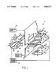
- FIG. 1is a partially exploded view of a staggered array printhead, recording medium support and capping/maintenance members in an ink jet printer;
- FIG. 2is a front view of a staggered array printhead according to the present invention.
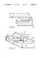
- FIG. 3is a perspective view of a basic printhead subunit of FIG. 1;
- FIG. 4is a side view of the assembly of FIG. 1;
- FIG. 5is a plan view of the recording medium support of FIG. 1;
- FIG. 6is a perspective view of a capping/maintenance member for contacting a printhead subunit
- FIG. 7is a perspective view of a high precision fixture used in the assembly of a staggered array printhead.
- FIG. 8is a side view of assembly of a staggered array printhead.
- FIGS. 1 and 2there is shown in accordance with a preferred embodiment of the present invention an assembly 10 comprising a staggered array printhead 11, a recording medium support 40 and capping/maintenance members 30 which contact the printhead.
- printer assembly support 13can be, for example, a frame to which printhead 11, recording medium support 40 and capping/maintenance members 30 are attached.
- Printer assembly support 13could then be mounted in the printer body (not shown).
- separate framescould be used to support printhead 11, recording medium support 40 and capping/maintenance members 30 or these components could be attached directly to the printer body.
- Staggered array printhead 11comprises a heat sink substrate 19 having first and second opposed surfaces on which a plurality of printhead subunits 12 are positioned.
- the printhead subunits 12are spaced apart on each surface of substrate 19 such that the subunits 12 on the first surface of substrate 19 overlie spaces on the second surface of substrate 19 and the subunits 12 on the second surface of substrate 19 overlie spaces on the first surface of substrate 19.
- This positioningforms a staggered array of printhead subunits for location close to a recording medium. See for example, U.S. Pat. No. 4,463,359 to Ayata et al, the disclosure of which is herein incorporated by reference.
- each printhead subunit 12comprises a channel plate 14 having first and second opposed surfaces and a heater plate 20 having first and second opposed surfaces.
- One surface of channel plate 14is attached to one surface of heater plate 20.
- the surface of heater plate 20 to which channel plate 14 is attachedhas a plurality of resistive heater elements 13 located thereon.
- the opposite surface of heater plate 20is attached to substrate 19.
- channel plate 14which is positioned on heater plate 20 defines ink channels 17 which form nozzles 18 at ends thereof.
- the opposite surface of channel plate 14has an ink receiving opening 15 (see FIG. 1) located therein.
- the heater elements 13 of heater plate 20correspond in number and position to the ink channels 17 in channel plate 14.
- Channel plate 14 and heater plate 20are attached to one another and a dicing action is performed to achieve coplanarity along a front face, nozzles 18 being located in the planar front face.
- Heater plate 20preferably extends beyond channel plate 14 along the remaining edges thereof (the side and rear edges). Examples of printhead subunits constructed from small heater plates and channel plates can be found in U.S. Pat. Nos. 4,774,530 to Hawkins and 4,851,371 to Fisher et al, the disclosures of which are herein incorporated by reference.
- An ink manifold 22is positioned on the subunits 12 located on each of the surfaces of heat sink substrate 19.
- Each ink manifoldincludes fingered portions 24 which extend into the spaces between subunits 12.
- the fingered portions 24each have an extreme surface defining an opening 28 therein.
- the extreme surfaceis located in close proximity to the surface of heat sink substrate 19 between each subunit 12.
- a seal 26, preferably formed of an elastomeric material,is positioned between the extreme surface of each fingered portion 24 and the surface of heat sink substrate 19, seal 26 surrounding opening 28 in the extreme surface.
- inkis more thermally conductive than air (which is what would contact heat sink 19 between each printhead subunit 12 if fingers 24 were not present) more heat is conveyed away from heat sink 19 faster than with conventional ink manifold designs. Additionally, since all of the ink within manifold 22 eventually becomes heated, the entire ink manifold 22 functions as heat sink. This permits the size (and thus weight and cost) of heat sink 19 to be reduced.
- Each manifold 22further includes openings 27 located above the ink receiving opening 15 of each channel plate 14.
- Manifold opening 27 and ink receiving opening 15provide communication between an interior of manifold 22 and an interior of each printhead subunit 12.
- a seal 16surrounds ink receiving opening 15 of each printhead subunit 12, seal 16 being positioned between manifold 22 and subunit 12.
- Seal 16is preferably formed of an elastomeric material.
- Manifold opening 28made as large as possible and is preferably larger than manifold opening 27.
- a recording medium support 40 connected to a conveying means 44operates to properly position a recording medium on which ink is to be deposited closely adjacent to the front face of printhead 11.
- the conveying means 44could comprise, for example, a supply roll and a takeup roll having recording medium support 40 in the form of a flexible endless web positioned thereabout.
- Conveying means 44could alternatively comprise a drum which rotates about a shaft in a particular direction. The surface of the drum could be provided with recording medium support 40 which presents the recording medium such that ink from printhead 11 is deposited thereon.
- recording medium support 40could be stationary, the recording medium being conveyed between support 40 and printhead 11 by a paper conveying means (not shown).
- Recording medium support 40has first and second opposed sides and a plurality of staggered openings 42 provide therethrough.
- Printhead 11is located close to a first side of recording medium support 40.
- Staggered openings 42 as illustrated in FIG. 5correspond in number and location to the printhead subunits 12 on heat sink substrate 19.
- At least one capping and/or maintenance member 30is provided on the second side of recording medium supports 40. At least one member 30 is provided for each printhead subunit 12. Each member can perform a selected service or a variety of services on the front face of a printhead subunit 12.
- a capping memberis used to cap nozzles 18 during non-use and prevent ink in the nozzles 18 from drying.
- a priming memberdraws new ink from manifold 22 into channels 17 and removes whatever substances were there before: old ink, debris, air bubbles, and/or contamination. The primary member also by this process fills the previously empty (at installation or as a result of misfunction) channels 17 with ink. After priming, a spitting or sump member could be used to clear excess ink from nozzles 18.
- the spitting processcomprises maintenance drop ejection initiated by the printhead actuator used to issue drops during printing.
- the ejection of these maintenance dropsis used to refresh aged ink in the channels, e.g. after long standing, before and after the pirnting task, and between pages.
- the ink collected within the member from spittingcan provide moisture for humidification of nozzles 18 when capped.
- the spitting membercould be used to accept the maintenance drops at predetermined times.
- conduits 33 and 35are provided to remove and supply ink, respectively, to member 30.
- a wiping membersuch as, for example, a rubber blade or a porous material can be used to wipe the nozzle-containing front face of each printhead subunit 12 to remove contaminants such as ink and dirt therefrom which tend to adversely affect print quality.
- At least one of these membersis movably positioned on the second side of recording medium support 40.
- Each memberis sized to move through at least one of openings 42 in recording medium support 40 for contact with the front face of at least one printhead subunit 12.
- Members 30can be individually movable towards and away from each printhead subunit 12 or can be mounted on a single support, such as, for example, support bar 31, so that the members for all of the printhead subunits are moved in unison towards and away from all of the printhead subunits in the staggered array.
- Individual memberscould be slidably positioned to move through openings 42 in recording medium support 40.
- a single stationcould include at least two of the members for each printhead subunit, the station being rotatably and slidably mounted and having the members positioned about a circumference thereof. Rotation of the station would cause a selected one of the members to be presented to an opening 42 in the recording medium support 40 and sliding of the station would cause the member to move through opening 42. Movement of a member 30 enables contact with a printhead subunit 12 for performance of a selected service thereon. Upon completion of the service, member 30 is moved to return to its original position, and the printing process is resumed.
- the present inventionpermits multiple operations to be performed on a printhead 11 without moving the printhead to a special position and without moving printhead 11 and recording medium support apart from each other.
- Each member 30includes a gasket 37 at its most forward portion for sealingly engaging the planar front face around each set of nozzles 18 for each printhead subunit 12.
- FIG. 4illustrates the engagement structure used to ensure secure contact between the gasket 37 of each capping and/or maintenance member 30 and a printhead subunit 12.
- the engagement structurecomprises at least two guide members 32, preferably of a resilient material, which are attached to each capping/maintenance member 30 at opposite side surfaces thereof.
- the guide members 32are moved along with member 30 to contact at least two sides of each printhead subunit 12, the subunit sides being adjacent to the front face of the subunit 12.
- Guide members 32thus provide self positioning of member 30 into secure and accurate engagement with a printhead front face.
- the locations of guide members 32ensure alignment between the gasket 37 of each member 30 and a subunit 12.
- FIG. 7illustrates a high precision fixture 50 used to facilitate the assembly of a staggered array printhead.
- Fixture 50has a bottom wall 51 and an upstanding wall 57 extending from a front portion of bottom wall 51.
- Bottom wall 51has at least one recess 52, the recess having side walls 54 which are spaced a distance from each other.
- the distance between side walls 54is greater than the distance between opposing side surfaces of channel plate 14 and less than the distance between opposing side surfaces of heater plate 20.
- Recess 52also has a bottom wall 55.
- the front and side surfaces and edges of the heater plates 20 and channel plates 14are essentially planar and straight because they are fabricated using precision dicing and ODE techniques.
- Assembly of a printhead 11is achieved by positioning an inverted printhead subunit 12 in at least one recess 52.
- An edge of channel plate 14 beyond which heater plate 20 extendsis positioned against an upper edge 53 of a side wall 54 of recess 52 indicated by arrow C in FIG. 7.
- the extensions of heater plate 20are positioned on an uppermost surface 56 of the bottom wall 51 of the fixture 50, indicated by arrows A and B, such that the extensions extend above and beyond the side walls 54 of recess 52.
- the coplanar front surfaces of heater plate 20 and channel plate 14 which contains nozzles 18are positioned against a front surface 58 of the upstanding front wall 57 of the fixture 50 indicated by arrow D.
- a first surface of substrate 19is then placed on the surface of heater plate 20 opposite from the surface containing channel plate 14.
- One side of substrate 19is positioned against the front surface 58 of upstanding front wall 57 of fixture 50.
- the surface of substrate 19 positioned on heater plate 20is then bonded thereto using, for example, a curable adhesive.
- a printhead 11 having a plurality of subunits 12 attached to a single substrate 19can be assembled. Movement of subunits against planar surfaces 56 aligns the subunits in the Z-axis direction. Movement of subunits against planar surfaces 54 aligns the subunits in the X-axis direction and movement of subunits against planar surface 58 aligns the subunits in the Y-axis direction. Additionally, since the nozzle-containing surface of each subunit 12 and surface 58 are planar, all of the subunits will be properly aligned in the 0 direction. Thus, all of the nozzles 18 will be spaced an equal distance from the recording medium.
- a staggered array printhead 11can further be assembled by providing a second high precision fixture 50 having a plurality of recesses 52 located therein. Printhead subunits 12 would likewise be positioned in each recess 52. The opposite surface of substrate 19 would then be placed on heater plates 20 of the second fixture 50 so that the printhead subunits 12 on the second fixture 50 are staggered relative to the printhead subunits 12 bonded to the first surface of substrate 19. The side of substrate 19 which was positioned against the front surface 58 of upstanding front wall 57 of the first fixture 50 would also be positioned against the front surface 58 of the upstanding front wall 57 of second fixture 50 in a like manner. The opposite surface of substrate 19 would then be bonded to the upper surface of heater plate 20 positioned on second fixture 50.
- high precision fixture 50provides precise individual positioning of subunits 12 in both the X-Y-Z planes as well as precise angular positioning in these planes. Alignment problems do not exist, and the fixture 50 is relatively inexpensive to manufacture.
- fixture 50could be used in assembling any large array printhead.
- the printhead subunitcould include any type of actuator plate and does not necessarily require a heater plate.
- an actuator plate having piezoelectric elements instead of resistive heater elementscould also be used. Accordingly, the preferred embodiments of the invention as set forth herein are intended to be illustrative, not limiting. Various changes may be made without departing from the spirit and scope of the invention as defined in the following claims.
Landscapes
- Ink Jet (AREA)
- Particle Formation And Scattering Control In Inkjet Printers (AREA)
- Recording Measured Values (AREA)
Abstract
Description
Claims (38)
Priority Applications (2)
| Application Number | Priority Date | Filing Date | Title |
|---|---|---|---|
| US07/542,053US5065170A (en) | 1990-06-22 | 1990-06-22 | Ink jet printer having a staggered array printhead |
| JP14374391AJP3208740B2 (en) | 1990-06-22 | 1991-06-17 | Zigzag arrangement inkjet print head |
Applications Claiming Priority (1)
| Application Number | Priority Date | Filing Date | Title |
|---|---|---|---|
| US07/542,053US5065170A (en) | 1990-06-22 | 1990-06-22 | Ink jet printer having a staggered array printhead |
Publications (1)
| Publication Number | Publication Date |
|---|---|
| US5065170Atrue US5065170A (en) | 1991-11-12 |
Family
ID=24162150
Family Applications (1)
| Application Number | Title | Priority Date | Filing Date |
|---|---|---|---|
| US07/542,053Expired - Fee RelatedUS5065170A (en) | 1990-06-22 | 1990-06-22 | Ink jet printer having a staggered array printhead |
Country Status (2)
| Country | Link |
|---|---|
| US (1) | US5065170A (en) |
| JP (1) | JP3208740B2 (en) |
Cited By (29)
| Publication number | Priority date | Publication date | Assignee | Title |
|---|---|---|---|---|
| US5192959A (en)* | 1991-06-03 | 1993-03-09 | Xerox Corporation | Alignment of pagewidth bars |
| US5257043A (en)* | 1991-12-09 | 1993-10-26 | Xerox Corporation | Thermal ink jet nozzle arrays |
| DE4330798A1 (en)* | 1992-09-10 | 1994-03-17 | Seiko Epson Corp | printer |
| US5333007A (en)* | 1991-10-17 | 1994-07-26 | Xerox Corporation | Moisture leakage resistant capping surface for ink jet printhead |
| US5534897A (en)* | 1993-07-01 | 1996-07-09 | Xerox Corporation | Ink jet maintenance subsystem |
| US5730049A (en)* | 1996-01-05 | 1998-03-24 | Pitney Bowes Inc. | Method and apparatus for high speed printing in a mailing machine |
| US5933163A (en)* | 1994-03-04 | 1999-08-03 | Canon Kabushiki Kaisha | Ink jet recording apparatus |
| US6116714A (en)* | 1994-03-04 | 2000-09-12 | Canon Kabushiki Kaisha | Printing head, printing method and apparatus using same, and apparatus and method for correcting said printing head |
| US6145951A (en)* | 1995-02-23 | 2000-11-14 | Canon Kabushiki Kaisha | Method and apparatus for correcting printhead, printhead corrected by this apparatus, and printing apparatus using this printhead |
| US20020040354A1 (en)* | 2000-09-29 | 2002-04-04 | Neopost Industrie | High-rate franking machine |
| US6471335B1 (en) | 2001-08-06 | 2002-10-29 | Creo Inc. | Method for mutual spatial registration of inkjet cartridges |
| US6481836B1 (en) | 1996-06-10 | 2002-11-19 | Moore Business Forms, Inc. | Modular ink mounting assembly and ink delivery system |
| US6523932B2 (en) | 2001-01-14 | 2003-02-25 | Hewlett-Packard Company | Periodic ejection of printing fluid to service orifices of an inkjet printer |
| US6820966B1 (en) | 1998-10-24 | 2004-11-23 | Xaar Technology Limited | Droplet deposition apparatus |
| US20060001704A1 (en)* | 2004-06-30 | 2006-01-05 | Anderson Frank E | Multi-fluid ejection device |
| US20070121178A1 (en)* | 1998-11-09 | 2007-05-31 | Silverbrook Research Pty Ltd | Mobile communications device with integral internal replaceable printhead assembly |
| US20090086003A1 (en)* | 2001-01-17 | 2009-04-02 | Silverbrook Research Pty Ltd | Hand held personal digital assistant having an internal printer |
| US20110025775A1 (en)* | 2009-07-31 | 2011-02-03 | Silverbrook Research Pty Ltd | Wide format printer with aerosol collection from both sides of media path |
| US8789939B2 (en) | 1998-11-09 | 2014-07-29 | Google Inc. | Print media cartridge with ink supply manifold |
| US8823823B2 (en) | 1997-07-15 | 2014-09-02 | Google Inc. | Portable imaging device with multi-core processor and orientation sensor |
| US8866923B2 (en) | 1999-05-25 | 2014-10-21 | Google Inc. | Modular camera and printer |
| US8896724B2 (en) | 1997-07-15 | 2014-11-25 | Google Inc. | Camera system to facilitate a cascade of imaging effects |
| US8902340B2 (en) | 1997-07-12 | 2014-12-02 | Google Inc. | Multi-core image processor for portable device |
| US8902333B2 (en) | 1997-07-15 | 2014-12-02 | Google Inc. | Image processing method using sensed eye position |
| US8908075B2 (en) | 1997-07-15 | 2014-12-09 | Google Inc. | Image capture and processing integrated circuit for a camera |
| US8936196B2 (en) | 1997-07-15 | 2015-01-20 | Google Inc. | Camera unit incorporating program script scanner |
| EP2862719A1 (en)* | 2013-09-20 | 2015-04-22 | Canon Finetech Inc. | Inkjet printing apparatus and method for controlling inkjet printing apparatus |
| US9055221B2 (en) | 1997-07-15 | 2015-06-09 | Google Inc. | Portable hand-held device for deblurring sensed images |
| US10265910B2 (en) | 2010-10-27 | 2019-04-23 | Rize Inc. | Process and apparatus for fabrication of three-dimensional objects |
Families Citing this family (9)
| Publication number | Priority date | Publication date | Assignee | Title |
|---|---|---|---|---|
| JPH08118727A (en) | 1994-10-28 | 1996-05-14 | Canon Inc | Recording head correction method and apparatus, recording head corrected by the apparatus, and recording apparatus using the recording head |
| JP3174226B2 (en)* | 1994-10-28 | 2001-06-11 | キヤノン株式会社 | Printhead correction method and apparatus, printhead corrected by the apparatus, and printing apparatus using the printhead |
| US6062666A (en) | 1994-11-07 | 2000-05-16 | Canon Kabushiki Kaisha | Ink jet recording method and apparatus beginning driving cycle with discharge elements other than at ends of substrates |
| JP3552004B2 (en)* | 1996-09-24 | 2004-08-11 | セイコーエプソン株式会社 | Ink jet line recording head and recording apparatus |
| EP0925925A3 (en) | 1997-12-26 | 2000-01-19 | Canon Kabushiki Kaisha | Method for correcting a recording head, correction apparatus therefor, recording head corrected by use of such apparatus, and recording apparatus using such recording head |
| JP2000085117A (en) | 1998-09-10 | 2000-03-28 | Canon Inc | Recording head correction method and apparatus, recording head corrected by the apparatus, and recording apparatus using the recording head |
| JP2005081591A (en)* | 2003-09-05 | 2005-03-31 | Fuji Xerox Co Ltd | Recording apparatus |
| JP4543681B2 (en)* | 2004-01-15 | 2010-09-15 | 富士ゼロックス株式会社 | Inkjet recording device |
| JP4645138B2 (en)* | 2004-09-30 | 2011-03-09 | コニカミノルタホールディングス株式会社 | Inkjet recording device |
Citations (12)
| Publication number | Priority date | Publication date | Assignee | Title |
|---|---|---|---|---|
| US4144537A (en)* | 1976-06-07 | 1979-03-13 | Konishiroku Photo Industry Co., Ltd. | Method and apparatus for capping a nozzle of ink jet recording device |
| US4369456A (en)* | 1981-08-26 | 1983-01-18 | Pitney Bowes Inc. | Cleaning device for writing heads used in ink jet recorders and printers |
| JPS59115863A (en)* | 1982-12-23 | 1984-07-04 | Nec Corp | Plane scanning type ink jet recording apparatus |
| US4463359A (en)* | 1979-04-02 | 1984-07-31 | Canon Kabushiki Kaisha | Droplet generating method and apparatus thereof |
| US4559543A (en)* | 1981-10-13 | 1985-12-17 | Canon Kabushiki Kaisha | Ink jet recording device modular frame |
| US4571599A (en)* | 1984-12-03 | 1986-02-18 | Xerox Corporation | Ink cartridge for an ink jet printer |
| US4703333A (en)* | 1986-01-30 | 1987-10-27 | Pitney Bowes Inc. | Impulse ink jet print head with inclined and stacked arrays |
| US4745414A (en)* | 1986-04-09 | 1988-05-17 | Canon Kabushiki Kaisha | Recovery device for an ink jet recorder and a recovery method thereof |
| US4774530A (en)* | 1987-11-02 | 1988-09-27 | Xerox Corporation | Ink jet printhead |
| US4829324A (en)* | 1987-12-23 | 1989-05-09 | Xerox Corporation | Large array thermal ink jet printhead |
| US4853717A (en)* | 1987-10-23 | 1989-08-01 | Hewlett-Packard Company | Service station for ink-jet printer |
| US4935750A (en)* | 1989-08-31 | 1990-06-19 | Xerox Corporation | Sealing means for thermal ink jet printheads |
- 1990
- 1990-06-22USUS07/542,053patent/US5065170A/ennot_activeExpired - Fee Related
- 1991
- 1991-06-17JPJP14374391Apatent/JP3208740B2/ennot_activeExpired - Lifetime
Patent Citations (12)
| Publication number | Priority date | Publication date | Assignee | Title |
|---|---|---|---|---|
| US4144537A (en)* | 1976-06-07 | 1979-03-13 | Konishiroku Photo Industry Co., Ltd. | Method and apparatus for capping a nozzle of ink jet recording device |
| US4463359A (en)* | 1979-04-02 | 1984-07-31 | Canon Kabushiki Kaisha | Droplet generating method and apparatus thereof |
| US4369456A (en)* | 1981-08-26 | 1983-01-18 | Pitney Bowes Inc. | Cleaning device for writing heads used in ink jet recorders and printers |
| US4559543A (en)* | 1981-10-13 | 1985-12-17 | Canon Kabushiki Kaisha | Ink jet recording device modular frame |
| JPS59115863A (en)* | 1982-12-23 | 1984-07-04 | Nec Corp | Plane scanning type ink jet recording apparatus |
| US4571599A (en)* | 1984-12-03 | 1986-02-18 | Xerox Corporation | Ink cartridge for an ink jet printer |
| US4703333A (en)* | 1986-01-30 | 1987-10-27 | Pitney Bowes Inc. | Impulse ink jet print head with inclined and stacked arrays |
| US4745414A (en)* | 1986-04-09 | 1988-05-17 | Canon Kabushiki Kaisha | Recovery device for an ink jet recorder and a recovery method thereof |
| US4853717A (en)* | 1987-10-23 | 1989-08-01 | Hewlett-Packard Company | Service station for ink-jet printer |
| US4774530A (en)* | 1987-11-02 | 1988-09-27 | Xerox Corporation | Ink jet printhead |
| US4829324A (en)* | 1987-12-23 | 1989-05-09 | Xerox Corporation | Large array thermal ink jet printhead |
| US4935750A (en)* | 1989-08-31 | 1990-06-19 | Xerox Corporation | Sealing means for thermal ink jet printheads |
Cited By (106)
| Publication number | Priority date | Publication date | Assignee | Title |
|---|---|---|---|---|
| US5192959A (en)* | 1991-06-03 | 1993-03-09 | Xerox Corporation | Alignment of pagewidth bars |
| US5333007A (en)* | 1991-10-17 | 1994-07-26 | Xerox Corporation | Moisture leakage resistant capping surface for ink jet printhead |
| US5257043A (en)* | 1991-12-09 | 1993-10-26 | Xerox Corporation | Thermal ink jet nozzle arrays |
| DE4330798A1 (en)* | 1992-09-10 | 1994-03-17 | Seiko Epson Corp | printer |
| US5534897A (en)* | 1993-07-01 | 1996-07-09 | Xerox Corporation | Ink jet maintenance subsystem |
| US6409300B2 (en) | 1994-03-04 | 2002-06-25 | Canon Kabushiki Kaisha | Printing head, printing method and apparatus using same, and apparatus and method for correcting said printing head |
| US6616257B2 (en) | 1994-03-04 | 2003-09-09 | Canon Kabushiki Kaisha | Printing head, printing method and apparatus using same, and apparatus and method for correcting said printing head |
| US5933163A (en)* | 1994-03-04 | 1999-08-03 | Canon Kabushiki Kaisha | Ink jet recording apparatus |
| US6116714A (en)* | 1994-03-04 | 2000-09-12 | Canon Kabushiki Kaisha | Printing head, printing method and apparatus using same, and apparatus and method for correcting said printing head |
| US6145951A (en)* | 1995-02-23 | 2000-11-14 | Canon Kabushiki Kaisha | Method and apparatus for correcting printhead, printhead corrected by this apparatus, and printing apparatus using this printhead |
| US5730049A (en)* | 1996-01-05 | 1998-03-24 | Pitney Bowes Inc. | Method and apparatus for high speed printing in a mailing machine |
| US6481836B1 (en) | 1996-06-10 | 2002-11-19 | Moore Business Forms, Inc. | Modular ink mounting assembly and ink delivery system |
| US9544451B2 (en) | 1997-07-12 | 2017-01-10 | Google Inc. | Multi-core image processor for portable device |
| US9338312B2 (en) | 1997-07-12 | 2016-05-10 | Google Inc. | Portable handheld device with multi-core image processor |
| US8902340B2 (en) | 1997-07-12 | 2014-12-02 | Google Inc. | Multi-core image processor for portable device |
| US8947592B2 (en) | 1997-07-12 | 2015-02-03 | Google Inc. | Handheld imaging device with image processor provided with multiple parallel processing units |
| US9060128B2 (en) | 1997-07-15 | 2015-06-16 | Google Inc. | Portable hand-held device for manipulating images |
| US9137398B2 (en) | 1997-07-15 | 2015-09-15 | Google Inc. | Multi-core processor for portable device with dual image sensors |
| US9584681B2 (en) | 1997-07-15 | 2017-02-28 | Google Inc. | Handheld imaging device incorporating multi-core image processor |
| US9560221B2 (en) | 1997-07-15 | 2017-01-31 | Google Inc. | Handheld imaging device with VLIW image processor |
| US9432529B2 (en) | 1997-07-15 | 2016-08-30 | Google Inc. | Portable handheld device with multi-core microcoded image processor |
| US9237244B2 (en) | 1997-07-15 | 2016-01-12 | Google Inc. | Handheld digital camera device with orientation sensing and decoding capabilities |
| US9219832B2 (en) | 1997-07-15 | 2015-12-22 | Google Inc. | Portable handheld device with multi-core image processor |
| US9197767B2 (en) | 1997-07-15 | 2015-11-24 | Google Inc. | Digital camera having image processor and printer |
| US9191530B2 (en) | 1997-07-15 | 2015-11-17 | Google Inc. | Portable hand-held device having quad core image processor |
| US9191529B2 (en) | 1997-07-15 | 2015-11-17 | Google Inc | Quad-core camera processor |
| US9185247B2 (en) | 1997-07-15 | 2015-11-10 | Google Inc. | Central processor with multiple programmable processor units |
| US9185246B2 (en) | 1997-07-15 | 2015-11-10 | Google Inc. | Camera system comprising color display and processor for decoding data blocks in printed coding pattern |
| US9179020B2 (en) | 1997-07-15 | 2015-11-03 | Google Inc. | Handheld imaging device with integrated chip incorporating on shared wafer image processor and central processor |
| US9168761B2 (en) | 1997-07-15 | 2015-10-27 | Google Inc. | Disposable digital camera with printing assembly |
| US9148530B2 (en) | 1997-07-15 | 2015-09-29 | Google Inc. | Handheld imaging device with multi-core image processor integrating common bus interface and dedicated image sensor interface |
| US9143635B2 (en) | 1997-07-15 | 2015-09-22 | Google Inc. | Camera with linked parallel processor cores |
| US9143636B2 (en) | 1997-07-15 | 2015-09-22 | Google Inc. | Portable device with dual image sensors and quad-core processor |
| US9137397B2 (en) | 1997-07-15 | 2015-09-15 | Google Inc. | Image sensing and printing device |
| US9131083B2 (en) | 1997-07-15 | 2015-09-08 | Google Inc. | Portable imaging device with multi-core processor |
| US9124737B2 (en) | 1997-07-15 | 2015-09-01 | Google Inc. | Portable device with image sensor and quad-core processor for multi-point focus image capture |
| US9124736B2 (en) | 1997-07-15 | 2015-09-01 | Google Inc. | Portable hand-held device for displaying oriented images |
| US9055221B2 (en) | 1997-07-15 | 2015-06-09 | Google Inc. | Portable hand-held device for deblurring sensed images |
| US8953060B2 (en) | 1997-07-15 | 2015-02-10 | Google Inc. | Hand held image capture device with multi-core processor and wireless interface to input device |
| US8953178B2 (en) | 1997-07-15 | 2015-02-10 | Google Inc. | Camera system with color display and processor for reed-solomon decoding |
| US8953061B2 (en) | 1997-07-15 | 2015-02-10 | Google Inc. | Image capture device with linked multi-core processor and orientation sensor |
| US8947679B2 (en) | 1997-07-15 | 2015-02-03 | Google Inc. | Portable handheld device with multi-core microcoded image processor |
| US8937727B2 (en) | 1997-07-15 | 2015-01-20 | Google Inc. | Portable handheld device with multi-core image processor |
| US8936196B2 (en) | 1997-07-15 | 2015-01-20 | Google Inc. | Camera unit incorporating program script scanner |
| US8934053B2 (en) | 1997-07-15 | 2015-01-13 | Google Inc. | Hand-held quad core processing apparatus |
| US8934027B2 (en) | 1997-07-15 | 2015-01-13 | Google Inc. | Portable device with image sensors and multi-core processor |
| US8928897B2 (en) | 1997-07-15 | 2015-01-06 | Google Inc. | Portable handheld device with multi-core image processor |
| US8922670B2 (en) | 1997-07-15 | 2014-12-30 | Google Inc. | Portable hand-held device having stereoscopic image camera |
| US8823823B2 (en) | 1997-07-15 | 2014-09-02 | Google Inc. | Portable imaging device with multi-core processor and orientation sensor |
| US8836809B2 (en) | 1997-07-15 | 2014-09-16 | Google Inc. | Quad-core image processor for facial detection |
| US8866926B2 (en) | 1997-07-15 | 2014-10-21 | Google Inc. | Multi-core processor for hand-held, image capture device |
| US8922791B2 (en) | 1997-07-15 | 2014-12-30 | Google Inc. | Camera system with color display and processor for Reed-Solomon decoding |
| US8896720B2 (en) | 1997-07-15 | 2014-11-25 | Google Inc. | Hand held image capture device with multi-core processor for facial detection |
| US8896724B2 (en) | 1997-07-15 | 2014-11-25 | Google Inc. | Camera system to facilitate a cascade of imaging effects |
| US8913182B2 (en) | 1997-07-15 | 2014-12-16 | Google Inc. | Portable hand-held device having networked quad core processor |
| US8902333B2 (en) | 1997-07-15 | 2014-12-02 | Google Inc. | Image processing method using sensed eye position |
| US8902324B2 (en) | 1997-07-15 | 2014-12-02 | Google Inc. | Quad-core image processor for device with image display |
| US8902357B2 (en) | 1997-07-15 | 2014-12-02 | Google Inc. | Quad-core image processor |
| US8908051B2 (en) | 1997-07-15 | 2014-12-09 | Google Inc. | Handheld imaging device with system-on-chip microcontroller incorporating on shared wafer image processor and image sensor |
| US8908075B2 (en) | 1997-07-15 | 2014-12-09 | Google Inc. | Image capture and processing integrated circuit for a camera |
| US8908069B2 (en) | 1997-07-15 | 2014-12-09 | Google Inc. | Handheld imaging device with quad-core image processor integrating image sensor interface |
| US8913151B2 (en) | 1997-07-15 | 2014-12-16 | Google Inc. | Digital camera with quad core processor |
| US8913137B2 (en) | 1997-07-15 | 2014-12-16 | Google Inc. | Handheld imaging device with multi-core image processor integrating image sensor interface |
| US6820966B1 (en) | 1998-10-24 | 2004-11-23 | Xaar Technology Limited | Droplet deposition apparatus |
| US8789939B2 (en) | 1998-11-09 | 2014-07-29 | Google Inc. | Print media cartridge with ink supply manifold |
| US20070121177A1 (en)* | 1998-11-09 | 2007-05-31 | Silverbrook Research Pty Ltd | Mobile communications device with printhead and ink supply module |
| US20070121178A1 (en)* | 1998-11-09 | 2007-05-31 | Silverbrook Research Pty Ltd | Mobile communications device with integral internal replaceable printhead assembly |
| US8866923B2 (en) | 1999-05-25 | 2014-10-21 | Google Inc. | Modular camera and printer |
| US20020040354A1 (en)* | 2000-09-29 | 2002-04-04 | Neopost Industrie | High-rate franking machine |
| US7925596B2 (en)* | 2000-09-29 | 2011-04-12 | Neopost Industrie | High-rate franking machine |
| US6523932B2 (en) | 2001-01-14 | 2003-02-25 | Hewlett-Packard Company | Periodic ejection of printing fluid to service orifices of an inkjet printer |
| US20100220168A1 (en)* | 2001-01-17 | 2010-09-02 | Silverbrook Research Pty Ltd | Mobile computing device incorporating printer and print media roll |
| US7984986B2 (en) | 2001-01-17 | 2011-07-26 | Silverbrook Research Pty Ltd | Hand held personal digital assistant having an internal printer |
| US20090086003A1 (en)* | 2001-01-17 | 2009-04-02 | Silverbrook Research Pty Ltd | Hand held personal digital assistant having an internal printer |
| US20090244010A1 (en)* | 2001-01-17 | 2009-10-01 | Silverbrook Research Pty Ltd | Personal digital assistant having printhead |
| US20100002064A1 (en)* | 2001-01-17 | 2010-01-07 | Silverbrook Research Pty Ltd | Device having Printer and Supply of Print Media in a hinge of the Device |
| US7934829B2 (en) | 2001-01-17 | 2011-05-03 | Silverbrook Research Pty Ltd | Mobile computing device incorporating printer and print media roll |
| US7954940B2 (en) | 2001-01-17 | 2011-06-07 | Silverbrook Research Pty Ltd | Personal digital assistant having printhead |
| US6471335B1 (en) | 2001-08-06 | 2002-10-29 | Creo Inc. | Method for mutual spatial registration of inkjet cartridges |
| US20060001704A1 (en)* | 2004-06-30 | 2006-01-05 | Anderson Frank E | Multi-fluid ejection device |
| US7267431B2 (en) | 2004-06-30 | 2007-09-11 | Lexmark International, Inc. | Multi-fluid ejection device |
| US20110025747A1 (en)* | 2009-07-31 | 2011-02-03 | Silverbrook Research Pty Ltd | Printing system for media of different sizes |
| US8540361B2 (en) | 2009-07-31 | 2013-09-24 | Zamtec Ltd | Printing system with input media roller and output vacuum belts |
| US8641168B2 (en) | 2009-07-31 | 2014-02-04 | Zamtec Ltd | Printing system with adjustable aerosol collection |
| US20110025798A1 (en)* | 2009-07-31 | 2011-02-03 | Silverbrook Research Pty Ltd | Printing system with input media roller and output vacuum belts |
| US20110025799A1 (en)* | 2009-07-31 | 2011-02-03 | Silverbrook Research Pty Ltd | Printing system with scanner to align printhead assembly |
| US20110026058A1 (en)* | 2009-07-31 | 2011-02-03 | Silverbrook Research Pty Ltd | Printing system with adjustable aerosol collection |
| US20110026057A1 (en)* | 2009-07-31 | 2011-02-03 | Silverbrook Research Pty Ltd | Printing system with input roller and movable media engagement output |
| US20110025802A1 (en)* | 2009-07-31 | 2011-02-03 | Silverbrook Research Pty Ltd | Printing system with independently movable printhead service modules |
| US20110025755A1 (en)* | 2009-07-31 | 2011-02-03 | Silverbrook Research Pty Ltd | Wide format printer with independently operable printhead service modules |
| US20110025754A1 (en)* | 2009-07-31 | 2011-02-03 | Silverbrook Research Pty Ltd | Printing system with independently operable printhead service modules |
| US8567939B2 (en) | 2009-07-31 | 2013-10-29 | Zamtec Ltd | Printing system with independently movable printhead service modules |
| US20110025775A1 (en)* | 2009-07-31 | 2011-02-03 | Silverbrook Research Pty Ltd | Wide format printer with aerosol collection from both sides of media path |
| US8579430B2 (en) | 2009-07-31 | 2013-11-12 | Zamtec Ltd | Wide format printer with aerosol collection from both sides of media path |
| US8550617B2 (en) | 2009-07-31 | 2013-10-08 | Zamtec Ltd | Printing system with scanner to align printhead assembly |
| US8746832B2 (en) | 2009-07-31 | 2014-06-10 | Zamtec Ltd | Printer having fixed vacuum platen and moving belt assembly |
| US8567898B2 (en) | 2009-07-31 | 2013-10-29 | Zamtec Ltd | Printing system with input roller and movable media engagement output |
| US8556368B2 (en) | 2009-07-31 | 2013-10-15 | Zamtec Ltd | Printing system for media of different sizes |
| US8567899B2 (en) | 2009-07-31 | 2013-10-29 | Zamtec Ltd | Printing system with independently operable printhead service modules |
| US8646864B2 (en) | 2009-07-31 | 2014-02-11 | Zamtec Ltd | Wide format printer with input roller and movable media engagement output for simultaneously engaging media |
| US10265910B2 (en) | 2010-10-27 | 2019-04-23 | Rize Inc. | Process and apparatus for fabrication of three-dimensional objects |
| US10357918B2 (en) | 2010-10-27 | 2019-07-23 | Rize Inc. | Process and apparatus for fabrication of three dimensional objects |
| US11148354B2 (en) | 2010-10-27 | 2021-10-19 | Rize, Inc. | Process and apparatus for fabrication of three dimensional objects |
| US9421775B2 (en) | 2013-09-20 | 2016-08-23 | Canon Finetech Inc. | Inkjet printing apparatus and method for controlling inkjet printing apparatus |
| EP2862719A1 (en)* | 2013-09-20 | 2015-04-22 | Canon Finetech Inc. | Inkjet printing apparatus and method for controlling inkjet printing apparatus |
| US9827766B2 (en) | 2013-09-20 | 2017-11-28 | Canon Finetech Inc. | Inkjet printing apparatus and method for controlling inkjet printing apparatus |
Also Published As
| Publication number | Publication date |
|---|---|
| JPH04232749A (en) | 1992-08-21 |
| JP3208740B2 (en) | 2001-09-17 |
Similar Documents
| Publication | Publication Date | Title |
|---|---|---|
| US5065170A (en) | Ink jet printer having a staggered array printhead | |
| JP2891797B2 (en) | Inkjet printer | |
| US5574485A (en) | Ultrasonic liquid wiper for ink jet printhead maintenance | |
| EP0621136B1 (en) | Wet-wipe maintenance device for a full-width ink jet printer | |
| US5670997A (en) | Recording means for enhancing removal of ink deposited on an ejection side surface thereof, ink jet recording apparatus having said recording means, and recovery method | |
| US5160945A (en) | Pagewidth thermal ink jet printhead | |
| US5555461A (en) | Self cleaning wiper blade for cleaning nozzle faces of ink jet printheads | |
| US7901033B2 (en) | Capping device, and recovery device having the same | |
| US6464327B1 (en) | Replaceable snout wiper for inkjet cartridges | |
| JPH03262646A (en) | Ink jet recording apparatus | |
| JPH07246708A (en) | Inkjet recording device | |
| EP1518689B1 (en) | Inkjet printer | |
| JP3007395B2 (en) | Thermal inkjet printer system | |
| US6669325B2 (en) | Apparatus and method for placing fluid droplets onto an object | |
| CA2364396A1 (en) | Inkjet printer with nozzle maintenance system in printing media carrier | |
| US6517187B1 (en) | Method and apparatus for cleaning residual ink from printhead nozzle faces | |
| JP3234087B2 (en) | Ink jet recording device | |
| JP2000177113A (en) | Ink jet recording device | |
| JP3155838B2 (en) | Ink jet recording device | |
| US6276793B1 (en) | Ink jet printer having a wear resistant and efficient substrate heating and supporting assembly | |
| JPH0839828A (en) | Inkjet recording means and recording apparatus | |
| JP4642184B2 (en) | Inkjet recording device | |
| JPH07290716A (en) | Inkjet recording device | |
| JP2705960B2 (en) | INK JET RECORDING APPARATUS AND METHOD OF WIPING DISCHARGE PORTS IN THE APPARATUS | |
| JPH03227646A (en) | Inkjet recording device with multiple recording heads |
Legal Events
| Date | Code | Title | Description |
|---|---|---|---|
| AS | Assignment | Owner name:XEROX CORPORATION, CONNECTICUT Free format text:ASSIGNMENT OF ASSIGNORS INTEREST.;ASSIGNORS:REZANKA, IVAN;HORINO, YASUO;REEL/FRAME:005462/0293;SIGNING DATES FROM 19900620 TO 19900719 | |
| FPAY | Fee payment | Year of fee payment:4 | |
| FPAY | Fee payment | Year of fee payment:8 | |
| AS | Assignment | Owner name:BANK ONE, NA, AS ADMINISTRATIVE AGENT, ILLINOIS Free format text:SECURITY INTEREST;ASSIGNOR:XEROX CORPORATION;REEL/FRAME:013153/0001 Effective date:20020621 | |
| REMI | Maintenance fee reminder mailed | ||
| AS | Assignment | Owner name:JPMORGAN CHASE BANK, AS COLLATERAL AGENT, TEXAS Free format text:SECURITY AGREEMENT;ASSIGNOR:XEROX CORPORATION;REEL/FRAME:015134/0476 Effective date:20030625 Owner name:JPMORGAN CHASE BANK, AS COLLATERAL AGENT,TEXAS Free format text:SECURITY AGREEMENT;ASSIGNOR:XEROX CORPORATION;REEL/FRAME:015134/0476 Effective date:20030625 | |
| LAPS | Lapse for failure to pay maintenance fees | ||
| STCH | Information on status: patent discontinuation | Free format text:PATENT EXPIRED DUE TO NONPAYMENT OF MAINTENANCE FEES UNDER 37 CFR 1.362 | |
| FP | Lapsed due to failure to pay maintenance fee | Effective date:20031112 | |
| AS | Assignment | Owner name:XEROX CORPORATION, CONNECTICUT Free format text:RELEASE BY SECURED PARTY;ASSIGNOR:JPMORGAN CHASE BANK, N.A. AS SUCCESSOR-IN-INTEREST ADMINISTRATIVE AGENT AND COLLATERAL AGENT TO JPMORGAN CHASE BANK;REEL/FRAME:066728/0193 Effective date:20220822 |