US5065145A - Method and apparatus for producing signals corresponding to the position of a cursor - Google Patents
Method and apparatus for producing signals corresponding to the position of a cursorDownload PDFInfo
- Publication number
- US5065145A US5065145AUS07/418,167US41816789AUS5065145AUS 5065145 AUS5065145 AUS 5065145AUS 41816789 AUS41816789 AUS 41816789AUS 5065145 AUS5065145 AUS 5065145A
- Authority
- US
- United States
- Prior art keywords
- cursor
- linear
- gantry
- sensing
- carriage
- Prior art date
- Legal status (The legal status is an assumption and is not a legal conclusion. Google has not performed a legal analysis and makes no representation as to the accuracy of the status listed.)
- Expired - Fee Related
Links
Images


Classifications
- G—PHYSICS
- G06—COMPUTING OR CALCULATING; COUNTING
- G06F—ELECTRIC DIGITAL DATA PROCESSING
- G06F3/00—Input arrangements for transferring data to be processed into a form capable of being handled by the computer; Output arrangements for transferring data from processing unit to output unit, e.g. interface arrangements
- G06F3/01—Input arrangements or combined input and output arrangements for interaction between user and computer
- G06F3/03—Arrangements for converting the position or the displacement of a member into a coded form
- G06F3/041—Digitisers, e.g. for touch screens or touch pads, characterised by the transducing means
- G06F3/042—Digitisers, e.g. for touch screens or touch pads, characterised by the transducing means by opto-electronic means
- G06F3/0421—Digitisers, e.g. for touch screens or touch pads, characterised by the transducing means by opto-electronic means by interrupting or reflecting a light beam, e.g. optical touch-screen
Definitions
- This inventionrelates to a method and apparatus for providing signals corresponding to the position of a cursor or the like, the apparatus being especially adapted to provide digital output signals, and/or a display, indicating the position of cross hairs or the like of a cursor on a planar surface, such as a drafting board, map, illustration, etc. It is of course apparent that the invention is not limited to these applications.
- the present inventionis therefore directed to the provision of an improved method and arrangement for developing signals corresponding to the position or displacement of a cursor or the like, for example with reference to a surface.
- the inventionprovides a system for indicating the position of a cursor on a surface in first and second different directions, the cursor being mounted on a member such as a gantry or the like.
- a carriage or the likeis guided for movement in the first direction, for example on a rail adapted to be held fixed with respect to the surface.
- the gantryis guided by the carriage for movement in the second direction.
- Spaced sensing regionssuch as a pair of mirror strips are provided on the gantry, the strips being uniquely spaced for each displacement of the cursor in the second direction.
- Sensing meansare mounted on a locus adjacent the first and second regions and extending in the first direction for sensing the displacements of adjacent portions of the first and second regions along the locus.
- the sensing meansmay be mounted on the rail.
- the mirror stripsmay extend at an acute angle to one another, to provide the unique spacing thereof.
- the sensing meansmay comprise a linear light source mounted to direct light toward the gantry, and a linear detector array positioned to receive light reflected from the mirror strips.
- the gantrymay be mounted to the carriage by a shaft mounted thereto and extending in the second direction, and linear bearings on the carriage for receiving and guiding the shaft.
- a microcomputermay be coupled to the linear detector array for calculating the position of the cursor by triangulation.
- the microcomputer, and a display for the calculated location,may be mounted to the rail.
- a switchmay be mounted on the gantry and connected to the microcomputer for initiating the steps of computing the location of the cursor.
- the gantryis guided to move linearly parallel to the surface in the second direction, and the carriage is guided to move orthogonal to the first direction and parallel to the surface.
- a linear light extending in the first directiondirects light toward the gantry, thereby reflecting light from the mirrors strips at two positions that are uniquely spaced as a function of the location thereof in the second direction. This light is received, and the coordinates of the cursor are calculated from the detected spacing of the two positions and the absolute location of one of the two positions, by triangulation.
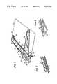
- FIG. 1is a perspective view of a drafting device in accordance with the invention
- FIG. 2is a top view of the drafting device of FIG. 1, illustrating one position of the gantry in solid lines and another position of the gantry in dash-dot lines;
- FIG. 3is a cross sectional view of the drafting device of FIG. 2 taken along the line 3--3;
- FIG. 4is a cross sectional view of the drafting device of FIG. 2 taken along the line 4--4;
- FIG. 5is a cross sectional view of the drafting device of FIG. 2 taken along the line 5--5;
- FIG. 6is an enlarged perspective view of a modification of the hinge arrangement of FIGS. 1-3;
- FIG. 7is a perspective view of a portion of a light source that may be used with the invention.
- FIG. 8is a perspective view of a portion of a light detector that may be used with the invention.
- FIG. 9is a block diagram of a circuit in accordance with the invention/ and
- FIG. 10is a view illustrating various positions of the cursor, to explain the operation of the invention.
- a coordinate determining devicein accordance with one embodiment of the invention comprises a digital drafting device having a rail 10 adapted to be mounted to a drafting board 11 or the like, for example to extend along the rear edge of the drafting board.
- the rail 10is provided with a clamp 12 at each end and adapted to receive the rear edge 13 of the board, with an adjusting screw 14 extending into the clamp from the underside thereof and adapted to be threaded against the underside of the board.
- the top of the rail 10is preferably held in a plane slightly above the plane of the top surface of the drafting board 11.
- a carriage 20is mounted for precise longitudinal movement along the rail, i.e. in a direction indicated by the arrow 18, hereinafter referred to as the X direction.
- bearingsmay be mounted to extend downwardly from the carriage to engage the front and rear edges of the rail.
- first and second roller bearings 21,22are spaced apart longitudinally of the rail and pivoted about vertical axes, so that their bearing surfaces engage the rear edge surface 24 of the rail.
- a third roller bearing 23is mounted on a vertical axis intermediate the first and second bearings, with respect to the longitudinal direction of the rail, to roll on the front edge 25 of the rail.
- the bearingsmay ride on ridges or the like on the edges of the rail, as illustrated, to inhibit removal of the carriage from the rail.
- an air bearingmay be employed for this purpose.
- the carriage 20may be provided with a pair of linear bearings 31,32 spaced in the transverse direction of the rail, for receiving and guiding a rod or shaft 33 for movement longitudinally of the rod, i.e. transversely of the rail.
- the shaft 33is affixed to the gantry 30 by clamps 35,36 at the ends thereof that hold the gantry spaced in the X direction from the shaft, to permit the shaft to be moved with precision in the Y direction, the clamps 35,36 also serving as stops to limit the extent of the permissible displacement of the gantry with respect to the carriage in the Y direction.
- One of the clampspreferably the upper clamp 36, may be releasably fastened to the gantry by any conventional means, e.g. by wing nuts, snaps, etc., so that it can be pivoted out of clamping relationship with the shaft, to enable removal of the shaft and gantry assembly from the carriage.
- any conventional meanse.g. by wing nuts, snaps, etc.
- other arrangementsmay be provided to permit such separation of the elements of the drafting device for moving, storage, or replacement of parts. It is of course apparent that the shaft 33 need not have a round cross section.
- shaft 33may be replaced by an enlarged rounded edge 38 formed integrally with the gantry.
- the linear bearings on the carriageare of course slotted to receive the rod.
- the gantrymay be right triangular shaped, as illustrated, with for example the right edge 40 thereof extending straight in the Y direction, and the upper edge 41 extending in the X direction.
- a pointer or cursor 42is mounted on or formed in the gantry at the lower peak, or apex thereof.
- the cursor 42preferably has cross hairs 43 or the like to permit visual alignment of the cursor with a desired feature on the drafting board, by manual movement of the gantry in the X and Y directions.
- the gantrymay of course have a shape other than triangular.
- a linear position sensing arrangement 50is mounted to extend in the X direction, on or recessed in the rail 1? .
- This sensing arrangementmay be comprised of a one-to-one contact type linear array detector, for example of the type employed on conventional telefax machines. It may thus include a linear light source positioned adjacent a linear position sensing arrangement 50.
- the linear light sourcemay be comprised of a row of LEDs 52, mounted to direct light to a cylinder lens 53 extending in the X direction. The light is directed generally upwardly, as illustrated, toward the under surface 54 of the gantry 30, to be reflected from mirror surfaces 55 thereof, as will be discussed, and back down to a linear array detector 57, as shown in FIG.
- SEL-FOC lens arrayi.e. a 1:1 linear array of detectors of the type currently employed in telefax machines, and are self contained with a scanning IC.
- the elements of the linear array detectorare connected to a logic circuit 60, such as a microcomputer, programmed to scan the elements of the linear array detector in conventional manner, so that the microcomputer 60 may identify those detector elements which are receiving light at any given time.
- the mirror surfaces 55include a first mirror strip 70 affixed to, or formed on, the under side of the gantry 30, to extend in the Y direction, preferably adjacent the edge 40 thereof that extends in the Y direction.
- a second mirror strip 71is affixed to, or formed on, the under side of the gantry, for example adjacent the hypotenuse 73 thereof, to extend at an acute angle to the first mirror strip 70, for example at an angle of 30 degrees.
- This second strip 71may join the first mirror strip 70 adjacent the cursor 30, and extend at an acute angle upwardly to the left of the first strip 70, as illustrated.
- FIG. 9A circuit which may be employed in the drafting device of FIGS. 1-5 is illustrated in FIG. 9, wherein the microcomputer 60 is illustrated as being connected to the linear array detector 53 for receiving pulses that occur at times corresponding to the reception of light by a detector element aligned with one of the mirrors.
- the microprocessorscans the elements of the detector to determine those elements that have received light reflected from one of the mirrors 70,71.
- the microcomputercalculates the X and Y positions of the cursor from this information, and displays these coordinates on the display 80.
- a switch 85may be provided to initiate each measurement process, if desired.
- the microcomputermay have output cables 81 for enabling transmission of the data to another computer, if desired.
- the light source 52is connected to a source 83 of electricity via the cable 82.
- the program of the microcomputermay directly ascertain the X position of the cursor cross hair by identifying the rightmost element of the linear array detector that is energized by reflected light.
- the detectorsenses the position B of the mirror strip 70, and the position C of the mirror strip 71.
- the position of the cursor in the X directionmay correspond to the position of the energized element of the detector (if the mirror strip 70 is aligned with the cursor), or may be displaced in the X direction a predetermined distance therefrom in dependence upon the mechanical positioning of the cursor on the gantry.
- the Y coordinate of the cursor cross hairsis determinable in a simple manner by triangulation, since the distance D between the two elements of the linear array that are energized by reflecting light from the two mirror strips 70,71 is determinable by the microcomputer.
- the cursorhas been moved upwardly in the Y direction only.
- the position B of the mirror 70has thus not changed.
- the mirror 71now intersects the detector 50 at the point E, resulting in a shorter distance between the points of intersection. It is thus apparent that, by locating the mirrors to have different and unique spacings for each location in the Y direction, it is possible to determine both the X and Y locations of the cursor with a minimum circuitry.
- the dashed line gantry at the right of the Figs.shows the cursor after it has been moved in the X direction, thereby resulting in different X direction intersections F and G spaced apart a distance H.
- the electronic circuitry including the microprocessor 60 for the drafting devicemay be conveniently located within the rail 10, i.e. the rail may be formed to define an interior space for receiving the electronic circuitry such as the microcomputer, as illustrated in FIG. 5.
- the railmay be provided with the conventional display 80 for displaying the X and Y coordinates of the cursor.
- the coordinatesmay of course also be externally available at the cable 81 or terminal, for application to an external computer or the like for storage, display, or any other desired purpose. Power may be supplied to the device via the further cable 82, if necessary.
- the switch 85may be provided, for example on the gantry adjacent the cursor, the switch 85 being connected to the microcomputer to initiate the program for calculating the coordinates.
- the precise determination of the coordinates of the cursordepends upon the maintenance of the right angle relationship between the X direction movement of the carriage and the Y direction movement of the gantry. Improper alignment of these axes, resulting for example from imprecise mechanical mounting of the carriage with respect to the linear array detector, or imprecise mechanical mounting of the gantry to the carriage, results in the exposure of a greater width of the first mirror strip 70 to the light source and linear array detector. It also results in a greater or lesser width of the second mirror strip 71 to the light source and linear array detector, depending upon the direction of the skew.
- the resultant variation of width of the light pattern reflected from the mirror strips to the linear array detectormay be determined from the output of the linear array detector, and may be displayed on the display 80 to enable the operator to correctly align the carriage or gantry.
- such variation in the detected widths of the received light patternsmay be employed by the program of the microcomputer to correct for errors resulting from the skew by triangulation.
- the coordinate determining system in accordance with the inventionpreferably employs optical sensing devices in order to avoid adverse effects of magnetic or electromagnetic interference. It is apparent, however, that the invention is not limited to the use of optics, as provided in the preferred embodiment thereof as described above, but that other known energy sources and sensing devices may be employed, including but not limited to ultrasonic devices. It is further apparent that, alternatively to the use of reflecting strips on the gantry, similarly shaped slits may be employed and adapted to be aligned with opposed detecting and energy sources above and below the gantry.
- the inventionis not limited to the determination of rectangular coordinates, since the angular relationships between the sensing surface may be varied. Similarly, it is apparent that the device may be configured to determine the positions of a cursor with respect to non-planar surfaces.
Landscapes
- Engineering & Computer Science (AREA)
- General Engineering & Computer Science (AREA)
- Theoretical Computer Science (AREA)
- Human Computer Interaction (AREA)
- Physics & Mathematics (AREA)
- General Physics & Mathematics (AREA)
- Length Measuring Devices By Optical Means (AREA)
Abstract
Description
Claims (12)
Priority Applications (1)
| Application Number | Priority Date | Filing Date | Title |
|---|---|---|---|
| US07/418,167US5065145A (en) | 1989-10-06 | 1989-10-06 | Method and apparatus for producing signals corresponding to the position of a cursor |
Applications Claiming Priority (1)
| Application Number | Priority Date | Filing Date | Title |
|---|---|---|---|
| US07/418,167US5065145A (en) | 1989-10-06 | 1989-10-06 | Method and apparatus for producing signals corresponding to the position of a cursor |
Publications (1)
| Publication Number | Publication Date |
|---|---|
| US5065145Atrue US5065145A (en) | 1991-11-12 |
Family
ID=23656998
Family Applications (1)
| Application Number | Title | Priority Date | Filing Date |
|---|---|---|---|
| US07/418,167Expired - Fee RelatedUS5065145A (en) | 1989-10-06 | 1989-10-06 | Method and apparatus for producing signals corresponding to the position of a cursor |
Country Status (1)
| Country | Link |
|---|---|
| US (1) | US5065145A (en) |
Cited By (50)
| Publication number | Priority date | Publication date | Assignee | Title |
|---|---|---|---|---|
| USD378104S (en)* | 1995-05-01 | 1997-02-18 | Harrell Jr James M | Helicopter video game collective pitch controller |
| US5666138A (en)* | 1994-11-22 | 1997-09-09 | Culver; Craig F. | Interface control |
| US5790108A (en)* | 1992-10-23 | 1998-08-04 | University Of British Columbia | Controller |
| US5850210A (en)* | 1996-09-30 | 1998-12-15 | Wu; Yongan | Display pointing device provided for correlating display cursor locations to physical locations pointed by the display pointing device |
| FR2777367A1 (en)* | 1998-04-09 | 1999-10-15 | Bruno Mortier | Pointing device for a portable computer. |
| US6020876A (en)* | 1997-04-14 | 2000-02-01 | Immersion Corporation | Force feedback interface with selective disturbance filter |
| US6028593A (en)* | 1995-12-01 | 2000-02-22 | Immersion Corporation | Method and apparatus for providing simulated physical interactions within computer generated environments |
| US6061004A (en)* | 1995-11-26 | 2000-05-09 | Immersion Corporation | Providing force feedback using an interface device including an indexing function |
| US6088019A (en)* | 1998-06-23 | 2000-07-11 | Immersion Corporation | Low cost force feedback device with actuator for non-primary axis |
| US6100874A (en)* | 1995-11-17 | 2000-08-08 | Immersion Corporation | Force feedback mouse interface |
| US6104158A (en)* | 1992-12-02 | 2000-08-15 | Immersion Corporation | Force feedback system |
| US6166723A (en)* | 1995-11-17 | 2000-12-26 | Immersion Corporation | Mouse interface device providing force feedback |
| US6219032B1 (en) | 1995-12-01 | 2001-04-17 | Immersion Corporation | Method for providing force feedback to a user of an interface device based on interactions of a controlled cursor with graphical elements in a graphical user interface |
| US6252579B1 (en) | 1997-08-23 | 2001-06-26 | Immersion Corporation | Interface device and method for providing enhanced cursor control with force feedback |
| US6259382B1 (en) | 1996-11-26 | 2001-07-10 | Immersion Corporation | Isotonic-isometric force feedback interface |
| US6292174B1 (en) | 1997-08-23 | 2001-09-18 | Immersion Corporation | Enhanced cursor control using limited-workspace force feedback devices |
| US6300936B1 (en) | 1997-11-14 | 2001-10-09 | Immersion Corporation | Force feedback system including multi-tasking graphical host environment and interface device |
| US6437770B1 (en) | 1998-01-26 | 2002-08-20 | University Of Washington | Flat-coil actuator having coil embedded in linkage |
| US6564168B1 (en) | 1999-09-14 | 2003-05-13 | Immersion Corporation | High-resolution optical encoder with phased-array photodetectors |
| US6686911B1 (en) | 1996-11-26 | 2004-02-03 | Immersion Corporation | Control knob with control modes and force feedback |
| US6781569B1 (en) | 1999-06-11 | 2004-08-24 | Immersion Corporation | Hand controller |
| US6801008B1 (en) | 1992-12-02 | 2004-10-05 | Immersion Corporation | Force feedback system and actuator power management |
| US6859819B1 (en) | 1995-12-13 | 2005-02-22 | Immersion Corporation | Force feedback enabled over a computer network |
| US20050088408A1 (en)* | 1999-05-11 | 2005-04-28 | Braun Adam C. | Method and apparatus for compensating for position slip in interface devices |
| US7039866B1 (en) | 1995-12-01 | 2006-05-02 | Immersion Corporation | Method and apparatus for providing dynamic force sensations for force feedback computer applications |
| US7131073B2 (en) | 1995-12-13 | 2006-10-31 | Immersion Corporation | Force feedback applications based on cursor engagement with graphical targets |
| US7136045B2 (en) | 1998-06-23 | 2006-11-14 | Immersion Corporation | Tactile mouse |
| US7148875B2 (en) | 1998-06-23 | 2006-12-12 | Immersion Corporation | Haptic feedback for touchpads and other touch controls |
| US7345672B2 (en) | 1992-12-02 | 2008-03-18 | Immersion Corporation | Force feedback system and actuator power management |
| US7423631B2 (en) | 1998-06-23 | 2008-09-09 | Immersion Corporation | Low-cost haptic mouse implementations |
| US7432910B2 (en) | 1998-06-23 | 2008-10-07 | Immersion Corporation | Haptic interface device and actuator assembly providing linear haptic sensations |
| US7489309B2 (en) | 1996-11-26 | 2009-02-10 | Immersion Corporation | Control knob with multiple degrees of freedom and force feedback |
| US7650810B2 (en) | 2002-04-03 | 2010-01-26 | Immersion Corporation | Haptic control devices |
| US7688310B2 (en) | 1999-12-07 | 2010-03-30 | Immersion Corporation | Haptic feedback using a keyboard device |
| US7710399B2 (en) | 1998-06-23 | 2010-05-04 | Immersion Corporation | Haptic trackball device |
| US7765182B2 (en) | 1996-05-21 | 2010-07-27 | Immersion Corporation | Haptic authoring |
| US7889174B2 (en) | 1997-12-03 | 2011-02-15 | Immersion Corporation | Tactile feedback interface device including display screen |
| US8059088B2 (en) | 2002-12-08 | 2011-11-15 | Immersion Corporation | Methods and systems for providing haptic messaging to handheld communication devices |
| US8059104B2 (en) | 2000-01-19 | 2011-11-15 | Immersion Corporation | Haptic interface for touch screen embodiments |
| US8157650B2 (en) | 2006-09-13 | 2012-04-17 | Immersion Corporation | Systems and methods for casino gaming haptics |
| US8316166B2 (en) | 2002-12-08 | 2012-11-20 | Immersion Corporation | Haptic messaging in handheld communication devices |
| US8508469B1 (en) | 1995-12-01 | 2013-08-13 | Immersion Corporation | Networked applications including haptic feedback |
| US8830161B2 (en) | 2002-12-08 | 2014-09-09 | Immersion Corporation | Methods and systems for providing a virtual touch haptic effect to handheld communication devices |
| US8917234B2 (en) | 2002-10-15 | 2014-12-23 | Immersion Corporation | Products and processes for providing force sensations in a user interface |
| US8992322B2 (en) | 2003-06-09 | 2015-03-31 | Immersion Corporation | Interactive gaming systems with haptic feedback |
| US9104791B2 (en) | 2009-05-28 | 2015-08-11 | Immersion Corporation | Systems and methods for editing a model of a physical system for a simulation |
| US9486292B2 (en) | 2008-02-14 | 2016-11-08 | Immersion Corporation | Systems and methods for real-time winding analysis for knot detection |
| US9492847B2 (en) | 1999-09-28 | 2016-11-15 | Immersion Corporation | Controlling haptic sensations for vibrotactile feedback interface devices |
| US9582178B2 (en) | 2011-11-07 | 2017-02-28 | Immersion Corporation | Systems and methods for multi-pressure interaction on touch-sensitive surfaces |
| US9866924B2 (en) | 2013-03-14 | 2018-01-09 | Immersion Corporation | Systems and methods for enhanced television interaction |
Citations (6)
| Publication number | Priority date | Publication date | Assignee | Title |
|---|---|---|---|---|
| US3462548A (en)* | 1965-05-13 | 1969-08-19 | Robert M Rinder | Combined writing device and computer input |
| US3956588A (en)* | 1974-07-12 | 1976-05-11 | Summagraphics Corporation | Digitizing graphic system using magnetostrictive transducers |
| US4331954A (en)* | 1980-10-10 | 1982-05-25 | Bauman Verne W | Planar coordinate resolving system |
| US4530243A (en)* | 1982-11-04 | 1985-07-23 | Akademiet For De Tekniske Videnskaber, Svejsecentralen | Method for determining the position of a measuring sensor or a probe |
| US4892407A (en)* | 1986-07-05 | 1990-01-09 | Renishaw Plc | Optical measuring apparatus for use on machines |
| US4932131A (en)* | 1987-03-06 | 1990-06-12 | Renishaw Plc | Position determination apparatus |
- 1989
- 1989-10-06USUS07/418,167patent/US5065145A/ennot_activeExpired - Fee Related
Patent Citations (6)
| Publication number | Priority date | Publication date | Assignee | Title |
|---|---|---|---|---|
| US3462548A (en)* | 1965-05-13 | 1969-08-19 | Robert M Rinder | Combined writing device and computer input |
| US3956588A (en)* | 1974-07-12 | 1976-05-11 | Summagraphics Corporation | Digitizing graphic system using magnetostrictive transducers |
| US4331954A (en)* | 1980-10-10 | 1982-05-25 | Bauman Verne W | Planar coordinate resolving system |
| US4530243A (en)* | 1982-11-04 | 1985-07-23 | Akademiet For De Tekniske Videnskaber, Svejsecentralen | Method for determining the position of a measuring sensor or a probe |
| US4892407A (en)* | 1986-07-05 | 1990-01-09 | Renishaw Plc | Optical measuring apparatus for use on machines |
| US4932131A (en)* | 1987-03-06 | 1990-06-12 | Renishaw Plc | Position determination apparatus |
Cited By (95)
| Publication number | Priority date | Publication date | Assignee | Title |
|---|---|---|---|---|
| USRE40341E1 (en)* | 1992-10-23 | 2008-05-27 | Immersion Corporation | Controller |
| US5790108A (en)* | 1992-10-23 | 1998-08-04 | University Of British Columbia | Controller |
| US6104158A (en)* | 1992-12-02 | 2000-08-15 | Immersion Corporation | Force feedback system |
| US7345672B2 (en) | 1992-12-02 | 2008-03-18 | Immersion Corporation | Force feedback system and actuator power management |
| US6801008B1 (en) | 1992-12-02 | 2004-10-05 | Immersion Corporation | Force feedback system and actuator power management |
| USRE42183E1 (en)* | 1994-11-22 | 2011-03-01 | Immersion Corporation | Interface control |
| US5666138A (en)* | 1994-11-22 | 1997-09-09 | Culver; Craig F. | Interface control |
| USD378104S (en)* | 1995-05-01 | 1997-02-18 | Harrell Jr James M | Helicopter video game collective pitch controller |
| US7106313B2 (en) | 1995-11-17 | 2006-09-12 | Immersion Corporation | Force feedback interface device with force functionality button |
| US6100874A (en)* | 1995-11-17 | 2000-08-08 | Immersion Corporation | Force feedback mouse interface |
| US6166723A (en)* | 1995-11-17 | 2000-12-26 | Immersion Corporation | Mouse interface device providing force feedback |
| US7253803B2 (en) | 1995-11-17 | 2007-08-07 | Immersion Corporation | Force feedback interface device with sensor |
| US6061004A (en)* | 1995-11-26 | 2000-05-09 | Immersion Corporation | Providing force feedback using an interface device including an indexing function |
| US7199790B2 (en) | 1995-12-01 | 2007-04-03 | Immersion Corporation | Providing force feedback to a user of an interface device based on interactions of a user-controlled cursor in a graphical user interface |
| US6219032B1 (en) | 1995-12-01 | 2001-04-17 | Immersion Corporation | Method for providing force feedback to a user of an interface device based on interactions of a controlled cursor with graphical elements in a graphical user interface |
| US8508469B1 (en) | 1995-12-01 | 2013-08-13 | Immersion Corporation | Networked applications including haptic feedback |
| US7158112B2 (en) | 1995-12-01 | 2007-01-02 | Immersion Corporation | Interactions between simulated objects with force feedback |
| US6366272B1 (en) | 1995-12-01 | 2002-04-02 | Immersion Corporation | Providing interactions between simulated objects using force feedback |
| US7636080B2 (en) | 1995-12-01 | 2009-12-22 | Immersion Corporation | Networked applications including haptic feedback |
| US7039866B1 (en) | 1995-12-01 | 2006-05-02 | Immersion Corporation | Method and apparatus for providing dynamic force sensations for force feedback computer applications |
| US8072422B2 (en) | 1995-12-01 | 2011-12-06 | Immersion Corporation | Networked applications including haptic feedback |
| US6028593A (en)* | 1995-12-01 | 2000-02-22 | Immersion Corporation | Method and apparatus for providing simulated physical interactions within computer generated environments |
| US6859819B1 (en) | 1995-12-13 | 2005-02-22 | Immersion Corporation | Force feedback enabled over a computer network |
| US7131073B2 (en) | 1995-12-13 | 2006-10-31 | Immersion Corporation | Force feedback applications based on cursor engagement with graphical targets |
| US7765182B2 (en) | 1996-05-21 | 2010-07-27 | Immersion Corporation | Haptic authoring |
| US5850210A (en)* | 1996-09-30 | 1998-12-15 | Wu; Yongan | Display pointing device provided for correlating display cursor locations to physical locations pointed by the display pointing device |
| US7489309B2 (en) | 1996-11-26 | 2009-02-10 | Immersion Corporation | Control knob with multiple degrees of freedom and force feedback |
| US6259382B1 (en) | 1996-11-26 | 2001-07-10 | Immersion Corporation | Isotonic-isometric force feedback interface |
| US6686911B1 (en) | 1996-11-26 | 2004-02-03 | Immersion Corporation | Control knob with control modes and force feedback |
| US8188989B2 (en) | 1996-11-26 | 2012-05-29 | Immersion Corporation | Control knob with multiple degrees of freedom and force feedback |
| US7102541B2 (en) | 1996-11-26 | 2006-09-05 | Immersion Corporation | Isotonic-isometric haptic feedback interface |
| US6310605B1 (en) | 1997-04-14 | 2001-10-30 | Immersion Corporation | Force feedback interface with selective disturbance filter |
| US7557794B2 (en) | 1997-04-14 | 2009-07-07 | Immersion Corporation | Filtering sensor data to reduce disturbances from force feedback |
| US6020876A (en)* | 1997-04-14 | 2000-02-01 | Immersion Corporation | Force feedback interface with selective disturbance filter |
| US6252579B1 (en) | 1997-08-23 | 2001-06-26 | Immersion Corporation | Interface device and method for providing enhanced cursor control with force feedback |
| US6288705B1 (en) | 1997-08-23 | 2001-09-11 | Immersion Corporation | Interface device and method for providing indexed cursor control with force feedback |
| US7696978B2 (en) | 1997-08-23 | 2010-04-13 | Immersion Corporation | Enhanced cursor control using interface devices |
| US20050057509A1 (en)* | 1997-08-23 | 2005-03-17 | Mallett Jeffrey R. | Enhanced cursor control using interface devices |
| US6894678B2 (en) | 1997-08-23 | 2005-05-17 | Immersion Corporation | Cursor control using a tactile feedback device |
| US6292174B1 (en) | 1997-08-23 | 2001-09-18 | Immersion Corporation | Enhanced cursor control using limited-workspace force feedback devices |
| US7168042B2 (en) | 1997-11-14 | 2007-01-23 | Immersion Corporation | Force effects for object types in a graphical user interface |
| US8527873B2 (en) | 1997-11-14 | 2013-09-03 | Immersion Corporation | Force feedback system including multi-tasking graphical host environment and interface device |
| US6300936B1 (en) | 1997-11-14 | 2001-10-09 | Immersion Corporation | Force feedback system including multi-tasking graphical host environment and interface device |
| US9740287B2 (en) | 1997-11-14 | 2017-08-22 | Immersion Corporation | Force feedback system including multi-tasking graphical host environment and interface device |
| US9778745B2 (en) | 1997-11-14 | 2017-10-03 | Immersion Corporation | Force feedback system including multi-tasking graphical host environment and interface device |
| US7889174B2 (en) | 1997-12-03 | 2011-02-15 | Immersion Corporation | Tactile feedback interface device including display screen |
| US6437770B1 (en) | 1998-01-26 | 2002-08-20 | University Of Washington | Flat-coil actuator having coil embedded in linkage |
| FR2777367A1 (en)* | 1998-04-09 | 1999-10-15 | Bruno Mortier | Pointing device for a portable computer. |
| US8063893B2 (en) | 1998-06-23 | 2011-11-22 | Immersion Corporation | Haptic feedback for touchpads and other touch controls |
| US8059105B2 (en) | 1998-06-23 | 2011-11-15 | Immersion Corporation | Haptic feedback for touchpads and other touch controls |
| US6088019A (en)* | 1998-06-23 | 2000-07-11 | Immersion Corporation | Low cost force feedback device with actuator for non-primary axis |
| US8462116B2 (en) | 1998-06-23 | 2013-06-11 | Immersion Corporation | Haptic trackball device |
| USRE40808E1 (en) | 1998-06-23 | 2009-06-30 | Immersion Corporation | Low-cost haptic mouse implementations |
| US7136045B2 (en) | 1998-06-23 | 2006-11-14 | Immersion Corporation | Tactile mouse |
| US7432910B2 (en) | 1998-06-23 | 2008-10-07 | Immersion Corporation | Haptic interface device and actuator assembly providing linear haptic sensations |
| US7710399B2 (en) | 1998-06-23 | 2010-05-04 | Immersion Corporation | Haptic trackball device |
| US7728820B2 (en) | 1998-06-23 | 2010-06-01 | Immersion Corporation | Haptic feedback for touchpads and other touch controls |
| US7423631B2 (en) | 1998-06-23 | 2008-09-09 | Immersion Corporation | Low-cost haptic mouse implementations |
| US7265750B2 (en) | 1998-06-23 | 2007-09-04 | Immersion Corporation | Haptic feedback stylus and other devices |
| US7148875B2 (en) | 1998-06-23 | 2006-12-12 | Immersion Corporation | Haptic feedback for touchpads and other touch controls |
| US7944435B2 (en) | 1998-06-23 | 2011-05-17 | Immersion Corporation | Haptic feedback for touchpads and other touch controls |
| US7978183B2 (en) | 1998-06-23 | 2011-07-12 | Immersion Corporation | Haptic feedback for touchpads and other touch controls |
| US7982720B2 (en) | 1998-06-23 | 2011-07-19 | Immersion Corporation | Haptic feedback for touchpads and other touch controls |
| US8031181B2 (en) | 1998-06-23 | 2011-10-04 | Immersion Corporation | Haptic feedback for touchpads and other touch controls |
| US8049734B2 (en) | 1998-06-23 | 2011-11-01 | Immersion Corporation | Haptic feedback for touchpads and other touch control |
| US8103472B2 (en) | 1999-05-11 | 2012-01-24 | Immersion Corporation | Method and apparatus for compensating for position slip in interface devices |
| US20050088408A1 (en)* | 1999-05-11 | 2005-04-28 | Braun Adam C. | Method and apparatus for compensating for position slip in interface devices |
| US7447604B2 (en) | 1999-05-11 | 2008-11-04 | Immersion Corporation | Method and apparatus for compensating for position slip in interface devices |
| US6903721B2 (en) | 1999-05-11 | 2005-06-07 | Immersion Corporation | Method and apparatus for compensating for position slip in interface devices |
| US20080303789A1 (en)* | 1999-05-11 | 2008-12-11 | Immersion Corporation | Method and Apparatus for Compensating for Position Slip in Interface Devices |
| US6781569B1 (en) | 1999-06-11 | 2004-08-24 | Immersion Corporation | Hand controller |
| US6928386B2 (en) | 1999-09-14 | 2005-08-09 | Immersion Corporation | High-resolution optical encoder with phased-array photodetectors |
| US6564168B1 (en) | 1999-09-14 | 2003-05-13 | Immersion Corporation | High-resolution optical encoder with phased-array photodetectors |
| US9492847B2 (en) | 1999-09-28 | 2016-11-15 | Immersion Corporation | Controlling haptic sensations for vibrotactile feedback interface devices |
| US7688310B2 (en) | 1999-12-07 | 2010-03-30 | Immersion Corporation | Haptic feedback using a keyboard device |
| US9280205B2 (en) | 1999-12-17 | 2016-03-08 | Immersion Corporation | Haptic feedback for touchpads and other touch controls |
| US8212772B2 (en) | 1999-12-21 | 2012-07-03 | Immersion Corporation | Haptic interface device and actuator assembly providing linear haptic sensations |
| US8063892B2 (en) | 2000-01-19 | 2011-11-22 | Immersion Corporation | Haptic interface for touch screen embodiments |
| US8188981B2 (en) | 2000-01-19 | 2012-05-29 | Immersion Corporation | Haptic interface for touch screen embodiments |
| US8059104B2 (en) | 2000-01-19 | 2011-11-15 | Immersion Corporation | Haptic interface for touch screen embodiments |
| US7650810B2 (en) | 2002-04-03 | 2010-01-26 | Immersion Corporation | Haptic control devices |
| US8917234B2 (en) | 2002-10-15 | 2014-12-23 | Immersion Corporation | Products and processes for providing force sensations in a user interface |
| US8316166B2 (en) | 2002-12-08 | 2012-11-20 | Immersion Corporation | Haptic messaging in handheld communication devices |
| US8830161B2 (en) | 2002-12-08 | 2014-09-09 | Immersion Corporation | Methods and systems for providing a virtual touch haptic effect to handheld communication devices |
| US8803795B2 (en) | 2002-12-08 | 2014-08-12 | Immersion Corporation | Haptic communication devices |
| US8059088B2 (en) | 2002-12-08 | 2011-11-15 | Immersion Corporation | Methods and systems for providing haptic messaging to handheld communication devices |
| US8992322B2 (en) | 2003-06-09 | 2015-03-31 | Immersion Corporation | Interactive gaming systems with haptic feedback |
| US8721416B2 (en) | 2006-09-13 | 2014-05-13 | Immersion Corporation | Systems and methods for casino gaming haptics |
| US8157650B2 (en) | 2006-09-13 | 2012-04-17 | Immersion Corporation | Systems and methods for casino gaming haptics |
| US9486292B2 (en) | 2008-02-14 | 2016-11-08 | Immersion Corporation | Systems and methods for real-time winding analysis for knot detection |
| US9104791B2 (en) | 2009-05-28 | 2015-08-11 | Immersion Corporation | Systems and methods for editing a model of a physical system for a simulation |
| US9582178B2 (en) | 2011-11-07 | 2017-02-28 | Immersion Corporation | Systems and methods for multi-pressure interaction on touch-sensitive surfaces |
| US10152131B2 (en) | 2011-11-07 | 2018-12-11 | Immersion Corporation | Systems and methods for multi-pressure interaction on touch-sensitive surfaces |
| US10775895B2 (en) | 2011-11-07 | 2020-09-15 | Immersion Corporation | Systems and methods for multi-pressure interaction on touch-sensitive surfaces |
| US9866924B2 (en) | 2013-03-14 | 2018-01-09 | Immersion Corporation | Systems and methods for enhanced television interaction |
Similar Documents
| Publication | Publication Date | Title |
|---|---|---|
| US5065145A (en) | Method and apparatus for producing signals corresponding to the position of a cursor | |
| US3765764A (en) | Coordinate measuring instrument | |
| EP0160160B1 (en) | Video measuring system for defining location orthogonally | |
| US4663852A (en) | Active error compensation in a coordinated measuring machine | |
| US5832416A (en) | Calibration system for coordinate measuring machine | |
| CA1232444A (en) | Method and apparatus for the contact-less measuring of objects | |
| EP0395811B1 (en) | Optical probe | |
| JPH05288516A (en) | Noncontact type position detecting device | |
| US4498776A (en) | Electro-optical method and apparatus for measuring the fit of adjacent surfaces | |
| JPH04105864A (en) | Spectacle frame tracer | |
| JPH1183438A (en) | Position calibration method for optical measuring device | |
| EP0204701A1 (en) | Method and apparatus for calibrating a positioning system | |
| US3600811A (en) | Arrangement for measuring or adjusting two-dimensional position coordinates | |
| US4833630A (en) | Method and apparatus for the tridimensional measuring of an object | |
| US5456020A (en) | Method and sensor for the determination of the position of a position-control element relative to a reference body | |
| JP2005121370A (en) | Surface shape measuring apparatus and surface shape measuring method | |
| US4779629A (en) | Making measurements on a body | |
| KR910008915B1 (en) | Shape measuring device | |
| US5017013A (en) | Method of determining the position of a reference point of a scanner relative to an incremental scale as well as a reference point communicator | |
| EP0614068B1 (en) | Method of measuring orientation flat width of single crystal ingot | |
| KR930700255A (en) | Non-contact digitizing control device | |
| US3406292A (en) | Surface checking device | |
| KR20000000530A (en) | Device for measuring vent pipe member for noncontact typed vessel mixed with camera and laser displacement sensor | |
| KR910001268B1 (en) | Non-contact measuring device of rod-shaped object | |
| KR100232285B1 (en) | 3D surface shape measuring device |
Legal Events
| Date | Code | Title | Description |
|---|---|---|---|
| AS | Assignment | Owner name:SUMMAGRAPHICS CORPORATION, A DE CORP., CONNECTICUT Free format text:ASSIGNMENT OF ASSIGNORS INTEREST.;ASSIGNOR:PURCELL, ALEXANDER M.;REEL/FRAME:005158/0032 Effective date:19890831 | |
| AS | Assignment | Owner name:BANK OF NEW YORK, NEW YORK Free format text:SECURITY INTEREST;ASSIGNOR:SUMMAGRAPHICS CORPORAITON, A CORP. OF DE;REEL/FRAME:006137/0382 Effective date:19920522 | |
| FEPP | Fee payment procedure | Free format text:ENTITY STATUS SET TO UNDISCOUNTED (ORIGINAL EVENT CODE: BIG.); ENTITY STATUS OF PATENT OWNER: LARGE ENTITY | |
| REMI | Maintenance fee reminder mailed | ||
| LAPS | Lapse for failure to pay maintenance fees | ||
| FP | Lapsed due to failure to pay maintenance fee | Effective date:19961115 | |
| AS | Assignment | Owner name:SUMMAGRAPHICS CORPORATION, TEXAS Free format text:ASSIGNMENT OF ASSIGNORS INTEREST;ASSIGNOR:BANK OF NEW YORK, THE;REEL/FRAME:007881/0787 Effective date:19960329 | |
| STCH | Information on status: patent discontinuation | Free format text:PATENT EXPIRED DUE TO NONPAYMENT OF MAINTENANCE FEES UNDER 37 CFR 1.362 |