US5065141A - Expanded register rack for a programmable logic controller - Google Patents
Expanded register rack for a programmable logic controllerDownload PDFInfo
- Publication number
- US5065141A US5065141AUS07/322,834US32283489AUS5065141AUS 5065141 AUS5065141 AUS 5065141AUS 32283489 AUS32283489 AUS 32283489AUS 5065141 AUS5065141 AUS 5065141A
- Authority
- US
- United States
- Prior art keywords
- power supply
- power
- electronic modules
- programmable controller
- failure
- Prior art date
- Legal status (The legal status is an assumption and is not a legal conclusion. Google has not performed a legal analysis and makes no representation as to the accuracy of the status listed.)
- Expired - Lifetime
Links
Images


Classifications
- H—ELECTRICITY
- H05—ELECTRIC TECHNIQUES NOT OTHERWISE PROVIDED FOR
- H05K—PRINTED CIRCUITS; CASINGS OR CONSTRUCTIONAL DETAILS OF ELECTRIC APPARATUS; MANUFACTURE OF ASSEMBLAGES OF ELECTRICAL COMPONENTS
- H05K7/00—Constructional details common to different types of electric apparatus
- H05K7/14—Mounting supporting structure in casing or on frame or rack
- H05K7/1462—Mounting supporting structure in casing or on frame or rack for programmable logic controllers [PLC] for automation or industrial process control
- H05K7/1484—Electrical diagrams relating to constructional features, e.g. signal routing within PLC; Provisions for disaster recovery, e.g. redundant systems
- G—PHYSICS
- G05—CONTROLLING; REGULATING
- G05B—CONTROL OR REGULATING SYSTEMS IN GENERAL; FUNCTIONAL ELEMENTS OF SUCH SYSTEMS; MONITORING OR TESTING ARRANGEMENTS FOR SUCH SYSTEMS OR ELEMENTS
- G05B19/00—Programme-control systems
- G05B19/02—Programme-control systems electric
- G05B19/04—Programme control other than numerical control, i.e. in sequence controllers or logic controllers
- G05B19/05—Programmable logic controllers, e.g. simulating logic interconnections of signals according to ladder diagrams or function charts
- G05B19/054—Input/output
- G—PHYSICS
- G06—COMPUTING OR CALCULATING; COUNTING
- G06F—ELECTRIC DIGITAL DATA PROCESSING
- G06F13/00—Interconnection of, or transfer of information or other signals between, memories, input/output devices or central processing units
- G06F13/38—Information transfer, e.g. on bus
- G06F13/40—Bus structure
- G06F13/4063—Device-to-bus coupling
- G06F13/409—Mechanical coupling
- H—ELECTRICITY
- H05—ELECTRIC TECHNIQUES NOT OTHERWISE PROVIDED FOR
- H05K—PRINTED CIRCUITS; CASINGS OR CONSTRUCTIONAL DETAILS OF ELECTRIC APPARATUS; MANUFACTURE OF ASSEMBLAGES OF ELECTRICAL COMPONENTS
- H05K7/00—Constructional details common to different types of electric apparatus
- H05K7/14—Mounting supporting structure in casing or on frame or rack
- H05K7/1462—Mounting supporting structure in casing or on frame or rack for programmable logic controllers [PLC] for automation or industrial process control
- H05K7/1467—PLC mounted in a cabinet or chassis
- G—PHYSICS
- G05—CONTROLLING; REGULATING
- G05B—CONTROL OR REGULATING SYSTEMS IN GENERAL; FUNCTIONAL ELEMENTS OF SUCH SYSTEMS; MONITORING OR TESTING ARRANGEMENTS FOR SUCH SYSTEMS OR ELEMENTS
- G05B2219/00—Program-control systems
- G05B2219/10—Plc systems
- G05B2219/11—Plc I-O input output
- G05B2219/1107—Hardware expansion of function of plc, programmable, connected in output line
- G—PHYSICS
- G05—CONTROLLING; REGULATING
- G05B—CONTROL OR REGULATING SYSTEMS IN GENERAL; FUNCTIONAL ELEMENTS OF SUCH SYSTEMS; MONITORING OR TESTING ARRANGEMENTS FOR SUCH SYSTEMS OR ELEMENTS
- G05B2219/00—Program-control systems
- G05B2219/10—Plc systems
- G05B2219/14—Plc safety
- G05B2219/14053—Power failure, loss, abnormal battery
Definitions
- the inventionrelates to a programmable logic controller system and, more particularly, to an expanded register rack for a programmable logic controller system which permits use of additional input/output boards and other related devices.
- Processor based devicessuch as programmable logic controllers, or PLC's, typically are mounted in a register rack assembly which is placed in an electrical housing cabinet.
- the electrical cabinetsare any one of a group of standard dimensions, so the register rack assemblies are also typically made in various respectively corresponding standard dimensions.
- the register rack assemblieseach typically includes a backplane which contains a plurality of slots, the specific number of which depends on the particular rack dimension.
- a programmable controller modulecomprising a processor board supporting a processor and a memory is received by one of the slots.
- the processorexecutes sequential steps of a program stored in the memory.
- An input/output, or I/O, modulecan be received by each of the other remaining slots.
- Each of the I/O modulescan be coupled to many input and output devices. Depending on the total number of input and output devices being monitored and controlled, respectively, many I/O modules can be required.
- a register rack assemblyis of a standard dimension, there is a limitation to the number of I/O modules which can be received by any particular register rack assembly.
- a standard nine-slot register rack assemblycan accept one programmable controller module and up to eight I/O modules. If additional I/O modules are required, a second register rack assembly must be utilized.
- a serial communication board or a bus driver boardwould have to be placed in one of the slots of both the first and the second register rack assemblies. Accordingly only seven of the nine slots would be available for I/O modules in the first register rack assembly, and only eight of the nine slots would be available for I/O modules in the second register rack assembly.
- the various modulesrequire power supplied by a power supply.
- the power supplyreceives its primary source of power from an AC line.
- the power supplytypically also includes a battery backup for use in the event of a failure of the AC line power or of the power supply itself.
- each register rack assembly of a coupled register rack assemblyrequires its own separate power supply. This arrangement presents a problem because the processor module in the first register rack assembly is unable to monitor the condition of the power supply, including its battery backup, providing power to the second register rack assembly. Thus, a failure of the second register rack assembly power supply would not be detected by the programmable controller module.
- the present inventionis provided to solve these and other problems.
- the expanded register rack assemblycomprises a first register rack having a first back plane.
- the first back planeincludes a first plurality of slots adapted for receiving a first plurality of printed circuit boards housed within a first plurality of electronic modules.
- One of the first plurality of electronic modulescomprises a programmable controller module including a processor and a memory.
- the processorexecutes sequential program steps stored in the memory.
- the others of the first plurality of electronic modulescan be input/output modules, communications modules, or the like.
- the expanded register rack assemblyfurther includes a second register rack having a second back plane.
- the second back planeincludes a second plurality of slots adapted for receiving a second plurality of printed circuit boards housed within a second plurality of electronic modules.
- the second plurality of electronic modulescan be input/output modules, communications modules, or the like.
- the expanded register rack assemblyincludes an extender board for communicatively coupling the electronic modules housed in the first and the second register racks.
- the extender boardpermits the programmable controller module to selectively access any of the other of the plurality of electronic modules received in the first and second plurality of slots.
- the expanded register rack assemblyincludes a first power supply for providing power to each of the first plurality of electronic modules.
- the first power supplyincludes a first battery for providing backup power to the first register rack in the event of failure of the first power supply.
- the expanded register rack assemblyfurther includes a second power supply for providing power to each of the second plurality of electronic modules.
- the second power supplyincludes a second battery for providing power to the second register rack assembly in the event of failure of the second power supply.
- the expanded register rack assemblystill further includes means for detecting a failure of either of the first and second power supplies, and means responsive to the detecting means for providing an indication of the detected failure.
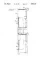
- FIG. 1is an isometric view of an expanded register rack assembly according to the invention
- FIG. 2is a section of the expanded register rack assembly taken along line 2--2 of FIG. 1 illustrating an extender board according to the invention.
- FIG. 3is a block diagram of the circuit contained on the extender board of FIG. 2.
- the electronic module 8includes a circuit board housing 10 which houses a circuit board 12 having a flange 14.
- the flange 14includes conductive traces 16 which connect with various electrical components mounted on the circuit board 12, as is well known in the art.
- the electronic module 8can be any of various modules to perform various functions.
- the electronic modulecan be a programmable controller module 8a, in which case it would include a processor board 12a supporting, among other components, a processor 18 and a memory 20 coupled thereto.
- the programmable controller modulecan be a SY/MAX® programmable controller sold by Square D Company, Palatine Ill.
- the processor 18executes steps of a program stored in the memory 20.
- the electronic module 8can also be an input/output (I/O) module 8b, which would be communicatively disposed between the programmable controller module 8a and various I/O devices.
- the electronic module 8can further be a communications module 8c, or any other like module used in programmable controller systems, as is well known in the art.
- the flange 14 of the circuit board 12is received by a slot 22 in a connector 24 of an expanded register rack assembly 28.
- the expanded register rack assembly 28includes upper and lower register racks 32, 34, respectively, which have a common rear wall, or back plane, 36.
- the back plane 36supports the slots 22 of both the upper and the lower register racks 32, 34.
- the upper register rack 32includes first through ninth upper connectors 24a-24i defining respective first through ninth upper module positions 25a-25i.
- the lower register rack assembly 34includes first through ninth lower connectors 24j-24r defining respective first through ninth lower module positions 25j-25r.
- Each of the connectors 24a-24rincludes respective first through eighteenth slots 22a-22r.
- a common channel housing 38defines a common channel which extends along the left side (as viewed in FIG. 1) of the upper and lower register racks 32, 34.
- the common channel housing 38houses an extender board 40, discussed below.
- the programmable controller module 8ais placed in the first upper module position 25a by placing the flange 14 of its processor board 12a into the first slot 22a.
- the remaining second through ninth upper module positions 25b-25i and first through ninth lower module positions 24j-24rare available for receiving the other ones of the electronic modules 8, such as the I/O modules 8b or the communication modules 8c described above.
- Upper and lower power supplies 42, 43provide power to the modules mounted in the upper and lower register racks 32, 34, respectively.
- the upper register rack 32 and the lower register rack 34each include respective upper and lower power supplies 41, 42 which provide power to the various elements of the respective register racks 32, 34.
- the power supplies 41, 42can be, for example, Type PS-31, also sold by Square D Company.
- Each of the upper and lower power supplies 41, 42includes a battery 43 for providing backup power, such as to maintain the memory and to provide for an orderly system shutdown, in event of a failure of the respective power supplies 41, 42.
- Each of the power supplies 41, 42generates a BLOW (Battery LOW) signal and an ACFAIL (AC FAILure) signal.
- the BLOW signalis a normally low digital signal which changes to a high level when the battery voltage drops below a predetermined level.
- the ACFAIL signalis a normally high digital signal which changes to a low level when the respective power supply, 41 or 42, is unable to provide adequate power, such as upon a loss of AC supply power.
- the extender board 40 mounted in the common channel 38is illustrated in FIG. 2.
- the extender board 40has upper and lower flanges 44a, b, each having conductive circuit traces 46 at respective upper and lower ends 48a, b.
- the upper end 48ais located in the channel housing 38 on the upper register rack 32.
- the lower end 48bis located in the channel housing 38 in the lower register rack 34.
- the extender board 40permits the programmable controller module 8a mounted in the first module position 25a of the upper register rack 32 to communicate with each of the electronic modules 8 mounted in the lower register rack 34.
- the upper flange 46ais received in an upper connector 50.
- the lower end 44bhas a lower end flange 52 received in a lower connector 56.
- the programmable controller module 8amonitor the status of both of the power supplies 60. Specifically, it is not just important to know whether either of the power supplies 41, 42 has failed, but rather it is necessary to know which of the power supplies 41, 42 has failed.
- the programmable controller modulewas unable to monitor the status of remote power supplies, including the condition of their respective backup batteries.
- the extender board 40permits the programmable controller module 8a mounted in the upper register rack 32 to monitor the status of the second power supply 42, including its battery.
- the extender board 40is illustrated in FIG. 3.
- the upper flange 44aincludes eighty-two conductive traces 46 which are each coupled by the extender board 40 to a respective eighty-two conductive traces 46 on the lower flange 44b.
- the extender board 40permits transmission of address, data and control signals between the upper and lower register rack assemblies.
- the extender board 40includes a first OR gate 66 having first and second input terminals 66a, b and an output terminal 66c.
- the BLOW signal from the upper power supply 41is input to the first input terminal 66a of the first OR gate 66, and the BLOW signal from the lower power supply 42 is input to the second input terminal 66b of the first OR gate 66.
- each of the BLOW signalsis low. Therefore the voltage at the output terminal 66c of the first OR gate is low.
- the programmable controller module 8amonitors the voltage at the first OR gate output terminal 66c, and activates an alarm (not shown) upon detection of a high voltage.
- the programmable controller module 8aalso monitors the power provided by each of the power supplies 41, 42. As indicated above, each of the power supplies 41, 42 generates a respective ACFAIL signal upon detection of a power supply failure. However as also indicated above, it is important for the programmable controller module 8a to specifically identify which of the power supplies 41, 42 is experiencing the failure.
- the SY/MAX® programmable controller module 8aincludes a single input terminal for directly monitoring a single ACFAIL signal. Because the programmable controller module 8a must know which of the power supplies 41, 42 failed, the two ACFAIL signals cannot simply be OR'd together. Accordingly, the upper power supply 41 ACFAIL signal is input directly into the ACFAIL input terminal of the programmable controller module 8a.
- the extender board 40includes a second OR gate 70 to permit the programmable controller module 8a to monitor the ACFAIL signal generated by lower power supply 42.
- the ACFAIL signal generated by the lower power supply 42is input into a first input terminal 70a of the second OR gate 70.
- a CLR signalis input into a second input terminal 70b of the second OR gate 70.
- An output of the second OR gate 70is joined with a lower rack module error signal.
- the CLR signalis normally low, and the ACFAIL signal is normally high. Therefore the output of the second OR gate 70 is normally high.
- the programmable controllerresponds to the low error signal by setting the CLR signal high. This results in the output of the second OR gate 70 going high and, therefore the error signal going high.
- the programmable controller module 8aresponds to the low error signal by polling each of the modules 8 in the lower register rack 34 for an error. Since none of them have an error, the programmable controller module 8a is programmed to conclude that the low error signal was caused by an ACFAIL signal generated by the lower power supply 42.
- an expanded register rackhas been provided which permits expansion of standard sized register racks. Slots in the register racks are not required to permit communication between the register racks.
- a programmable controller module mounted in one of the standard register rackscan monitor the condition of a power supply, including its battery, providing power to another of the register racks.
Landscapes
- Engineering & Computer Science (AREA)
- Automation & Control Theory (AREA)
- Microelectronics & Electronic Packaging (AREA)
- General Engineering & Computer Science (AREA)
- Physics & Mathematics (AREA)
- General Physics & Mathematics (AREA)
- Theoretical Computer Science (AREA)
- Computer Networks & Wireless Communication (AREA)
- Computer Hardware Design (AREA)
- Programmable Controllers (AREA)
Abstract
Description
1. Technical Field
The invention relates to a programmable logic controller system and, more particularly, to an expanded register rack for a programmable logic controller system which permits use of additional input/output boards and other related devices.
2. Background Prior Art
Processor based devices such as programmable logic controllers, or PLC's, typically are mounted in a register rack assembly which is placed in an electrical housing cabinet. Typically the electrical cabinets are any one of a group of standard dimensions, so the register rack assemblies are also typically made in various respectively corresponding standard dimensions.
The register rack assemblies each typically includes a backplane which contains a plurality of slots, the specific number of which depends on the particular rack dimension.
A programmable controller module comprising a processor board supporting a processor and a memory is received by one of the slots. The processor executes sequential steps of a program stored in the memory.
An input/output, or I/O, module can be received by each of the other remaining slots. Each of the I/O modules can be coupled to many input and output devices. Depending on the total number of input and output devices being monitored and controlled, respectively, many I/O modules can be required.
Because a register rack assembly is of a standard dimension, there is a limitation to the number of I/O modules which can be received by any particular register rack assembly. For example a standard nine-slot register rack assembly can accept one programmable controller module and up to eight I/O modules. If additional I/O modules are required, a second register rack assembly must be utilized. However, in order to couple the two register rack assemblies together, a serial communication board or a bus driver board would have to be placed in one of the slots of both the first and the second register rack assemblies. Accordingly only seven of the nine slots would be available for I/O modules in the first register rack assembly, and only eight of the nine slots would be available for I/O modules in the second register rack assembly.
In addition, the various modules require power supplied by a power supply. The power supply receives its primary source of power from an AC line. In addition, the power supply typically also includes a battery backup for use in the event of a failure of the AC line power or of the power supply itself.
Depending on the power consumption of the modules, often each register rack assembly of a coupled register rack assembly requires its own separate power supply. This arrangement presents a problem because the processor module in the first register rack assembly is unable to monitor the condition of the power supply, including its battery backup, providing power to the second register rack assembly. Thus, a failure of the second register rack assembly power supply would not be detected by the programmable controller module.
The present invention is provided to solve these and other problems.
It is an object of the invention to provide an expanded register rack assembly for a programmable controller system.
In accordance with the invention, the expanded register rack assembly comprises a first register rack having a first back plane. The first back plane includes a first plurality of slots adapted for receiving a first plurality of printed circuit boards housed within a first plurality of electronic modules. One of the first plurality of electronic modules comprises a programmable controller module including a processor and a memory. The processor executes sequential program steps stored in the memory. The others of the first plurality of electronic modules can be input/output modules, communications modules, or the like.
The expanded register rack assembly further includes a second register rack having a second back plane. The second back plane includes a second plurality of slots adapted for receiving a second plurality of printed circuit boards housed within a second plurality of electronic modules. The second plurality of electronic modules can be input/output modules, communications modules, or the like.
In addition, the expanded register rack assembly includes an extender board for communicatively coupling the electronic modules housed in the first and the second register racks. The extender board permits the programmable controller module to selectively access any of the other of the plurality of electronic modules received in the first and second plurality of slots.
It is comprehended that the expanded register rack assembly includes a first power supply for providing power to each of the first plurality of electronic modules. The first power supply includes a first battery for providing backup power to the first register rack in the event of failure of the first power supply.
The expanded register rack assembly further includes a second power supply for providing power to each of the second plurality of electronic modules. The second power supply includes a second battery for providing power to the second register rack assembly in the event of failure of the second power supply.
The expanded register rack assembly still further includes means for detecting a failure of either of the first and second power supplies, and means responsive to the detecting means for providing an indication of the detected failure.
Other features and advantages of the invention will be apparent from the following specification taken in conjunction with the following drawings.
FIG. 1 is an isometric view of an expanded register rack assembly according to the invention;
FIG. 2 is a section of the expanded register rack assembly taken along line 2--2 of FIG. 1 illustrating an extender board according to the invention; and
FIG. 3 is a block diagram of the circuit contained on the extender board of FIG. 2.
While this invention is susceptible of embodiments in many different forms, there is shown in the drawings and will herein be described in detail, a preferred embodiment of the invention with the understanding that the present disclosure is to be considered as an exemplification of the principles of the invention and is not intended to limit the broad aspects of the invention to the embodiment illustrated.
An electronic module 8 is illustrated in FIG. 1. The electronic module 8 includes acircuit board housing 10 which houses acircuit board 12 having aflange 14.
Theflange 14 includesconductive traces 16 which connect with various electrical components mounted on thecircuit board 12, as is well known in the art.
As will be discussed in greater detail below, the electronic module 8 can be any of various modules to perform various functions. For example, the electronic module can be a programmable controller module 8a, in which case it would include a processor board 12a supporting, among other components, aprocessor 18 and amemory 20 coupled thereto. The programmable controller module can be a SY/MAX® programmable controller sold by Square D Company, Palatine Ill. As is well known in the art, theprocessor 18 executes steps of a program stored in thememory 20.
The electronic module 8 can also be an input/output (I/O) module 8b, which would be communicatively disposed between the programmable controller module 8a and various I/O devices. The electronic module 8 can further be a communications module 8c, or any other like module used in programmable controller systems, as is well known in the art.
As discussed in greater detail below, theflange 14 of thecircuit board 12 is received by a slot 22 in aconnector 24 of an expandedregister rack assembly 28.
The expandedregister rack assembly 28 includes upper and lower register racks 32, 34, respectively, which have a common rear wall, or back plane, 36. Theback plane 36 supports the slots 22 of both the upper and the lower register racks 32, 34.
Theupper register rack 32 includes first through ninth upper connectors 24a-24i defining respective first through ninthupper module positions 25a-25i. The lowerregister rack assembly 34 includes first through ninth lower connectors 24j-24r defining respective first through ninth lower module positions 25j-25r. Each of the connectors 24a-24r includes respective first througheighteenth slots 22a-22r.
Acommon channel housing 38 defines a common channel which extends along the left side (as viewed in FIG. 1) of the upper and lower register racks 32, 34. Thecommon channel housing 38 houses anextender board 40, discussed below.
The programmable controller module 8a is placed in the firstupper module position 25a by placing theflange 14 of its processor board 12a into thefirst slot 22a.
The remaining second through ninth upper module positions 25b-25i and first through ninth lower module positions 24j-24r are available for receiving the other ones of the electronic modules 8, such as the I/O modules 8b or the communication modules 8c described above.
The physical mounting of the various electronic modules 8 in the register racks 32, 34 is explained in greater detail in commonly assigned, patents to Russell et. al., (U.S. Pat. No. 4,956,750 issued 9/11/90 to Russell, (U.S. Pat. No. 4,985,803), the specifications of which are each expressly incorporated by reference.
Upper andlower power supplies
Theupper register rack 32 and thelower register rack 34 each include respective upper andlower power supplies
Each of the upper andlower power supplies battery 43 for providing backup power, such as to maintain the memory and to provide for an orderly system shutdown, in event of a failure of therespective power supplies
Each of the power supplies 41, 42 generates a BLOW (Battery LOW) signal and an ACFAIL (AC FAILure) signal.
The BLOW signal is a normally low digital signal which changes to a high level when the battery voltage drops below a predetermined level.
The ACFAIL signal is a normally high digital signal which changes to a low level when the respective power supply, 41 or 42, is unable to provide adequate power, such as upon a loss of AC supply power.
Of course, other signal formats could be used without departing from the scope of the invention.
While it is possible to have a single power supply provide power to both the upper and thelower racks
Theextender board 40 mounted in thecommon channel 38 is illustrated in FIG. 2.
Theextender board 40 has upper and lower flanges 44a, b, each having conductive circuit traces 46 at respective upper and lower ends 48a, b. The upper end 48a is located in thechannel housing 38 on theupper register rack 32. The lower end 48b is located in thechannel housing 38 in thelower register rack 34. Theextender board 40 permits the programmable controller module 8a mounted in thefirst module position 25a of theupper register rack 32 to communicate with each of the electronic modules 8 mounted in thelower register rack 34.
The upper flange 46a is received in anupper connector 50. Thelower end 44b has a lower end flange 52 received in alower connector 56.
When the twopower supplies
As described above, in prior art systems utilizing a programmable controller module operating on I/O modules located in a plurality of register racks, the programmable controller module was unable to monitor the status of remote power supplies, including the condition of their respective backup batteries. Theextender board 40 permits the programmable controller module 8a mounted in theupper register rack 32 to monitor the status of thesecond power supply 42, including its battery.
Theextender board 40 is illustrated in FIG. 3.
The upper flange 44a includes eighty-twoconductive traces 46 which are each coupled by theextender board 40 to a respective eighty-twoconductive traces 46 on thelower flange 44b. Theextender board 40 permits transmission of address, data and control signals between the upper and lower register rack assemblies.
Theextender board 40 includes a first ORgate 66 having first and second input terminals 66a, b and anoutput terminal 66c. The BLOW signal from theupper power supply 41 is input to the first input terminal 66a of the first ORgate 66, and the BLOW signal from thelower power supply 42 is input to thesecond input terminal 66b of the first ORgate 66.
In normal operation with good batteries in each of the power supplies 41, 42, each of the BLOW signals is low. Therefore the voltage at theoutput terminal 66c of the first OR gate is low.
When one of the power supplies 41, 42 detects a low battery condition, its respective BLOW signal will go high, causing the voltage at theoutput terminal 66c of the first ORgate 66 to go high.
The programmable controller module 8a monitors the voltage at the first ORgate output terminal 66c, and activates an alarm (not shown) upon detection of a high voltage.
The programmable controller module 8a also monitors the power provided by each of the power supplies 41, 42. As indicated above, each of the power supplies 41, 42 generates a respective ACFAIL signal upon detection of a power supply failure. However as also indicated above, it is important for the programmable controller module 8a to specifically identify which of the power supplies 41, 42 is experiencing the failure.
The SY/MAX® programmable controller module 8a includes a single input terminal for directly monitoring a single ACFAIL signal. Because the programmable controller module 8a must know which of the power supplies 41, 42 failed, the two ACFAIL signals cannot simply be OR'd together. Accordingly, theupper power supply 41 ACFAIL signal is input directly into the ACFAIL input terminal of the programmable controller module 8a.
Theextender board 40 includes a second ORgate 70 to permit the programmable controller module 8a to monitor the ACFAIL signal generated bylower power supply 42. The ACFAIL signal generated by thelower power supply 42 is input into a first input terminal 70a of the second ORgate 70. A CLR signal is input into asecond input terminal 70b of the second ORgate 70. An output of the second ORgate 70 is joined with a lower rack module error signal.
The CLR signal is normally low, and the ACFAIL signal is normally high. Therefore the output of the second ORgate 70 is normally high.
Upon detection of a failure in thelower power supply 42, its ACFAIL signal goes low, causing the output of the second ORgate 70 to go low, causing the error signal to go low.
The programmable controller responds to the low error signal by setting the CLR signal high. This results in the output of the second ORgate 70 going high and, therefore the error signal going high.
In addition, the programmable controller module 8a responds to the low error signal by polling each of the modules 8 in thelower register rack 34 for an error. Since none of them have an error, the programmable controller module 8a is programmed to conclude that the low error signal was caused by an ACFAIL signal generated by thelower power supply 42.
Thus it can be seen that an expanded register rack has been provided which permits expansion of standard sized register racks. Slots in the register racks are not required to permit communication between the register racks. A programmable controller module mounted in one of the standard register racks can monitor the condition of a power supply, including its battery, providing power to another of the register racks.
It will be understood that the invention may be embodied in other specific forms without departing from the spirit or central characteristics thereof. The present examples and embodiments, therefore, are to be considered in all respects as illustrative and not restrictive, and the invention is not to be limited to the details given herein.
Claims (2)
1.
An expanded board register rack assembly for a programmable controller system comprising;
a first standard sized register rack including a first plurality of slots adapted for receiving a first plurality of circuit boards housed within a first plurality of electronic modules, a first one of said first plurality of electronic modules being a programmable controller module which includes a processor and a memory, the processor for executing sequential program steps stored in said memory,
a first power supply;
a second standard sized register rack connected in a vertical juxtaposition to said first register rack, including a second plurality of circuit boards housed within a second plurality of electronic modules,
a second power supply; and
an extender board means for communicatively coupling said first and said second standard sized registered racks, said communicatively coupled means permitting said programmable controller module to selectively access any of said other electronic modules received in said first and second plurality of slots, wherein:
said a first power supply is adapted for coupling to AC line power, said first power supply for providing power to each of said first plurality of electronic modules, said first power supply including a first battery for providing power in event of failure of said AC line power; and
said a second power supply adapted for coupling to AC line power, said second power supply for providing power to each of said second plurality of electronic modules, said second power supply including a second battery for providing power in event of failure of said AC line power, and further including:
means electrically connected to said first and second power supplies for detecting a failure of either of said first and second power supplies; said detecting means generating a signal to identify which of said first or second power supply experienced the failure, and
means responsive to said signal from the detecting means for providing an indication of said detected failure to said programmable controller module.
2. An expanded board register rack assembly for a programmable controller system comprising:
a first standard sized register rack including a first plurality of slots adapted for receiving a first plurality of circuit boards housed within a first plurality of electronic modules, a first one of said first plurality of electronic modules being a programmable controller module which includes a processor and a memory, the processor for executing sequential program steps stored in said memory,
a first power supply;
a second standard sized register rack connected in a vertical juxtaposition to said first register rack, including a second plurality of circuit boards housed within a second plurality of electronic modules,
a second power supply; and
an extender board means for communicatively coupling said first and said second standard sized registered racks, said communicatively coupling means permitting said programmable controller module to selectively access any of said other electronic modules received in said first and second plurality of slots, wherein:
said first power supply adapted for coupling to AC line power, said first power supply for providing power to each of said electronic modules received in said plurality of module positions, said first power supply including a first battery for providing power in event of failure of said AC line power;
said second power supply adapted for coupling to AC line power, said second power supply for providing power to each of said electronic modules received in said plurality of module positions, said second power supply including a second battery for providing power in event of failure of said AC line power, and further including:
means connected to said communicating coupling means for detecting a failure of either of said first and second power supplies, said means generating a signal to identify which of said first or second power supply experienced the failure; and
means responsive to said generating signal of the detecting means for providing an indication of said detected failure to said programmable controller module.
Priority Applications (1)
| Application Number | Priority Date | Filing Date | Title |
|---|---|---|---|
| US07/322,834US5065141A (en) | 1989-03-13 | 1989-03-13 | Expanded register rack for a programmable logic controller |
Applications Claiming Priority (1)
| Application Number | Priority Date | Filing Date | Title |
|---|---|---|---|
| US07/322,834US5065141A (en) | 1989-03-13 | 1989-03-13 | Expanded register rack for a programmable logic controller |
Publications (1)
| Publication Number | Publication Date |
|---|---|
| US5065141Atrue US5065141A (en) | 1991-11-12 |
Family
ID=23256638
Family Applications (1)
| Application Number | Title | Priority Date | Filing Date |
|---|---|---|---|
| US07/322,834Expired - LifetimeUS5065141A (en) | 1989-03-13 | 1989-03-13 | Expanded register rack for a programmable logic controller |
Country Status (1)
| Country | Link |
|---|---|
| US (1) | US5065141A (en) |
Cited By (31)
| Publication number | Priority date | Publication date | Assignee | Title |
|---|---|---|---|---|
| US5157590A (en)* | 1991-04-19 | 1992-10-20 | Square D Company | Mounting bracket for a programmable logic controller control module |
| US5159534A (en)* | 1991-01-22 | 1992-10-27 | Johnson Service Company | Electronic/electromechanical packaging arrangement for facility management system |
| US5191970A (en)* | 1991-09-27 | 1993-03-09 | At&T Bell Laboratories | Apparatus for equipment unit protection switching |
| US5251109A (en)* | 1990-03-20 | 1993-10-05 | Siemens Nixdorf Informationssysteme Ag | Holding device for plug-in cards |
| US5373133A (en)* | 1991-09-27 | 1994-12-13 | At&T Corp. | Equipment unit latch and associated switch |
| WO1995024729A3 (en)* | 1994-03-11 | 1996-05-02 | Panda Project | Modular architecture for high bandwidth computers |
| US5613164A (en)* | 1995-03-22 | 1997-03-18 | International Business Machines Corporation | Portable system having data distribution and power distribution removably positioned within portable enclosure during shipping and adapted for repositioning within internal storage space during operation |
| US6092139A (en)* | 1994-03-11 | 2000-07-18 | Crane, Jr.; Stanford W. | Passive backplane capable of being configured to a variable data path width corresponding to a data size of the pluggable CPU board |
| US6121695A (en)* | 1995-10-11 | 2000-09-19 | Invetech Operations Pty. Ltd. | Modular power supply |
| US6131274A (en)* | 1999-07-01 | 2000-10-17 | 3Com Corporation | Apparatus and method for guiding a circuit board into an electronic chassis |
| US6147877A (en)* | 1996-04-23 | 2000-11-14 | Asea Brown Boveri Ab | Device for transferring electric signals |
| US6239984B1 (en)* | 1999-08-12 | 2001-05-29 | 3Com Corporation | Backplane circuit board for an electronic chassis |
| US6359786B1 (en)* | 1998-06-01 | 2002-03-19 | James S. Bianco | Communication terminal with multiconfigurable function modules |
| US6421911B1 (en)* | 1999-11-30 | 2002-07-23 | 3Com Corporation | Apparatus and method for providing automatic alignment of a circuit board within a chassis |
| WO2003030606A1 (en)* | 2001-10-04 | 2003-04-10 | Avici Systems, Inc. | Rack mounted routers |
| USD477813S1 (en) | 2002-02-13 | 2003-07-29 | Schneider Automation, Inc. | Programmable controller housing |
| USD477814S1 (en) | 2002-02-13 | 2003-07-29 | Schneider Automation, Inc. | Programmable controller housing |
| USD478322S1 (en) | 2002-02-13 | 2003-08-12 | Schneider Automation, Inc. | Programmable controller housing |
| USD478873S1 (en) | 2002-02-13 | 2003-08-26 | Schneider Automation, Inc. | Programmable controller housing |
| USD480055S1 (en) | 2002-02-13 | 2003-09-30 | Schneider Automation, Inc. | Programmable controller housing |
| USD480368S1 (en) | 2002-02-13 | 2003-10-07 | Schneider Automation, Inc. | Programmable controller housing |
| USD480369S1 (en) | 2002-02-13 | 2003-10-07 | Schneider Automation, Inc. | Programmable controller housing |
| USD480367S1 (en) | 2002-02-13 | 2003-10-07 | Schneider Automation, Inc. | Programmable controller housing |
| USD481014S1 (en) | 2002-02-13 | 2003-10-21 | Schneider Automation, Inc. | Programmable controller housing |
| USD482005S1 (en) | 2002-02-13 | 2003-11-11 | Schneider Automation, Inc. | Programmable controller housing |
| US6741466B1 (en)* | 2002-07-18 | 2004-05-25 | Rockwell Collins | Modular electronics system chassis |
| US20050068716A1 (en)* | 2002-06-28 | 2005-03-31 | Pereira Robert A. | Modular power distribution system for use in computer equipment racks |
| EP1704839A1 (en)* | 1996-08-29 | 2006-09-27 | Bausch & Lomb Surgical, Inc. | Surgical module with neuron chip communication |
| USD743350S1 (en)* | 2011-12-16 | 2015-11-17 | Siemens Aktiengesellschaft | Periphery data processing device |
| JP2019071049A (en)* | 2017-10-02 | 2019-05-09 | フィッシャー−ローズマウント システムズ,インコーポレイテッド | In-place retrofit of plc control systems |
| CN112616247A (en)* | 2020-12-17 | 2021-04-06 | 上海海得控制系统股份有限公司 | PLC fixed baseplate and PLC system |
Citations (3)
| Publication number | Priority date | Publication date | Assignee | Title |
|---|---|---|---|---|
| US4151580A (en)* | 1977-11-21 | 1979-04-24 | Allen-Bradley Company | Circuit board assembly with disconnect arm |
| US4675539A (en)* | 1985-09-17 | 1987-06-23 | Codex Corporation | Backup power system |
| US4675538A (en)* | 1986-06-02 | 1987-06-23 | Epstein Barry M | General purpose uninterruptible power supply |
- 1989
- 1989-03-13USUS07/322,834patent/US5065141A/ennot_activeExpired - Lifetime
Patent Citations (3)
| Publication number | Priority date | Publication date | Assignee | Title |
|---|---|---|---|---|
| US4151580A (en)* | 1977-11-21 | 1979-04-24 | Allen-Bradley Company | Circuit board assembly with disconnect arm |
| US4675539A (en)* | 1985-09-17 | 1987-06-23 | Codex Corporation | Backup power system |
| US4675538A (en)* | 1986-06-02 | 1987-06-23 | Epstein Barry M | General purpose uninterruptible power supply |
Cited By (48)
| Publication number | Priority date | Publication date | Assignee | Title |
|---|---|---|---|---|
| US5251109A (en)* | 1990-03-20 | 1993-10-05 | Siemens Nixdorf Informationssysteme Ag | Holding device for plug-in cards |
| US5159534A (en)* | 1991-01-22 | 1992-10-27 | Johnson Service Company | Electronic/electromechanical packaging arrangement for facility management system |
| US5157590A (en)* | 1991-04-19 | 1992-10-20 | Square D Company | Mounting bracket for a programmable logic controller control module |
| US5191970A (en)* | 1991-09-27 | 1993-03-09 | At&T Bell Laboratories | Apparatus for equipment unit protection switching |
| US5373133A (en)* | 1991-09-27 | 1994-12-13 | At&T Corp. | Equipment unit latch and associated switch |
| US6092139A (en)* | 1994-03-11 | 2000-07-18 | Crane, Jr.; Stanford W. | Passive backplane capable of being configured to a variable data path width corresponding to a data size of the pluggable CPU board |
| WO1995024729A3 (en)* | 1994-03-11 | 1996-05-02 | Panda Project | Modular architecture for high bandwidth computers |
| US5812797A (en)* | 1994-03-11 | 1998-09-22 | The Panda Project | Computer having a high density connector system |
| US5822551A (en)* | 1994-03-11 | 1998-10-13 | The Panda Project | Passive backplane capable of being configured to a variable data path width corresponding to a data size of the pluggable CPU board |
| US6073229A (en)* | 1994-03-11 | 2000-06-06 | The Panda Project | Computer system having a modular architecture |
| US20040010638A1 (en)* | 1994-03-11 | 2004-01-15 | Silicon Bandwidth, Inc. | Modular architecture for high bandwidth computers |
| US7103753B2 (en) | 1994-03-11 | 2006-09-05 | Silicon Bandwith Inc. | Backplane system having high-density electrical connectors |
| US6574726B2 (en) | 1994-03-11 | 2003-06-03 | Silicon Bandwidth, Inc. | Modular architecture for high bandwidth computers |
| US7803020B2 (en) | 1994-03-11 | 2010-09-28 | Crane Jr Stanford W | Backplane system having high-density electrical connectors |
| US20100323536A1 (en)* | 1994-03-11 | 2010-12-23 | Wolpass Capital Inv., L.L.C. | Backplane system having high-density electrical connectors |
| US5613164A (en)* | 1995-03-22 | 1997-03-18 | International Business Machines Corporation | Portable system having data distribution and power distribution removably positioned within portable enclosure during shipping and adapted for repositioning within internal storage space during operation |
| US6121695A (en)* | 1995-10-11 | 2000-09-19 | Invetech Operations Pty. Ltd. | Modular power supply |
| US6147877A (en)* | 1996-04-23 | 2000-11-14 | Asea Brown Boveri Ab | Device for transferring electric signals |
| EP1704839A1 (en)* | 1996-08-29 | 2006-09-27 | Bausch & Lomb Surgical, Inc. | Surgical module with neuron chip communication |
| US6359786B1 (en)* | 1998-06-01 | 2002-03-19 | James S. Bianco | Communication terminal with multiconfigurable function modules |
| US6131274A (en)* | 1999-07-01 | 2000-10-17 | 3Com Corporation | Apparatus and method for guiding a circuit board into an electronic chassis |
| US6239984B1 (en)* | 1999-08-12 | 2001-05-29 | 3Com Corporation | Backplane circuit board for an electronic chassis |
| US6421911B1 (en)* | 1999-11-30 | 2002-07-23 | 3Com Corporation | Apparatus and method for providing automatic alignment of a circuit board within a chassis |
| WO2003030606A1 (en)* | 2001-10-04 | 2003-04-10 | Avici Systems, Inc. | Rack mounted routers |
| USD481014S1 (en) | 2002-02-13 | 2003-10-21 | Schneider Automation, Inc. | Programmable controller housing |
| USD478873S1 (en) | 2002-02-13 | 2003-08-26 | Schneider Automation, Inc. | Programmable controller housing |
| USD480367S1 (en) | 2002-02-13 | 2003-10-07 | Schneider Automation, Inc. | Programmable controller housing |
| USD478322S1 (en) | 2002-02-13 | 2003-08-12 | Schneider Automation, Inc. | Programmable controller housing |
| USD482005S1 (en) | 2002-02-13 | 2003-11-11 | Schneider Automation, Inc. | Programmable controller housing |
| USD477814S1 (en) | 2002-02-13 | 2003-07-29 | Schneider Automation, Inc. | Programmable controller housing |
| USD480369S1 (en) | 2002-02-13 | 2003-10-07 | Schneider Automation, Inc. | Programmable controller housing |
| USD477813S1 (en) | 2002-02-13 | 2003-07-29 | Schneider Automation, Inc. | Programmable controller housing |
| USD480368S1 (en) | 2002-02-13 | 2003-10-07 | Schneider Automation, Inc. | Programmable controller housing |
| USD480055S1 (en) | 2002-02-13 | 2003-09-30 | Schneider Automation, Inc. | Programmable controller housing |
| US20050068716A1 (en)* | 2002-06-28 | 2005-03-31 | Pereira Robert A. | Modular power distribution system for use in computer equipment racks |
| US7215535B2 (en)* | 2002-06-28 | 2007-05-08 | Hewlett-Packard Development Company, L.P. | Modular power distribution system for use in computer equipment racks |
| US6741466B1 (en)* | 2002-07-18 | 2004-05-25 | Rockwell Collins | Modular electronics system chassis |
| USD743350S1 (en)* | 2011-12-16 | 2015-11-17 | Siemens Aktiengesellschaft | Periphery data processing device |
| USD743351S1 (en)* | 2011-12-16 | 2015-11-17 | Siemens Aktiengesellschaft | Point-to-point communication processor (PtP-CP) |
| USD743913S1 (en)* | 2011-12-16 | 2015-11-24 | Siemens Aktiengesellschaft | Connector device for a programmable logic controller |
| USD745471S1 (en)* | 2011-12-16 | 2015-12-15 | Siemens Aktiengesellschaft | Periphery data processing device |
| USD745470S1 (en)* | 2011-12-16 | 2015-12-15 | Siemens Aktiengesellschaft | Periphery front plug |
| USD766191S1 (en)* | 2011-12-16 | 2016-09-13 | Siemens Aktiengesellschaft | Power supply feed in plug |
| USD766839S1 (en)* | 2011-12-16 | 2016-09-20 | Siemens Aktiengesellschaft | Module rack |
| JP2019071049A (en)* | 2017-10-02 | 2019-05-09 | フィッシャー−ローズマウント システムズ,インコーポレイテッド | In-place retrofit of plc control systems |
| US12089361B2 (en) | 2017-10-02 | 2024-09-10 | Fisher-Rosemount Systems, Inc. | In-place retrofit of PLC control systems |
| JP7738380B2 (en) | 2017-10-02 | 2025-09-12 | フィッシャー-ローズマウント システムズ,インコーポレイテッド | In-place retrofit of PLC control systems |
| CN112616247A (en)* | 2020-12-17 | 2021-04-06 | 上海海得控制系统股份有限公司 | PLC fixed baseplate and PLC system |
Similar Documents
| Publication | Publication Date | Title |
|---|---|---|
| US5065141A (en) | Expanded register rack for a programmable logic controller | |
| US6275881B1 (en) | Device for inherently safe signal matching | |
| EP0843260B1 (en) | Automatic shelf-address assignment for shelves containing disk drives and error detection method and apparatus | |
| US5541810A (en) | Expandable programmable controller | |
| US5119498A (en) | Feature board with automatic adjustment to one of two bus widths based on sensing power level at one connection contact | |
| US4179172A (en) | Modular hardware packaging apparatus | |
| US5327435A (en) | Method for testing a processor module in a computer system | |
| EP0204507B1 (en) | System configuration tracing method and apparatus | |
| US6700477B2 (en) | Signal-transmission device | |
| US4774656A (en) | Method and apparatus for protecting and monitoring the transmission of information between the central unit of a programmable controller and the sensors and/or the actuators of the controlled process | |
| US7444208B2 (en) | Electrical system wiring diagram generating system, and power supply device and program used for the same | |
| US5455911A (en) | Communications protocol for use in transferring data over a serial bus | |
| WO2014204441A1 (en) | Automatic transfer switch module | |
| US4864531A (en) | Error control apparatus using restore memory for recovering from parity discordances in transmissions between controller and real-time I/O devices | |
| US20030079062A1 (en) | Method and apparatus for sensing positions of device enclosures within multi-shelf cabinets | |
| US6163854A (en) | Switchgear cabinet monitoring installation | |
| Cisco | FastPADmpr 12/24 Hardware | |
| Cisco | FastPADmpr 12/24 Hardware | |
| Cisco | FastPADmpr 12/24 Hardware | |
| Cisco | FastPADmpr12/24 Hardware | |
| Cisco | FastPADmpr 12/24 Hardware | |
| Cisco | FastPADmpr 12/24 Hardware | |
| Cisco | FastPADmpr 12/24 Hardware | |
| CN100523841C (en) | Connection fault inspection between plates and socket structure forsingle plate and rear plate | |
| EP0503967B1 (en) | High density modular power switch drivers |
Legal Events
| Date | Code | Title | Description |
|---|---|---|---|
| AS | Assignment | Owner name:SQUARE D COMPANY, ILLINOIS Free format text:ASSIGNMENT OF ASSIGNORS INTEREST.;ASSIGNOR:WHITSITT, STEVEN L.;REEL/FRAME:005053/0960 Effective date:19890308 | |
| STCF | Information on status: patent grant | Free format text:PATENTED CASE | |
| AS | Assignment | Owner name:MODICON, INC., MASSACHUSETTS Free format text:ASSIGNMENT OF ASSIGNORS INTEREST;ASSIGNOR:SQUARE D COMPANY;REEL/FRAME:007235/0131 Effective date:19941014 | |
| AS | Assignment | Owner name:AEG SCHNEIDER AUTOMATION, INC. Free format text:CHANGE OF NAME;ASSIGNOR:MODICON, INC.;REEL/FRAME:007397/0801 Effective date:19941014 | |
| FPAY | Fee payment | Year of fee payment:4 | |
| AS | Assignment | Owner name:SCHNEIDER AUTOMATION INC., MASSACHUSETTS Free format text:CHANGE OF NAME;ASSIGNOR:AEG SCHNEIDER AUTOMATION, INC.;REEL/FRAME:008855/0799 Effective date:19960801 | |
| FPAY | Fee payment | Year of fee payment:8 | |
| FPAY | Fee payment | Year of fee payment:12 |