US5063669A - Razor head, especially razor blade unit, of a wet razor - Google Patents
Razor head, especially razor blade unit, of a wet razorDownload PDFInfo
- Publication number
- US5063669A US5063669AUS07/682,194US68219491AUS5063669AUS 5063669 AUS5063669 AUS 5063669AUS 68219491 AUS68219491 AUS 68219491AUS 5063669 AUS5063669 AUS 5063669A
- Authority
- US
- United States
- Prior art keywords
- razor
- razor blade
- base member
- plastic body
- head according
- Prior art date
- Legal status (The legal status is an assumption and is not a legal conclusion. Google has not performed a legal analysis and makes no representation as to the accuracy of the status listed.)
- Expired - Lifetime
Links
- 239000004033plasticSubstances0.000claimsabstractdescription32
- 125000006850spacer groupChemical group0.000claimsdescription9
- 238000004804windingMethods0.000claimsdescription3
- 238000000034methodMethods0.000description3
- 239000002991molded plasticSubstances0.000description2
- 230000001681protective effectEffects0.000description2
- 208000027418Wounds and injuryDiseases0.000description1
- 230000001154acute effectEffects0.000description1
- 238000010276constructionMethods0.000description1
- 230000006378damageEffects0.000description1
- 230000009977dual effectEffects0.000description1
- 208000014674injuryDiseases0.000description1
- 238000012986modificationMethods0.000description1
- 230000004048modificationEffects0.000description1
- 238000000465mouldingMethods0.000description1
- 238000010618wire wrapMethods0.000description1
Images


Classifications
- B—PERFORMING OPERATIONS; TRANSPORTING
- B26—HAND CUTTING TOOLS; CUTTING; SEVERING
- B26B—HAND-HELD CUTTING TOOLS NOT OTHERWISE PROVIDED FOR
- B26B21/00—Razors of the open or knife type; Safety razors or other shaving implements of the planing type; Hair-trimming devices involving a razor-blade; Equipment therefor
- B26B21/40—Details or accessories
- B26B21/4006—Blades or blade units with discontinuous cutting edges, e.g. wire-wrapped, notches
Definitions
- the present inventionrelates to a razor head, and especially a razor blade unit, that is disposed at the front end of a handle of a wet razor.
- the razor headhas a plastic body that comprises a forward guide strip and a rear cover, with a razor blade means in the form of a single or double razor blade being disposed in the plastic body.
- the razor blade meansrests upon a platform or support means of a base member of the plastic body and is fixed in place between this support means and an upper part of the plastic body that is secured to the base member.
- a razor headthat carries the single or double razor blade.
- the razor headcan be integrally formed with the handle as a molded plastic part. If the razor head is separate from the handle and is to be secured thereto in an exchangeable manner via an appropriate mechanism, it is designated as a so-called razor blade unit, with a single or double razor blade being fixedly embedded in a plastic housing.
- a plastic bodyin which a single or double razor blade is fixedly embedded.
- This plastic bodyhas a forward guide strip as well as a rear cover.
- the plastic bodyincludes a base member that at the top defines a platform or support means upon which the single or double razor blade rests.
- the razor blade meansis fixed between this base member and an upper part of the plastic body, with this upper part being the rear cover.
- the single or double razor bladeis held securely in position between the base member of the plastic body and a rear cover.
- the forward guide stripis separate from the rear cover and is part of the base member of the plastic body.
- the razor geometryis defined by the arrangement of the forward guide strip, the cutting edge or edges of the razor blade or blades, as well as the rear cover, and since with the heretofore known razor blade unit three individual components are involved that only after assembly form the razor blade unit, it is extremely difficult to achieve an optimum razor geometry due to the unavoidable deviations from the ideal positions of these three individual components.
- FIG. 1is a top view of one exemplary embodiment of the inventive razor head in the form of a razor blade unit of a wet razor;
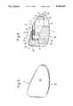
- FIG. 2is a front view of the razor blade unit of FIG. 1;
- FIG. 3is a rear view of the razor blade unit of FIG. 1;
- FIG. 4is a bottom view of the razor blade unit of FIG. 1;
- FIG. 5is an enlarged side view of the razor blade unit of FIG. 1;
- FIG. 6is an enlarged cross-sectional view taken along the line VI--VI in FIG. 1;
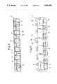
- FIG. 7is a top view of the base member of the razor blade unit without the upper part, which is formed by the forward guide strip, the rear cover, and the side walls;
- FIG. 8is a front view of the base member
- FIG. 10is a bottom view of the base member
- FIG. 11is an enlarged side view of the base member.
- the razor head of the present inventionis characterized primarily in that the guide strip at the front side of the plastic body and the cover at the back side of the plastic body are interconnected via side strips while leaving a central opening in the vicinity of the cutting edges of the razor blade means, with the thusformed, frame-like upper part being placed upon and secured to the base member.
- the razor headand in particular of the razor blade unit, is provided via this one-piece upper part, which is in the form of a molded plastic piece and is formed from the front guide strip, the rear cover, and the side strips.
- the upper partessentially from above, onto the base member and to securely connect it thereto. This can be accomplished, for example, via interlocking or in any other suitable manner.
- the thus-constructed razor headhas the advantage that the reciprocal geometric arrangement between the front guide strip on the one hand and the rear cover on the other hand is fixedly provided since these parts are formed by a one-piece component, so that reciprocal assembly deviations cannot occur.
- the frame-like upper partIn order to provide the correct geometric arrangement for the third element that codetermines the razor geometry, namely the razor blade or blades, it is merely necessary to secure the frame-like upper part in an exact manner upon the base member. However, since the frame-like upper part has a relatively large surface and in particular also has mounting points in the region of the front guide strip, it is technically readily possible to undertake this process.
- the side stripsare preferably formed by side walls of the plastic body. This represents the simplest manner for connecting the front guide strip and the rear cover via a portion of the plastic housing.
- the guide striphave a stepped longitudinal profiling.
- the single or double razor bladebe held upon the support means of the base part by being wrapped with wire, with those inner sides of the guide strip and the cover of the frame-like upper part that face the wire being provided with receiving grooves for the wire.
- This wirein the form of a protective wire, on the one hand has the advantage that it significantly improves the shaving characteristics.
- this wirehas the advantage that after the single or double razor blade is placed upon the support means of the base member, the wire holds the razor blade means securely in place and thus provides a first securement or fixation. The placement and securement of the upper part upon the base member then serves merely for the final fixation of the single or double razor blade within the plastic body.
- wire wrapping or windingmeans that either a helical winding is provided or that the wire is merely guided in a zigzagged manner back and forth over the upper side of the razor head in the vicinity of the surface that engages the skin of a user, as will be described in detail subsequently.
- a double razor bladeit is proposed pursuant to a further specific embodiment of the present invention that the two razor blades be secured to both sides of a spacer that is disposed between them, with the thus-formed razor blade/spacer/razor blade unit being inserted into the plastic body, essentially from above, onto the support means, where it is held by the wire.
- Thisprovides an extremely simple preassembly of the double razor blade in that the appropriate unit is merely placed upon the base member and is held by the wire. It is then merely necessary to place the upper part upon the base member and to secure it thereto.
- the coveris provided with a friction-reducing glide or anti-friction strip.
- This glide stripis preferably convexly curved, and pursuant to one preferred specific embodiment has a forward, essentially planar or slightly convexly curved leg as well as a rear, similarly essentially planar or slightly convexly curved leg that is disposed at an angle to the forward leg, with these two legs being interconnected via a rounded portion.
- Such a glide strip that is curved over the covercan be produced via a special hot molding process and can be applied.
- the particular advantage of such a configurationis that the glide strip is also more effective at the end of the razor head. Since the skin is made taut during shaving and is pressed in, a bulge is formed at the end of the razor head.
- the curved glide stripoptimally glides in this region, and thus increases a comfortable shave.
- the illustrated razor headwhich is in the form of a so-called razor blade unit for a wet or safety razor, and can be secured to the front end of a non-illustrated handle, comprises a plastic body 1 in which are disposed two razor blades 2, the cutting edges 3 of which extend parallel to one another and are offset one behind the other.
- the plastic body 1comprises a base member 4 that is provided with the razor blades 2, as well as an upper part 5 that is placed upon the base member 4.
- the base member 4 of the plastic body 1is provided with through slots 6 that are primarily disposed in the interior thereof.
- the base member 4defines a platform or support means 7 for the razor blades 2.
- a spacer 8is sandwiched between the two razor blades 2, which are securely connected to this spacer.
- These componentsthus form a razor blade/spacer/razor blade unit 9, which is placed from above upon the support means 7 of the base member 4.
- the spacer 8projects out to the side and is received in recesses or slots 10 in the sides of the base member 4.
- the unit 9is held via a wire or other filament 11 that extends in a zigzagged or staggered manner; the wire 11 is guided over the upper side 12 of the unit 9, and hence of the base member 4 of the plastic body 1.
- the lower portion of the front side 13 of the base member 4is provided with downwardly directed, integral projections 14 that are embodied as elongated strips.
- the width of these projections 14 as viewed in the direction of the cutting edges 3 of the razor blades 2essentially corresponds to the spacing between the projections 14.
- the projections 14are provided with an upwardly extending extension 15.
- the back side 16 of the base member 4is provided with projections 14' that are directed toward the rear. These projections 14' fill the gaps between the projections 14 of the front side 13. In a manner similar to the construction of the projections 14, the projections 14' are also provided with extensions 15', which, however, are directed downwardly. Finally, the back side 16 of the base member 4 is provided near its ends with respective integral mounting or securing projections 17.
- One end of the wire 11is first secured to one of the securing projections 17. Subsequently, the wire 11 is guided over the unit 9 toward the front and about a projection 14, whereupon it is turned by 180° to again extend toward the rear over the unit 9, where the wire 11 is guided about a pertaining projection 14'. The wire 11 is thus sequentially guided about the projections 14 and 14', whereupon the other end of the wire is finally secured to the securing projection 17 disposed at the other side of the base member 4.
- portions of the wire 11 disposed in the region of the upper side 12extend parallel to one another and essentially equidistantly from one another.
- the wire 11serves a dual function of holding the unit 9 securely in place upon the support means 7 on the base member 4, and also preventing injury to the skin.
- the upper part 5is a one-piece plastic component and is provided with a forward guide strip 18 that extends parallel to the cutting edges 3 of the razor blades 2 and is provided with a stepped longitudinal profiling 19.
- a protective cover 20is provided in the back region. This cover is provided at the top with a convexly curved glide or antifriction strip 21 having a first leg 22 and a second leg 22' that is disposed at an acute angle to the first leg 22 and is interconnected therewith via a rounded portion 23.
- the angle between the two legs 22, 22' of the glide strip 21can also be 90° or an obtuse angle.
- the two legs 22, 22' of the glide strip 21have an essentially planar or slightly convexly curved configuration.
- this glide strip 21is also more effective at the end of the razor blade unit. Since when shaving the skin is made taut and is pressed in, a bulge is formed at the end of the razor blade unit. Thus, the curved glide strip 21 glides better in this region and thus increases a comfortable shave.
- the forward guide strip 18 and the rear cover 20are interconnected by side walls 24. Disposed between these components is an opening 25 in the vicinity of the cutting edges 3 of the razor blades 2, as can be seen in particular in the top view of FIG. 1.
- Both the inner side of the guide strip 18 as well as the inner side of the cover 20are provided with receiving grooves 26 for the wire 11.
- Recesses 27are provided below the guide strip 18 that interengage in a corresponding manner with the projections 14 of the base member 4.
- the back of the upper part 5, which is formed from the guide strip 18, the cover 20 and the side walls 24,is provided with through passages 28 that correspond with appropriate through passages in the spacer 8.
- the upper part 5is placed from above upon the base member 4, which includes the unit 9 that is secured by the wire 11.
- the upper part 5is secured in place in, for example, an interlocking manner, or in any other convenient manner.
- the wire 11extends in the receiving grooves 26 provided on the inner side of the upper part 5.
- Extending the wire 11 in the vicinity of the upper side 12has the advantage that the underside 29 of the plastic body 1 remains free, so that appropriate mounting or securing systems can be provided.
Landscapes
- Life Sciences & Earth Sciences (AREA)
- Forests & Forestry (AREA)
- Engineering & Computer Science (AREA)
- Mechanical Engineering (AREA)
- Dry Shavers And Clippers (AREA)
- Knives (AREA)
Abstract
Description
The present invention relates to a razor head, and especially a razor blade unit, that is disposed at the front end of a handle of a wet razor. The razor head has a plastic body that comprises a forward guide strip and a rear cover, with a razor blade means in the form of a single or double razor blade being disposed in the plastic body. The razor blade means rests upon a platform or support means of a base member of the plastic body and is fixed in place between this support means and an upper part of the plastic body that is secured to the base member.
Various embodiments of wet or safety razors are known. In each case, disposed at the front end of a handle is a razor head that carries the single or double razor blade. The razor head can be integrally formed with the handle as a molded plastic part. If the razor head is separate from the handle and is to be secured thereto in an exchangeable manner via an appropriate mechanism, it is designated as a so-called razor blade unit, with a single or double razor blade being fixedly embedded in a plastic housing.
Various embodiments of razor heads in the form of such razor blade units are known. In each case, a plastic body is provided in which a single or double razor blade is fixedly embedded. This plastic body has a forward guide strip as well as a rear cover. The plastic body includes a base member that at the top defines a platform or support means upon which the single or double razor blade rests. The razor blade means is fixed between this base member and an upper part of the plastic body, with this upper part being the rear cover.
With such a known razor blade unit, the single or double razor blade is held securely in position between the base member of the plastic body and a rear cover. The forward guide strip is separate from the rear cover and is part of the base member of the plastic body. However, since the razor geometry is defined by the arrangement of the forward guide strip, the cutting edge or edges of the razor blade or blades, as well as the rear cover, and since with the heretofore known razor blade unit three individual components are involved that only after assembly form the razor blade unit, it is extremely difficult to achieve an optimum razor geometry due to the unavoidable deviations from the ideal positions of these three individual components.
It is therefore an object of the present invention to provide a razor head, and especially a razor blade unit, of a wet razor of the aforementioned general type whereby while affording a straightforward assembly, the reciprocal geometric coordination between the guide strip, the razor blade or blades, and the cover is improved.
This object, and other objects and advantages of the present invention, will appear more clearly from the following specification in conjunction with the accompanying schematic drawings, in which:
FIG. 1 is a top view of one exemplary embodiment of the inventive razor head in the form of a razor blade unit of a wet razor;
FIG. 2 is a front view of the razor blade unit of FIG. 1;
FIG. 3 is a rear view of the razor blade unit of FIG. 1;
FIG. 4 is a bottom view of the razor blade unit of FIG. 1;
FIG. 5 is an enlarged side view of the razor blade unit of FIG. 1;
FIG. 6 is an enlarged cross-sectional view taken along the line VI--VI in FIG. 1;
FIG. 7 is a top view of the base member of the razor blade unit without the upper part, which is formed by the forward guide strip, the rear cover, and the side walls;
FIG. 8 is a front view of the base member;
FIG. 9 is a rear view of the base member;
FIG. 10 is a bottom view of the base member; and
FIG. 11 is an enlarged side view of the base member.
The razor head of the present invention is characterized primarily in that the guide strip at the front side of the plastic body and the cover at the back side of the plastic body are interconnected via side strips while leaving a central opening in the vicinity of the cutting edges of the razor blade means, with the thusformed, frame-like upper part being placed upon and secured to the base member.
Thus, a straightforward assembly of the razor head, and in particular of the razor blade unit, is provided via this one-piece upper part, which is in the form of a molded plastic piece and is formed from the front guide strip, the rear cover, and the side strips. After the single or double razor blade is disposed upon the support means of the base member, it is merely necessary to place the upper part, essentially from above, onto the base member and to securely connect it thereto. This can be accomplished, for example, via interlocking or in any other suitable manner. Above all, the thus-constructed razor head has the advantage that the reciprocal geometric arrangement between the front guide strip on the one hand and the rear cover on the other hand is fixedly provided since these parts are formed by a one-piece component, so that reciprocal assembly deviations cannot occur. In order to provide the correct geometric arrangement for the third element that codetermines the razor geometry, namely the razor blade or blades, it is merely necessary to secure the frame-like upper part in an exact manner upon the base member. However, since the frame-like upper part has a relatively large surface and in particular also has mounting points in the region of the front guide strip, it is technically readily possible to undertake this process.
The side strips are preferably formed by side walls of the plastic body. This represents the simplest manner for connecting the front guide strip and the rear cover via a portion of the plastic housing.
Pursuant to a further specific embodiment of the present invention, it is proposed that the guide strip have a stepped longitudinal profiling.
Pursuant to a further specific embodiment of the inventive razor head, it is proposed that the single or double razor blade be held upon the support means of the base part by being wrapped with wire, with those inner sides of the guide strip and the cover of the frame-like upper part that face the wire being provided with receiving grooves for the wire. This wire, in the form of a protective wire, on the one hand has the advantage that it significantly improves the shaving characteristics. On the other hand, this wire has the advantage that after the single or double razor blade is placed upon the support means of the base member, the wire holds the razor blade means securely in place and thus provides a first securement or fixation. The placement and securement of the upper part upon the base member then serves merely for the final fixation of the single or double razor blade within the plastic body. It should be noted that the term "wire wrapping or winding" means that either a helical winding is provided or that the wire is merely guided in a zigzagged manner back and forth over the upper side of the razor head in the vicinity of the surface that engages the skin of a user, as will be described in detail subsequently.
If a double razor blade is provided, it is proposed pursuant to a further specific embodiment of the present invention that the two razor blades be secured to both sides of a spacer that is disposed between them, with the thus-formed razor blade/spacer/razor blade unit being inserted into the plastic body, essentially from above, onto the support means, where it is held by the wire. This provides an extremely simple preassembly of the double razor blade in that the appropriate unit is merely placed upon the base member and is held by the wire. It is then merely necessary to place the upper part upon the base member and to secure it thereto.
Pursuant to a further specific embodiment of the present invention, the cover is provided with a friction-reducing glide or anti-friction strip. This glide strip is preferably convexly curved, and pursuant to one preferred specific embodiment has a forward, essentially planar or slightly convexly curved leg as well as a rear, similarly essentially planar or slightly convexly curved leg that is disposed at an angle to the forward leg, with these two legs being interconnected via a rounded portion. Such a glide strip that is curved over the cover can be produced via a special hot molding process and can be applied. The particular advantage of such a configuration is that the glide strip is also more effective at the end of the razor head. Since the skin is made taut during shaving and is pressed in, a bulge is formed at the end of the razor head. The curved glide strip optimally glides in this region, and thus increases a comfortable shave.
Further specific features of the present invention will be described in detail subsequently.
Referring now to the drawings in detail, the illustrated razor head, which is in the form of a so-called razor blade unit for a wet or safety razor, and can be secured to the front end of a non-illustrated handle, comprises aplastic body 1 in which are disposed tworazor blades 2, thecutting edges 3 of which extend parallel to one another and are offset one behind the other.
Theplastic body 1 comprises abase member 4 that is provided with therazor blades 2, as well as anupper part 5 that is placed upon thebase member 4.
Thebase member 4 of theplastic body 1 is provided with throughslots 6 that are primarily disposed in the interior thereof. On the upper side, thebase member 4 defines a platform or support means 7 for therazor blades 2. For this purpose, aspacer 8 is sandwiched between the tworazor blades 2, which are securely connected to this spacer. These components thus form a razor blade/spacer/razor blade unit 9, which is placed from above upon the support means 7 of thebase member 4. For this purpose, thespacer 8 projects out to the side and is received in recesses orslots 10 in the sides of thebase member 4.
Theunit 9 is held via a wire orother filament 11 that extends in a zigzagged or staggered manner; thewire 11 is guided over theupper side 12 of theunit 9, and hence of thebase member 4 of theplastic body 1. To guide thewire 11, the lower portion of thefront side 13 of thebase member 4 is provided with downwardly directed,integral projections 14 that are embodied as elongated strips. The width of theseprojections 14 as viewed in the direction of thecutting edges 3 of therazor blades 2 essentially corresponds to the spacing between theprojections 14. Toward the front, theprojections 14 are provided with an upwardly extendingextension 15.
In a similar manner, theback side 16 of thebase member 4 is provided with projections 14' that are directed toward the rear. These projections 14' fill the gaps between theprojections 14 of thefront side 13. In a manner similar to the construction of theprojections 14, the projections 14' are also provided with extensions 15', which, however, are directed downwardly. Finally, theback side 16 of thebase member 4 is provided near its ends with respective integral mounting or securingprojections 17.
One end of thewire 11 is first secured to one of the securingprojections 17. Subsequently, thewire 11 is guided over theunit 9 toward the front and about aprojection 14, whereupon it is turned by 180° to again extend toward the rear over theunit 9, where thewire 11 is guided about a pertaining projection 14'. Thewire 11 is thus sequentially guided about theprojections 14 and 14', whereupon the other end of the wire is finally secured to the securingprojection 17 disposed at the other side of thebase member 4. In this connection, portions of thewire 11 disposed in the region of theupper side 12 extend parallel to one another and essentially equidistantly from one another. Thewire 11 serves a dual function of holding theunit 9 securely in place upon the support means 7 on thebase member 4, and also preventing injury to the skin.
Theupper part 5 is a one-piece plastic component and is provided with aforward guide strip 18 that extends parallel to thecutting edges 3 of therazor blades 2 and is provided with a steppedlongitudinal profiling 19. Aprotective cover 20 is provided in the back region. This cover is provided at the top with a convexly curved glide orantifriction strip 21 having afirst leg 22 and asecond leg 22' that is disposed at an acute angle to thefirst leg 22 and is interconnected therewith via arounded portion 23. The angle between the twolegs glide strip 21 can also be 90° or an obtuse angle. The twolegs glide strip 21 have an essentially planar or slightly convexly curved configuration. It is possible to produce such aglide strip 21 via a special hot mold process. The particular advantage of thisglide strip 21 is that it is also more effective at the end of the razor blade unit. Since when shaving the skin is made taut and is pressed in, a bulge is formed at the end of the razor blade unit. Thus, thecurved glide strip 21 glides better in this region and thus increases a comfortable shave.
Theforward guide strip 18 and therear cover 20 are interconnected byside walls 24. Disposed between these components is anopening 25 in the vicinity of thecutting edges 3 of therazor blades 2, as can be seen in particular in the top view of FIG. 1.
Both the inner side of theguide strip 18 as well as the inner side of thecover 20 are provided with receivinggrooves 26 for thewire 11.Recesses 27 are provided below theguide strip 18 that interengage in a corresponding manner with theprojections 14 of thebase member 4. The back of theupper part 5, which is formed from theguide strip 18, thecover 20 and theside walls 24, is provided with throughpassages 28 that correspond with appropriate through passages in thespacer 8.
In the finish installed state, theupper part 5 is placed from above upon thebase member 4, which includes theunit 9 that is secured by thewire 11. Theupper part 5 is secured in place in, for example, an interlocking manner, or in any other convenient manner. Thewire 11 extends in the receivinggrooves 26 provided on the inner side of theupper part 5.
Extending thewire 11 in the vicinity of theupper side 12 has the advantage that theunderside 29 of theplastic body 1 remains free, so that appropriate mounting or securing systems can be provided.
The present invention is, of course, in no way restricted to the specific disclosure of the specification and drawings, but also encompasses any modifications within the scope of the appended claims.
Claims (8)
1. A razor head, and especially a razor blade unit, disposed at the front end of a handle of a wet razor, comprising:
a plastic body that comprises a base member and an upper part, with said upper part being disposed on and secured to said base member and fixing a razor blade means in place between said base member and said upper part, whereby said base member has a support means for receiving said razor blade means, and said upper part is a frame-like member comprising a guide strip at a front side of said plastic body and a cover at a back side of said plastic body, with said guide strip and said cover being interconnected via side strips while leaving a central opening in the vicinity of cutting edges of said razor blade means.
2. A razor head according to claim 1, in which said side strips are formed by side walls of said plastic body.
3. A razor head according to claim 1, in which said guide strip is provided with a stepped longitudinal profiling.
4. A razor head according to claim 1, which includes a winding of wire for holding said razor blade means on said support means of said base member; and in which said guide strip and said cover of said frame-like upper part have inner sides that face said wire and are provided with grooves for receiving same.
5. A razor head according to claim 4, in which said razor blade means is a double razor blade connected to opposite sides of a spacer disposed therebetween to form a razor blade/spacer/razor blade unit that is disposed, essentially from above, onto said support means of said base member of said plastic body, with said wire holding said razor blade unit on said support means.
6. A razor head according to claim 1, in which said cover is provided with a glide strip.
7. A razor head according to claim 6, in which said glide strip is convexly curved.
8. A razor head according to claim 7, in which said glide strip has a forward, at most slightly convexly curved leg and a rear, at most slightly convexly curved leg, with said rear leg extending at an angle to said forward leg and being connected thereto via a rounded portion.
Applications Claiming Priority (2)
| Application Number | Priority Date | Filing Date | Title |
|---|---|---|---|
| DE9004762[U] | 1990-04-27 | ||
| DE9004762UDE9004762U1 (en) | 1990-04-27 | 1990-04-27 | Shaver head, in particular razor blade unit, of a wet shaver |
Publications (1)
| Publication Number | Publication Date |
|---|---|
| US5063669Atrue US5063669A (en) | 1991-11-12 |
Family
ID=6853258
Family Applications (1)
| Application Number | Title | Priority Date | Filing Date |
|---|---|---|---|
| US07/682,194Expired - LifetimeUS5063669A (en) | 1990-04-27 | 1991-04-04 | Razor head, especially razor blade unit, of a wet razor |
Country Status (5)
| Country | Link |
|---|---|
| US (1) | US5063669A (en) |
| EP (1) | EP0453718B1 (en) |
| AT (1) | ATE113888T1 (en) |
| DE (2) | DE9004762U1 (en) |
| ES (1) | ES2065559T3 (en) |
Cited By (15)
| Publication number | Priority date | Publication date | Assignee | Title |
|---|---|---|---|---|
| GB2265328A (en)* | 1992-03-13 | 1993-09-29 | Wilkinson Sword Gmbh | Razor head of a wet razor |
| US5447084A (en)* | 1992-03-06 | 1995-09-05 | Althaus; Wolfgang | Razor head of a wet razor |
| US5560105A (en)* | 1994-05-13 | 1996-10-01 | Feather Safety Razor Co., Ltd. | Replaceable blade cartridge for razor |
| USD379675S (en)* | 1994-07-07 | 1997-06-03 | Feather Safety Razor Co., Ltd. | Safety razor cartridge |
| US6161287A (en)* | 1998-04-24 | 2000-12-19 | The Gillette Company | Razor blade system |
| US6185823B1 (en)* | 1995-11-10 | 2001-02-13 | The Gillette Company | Oval frame razor |
| US20030121154A1 (en)* | 2000-02-16 | 2003-07-03 | Warner-Lambert Llc | Wet shaving assembly |
| US20030200659A1 (en)* | 2000-02-16 | 2003-10-30 | Warner-Lambert Company | Replacement cartridge for a razor assembly |
| US20030200660A1 (en)* | 2002-04-24 | 2003-10-30 | Warner-Lambert Company | Razor assembly |
| US20040010918A1 (en)* | 2000-02-16 | 2004-01-22 | Warner-Lambert Llc | Wet shaving assembly |
| US20040226171A1 (en)* | 2003-05-12 | 2004-11-18 | Warner-Lambert Llc | Wet shaving assembly |
| US20050172495A1 (en)* | 2004-02-06 | 2005-08-11 | Eveready Battery Company, Inc. | Razor assembly |
| US20050278954A1 (en)* | 2002-04-24 | 2005-12-22 | Eveready Battery Company, Inc. | Shaving aid body for a safety razor |
| US7086159B2 (en) | 2000-02-16 | 2006-08-08 | Eveready Battery Company, Inc. | Razor assembly |
| US7178241B1 (en) | 2000-05-22 | 2007-02-20 | Eveready Battery Company, Inc. | Lubricating shaving assembly |
Families Citing this family (1)
| Publication number | Priority date | Publication date | Assignee | Title |
|---|---|---|---|---|
| GB2264888B (en)* | 1992-03-06 | 1995-01-25 | Wilkinson Sword Gmbh | Razor head with flow passages |
Citations (5)
| Publication number | Priority date | Publication date | Assignee | Title |
|---|---|---|---|---|
| US3872592A (en)* | 1974-01-30 | 1975-03-25 | Philip Morris Inc | Twin blade injector unit |
| US4084316A (en)* | 1974-10-08 | 1978-04-18 | The Gillette Company | Safety razors |
| US4389773A (en)* | 1981-04-30 | 1983-06-28 | The Gillette Company | Shaving implement |
| DE3814135A1 (en)* | 1987-05-06 | 1988-11-24 | Wilkinson Sword Gmbh | METHOD FOR PRODUCING A HYDROPHILIC COATING ON A MOLDED PART AND USING THE METHOD OF A SHAVER |
| EP0306710A1 (en)* | 1987-08-25 | 1989-03-15 | Wilkinson Sword Gesellschaft mit beschränkter Haftung | Shaving blades unit |
Family Cites Families (5)
| Publication number | Priority date | Publication date | Assignee | Title |
|---|---|---|---|---|
| US4170821A (en)* | 1977-12-02 | 1979-10-16 | Warner-Lambert Company | Razor cartridges |
| GB2110975B (en)* | 1981-12-11 | 1985-06-19 | Gillette Co | Safety razors |
| IL74478A (en)* | 1985-03-01 | 1988-04-29 | America Israel Blades Ltd | Razor blade unit |
| US4875287A (en)* | 1986-11-14 | 1989-10-24 | Hydromer, Inc. | Shaving articles lubricious when wet and compositions therefor |
| DE8811355U1 (en)* | 1988-09-08 | 1988-10-20 | Wilkinson Sword GmbH, 5650 Solingen | razor |
- 1990
- 1990-04-27DEDE9004762Upatent/DE9004762U1/ennot_activeExpired - Lifetime
- 1991
- 1991-02-09DEDE59103464Tpatent/DE59103464D1/ennot_activeExpired - Lifetime
- 1991-02-09ESES91101820Tpatent/ES2065559T3/ennot_activeExpired - Lifetime
- 1991-02-09EPEP91101820Apatent/EP0453718B1/ennot_activeExpired - Lifetime
- 1991-02-09ATAT91101820Tpatent/ATE113888T1/enactive
- 1991-04-04USUS07/682,194patent/US5063669A/ennot_activeExpired - Lifetime
Patent Citations (5)
| Publication number | Priority date | Publication date | Assignee | Title |
|---|---|---|---|---|
| US3872592A (en)* | 1974-01-30 | 1975-03-25 | Philip Morris Inc | Twin blade injector unit |
| US4084316A (en)* | 1974-10-08 | 1978-04-18 | The Gillette Company | Safety razors |
| US4389773A (en)* | 1981-04-30 | 1983-06-28 | The Gillette Company | Shaving implement |
| DE3814135A1 (en)* | 1987-05-06 | 1988-11-24 | Wilkinson Sword Gmbh | METHOD FOR PRODUCING A HYDROPHILIC COATING ON A MOLDED PART AND USING THE METHOD OF A SHAVER |
| EP0306710A1 (en)* | 1987-08-25 | 1989-03-15 | Wilkinson Sword Gesellschaft mit beschränkter Haftung | Shaving blades unit |
Cited By (35)
| Publication number | Priority date | Publication date | Assignee | Title |
|---|---|---|---|---|
| US5447084A (en)* | 1992-03-06 | 1995-09-05 | Althaus; Wolfgang | Razor head of a wet razor |
| GB2265328A (en)* | 1992-03-13 | 1993-09-29 | Wilkinson Sword Gmbh | Razor head of a wet razor |
| US5410812A (en)* | 1992-03-13 | 1995-05-02 | Warner-Lambert Company | Razor head of a wet razor |
| GB2265328B (en)* | 1992-03-13 | 1995-05-10 | Wilkinson Sword Gmbh | Razor head of a wet razor |
| US5560105A (en)* | 1994-05-13 | 1996-10-01 | Feather Safety Razor Co., Ltd. | Replaceable blade cartridge for razor |
| USD379675S (en)* | 1994-07-07 | 1997-06-03 | Feather Safety Razor Co., Ltd. | Safety razor cartridge |
| US7610683B2 (en) | 1995-11-10 | 2009-11-03 | The Gillette Company | Oval frame razor |
| US6185823B1 (en)* | 1995-11-10 | 2001-02-13 | The Gillette Company | Oval frame razor |
| US6889438B2 (en) | 1995-11-10 | 2005-05-10 | The Gillette Company | Oval frame razor |
| US20070107231A1 (en)* | 1995-11-10 | 2007-05-17 | The Gillette Company, A Delaware Corporation | Oval frame razor |
| US7178243B2 (en) | 1995-11-10 | 2007-02-20 | The Gillette Company | Oval frame razor |
| US20040226172A1 (en)* | 1995-11-10 | 2004-11-18 | The Gillette Company, A Delaware Corporation | Oval frame razor |
| US20050115073A1 (en)* | 1995-11-10 | 2005-06-02 | Brown Frank E. | Oval frame razor |
| US20050028372A1 (en)* | 1995-11-10 | 2005-02-10 | The Gillette Company, A Delaware Corporation | Oval frame razor |
| US6161287A (en)* | 1998-04-24 | 2000-12-19 | The Gillette Company | Razor blade system |
| US20030121154A1 (en)* | 2000-02-16 | 2003-07-03 | Warner-Lambert Llc | Wet shaving assembly |
| US8011101B2 (en) | 2000-02-16 | 2011-09-06 | Eveready Battery Company, Inc. | Replacement cartridge for a razor assembly |
| US20030200659A1 (en)* | 2000-02-16 | 2003-10-30 | Warner-Lambert Company | Replacement cartridge for a razor assembly |
| US6996908B2 (en) | 2000-02-16 | 2006-02-14 | Eveready Battery Company, Inc. | Wet shaving assembly |
| US7086159B2 (en) | 2000-02-16 | 2006-08-08 | Eveready Battery Company, Inc. | Razor assembly |
| US7370419B2 (en) | 2000-02-16 | 2008-05-13 | Eveready Battery Company, Inc. | Replacement cartridge for a razor assembly |
| US7127817B2 (en) | 2000-02-16 | 2006-10-31 | Eveready Battery Company, Inc. | Shaving preparation for wet shaving assembly |
| US20040010918A1 (en)* | 2000-02-16 | 2004-01-22 | Warner-Lambert Llc | Wet shaving assembly |
| US7178241B1 (en) | 2000-05-22 | 2007-02-20 | Eveready Battery Company, Inc. | Lubricating shaving assembly |
| US20030200660A1 (en)* | 2002-04-24 | 2003-10-30 | Warner-Lambert Company | Razor assembly |
| US20060277770A1 (en)* | 2002-04-24 | 2006-12-14 | Eveready Battery Company, Inc. | Razor assembly |
| US20070068014A1 (en)* | 2002-04-24 | 2007-03-29 | Eveready Battery Company, Inc. | Razor assembly |
| US7266895B2 (en) | 2002-04-24 | 2007-09-11 | Eveready Battery Company, Inc. | Razor assembly |
| US7363715B2 (en) | 2002-04-24 | 2008-04-29 | Eveready Battery Company, Inc | Razor assembly |
| US7469477B2 (en) | 2002-04-24 | 2008-12-30 | Eveready Battery Company, Inc. | Razor assembly |
| US20050278954A1 (en)* | 2002-04-24 | 2005-12-22 | Eveready Battery Company, Inc. | Shaving aid body for a safety razor |
| US7162800B2 (en) | 2003-05-12 | 2007-01-16 | Eveready Battery Company, Inc. | Wet shaving assembly |
| US20040226171A1 (en)* | 2003-05-12 | 2004-11-18 | Warner-Lambert Llc | Wet shaving assembly |
| US7103976B2 (en) | 2004-02-06 | 2006-09-12 | Eveready Battery Company, Inc. | Razor assembly |
| US20050172495A1 (en)* | 2004-02-06 | 2005-08-11 | Eveready Battery Company, Inc. | Razor assembly |
Also Published As
| Publication number | Publication date |
|---|---|
| DE59103464D1 (en) | 1994-12-15 |
| ATE113888T1 (en) | 1994-11-15 |
| ES2065559T3 (en) | 1995-02-16 |
| EP0453718A1 (en) | 1991-10-30 |
| EP0453718B1 (en) | 1994-11-09 |
| DE9004762U1 (en) | 1991-08-29 |
Similar Documents
| Publication | Publication Date | Title |
|---|---|---|
| US5161307A (en) | Razor head, especially razor blade unit, of a wet razor | |
| US5063669A (en) | Razor head, especially razor blade unit, of a wet razor | |
| US4985995A (en) | Razor head, especially a razor blade unit | |
| US4344226A (en) | Disposable safety razor | |
| US5009003A (en) | Razor | |
| US4443938A (en) | Disposable razor with sliding cap | |
| US4442598A (en) | Razor blade assembly | |
| KR102081878B1 (en) | Razor cartridge | |
| CA2532474C (en) | Safety razors | |
| CN101528426B (en) | Razor blade sets and razors containing the same | |
| US20190263011A1 (en) | Shaving blade cartridge and a shaver comprising such shaving blade cartridge | |
| US20080250647A1 (en) | Multi-use shaving implement | |
| US5222300A (en) | Razor head, especially razor blade unit of a wet razor | |
| AU2005289904B2 (en) | Shaving implement employing discrete cartridge sections | |
| GB2265565A (en) | Razor head of a wet razor | |
| JPH07508906A (en) | Leather blade body structure | |
| CA2221439A1 (en) | Razor head with moveable blade package | |
| EP3421196B1 (en) | Razor cartridge | |
| US5410812A (en) | Razor head of a wet razor | |
| US5063668A (en) | Razor head, especially razor blade unit, of a wet razor | |
| US2715266A (en) | Electric razor hair cutting attachment | |
| CN112243402A (en) | Razor head | |
| USRE32367E (en) | Disposable razor with sliding cap | |
| US5447084A (en) | Razor head of a wet razor | |
| US2807876A (en) | Hair cutting attachment for electric razors |
Legal Events
| Date | Code | Title | Description |
|---|---|---|---|
| AS | Assignment | Owner name:WILKINSON SWORD GESELLSCHAFT MIT BESCHRANKTER HAFT Free format text:ASSIGNMENT OF ASSIGNORS INTEREST.;ASSIGNOR:ALTHAUS, WOLFGANG;REEL/FRAME:005669/0616 Effective date:19910219 | |
| STCF | Information on status: patent grant | Free format text:PATENTED CASE | |
| AS | Assignment | Owner name:WARNER-LAMBERT COMPANY, NEW JERSEY Free format text:ASSIGNMENT OF ASSIGNORS INTEREST;ASSIGNOR:WILKINSON SWORD GMBH;REEL/FRAME:006624/0895 Effective date:19930423 | |
| FEPP | Fee payment procedure | Free format text:PAYOR NUMBER ASSIGNED (ORIGINAL EVENT CODE: ASPN); ENTITY STATUS OF PATENT OWNER: LARGE ENTITY | |
| FPAY | Fee payment | Year of fee payment:4 | |
| FPAY | Fee payment | Year of fee payment:8 | |
| FPAY | Fee payment | Year of fee payment:12 | |
| REMI | Maintenance fee reminder mailed | ||
| AS | Assignment | Owner name:EVEREADY BATTERY COMPANY, INC., MISSOURI Free format text:ASSIGNMENT OF ASSIGNORS INTEREST;ASSIGNOR:WARNER-LAMBERT COMPANY LLC;REEL/FRAME:014475/0418 Effective date:20040318 |