US5063574A - Multi-frequency differentially encoded digital communication for high data rate transmission through unequalized channels - Google Patents
Multi-frequency differentially encoded digital communication for high data rate transmission through unequalized channelsDownload PDFInfo
- Publication number
- US5063574A US5063574AUS07/490,769US49076990AUS5063574AUS 5063574 AUS5063574 AUS 5063574AUS 49076990 AUS49076990 AUS 49076990AUS 5063574 AUS5063574 AUS 5063574A
- Authority
- US
- United States
- Prior art keywords
- digital
- signal
- modulation
- predetermined
- words
- Prior art date
- Legal status (The legal status is an assumption and is not a legal conclusion. Google has not performed a legal analysis and makes no representation as to the accuracy of the status listed.)
- Expired - Fee Related
Links
- 230000006854communicationEffects0.000titleclaimsabstractdescription36
- 238000004891communicationMethods0.000titleclaimsabstractdescription35
- 230000005540biological transmissionEffects0.000titleclaimsdescription35
- 238000000034methodMethods0.000claimsabstractdescription36
- 238000012545processingMethods0.000claimsdescription15
- 238000012546transferMethods0.000claimsdescription10
- 238000001514detection methodMethods0.000claimsdescription3
- 230000001131transforming effectEffects0.000claims7
- 230000008878couplingEffects0.000claims2
- 238000010168coupling processMethods0.000claims2
- 238000005859coupling reactionMethods0.000claims2
- 238000007667floatingMethods0.000abstractdescription5
- 238000010586diagramMethods0.000description28
- 230000008569processEffects0.000description12
- 238000005070samplingMethods0.000description10
- 230000006870functionEffects0.000description6
- 230000001427coherent effectEffects0.000description5
- 230000010363phase shiftEffects0.000description5
- 239000000654additiveSubstances0.000description4
- 230000000996additive effectEffects0.000description4
- 239000000872bufferSubstances0.000description4
- 238000004590computer programMethods0.000description4
- 238000001914filtrationMethods0.000description4
- 230000004044responseEffects0.000description4
- 238000001228spectrumMethods0.000description4
- 230000007704transitionEffects0.000description4
- 238000006243chemical reactionMethods0.000description3
- 238000010276constructionMethods0.000description3
- 230000000717retained effectEffects0.000description3
- 230000001360synchronised effectEffects0.000description3
- 230000003044adaptive effectEffects0.000description2
- 230000008901benefitEffects0.000description2
- 238000003066decision treeMethods0.000description2
- 230000000977initiatory effectEffects0.000description2
- 239000013307optical fiberSubstances0.000description2
- 230000009466transformationEffects0.000description2
- 230000009471actionEffects0.000description1
- 238000005311autocorrelation functionMethods0.000description1
- 230000015556catabolic processEffects0.000description1
- 238000007796conventional methodMethods0.000description1
- 238000013500data storageMethods0.000description1
- 238000006731degradation reactionMethods0.000description1
- 230000001419dependent effectEffects0.000description1
- 238000013461designMethods0.000description1
- 238000005516engineering processMethods0.000description1
- 238000011156evaluationMethods0.000description1
- 238000005562fadingMethods0.000description1
- 230000007274generation of a signal involved in cell-cell signalingEffects0.000description1
- 230000002452interceptive effectEffects0.000description1
- 238000013507mappingMethods0.000description1
- 238000012986modificationMethods0.000description1
- 230000004048modificationEffects0.000description1
- COCAUCFPFHUGAA-MGNBDDOMSA-Nn-[3-[(1s,7s)-5-amino-4-thia-6-azabicyclo[5.1.0]oct-5-en-7-yl]-4-fluorophenyl]-5-chloropyridine-2-carboxamideChemical compoundC=1C=C(F)C([C@@]23N=C(SCC[C@@H]2C3)N)=CC=1NC(=O)C1=CC=C(Cl)C=N1COCAUCFPFHUGAA-MGNBDDOMSA-N0.000description1
- 238000010587phase diagramMethods0.000description1
- 230000001902propagating effectEffects0.000description1
- 108090000623proteins and genesProteins0.000description1
- 238000013139quantizationMethods0.000description1
- 230000009467reductionEffects0.000description1
- 230000008929regenerationEffects0.000description1
- 238000011069regeneration methodMethods0.000description1
- 230000035945sensitivityEffects0.000description1
- 230000008054signal transmissionEffects0.000description1
- 230000011664signalingEffects0.000description1
- 239000012536storage bufferSubstances0.000description1
- 238000010937topological data analysisMethods0.000description1
- 238000013519translationMethods0.000description1
- 230000001960triggered effectEffects0.000description1
Images


Classifications
- H—ELECTRICITY
- H04—ELECTRIC COMMUNICATION TECHNIQUE
- H04L—TRANSMISSION OF DIGITAL INFORMATION, e.g. TELEGRAPHIC COMMUNICATION
- H04L27/00—Modulated-carrier systems
- H04L27/26—Systems using multi-frequency codes
- H04L27/2601—Multicarrier modulation systems
- H04L27/2602—Signal structure
Definitions
- This inventionrelates generally to communications of digital signals over bandlimited, unequalized, noisy transmission channels at high data rates and, more particularly to the use of microcomputers such as personal computers and the like to accomplish multi-frequency modulation and demodulation for transmission of a multitude of frequencies over a single channel.
- the linkis one of many in an extensive network; in others, it may be represented by a single point-to-point communications link.
- the physical medium constituting the link for transmitting the datamay be wire or optical fiber. Or, it may be a microwave or satellite link utilizing radio frequency propagation. (Satellites are also being developed for broadcasting digital audio and digital television signals.)
- the actual signal used to carry the data bitsmust be a properly modulated analog signal with sufficient energy and of the appropriate frequency to propagate effectively through the channel.
- the objectiveis to transmit information at a high rate with a low rate of errors from the transmitter to the receiver.
- Prior art modulation methods for bandpass channelsutilize amplitude and/or phase modulation to carry signal information on a carrier wave in a channel frequency band.
- the information sourceis a finite alphabet, numbers, data, etc., or quantized analog sources such as digitized audio, television, or facsimile, then only a finite number of signal states are required to represent, or code the source.
- Digital datais frequently communicated using pulse code modulation techniques at baseband, i.e., in the frequency spectrum from 0 that is to some maximum, or upper frequency limit.
- basebandi.e., in the frequency spectrum from 0 that is to some maximum, or upper frequency limit.
- bandpass transmissioni.e., is transmission in a frequency band between an upper frequency and a lower frequency
- SSBsingle side-band
- polar voltage pulses at 48K bits/secare filtered to attenuate frequencies above 36 KHz and SSB modulated onto a 100 KHz carrier to fit into the bandpass channel from 60-104 KHz.
- Frequency modulation techniquesare also employed for digital data. Typically, these involve sending one of two, frequency shift keying (FSK), or one of M (M-ary FSK), frequencies spaced across the available frequency band and may be used in applications where bandwidth efficiency is unimportant as they operate at less than one bit per Hz of available bandwidth.
- FSKfrequency shift keying
- MM-ary FSK
- digital informationmay be encoded onto a basically analog carrier frequency, centered in the available frequency band, using phase modulation (PSK), differential phase modulation (DPSK), or a combination of phase and amplitude modulation known as quadrature amplitude modulation (QAM).
- PSKphase modulation
- DPSKdifferential phase modulation
- QAMquadrature amplitude modulation
- transmission of data over telephone lines designed to carry analog voice frequency signals (VF)is restricted to a frequency band of about 300 to 3500 Hz.
- Digital modulation of an 1800 Hz carrier frequency using QPSK (2 bits per symbol) or 16-QAM (4 bits per symbol) utilizing a modulator-demodulator device (modem)provides data communication at 4800 and 9600 bits/sec, respectively, when transmitting at a rate of 2400 symbols per second.
- the unprocessed modulator carrier signal thus providedhas a bandwidth substantially greater than the available channel bandwidth so it must be filtered to fit in the available band.
- These analog filtersmust be carefully designed so as not to introduce smearing, known as inter-symbol interference (ISI) between adjacent symbol waveforms or the symbols will be decoded in error.
- ISIinter-symbol interference
- a raised cosine filter functionis typically employed.
- the filtering action of the bandlimited VF channelwill introduce ISI due to non-linearities (group delay) in its phase response. These non-linearities are most pronounced at the band edges so that the symbol waveforms must be filtered to the 2400 Hz band from 600 to 3000 Hz before being sent over the channel.
- the receiving section of the demodulatorcontains an adaptive filter known as an equalizer in order to remove any residual ISI introduced by the group delay in the 600 to 3000 Hz band.
- the equalizermust be trained to the particular group delay characteristics of each switched channel connection before any data can be transmitted.
- the degree to which the equalization can reduce the ISI on actual circuitslimits the number of symbol waveforms that can be distinguished from one another at the receiver and hence limits the number of bits that can be encoded into each baud.
- a baudis a digitally encoded symbol waveform.
- MFMmulti-frequency modulation
- Hughes-Hartogsteaches minimizing inter-baud interference by introducing a small guard time between successive bauds during which no signal is sent to prevent received baud overlap.
- Lubarskyteaches concentrating most of the signal in the center of the baud interval thus causing the signal to taper off to zero near the ends of the baud and minimizing interference between baud intervals by eliminating abrupt changes. If the baud interval is of sufficient duration compared to the guard time or taper time, then the loss of data rate is relatively insignificant.
- the frequenciesare made orthogonal over one baud interval. This is known as orthogonal frequency division multiplexing (OFDM).
- OFDMorthogonal frequency division multiplexing
- a frequency setwill be mutually orthogonal if the frequencies are separated at multiples of the reciprocal of the baud interval. For example, a system employing a rate of 10 bauds per second in the VF band from 300 to 3500 Hz could contain 320 frequencies spaced 10 Hz apart. If each frequency is encoded with 4 bits of information, then 1280 bits will be encoded into each baud and the system will have a throughput rate of 12,800 bits/sec.
- OFDM systemswill not be effective for direct MFM signalling in bandpass systems such as the 60-104 KHz example described above or in a prototype model of a UHF satellite sound broadcasting system as discussed by Alard et al in "A New System of Sound Broadcasting to Mobile Receivers", presented at the "Centre Commun d'Etude de Telecommunication et Telediffusion” in France and published by the IEEE in 1988.
- Differential encoding of the carrier frequenciesprovides a practical solution to this problem with an attendant 3-db loss of signal-to-noise ratio performance against additive noise.
- the conventional method to differentially encode informationis from baud to baud as is customary in conventional DPSK and as done in the OFDM system disclosed by Alard et al.
- this methodproduces undesirable results when the baud interval is long, due to channel instability such as that introduced by fading.
- asynchronous or packet transmissionsthere may be a significant reduction of data rate when only two or three bauds are sent since differential encoding in time requires utilizing one baud as a reference.
- Frequency differential encoding of multiple carrieswas utilized in the HF modem disclosed by Gene C. Porter in "Error Distribution and Diversity Performance of a Frequency-Differential PSK HF Modem", IEEE TRANS. ON COMMUNICATION TECHNOLOGY, 16-4, August 1968, pages 567-575. While frequency differential encoding minimized many of the above described problems encountered with OFDM systems, the circuitry required for generation and demodulation of the signals was unduly complicated and did not reliably maintain the necessary orthogonality between the carrier frequencies.
- the present inventionprovides a method and apparatus utilizing multifrequency modulation (MFM) techniques for modulating and demodulating digital information signals for use with bandlimited communications channels.
- MFMmultifrequency modulation
- the present inventionfunctions in packet-switched, circuit-switched, or broadcast enviornment and operates with either baseband or bandpass channels.
- An MFM digital signal waveformis generated as a discrete time, i.e., sampled data, representation of a desired MFM signal using an industry standard microcomputer, such as a personal computer or the like, equipped with a floating point array processor or a digital signal processing (DSP) chip and utilizing a computer software program.
- DSPdigital signal processing
- the discrete time signal sampleswhich are stored in random access computer memory (RAM) as digital words in a time domain array (TDA), are clocked from memory via a suitable input/output (I/O) port of the microcomputer at a clock rate which is a large multiple of the baud rate and which is at least twice the highest frequency to be sent in the MFM analog signal.
- the digital wordsare coupled to a digital-to-analog converter (DAC) as a serial data stream for conversion to the desired analog MFM signal for transmission.
- DACdigital-to-analog converter
- the computer programcreates the discrete time signal as follows. Digital data to be transmitted are accepted from a message file n bits at a time, differentially encoded and converted to real and imaginary signal values in accordance with the chosen signal modulation constellation for each of the tones. Each encoded n bit word is stored in a position in the lower half of a complex valued frequency domain array (FDA). The complex conjugate of the encoded value is stored in its image position in the upper half of the FDA. Each position in the array is assigned a position number which corresponds to a harmonic of the baud rate of the system. Only those array positions corresponding to desired tones in the MFM signal are filled with modulation values. All other array position values are set to zero.
- FDAcomplex valued frequency domain array
- K encoded wordsare placed in adjacent array positions beginning at position k 1 +1 and ending at position k 1 +K.
- Reference values for differential decodingare placed in position k 1 ; this results in an analog signal strictly bandlimited to the band between k 1 -1 times the baud rate and k 1 +K+1 times the baud rate.
- a baud rate of 10 per seconda k 1 of 31 and a K of 320 results in a modulated analog signal strictly bandlimited to the band between 300 Hz and 3520 Hz.
- a baud rate of 250 per second, k 1 of 241 and K of 174results in a modulated analog signal strictly bandlimited to the band between 60,000 Hz and 104,000 Hz.
- a baud rate of 30 per second, a k 1 of 537 and a K of 128results in a modulated analog signal strictly bandlimited to the band between 16,110 Hz and 19,980 Hz.
- a real valued TDAis obtained by operating on the FDA with an inverse discrete Fourier transform (IDFT) algorithm.
- the values in the TDAare guaranteed to be real because of the complex conjugate image symmetry established in the FDA.
- the total number of real values in the TDA, designated as k xis the same as the total number of complex values in the FDA.
- k xis made a power of two and the IDFT is executed using a fast Fourier transform (FFT) algorithm.
- FFTfast Fourier transform
- the TDAcontains the discrete time signal representation of one baud of digitally encoded data that consists of the superposition of k x /2-1 tones, or carrier frequencies, each modulated with a phase and amplitude corresponding to the polar representation of the complex number that was stored at its harmonic number in the FDA as described above.
- the tonesare harmonics of the baud rate and are mutually orthogonal on the baud interval.
- the TDA valuesare clocked out through the microcomputer I/O port to the DAC at a clock rate of k x times the baud rate.
- nK bitsare transmitted in each baud.
- k x of 1024(2 10 ) leads to a clock rate of 10,240 Hz.
- k x of 1024leads to a clock rate of 256 KHz.
- a k x of 2048leads to a clock rate of 61,440 Hz.
- 384 bits of informationare transmitted with each baud for a data rate of 11,520 bits/sec.
- bandpass and baseband signalsare generated in an identical manner; no further modulation steps are required.
- a time domain packet or arrayis generated for transmission by the computer program of the transmitting microcomputer consisting of the TDA of a synchronization baud followed by the TDAs of L data bauds.
- a packettransmits L bauds of K tones each modulated with n bits per baud or nLK bits per packet at a data rate of n bits/Hz of occupied channel bandwidth.
- Overheadcomprises one baud for synchronization and one tone for differentially encoding the data in frequency.
- Frequency domain differential encodingeliminates the need for correcting the channel amplitude and phase response, i.e., frequency domain equalization as required by the prior art, in the following manner.
- the tonesare spaced at the baud rate. By using a very low baud rate, the tones are very close together and therefore experience substantially the same group delay and attenuation when transmitted through the channel.
- phase (and/or amplitude)is differentially encoded from tone-to-tone. Differential demodulation at the receiver cancels out unknown phase (and/or attenuation) introduced by the channel. Bulk delay through the channel is accounted for at the receiver with the synchronization baud using a polarity only matched filter to establish the timing reference for the received baud signal samples.
- One advantage of utilizing a very low baud rate, i.e., long baud intervals,is that the need for a guard time between bauds, or for tapering the baud signal amplitudes at their beginning and end, i.e., "shoring" as disclosed by Lubarsky, is reduced or eliminated. This is because only a very small fraction of the baud energy is involved in the inter-baud interference. For example, over unequalized telephone lines the variation in delay for tones from 300 Hz to 3500 Hz is only several milliseconds. For bauds of 100 milliseconds or more in length only a small percentage of the baud energy is involved in inter-baud interference.
- Demodulation of MFM communication signalsis accomplished in a manner that is the inverse of their generation.
- the received analog signalis sampled by a clock having the same frequency as the transmit clock.
- Sample valuesare analog-to-digital (ADC) converted and stored in the receive personal computer memory in a receive TDA.
- the dataare extracted from the TDP one baud at a time.
- the receive computer programexecutes a k x point discrete Fourier transform (DFT) creating a receive FDA.
- DFTdiscrete Fourier transform
- Complex values from the position values in the FDA corresponding to the K+1 tones in the MFM signalare differentially decoded producing K complex values that are stored in a receive digital signal array (DSA). These values are demodulated in accordance with the detection algorithm of the selected modulation constellation to produce the K, n bit words of the baud.
- the entire packetis decoded by repeating the process for each of the L bauds.
- differential encoding in frequencyis that the receiver clock frequency need not be phase coherent with the transmit clock frequency. Further, small frequency offset errors, on the order of one part in 10 5 , are acceptable with no degradation in performance.
- the first baud in each packetis utilized as a synchronization baud to establish baud synchronization. Because MFM signals have the statistical characteristics of bandpass white noise, the autocorrelation function of an MFM signal with random input data has a very sharp spike for its central peak.
- a polarity-only matched filter matched to a pre-selected synchronization baudwhich generates a sharp spike at the end of the synchronization baud may be used to initiate data transfer from the ADC to the receive TDP via the selected receive microcomputer computer I/O port.
- datais transferred via the direct memory access (DMA) channels in both the transmit and receive microcomputers using the byte transfer mode. For very high speed asynchronous operation, block DMA transfers are preferred.
- DMAdirect memory access
- the present inventionprovides an MFM transmitter and receiver which utilizes the computing power available in state-of-the-art industrial standard microcomputers to encode, modulate, demodulate and decode digital data utilizing discrete Fourier transform (DFT) techniques.
- DFTdiscrete Fourier transform
- a data communications systemcomprising a transmitting microcomputer and a receive microcomputer linked together via a communications channel
- an inverse discrete Fourier transform (IDFT) in the transmit computer and a DFT in the receive computerare executed as Fast Fourier Transforms (FFT) in real time, the only requirement being that each microcomputer be equipped with readily available floating point array processors.
- Each microcomputeris coupled to the communications channel via signal converters such as readily available ADC and DAC, respectively, chips.
- the present inventionprovides a "universal modem" in which the bandwidth and data rate are easily controlled by changing parameters in transmit and receive software programs.
- Differential encoding of the phase from tone-to-toneeliminates the requirement for a phase-locked or coherent clock reference between the transmit and receive terminals and greatly reduces the signal sensitivity to phase variations introduced in the physical portions of the communications link.
- Baud synchronizationis obtained at the receiving terminal utilizing a simple polarity-only correlator circuit operating on a synchronization baud transmitted as the first baud in each data packet.
- the amplitudes of the individual tones in the MFM signalcan be controlled at the transmit FDA to provide equalization of the frequency-dependent signal-to-noise ratio which may be present in frequency selective channels.
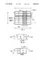
- FIG. 1is a diagram illustrating the relationship between frequency and time for an MFM signal packet
- FIGS. 2a and 2bare conceptual block diagrams illustrating the transmitter and receiver sections, respectively, for an MFM communication system according to the principles of the present invention
- FIG. 3is a diagram illustrating the complex envelope for one QPSK tone
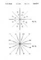
- FIGS. 4a-4dare phase plot diagrams illustrating the phase encoding for DQPSK encoding
- FIG. 5is a functional block diagram of an MFM communications system according to the principles of the present invention.
- FIG. 6is a functional block diagram of the transmitter block shown in the block diagram of FIGS. 2a and 5;
- FIG. 7is a functional block diagram of the receiver block shown in the system of FIGS. 2b and 5;
- FIG. 8is a functional block diagram of the data acquisition board shown in FIG. 7;
- FIG. 9is a flow diagram illustrating multi-frequency differential quadrature phase shift keyed modulation in accordance with the principles of the present invention.
- FIG. 10is a flow diagram illustrating demodulation and decoding for multi-frequency differential quadrature phase shift keyed modulation in accordance with the principles of the present invention
- FIG. 11ais a diagram illustrating the transition states for multi-frequency differential 16-quadrature amplitude modulation according to the principles of the present invention
- FIG. 11bis a diagram illustrating the decoded phase values for the differential encoding strategy shown in FIG. 11a;
- FIG. 12is a diagram illustrating a decoding decision tree for decoding differentially encoded data in accordance with the encoding strategy shown in FIGS. 11a and 11b;
- FIG. 13is a flow chart illustrating a transmit algorithm for use in the transmit microcomputer shown in FIG. 5;
- FIG. 14is a flow chart illustrating another transmit algorithm for use in the transmit microcomputer shown in FIG. 5;
- FIG. 15is a flow chart illustrating a receive algorithm used in the receive microcomputer shown in FIG. 5.
- an analog multi-frequency modulation (MFM) transmit signal generated according to the principles of the present inventioncomprises "packets" of multiple tones or frequencies which are differentially modulated in amplitude and/or phase between adjacent frequencies.
- the tones 13are present simultaneously during a subinterval of the packet 11 known as a baud 15.
- the packets 11can be located arbitrarily in the frequency spectrum and in time.
- f x1/ ⁇ t: Sampling or clock frequency for digital-to-analog and analog-to-digital conversion in Hz.
- f1/ ⁇ T: Frequency spacing (minimum) between MFM tones.
- nis discrete time referenced to the beginning of the baud 15.
- kmay take on all integer values between 1 and k x /2 -1; k is referred to as the "harmonic number" of the MFM tone of frequency k ⁇ f.
- a baud 15 interval, i.e., a time ⁇ T,contains exactly k cycles of tone k.
- adjacent tonesdiffer by one in the number of cycles they make during a baud 15.
- the discrete time signal defined by equation (3)is given by the k x point Inverse Discrete Fourier Transform (IDFT) of equation (5):
- the 1 th baud 15is generated by taking the IDFT of a complex valued array of length k x called the frequency domain array (FDA).
- the first half of the arrayis loaded with the amplitudes and phases of the tones to be included in the MFM signal at the corresponding harmonic numbers.
- the second half of the arrayis loaded with the complex conjugate of values in the first half of the array at the image harmonics (the image harmonic of k is k x -k).
- the complex conjugate symmetry about the midpointinsures that the IDFT, also an array of k x points called the time domain array (TDA), will be real valued.
- the values in the TDA, x 1 (n), defined by equation (7)comprise the discrete time samples for the digitally modulated analog MFM transmit signal waveform.
- FIGS. 2a and 2ba block diagram of a transmitter section 21 and a receiver section 23, respectively, are shown.
- the k x point DFT of x 1 (n), as defined by equations (5) and (6), i.e., the complex valued FDAis loaded on line 22 into the IDFT block 25 to provide a set of discrete time samples in the TDA corresponding to the desired MFM analog transmit signal.
- the samplesare clocked out via DAC 27 at a clock frequency 24 of f x to provide the desired analog transmit signal x 1 (u) on line 28.
- a complete signal packet 11is generated by L repetitions of the above described process.
- Demodulation of MFMis the inverse of the signal generation process.
- the received analog signal, y 1 (u), on line 36 at the receiver 23is sampled at the clock 34 frequency, f x samples per second, and converted to a digital format via ADC 29.
- the sampled valuesare loaded into a k x point real valued array, called the receive time domain array (TDA), in DFT block 31.
- TDAreceive time domain array
- a DFTis computed of the array to obtain the complex valued frequency domain array (FDA) of the sampled input on line 32.
- the k x point DFTyields the complex valued receive FDA, Y 1 (k), containing, in its first half, the amplitude and phase modulation information, A lk and ⁇ lk , of all the harmonics of the transmit signal waveform.
- the demodulation operationcan be considered linear. Only K out of the k x complex values are retained for decoding. Also, the upper half of the receive FDA is redundant; it contains the complex conjugates of the values at the image frequencies in the lower half of the array and is not retained for processing. Also, nonused harmonics in the lower half of the array will, in the absence of noise, contain zero values and can be discarded. When they do contain noise values, their discard is equivalent to filtering out the unused portion of the spectrum at the output of the demodulation stage. Alternatively, the noise values may be used to estimate the noise level in the system.
- the K tones of the L baudsform a set of LK orthogonal signals so that the response of a matched filter, or correlator, to any of the tones (regardless of its modulation) other than the one to which it is matched is zero. Since the receiver 23 is linear, and a matched filter assures that it is optimal for demodulation of MFM, the signal-to-noise ratio is maximized in the presence of additive white noise. This is so in spite of unknown communication channel or line attenuation at each of the frequencies.
- the channelneed only have constant attenuation over narrow frequency bands corresponding to the bandwidths of the individual tones, ⁇ f, and not over the entire bandwidth W.
- the demodulationis still optimal for a wideband signal propagating through a channel with substantial variation in gain across the band.
- Modulation of the MFM signalcan be uniquely accomplished in a number of ways.
- the signal x 1 (n), as defined in equation (3),can be modulated in amplitude, frequency and phase, by translating the data into changes in A 1k , k and ⁇ 1k respectively.
- any combination of the modulation typesis also possible, such as changing amplitude and phase to produce quadrature amplitude modulation (QAM).
- the MFM signalcan be bandpass or baseband and through further multiplication with a carrier frequency, x 1 (n) can be translated to any frequency band desired.
- Bandpass signals modulated using quadrature phase shift keying (QPSK) and differential quadrature phase shift keying (DQPSK)are described in detail hereinbelow.
- Decoding QPSK directly into bitsis accomplished easily as follows. Assuming a coherent receiver, decoding requires evaluation of the polarity of the real and imaginary components of the K complex values stored in the receive frequency domain array. As shown in FIG. 3, the symbol mapping uses Gray encoding. This reduces the probability of bit error as errors caused by AWGN are likely to occur when the adjacent symbol is selected for the transmitted symbol; thus, the symbol error will contain only one bit error. Gray encoding also allows decoding directly into di-bits, with the right bit determined by the polarity of the real component and the left bit by the polarity of the imaginary component. The digital data is obtained by successively decoding each tone of each baud.
- MFDQPSKprovides a practical solution to the phase uncertainty problem by translating the original symbol set into a second "differential" symbol set, or set of states which can be evaluated to provide a set of modulation values, which is then encoded as QPSK.
- Translated symbolsare generated based on the input symbol and the previous translated symbol.
- FIGS. 4a-4dillustrate this translation. As shown, regardless of the previous symbol, an input of ⁇ 00 ⁇ generates a new symbol in the same quadrant as the previous symbol.
- decodingis performed by determining the phase difference between successive pairs of tones.
- phase differenceIn the absence of noise, the phase difference will be 0, ⁇ /2 or ⁇ radians.
- FIG. 5is a functional block diagram of an MFM communications system according to the principles of the present invention.
- the MFM communications system of the present inventioncomprises a transmitter section 51 wherein digital data input on line 62 is modulated in a desired frequency band to provide an MFM analog transmit signal which is coupled to a communications channel 55 for propagation to a receiver section 53.
- the receiver section 53demodulates the received analog signal including any noise introduced in the communication channel 55 to provide the original source data output on line 66 in digital form.
- the input data on line 62may be any information or message which may be represented in a digital format.
- TDAtime domain array
- All modulation/demodulation and encoding/decoding functionsare performed entirely internally by industry standard microcomputers, such as personal computers (an IBM AT Personal Computer including a floating point array processor is suitable for this application), under the control of special purpose transmit and receive computer programs thereby eliminating the need for special purpose modems to translate between the digital and analog domains.
- the transmit microcomputer 57is coupled to the communication channel 55 via its I/O ports 63 and DAC 65.
- the receive microcomputer 59is coupled to the communications channel 55 via ADC 67 and its internal I/O ports 71.
- Matched filter 69provides baud synchronization within each packet.
- the communications channel 55may be any available communications link linking the transmit 57 and the receive 59 microcomputers together.
- the medium for transmitting the datamay be wire or optical fiber, or it may be radio frequency such as HF, microwave or satellite.
- FIG. 6is a functional block diagram of the transmitter section 51.
- the input datais processed and may be transmitted immediately, i.e., in real time, or stored for transmission at a later time.
- the digital input to the encoder 511is a serial string of a binary digits. Processing by the encoder 511 is performed on a baud by baud basis until the end of the data file or the maximum packet length has been obtained.
- the encoder 511encodes the input data words or symbols into complex valued symbols which are stored in a frequency domain array (FDA), a file defined in the system memory (not shown).
- FDAfrequency domain array
- the value of the input symbolsis a function of the type of modulation.
- QPSK symbolscorrespond to two-bit, or di-bit, words and are encoded as discussed hereinabove.
- a discrete signalis produced by computing the IDFT 513 of the complex valued FDA array and is loaded into the packet storage area 515 in a time domain array (TDA).
- TDAtime domain array
- the controller 519determines the parameters of the packet based on the modulation type, baud rate and message size.
- the controllersequences the input data through the transmitter section 51 one baud at a time until the entire message has been processed.
- the entire stored digital signal, x 1 (n)is transferred from the TDA at a selected clock rate, f x samples per second, through DAC 517.
- filtering of the analog output signalmay be desired to remove high frequency amplitude discontinuities introduced by DAC 517.
- FIG. 7is a functional block diagram of the receiver section 53.
- the data acquisition board 531samples the input analog signal at the clock rate f x samples per second, and converts it to a digital format via ADC 67. Filtering of the analog input signal may be required to bandlimit input noise and to reject out of band interference from frequencies greater than f x /2.
- the digital data sequence thus obtainedis stored as a time domain packet or array (TDA) in the receive microcomputer 59 data storage 533.
- the stored real value data sequenceis accepted from the receive TDA one baud at a time to perform a k x point DFT 535.
- the first half of the resulting complex valuesare decoded in decode block 537 to obtain the amplitude and phase modulation information.
- the receiver section controller 539sequences the data through the receive section 53.
- the receive microcomputer 59As a function of the processing speed and capacity of the receive microcomputer 59, some delay may be introduced to the receive section from input to output. For real time processing, the receive microcomputer 59 must have the capability to complete the k x point DFT 535 in the same or less time than it takes to fill up one baud length buffer in the receive TDA. In a microcomputer utilizing parallel TDP buffers, data processing can alternate between buffers and data flow will be continuous through the system at the sampling rate.
- the MFM signalis implemented in the form of a transmission packet.
- the receiver section 53To acquire the packet, the receiver section 53 must know when to start sampling. This is accomplished by packet synchronization. Typically, unique words are inserted to mark the start of each packet or frame. In the preferred embodiment, the unique word is termed a "synchronization baud", and is added at the beginning of each packet.
- the synchronization baudis generated similarly to the other bauds in the packet, except that the tones and phases are predetermined. Acquisition of data by the receiver section 53 commences after successful detection of the synchronization baud.
- FIG. 8is a detailed block diagram of the data acquisition board 531 for the receive section 53.
- Frame synchronization of DQPSK MFM in the present inventionis achieved utilizing a polarity-only matched filter or polarity coincidence correlator.
- the data acquisition board 531comprises ADC 67 which couples a 12-bit digital data signal on line 541 to AND gate 547 and also couples a single bit signal on line 542 to the matched filter 69 (as shown in FIG. 5).
- the matched filter 69provides sampling triggers to the AND gate 547 synchronized with respect to the time of arrival of the input data packet.
- the hard limiter 544comprises a fast, high precision, high gain operational amplifier utilized to obtain the polarity information in the analog input signal.
- the output of the hard limiter 544is positive and zero, respectively.
- This unipolar signalis synchronized to the receiver section 53 clock frequency, f x , as it is clocked through a 128 point polarity-only matched filter 543.
- the hard limiter 544 slew rateshould be as large as possible. (an LM 318 general purpose operational amplifier having a slew rate of 70 volts per microsecond is suitable for this purpose.)
- the polarity-only matched filter 543 described aboveis realized by a commerically available CMOS programmable digital correlator comprising four, 32-bit correlator modules in series to form a 1 ⁇ 128-bit fixed channel configuration.
- a single bitis clocked in from ADC 67 on line 542 to be compared against a 128-bit preloaded reference pattern.
- a matchoccurs when the synchronization baud for each packet in the received signal is clocked through ADC 67 (a TMC2221 TTL compatible CMOS correlator manufactured by TRW LSI Products Inc. is suitable for this purpose.)
- a synchronization trigger generated when a match occursenables D flip-flop 548 to couple sampling triggers to AND gate 547 for data acquistion at the beginning of each data packet as required for the demodulation process.
- the MFM communications system of the present inventionmay be implemented in a variety of ways utilizing various software and hardware configurations.
- the host computer direct memory access (DMA)is utilized. Any desired packet construction may be used and various baud rates are available to provide greater flexibility in adapting the packet to available channel parameters. For example, in MFDQPSK modulation, where the information is represented by the phase difference between adjacent tones, channel tone distortion affects a shorter baud more than a longer baud due to the greater tone spacing. A longer baud is preferred when differential encoding is between adjacent tones. A short duration baud is desirable with differential coding between the same tones on adjacent bauds.
- FIGS. 9 and 10are a flow chart illustrating multi-frequency differential quadrature phase shift keyed (MFDQPSK) modulation and demodulation in which 2 bits of data are encoded into each tone.
- the resultant MFM signaltransmits 2 bits per Hz of the channel bandwidth occupied.
- FIG. 9The encoding and generation of the MFDQPSK signal is illustrated in FIG. 9 in which all blocks 91-101 may be resident in a computer software program executed by the transmit microcomputer 57. Alternatively, some or all of the blocks may be implemented in hardware or firmware, such as in a DSP chip.
- Input data to be transmittedare placed in a Data File 1 (91) in a 2-bit or di-bit format.
- the differential encoding step 93differentially encodes the phase transferring the encoded di-bits to Data File 2 (95).
- Data File 2is created with an additional initial state set to S o .
- the first di-bit from Data File 1is then encoded into the second state of Data File 2 according to the state transition diagram shown in FIG. 4a.
- the second di-bit from Data File 1is encoded into the third state of Data File 2 in accordance with the state transition diagrams of FIGS. 4a-4d where the beginning state is the previous state of Data File 2. This process is continued until all K di-bits from Data File 1 have been differentially encoded into K+ 1 states of Data File 2. Each of the K+1 digital states provide a modulation value for modulating one of the set of available tones. Examples of Data File 1 and Data File 2 are shown in Table III.
- Encoding Step 2 (97)provides amplitude and phase encoding of the K+1 states from Data File 2 into the available tones or carrier frequencies and creates a complex-valued frequency domain array (FDA) file 99 consisting of k x complex entries.
- K+1 of the complex entries in this file somewhere between the first entry, entry 0, and entry k x /2-1will be encoded according to the states of Data File 2 as follows: Assume entry number k 1 is the first non-zero entry in the FDA File 99. The first state in Data File 2 is always S o so entry k 1 will be loaded with a real part of 1. and an imaginary part of 1.
- the second half of the entries in FDAare encoded according to the complex conjugate image rule.
- This ruleis the following:
- the image of entry k in the first half of the FDA 99is entry k x -k.
- the real part of entry k x -kis set to the same value as the real part of entry k.
- the imaginary part of entry k x -kis set to the negative of the imaginary part of entry k.
- Table IIIfor a Data File 1 consisting of 4 di-bits
- Table IVfor an FDA 99 consisting of 16 complex entries. In this illustration, k 1 has been chosen to be entry 2.
- the FDA 99is transformed to the time domain array (TDA) 101 by means of a k x point Inverse Discrete Fourier Transformation (IDFT) 100. Because of the complex conjugate image symmetry introduced in the FDA 99 the result of the IDFT 100 is real-valued.
- the TDA 101consists of k x real-valued entries. Each real value is stored as an integer-valued byte. These bytes are sent via an I/O port 63 of the transmitting computer 57 to a DAC 65 which is clocked by a clock 64 operating at f x clock pulses per second. An external clock may be provided.
- the clock rate f xmay be any value from 0 to an upper limit set by the host computer's 57 ability to transfer bytes from the TDA 101 to the I/O port 63.
- f x61440.
- the host computercomprises an IBM PC/AT and the I/O port utilized is the direct memory access (DMA) channel.
- the DAC 65converts the byte representation of the digital signal samples to voltage levels thus providing an analog transmit signal which is coupled to the communications channel 55 connecting the data source and destination.
- the analog transmit signalcontains K+1 tones spaced at intervals of 1/ ⁇ T beginning at frequency k 1 / ⁇ T and ending with frequency k 2 / ⁇ T.
- the maximum value for k 2is (k x /2-1) which is less than f x /2 as required by the Nyquist Sampling Theorem.
- the MFDQPSK modulation systemoperates at a baud rate of 1/ ⁇ T with a bit rate of 2K/ ⁇ T.
- the system implementedselectively operates at baud rates of 15, 30, 60, 120, and 240 bauds per second with a constant bit rate of 8192 bits per second in a 4000 Hz bandpass channel.
- the signal flow diagram for receiving and decoding the MFDQPSK signalis shown in FIG. 10.
- the received analog signalis synchronized and digitized by data acquisition board 531 (as shown in FIG. 7 and 8) which couples digitized, real-valued data to the receive time domain array or packet (TDA) 103.
- Process blocks 103-115are internal to the receiving computer and are implemented as a computer software program. Alternatively, some or all of process blocks may be implemented in hardware of firmware.
- Receive ADC 67must be clocked at the same rate, f x , as the DAC 65 in transmit section 51 with an accuracy of plus or minus f x /(16k 2 ) Hz.
- Baud synchronization timing accuracymust be established to within plus or minus four clock cycles. In the preferred embodiment this is established without direct timing information from the transmit section 51 by preceding each packet of information bauds with a known synchronization baud and correlating it with a stored reference in matched filter 69 as described hereinabo
- the data acquisition board 531provides digitized received signal samples to a receive computer I/O port 71.
- the host receive computer 59stores these samples in the receive TDA 103 having k x times L entries in a real-valued array.
- the DFT 105 and Decoding Step 1 109transform k x entries at a time, that is one baud at a time, from the receive TDA 103 to the complex valued receive digital signal array (DSA) 111 according to the following procedures:
- the k x point DFT of the first k x real valued points in the TDA 103is obtained and only those (complex valued) coefficients between entry k 1 and k 2 are retained and placed in a temporary digital signal array 107. All other components of the transformation are discarded.
- the entry corresponding to k 1 +1is multiplied by the complex conjugate of the entry corresponding to k 1 to create a complex number with a phase equal to the phase difference between tones k 1 +1 and k 1 .
- This complex numberthen is multiplied by the complex number exp(j ⁇ /4), to add ⁇ /4 radians to the phase difference, and the result is stored as the first entry in the receive DSA 111.
- the same operationis performed on entries k 1 +2 and k 1 +1 and so forth until the final operation is performed on entries k 2 and k 2 -1 resulting in K complex entries in the receive DSA 111.
- the K complex entriesare decoded in Decoding Step 2 (113) to create Data File 3 (115) as follows: if the real part of the complex entry is positive, the least significant bit of the di-bit corresponding to that entry in the DSA 111 is made logical zero; if the least significant bit is negative, it is made logical one. The most significant bit of the di-bit is decoded from the imaginary part of the corresponding complex entry in the same manner. The final result is that the first K di-bits of Data File 1 (91) at the source (i.e., input data at the transmit section 51) have been transferred to Data File 3 (115) at the destination (i.e., receive section 53).
- This procedureis repeated on the remaining entries in the real valued data stored in the receive TDA 103, k x values at a time, until all L bauds in the packet have been decoded.
- k x1024
- a baud rate of 60 bauds per second, K of 64 and L of 30 bauds3840 bits of information are transmitted in a packet having an interval of 1/2 second in a 3960 Hz bandwidth.
- the bandmay be placed anywhere in the frequency spectrum from 60 Hz to 30,660 Hz simply by choosing different values for k 1 .
- multi-frequency differential 16-quadrature amplitude modulationdiffers from the MFDQPSK modulation described above in the following ways.
- the digital input datais stored in Data File 1 (91) in 4-bit words referred to as "nibbles", and are encoded into each tone using the 16 point state diagram or constellation shown in FIG. 11a.
- datais transmitted at 4 bits per Hz of allocated channel bandwidth.
- the state diagram for the differential encoding from frequency to frequencyis given in Table V for each of the 16 values for an input nibble.
- the diagramdefines the state for tone k+1 for the conditions that tone k is in an even numbered state, and that tone k is in an odd numbered state.
- Index ntakes on all values from 0 through 7 and the indicated index n addition is performed modulo 16.
- the first 3 bits i.e., the 3 most significant bits, of each input nibblerepresent phase and are differentially encoded as a Gray code so that differentially decoded phase symbols that are adjacent in phase only differ by 1 bit as shown in Table V.
- the fourth bit i.e., the least significant bit, of each input nibbleis an amplitude bit and is encoded such that the magnitude of tone k+1 is changed to the alternate amplitude if the amplitude bit is a logical zero but remains unchanged if it is a logical one.
- Table VIis an example of a 4-nibble message stored in Data File 1 and the differentially encoded data in Data File 2 (95).
- Table VIIillustrates the corresponding FDA file 99 after the amplitude and phase encoding process
- Demodulation of the MFD16-QAM receive TDPproceeds similarly as demodulation of the MFDQPSK to the point of creation of the temporary digital signal array 107.
- a 12-bit ADCis utilized in the data acquisition board 531 to reduce quantization noise.
- each complex entry in the temporary digital signal array 107is multiplied by the complex conjugate of the previous complex entry and the product is multiplied by the complex number exp(j ⁇ /8).
- the resulting complex productswill be the 24 possible points in the phase diagram or constellation shown in FIG. 11b.
- the largest amplitude pointsoccur when adjacent tones both have the large amplitude.
- the smallest amplitudesoccur when adjacent tones both have the smaller amplitude.
- the intermediate amplitudesoccur when the adjacent tones have different amplitudes, i.e., the amplitude bit is a logical zero.
- phase decoding rules shownare amplitude independent and are the optimum decision rules for decoding the phase in the presence of additive noise.
- the amplitude bitis decoded by comparing the magnitudes of the complex values in adjacent positions of the temporary digital signal array 107.
- the large and small magnitude tonesare created in a ratio of 5 to 3. If the received magnitudes of adjacent tones differ by more than 1/8 the magnitude of the sum, the amplitude bit is decoded as a logical zero, otherwise it is decoded as a logical one.
- K nibbles or K 4-bit wordshave been transferred from Data File 1 (91) at the transmit computer 57 to Data File 3 (115) of the receive computer 59.
- This demodulation and decoding processis repeated for each of the L bauds in the receive TDA 103 until 4KL bits (KL/2 bytes) have been transferred from Data File 1 at the transmitter 51 to Data File 3 of the receiver 53.
- K of 128, L of 15 and baud rate of 30 bauds per second960 bytes are transferred in 1/2 second in a 3960 Hz bandwidth at 15,360 bits/sec.
- TRANSMITa procedural flow diagram of a computer software program named TRANSMIT as implemented in the preferred embodiment is shown.
- the TRANSMIT programgenerates the MFM data signal and provides encoding of data files utilizing 16-QAM, QPSK and DQPSK methods.
- the programprovides for packet size, and generates a synchronization baud.
- EncodeQPSK 163begins by displaying a four symbol QPSK constellation which is used as a reference in selecting the symbols over the band.
- the symbols for the K tones in the baudcan be selected in a variety of ways: symbols for all tones may be randomly selected from a random generator; a symbol for each tone may be selected by the user; and individual tones may be removed from the band.
- the capability to remove tones from the bandallows construction of a baud with an arbitrary number of tones within the band determined by k 1 and k 2 . Selected symbols for the band are loaded into the complex frequency domain array with their complex conjugate image frequency.
- EncodeQAM 165is functionally identical to EncodeQPSK 163, except the symbols conform to a 16-QAM constellation (as shown in FIG. 11a).
- ComplexFFT 167computes the inverse FFT.
- ComplexFFT 167consumes the majority of the processing time in the program due to the complex arithmetic operations required, thus restricting the overall throughput of the system.
- the FFT algorithmis computed by a floating point array processor.
- Each value in the time domain arrayis represented as a real data type, occupying six bytes of memory.
- Scale Data 169converts these values down to a one byte format acceptable to the DAC and places them into a packet storage buffer. EncodeQPSK 163, ComplexFFT 167, and ScaleData 169 are executed for each baud, until all L baud have been processed.
- DMAINIT 171transfers samples at the clock frequency, f x samples per second over the DMA channel to the DAC.
- FIG. 14a procedural flow diagram of another transmit computer software program named XMITMES as implemented in another preferred embodiment is shown.
- the XMITMES programgenerates an MFM data signal which encodes and transmits an ASCII file using DQPSK.
- a synchronization baudis attached at the beginning of each packet.
- the XMITMES programhas a less complex structure than the TRANSMIT program described above because all tones are placed in a fixed band and are encoded utilizing DQPSK.
- the synchronization baud for XMITMESis a predetermined sequence generated by SyncBaud 173. This baud is constructed as are all other baud, except k x is fixed at 256, and tones 68 to 83, which are the tones in the fixed band, are encoded with the same random symbol pattern regardless of the packet construction or input message 176. This synchronization sequence occupies the first 256 values in the packet buffer and therefore is the first to be clocked out of the transmit computer 57.
- TailorPacket 174determines the maximum number of baud required for encoding. This is determined by dividing the number of characters in the message by the number of characters that can be encoded.
- DiffEncode 177encodes the message file 176 into the complex frequency domain-array. It reads one character at a time; then breaks the 8-bit character into four 2-bit words. The words are DQPSK encoded and stored in the frequency domain array. Once encoded, processing and signal output by ComplexFFT 179, ScaleData 181, and DMAINIT 183 proceed similarly as in TRANSMIT program.
- the RECEIVE programdemodulates the encoded MFM transmit signal generated by the TRANSMIT program.
- a user interactive procedure, PacketSetUp 185tailors the processing to the expected receive packet, using the inputs k x and L.
- AcquireData 187allocates memory to store the sampled values transferred from the board using the receive computer DMA controller.
- Direct Memory Accessis the only data transfer mode capable of transferring data to memory at the required rate without disruption by other interrupt processes in the computer.
- Other important initialization parametersare triggering source and the number of samples to be collected.
- the ADCmay be triggered from two sources, a programmable interval timer or an external trigger source (not shown).
- the programmable interval timerdivides either a 1 MHz or 10 MHz clock to derive the sampling rate of the trigger. After initialization, conversions take place on the positive transition of every trigger until the specified number of samples have been acquired and transferred to memory.
- DiffDecode 191demodulates the encoded symbols by differentially decoding the complex frequency array transformed from the sampled data by ComplexFFT 189. AcquireData 187 samples and stores a memory segment of data regardless of the packet size, Lk x . However, once stored, ConvertData, ComplexFFT 189, and DiffDecode 191 process only L baud of the data. DiffDecode 191 combines four differentially decoded symbols into one byte, representing the ordinal number of an ASCII character. To reconstruct the message, the characters are transferred to text file MESSAGE.DAT until processing is complete. When desired, ShowMessage 193 displays the recovered message.
Landscapes
- Engineering & Computer Science (AREA)
- Computer Networks & Wireless Communication (AREA)
- Signal Processing (AREA)
- Digital Transmission Methods That Use Modulated Carrier Waves (AREA)
Abstract
Description
x.sub.lk (u)=A.sub.lk cos (2πkΔfu+φ.sub.lk); 0 ≦u≦T. (2)
x.sub.lk (n)=A.sub.lk cos (2πkn/k.sub.x +φ.sub.lk); 0≦n≦k.sub.x -1. (4)
X.sub.1 (k)=0 , k=0, k.sub.x /2 (5)
x.sub.l (n)=IDFT[X.sub.l (k)]; 0≦k,n≦k.sub.x -1.(7)
TABLE I ______________________________________ k Re{X(k)} Im{X(k)} ______________________________________ 0 0 0 1 0 0 2 0 0 3 XR3 XI3 4 XR4 XI4 5 XR5 XI5 6 0 0 7 0 0 8 0 0 9 0 0 10 0 0 11 XR5 -XI5 12 XR4 -XI4 13 XR3 -XI3 14 0 0 15 0 0 ______________________________________TABLE II ______________________________________ Real Time Non real time ______________________________________ Storage required 2048 30720 (# of samples) Time required for ≦16.7 >16.7 processing 1024 samples (msec) ______________________________________
TABLE III ______________________________________Data File 1Data File 2 ______________________________________ S.sub.0 01 S.sub.1 10 S.sub.0 11 S.sub.3 00 S.sub.3 ______________________________________
TABLE IV ______________________________________ Frequency Domain Array k i r ______________________________________ 0 0.0 0.0 1 0.0 0.0 2 1.0 1.0 3 1.0 -1.0 4 1.0 1.0 5 -1.0 -1.0 6 -1.0 -1.0 7 0.0 0.0 8 0.0 0.0 9 0.0 0.0 10 1.0 -1.0 11 1.0 -1.0 12 -1.0 1.0 13 -1.0 -1.0 14 -1.0 1.0 15 0.0 0.0 ______________________________________
TABLE V ______________________________________ State for tone k + 1 Given that tone k is in state: Input Nibble S.sub.2n (Even) S.sub.2n+1 (Odd) ______________________________________ 0000 S.sub.2n+1 S.sub.2n 0001 S.sub.2n S.sub.2n+1 0010 S.sub.2n+3 S.sub.2n+2 0011 S.sub.2n+2 S.sub.2n+3 0110 S.sub.2n+5 S.sub.2n+4 0111 S.sub.2n+4 S.sub.2n+5 0100 S.sub.2n+7 S.sub.2n+6 0101 S.sub.2n+6 S.sub.2n+7 1100 S.sub.2n+9 S.sub.2n+8 1101 S.sub.2n+8 S.sub.2n+9 1110 S.sub.2n+11 S.sub.2n+10 1111 S.sub.2n+10 S.sub.2n+11 1010 S.sub.2n+13 S.sub.2n+12 1011 S.sub.2n+12 S.sub.2n+13 1000 S.sub.2n+15 S.sub.2n+14 1001 S.sub.2n+14 S.sub.2n+15 ______________________________________
TABLE VI ______________________________________Data File 1Data File 2 ______________________________________ S.sub.0 0 1 1 1 S.sub.4 1 1 0 0 S.sub.13 1 0 1 0 S.sub.8 1 0 0 1 S.sub.6 ______________________________________
TABLE VII ______________________________________ FREQUENCY DOMAIN ARRAY K i r ______________________________________ 0 0.0 0.0 1 0.0 0.0 2 .2296 .5543 3 .5543 -.2296 4 -.9239 .3827 5 -.2296 -.5543 6 .2296 -.5543 7 0.0 0.0 8 0.0 0.0 9 0.0 0.0 10 -.2296 -.5543 11 .2296 -.5543 12 .9239 .3827 13 -.5543 -.2296 14 -.2296 .5543 15 0.0 0.0 ______________________________________
Claims (30)
Priority Applications (6)
| Application Number | Priority Date | Filing Date | Title |
|---|---|---|---|
| US07/490,769US5063574A (en) | 1990-03-06 | 1990-03-06 | Multi-frequency differentially encoded digital communication for high data rate transmission through unequalized channels |
| US07/566,290US5166924A (en) | 1990-03-06 | 1990-08-10 | Echo cancellation in multi-frequency differentially encoded digital communications |
| CA002054906ACA2054906A1 (en) | 1990-03-06 | 1991-03-05 | Multi-frequency differentially encoded digital communication for high data rate transmission through unequalized channels |
| EP19910906644EP0471069A4 (en) | 1990-03-06 | 1991-03-05 | Multi-frequency differentially encoded digital communication for high data rate transmission through unequalized channels |
| AU75515/91AAU7551591A (en) | 1990-03-06 | 1991-03-05 | Multi-frequency differentially encoded digital communication for high data rate transmission through unequalized channels |
| PCT/US1991/001556WO1991014316A1 (en) | 1990-03-06 | 1991-03-05 | Multi-frequency differentially encoded digital communication for high data rate transmission through unequalized channels |
Applications Claiming Priority (1)
| Application Number | Priority Date | Filing Date | Title |
|---|---|---|---|
| US07/490,769US5063574A (en) | 1990-03-06 | 1990-03-06 | Multi-frequency differentially encoded digital communication for high data rate transmission through unequalized channels |
Related Child Applications (1)
| Application Number | Title | Priority Date | Filing Date |
|---|---|---|---|
| US07/566,290Continuation-In-PartUS5166924A (en) | 1990-03-06 | 1990-08-10 | Echo cancellation in multi-frequency differentially encoded digital communications |
Publications (1)
| Publication Number | Publication Date |
|---|---|
| US5063574Atrue US5063574A (en) | 1991-11-05 |
Family
ID=23949387
Family Applications (2)
| Application Number | Title | Priority Date | Filing Date |
|---|---|---|---|
| US07/490,769Expired - Fee RelatedUS5063574A (en) | 1990-03-06 | 1990-03-06 | Multi-frequency differentially encoded digital communication for high data rate transmission through unequalized channels |
| US07/566,290Expired - Fee RelatedUS5166924A (en) | 1990-03-06 | 1990-08-10 | Echo cancellation in multi-frequency differentially encoded digital communications |
Family Applications After (1)
| Application Number | Title | Priority Date | Filing Date |
|---|---|---|---|
| US07/566,290Expired - Fee RelatedUS5166924A (en) | 1990-03-06 | 1990-08-10 | Echo cancellation in multi-frequency differentially encoded digital communications |
Country Status (5)
| Country | Link |
|---|---|
| US (2) | US5063574A (en) |
| EP (1) | EP0471069A4 (en) |
| AU (1) | AU7551591A (en) |
| CA (1) | CA2054906A1 (en) |
| WO (1) | WO1991014316A1 (en) |
Cited By (70)
| Publication number | Priority date | Publication date | Assignee | Title |
|---|---|---|---|---|
| WO1993023809A1 (en)* | 1992-05-15 | 1993-11-25 | Connective Strategies, Inc. | Isdn-based high speed communication system |
| US5444697A (en)* | 1993-08-11 | 1995-08-22 | The University Of British Columbia | Method and apparatus for frame synchronization in mobile OFDM data communication |
| US5488632A (en)* | 1990-03-30 | 1996-01-30 | National Transcommunications Limited | Transmission and reception in a hostile interference environment |
| US5546429A (en)* | 1992-11-09 | 1996-08-13 | Motorola, Inc. | Frequency hopping code division multiple access radio communication unit |
| US5565764A (en)* | 1995-05-05 | 1996-10-15 | Texas Instruments Incorporated | Digital processing method for parameter estimation of synchronous, asynchronous, coherent or non-coherent signals |
| US5615404A (en)* | 1994-10-31 | 1997-03-25 | Intel Corporation | System having independently addressable bus interfaces coupled to serially connected multi-ported signal distributors generating and maintaining frame based polling schedule favoring isochronous peripherals |
| US5621901A (en)* | 1994-10-31 | 1997-04-15 | Intel Corporation | Method and apparatus for serial bus elements of an hierarchical serial bus assembly to electrically represent data and control states to each other |
| US5623610A (en)* | 1994-10-31 | 1997-04-22 | Intel Corporation | System for assigning geographical addresses in a hierarchical serial bus by enabling upstream port and selectively enabling disabled ports at power on/reset |
| US5694555A (en)* | 1994-10-31 | 1997-12-02 | Intel Corporation | Method and apparatus for exchanging data, status, and commands over an hierarchical serial bus assembly using communication packets |
| US5742847A (en)* | 1994-10-31 | 1998-04-21 | Intel Corporation | M&A for dynamically generating and maintaining frame based polling schedules for polling isochronous and asynchronous functions that guaranty latencies and bandwidths to the isochronous functions |
| US5802112A (en)* | 1996-01-16 | 1998-09-01 | Transcendat Inc. | Multi-level, multi-frequency interference pattern analog waveform encoding of digital data for transmission |
| EP0701345A3 (en)* | 1994-09-09 | 1999-09-22 | Sony Corporation | Multicarrier transmission using differential phases |
| US6038262A (en)* | 1998-06-09 | 2000-03-14 | Transcendata, Inc. | Method and apparatus for compensation of electro-magnetic distortion using weighted feedback delay for amplitude coded sinusoidal waveform generation and transmission |
| WO2000033501A3 (en)* | 1998-11-17 | 2000-08-10 | Pauli Lallo | Adaptive modem and method for adaptive election of modulation mode |
| US6175550B1 (en)* | 1997-04-01 | 2001-01-16 | Lucent Technologies, Inc. | Orthogonal frequency division multiplexing system with dynamically scalable operating parameters and method thereof |
| US6192068B1 (en) | 1996-10-03 | 2001-02-20 | Wi-Lan Inc. | Multicode spread spectrum communications system |
| EP1087583A2 (en) | 1999-09-17 | 2001-03-28 | Lucent Technologies Inc. | Differential coding in the frequency domain, for multicarrier transmission |
| US6304611B1 (en)* | 1997-06-19 | 2001-10-16 | Hitachi Denshi Kabushiki Kaisha | OFDM modulator and OFDM modulation method for digital modulated wave having guard interval |
| USH2015H1 (en) | 1995-03-31 | 2002-03-05 | The United States Of America As Represented By The Secretary Of The Navy | Communications system using a sharply bandlimited keying waveform |
| US6381251B1 (en) | 1997-06-12 | 2002-04-30 | Hitachi Denshi Kabushiki Kaisha | Data transmission apparatus and receiving apparatus using orthogonal frequency division multiplex modulation system |
| EP0870368A4 (en)* | 1995-08-22 | 2002-05-02 | Digital Compression Technology | Compressive communication and storage system |
| US6393051B1 (en)* | 1998-06-30 | 2002-05-21 | Fujitsu Limited | Digital subscriber line communicating system and a transceiver in the system |
| USRE37802E1 (en) | 1992-03-31 | 2002-07-23 | Wi-Lan Inc. | Multicode direct sequence spread spectrum |
| WO2002068777A1 (en)* | 2001-02-26 | 2002-09-06 | Worldstage, Llc | Integrated, adaptable theater, club and multiplex |
| US6456649B1 (en)* | 1996-09-02 | 2002-09-24 | Stmicroelectronics N.V. | Multi-carrier transmission systems |
| US20020138807A1 (en)* | 2001-03-26 | 2002-09-26 | Quang Nguyen | Optimum UMTS modem |
| US20020136282A1 (en)* | 2001-03-26 | 2002-09-26 | Quang Nguyen | Optimum UMTS modem |
| US6463094B2 (en)* | 1998-04-14 | 2002-10-08 | Smart Link Ltd. | Point-to-point secure modem and method |
| US20030002533A1 (en)* | 2000-02-03 | 2003-01-02 | Doron Rajwan | Coding method |
| US20030100282A1 (en)* | 1999-06-29 | 2003-05-29 | Srinivas Kandala | Data unit detection including antenna diversity |
| US6654431B1 (en) | 1999-09-15 | 2003-11-25 | Telcordia Technologies, Inc. | Multicarrier personal access communication system |
| US20040044521A1 (en)* | 2002-09-04 | 2004-03-04 | Microsoft Corporation | Unified lossy and lossless audio compression |
| US20040044520A1 (en)* | 2002-09-04 | 2004-03-04 | Microsoft Corporation | Mixed lossless audio compression |
| US6874115B1 (en)* | 2000-08-04 | 2005-03-29 | Agere Systems Inc. | Multi-mode decoding for digital audio broadcasting and other applications |
| US20050100120A1 (en)* | 1998-04-17 | 2005-05-12 | Melbourne Barton | Wireless internet access system and method |
| EP1072116A4 (en)* | 1998-04-17 | 2005-08-03 | Telcordia Tech Inc | A wireless internet access method and system |
| US20070116209A1 (en)* | 1995-02-06 | 2007-05-24 | Adc Telecommunications, Inc. | Multipoint-to-point communication using orthogonal frequency division multiplexing |
| US7239666B1 (en) | 1994-09-09 | 2007-07-03 | Sony Corporation | Communication system |
| CN1324823C (en)* | 2004-08-02 | 2007-07-04 | 北京天碁科技有限公司 | Method and device for channel evaluation using training sequence |
| US7498999B2 (en) | 2004-11-22 | 2009-03-03 | Ruckus Wireless, Inc. | Circuit board having a peripheral antenna apparatus with selectable antenna elements and selectable phase shifting |
| US7498996B2 (en) | 2004-08-18 | 2009-03-03 | Ruckus Wireless, Inc. | Antennas with polarization diversity |
| US7511680B2 (en) | 2004-08-18 | 2009-03-31 | Ruckus Wireless, Inc. | Minimized antenna apparatus with selectable elements |
| US7525486B2 (en) | 2004-11-22 | 2009-04-28 | Ruckus Wireless, Inc. | Increased wireless coverage patterns |
| US20090248424A1 (en)* | 2008-03-25 | 2009-10-01 | Microsoft Corporation | Lossless and near lossless scalable audio codec |
| US20090304131A1 (en)* | 2008-06-06 | 2009-12-10 | Weifeng Wang | Low cost noise floor reduction |
| US7639106B2 (en) | 2006-04-28 | 2009-12-29 | Ruckus Wireless, Inc. | PIN diode network for multiband RF coupling |
| US7646343B2 (en) | 2005-06-24 | 2010-01-12 | Ruckus Wireless, Inc. | Multiple-input multiple-output wireless antennas |
| US7652632B2 (en) | 2004-08-18 | 2010-01-26 | Ruckus Wireless, Inc. | Multiband omnidirectional planar antenna apparatus with selectable elements |
| US7696946B2 (en) | 2004-08-18 | 2010-04-13 | Ruckus Wireless, Inc. | Reducing stray capacitance in antenna element switching |
| USRE41771E1 (en) | 1995-02-06 | 2010-09-28 | Adc Telecommunications, Inc. | System for multiple use subchannels |
| US7880683B2 (en) | 2004-08-18 | 2011-02-01 | Ruckus Wireless, Inc. | Antennas with polarization diversity |
| USRE42236E1 (en) | 1995-02-06 | 2011-03-22 | Adc Telecommunications, Inc. | Multiuse subcarriers in multipoint-to-point communication using orthogonal frequency division multiplexing |
| US7965252B2 (en) | 2004-08-18 | 2011-06-21 | Ruckus Wireless, Inc. | Dual polarization antenna array with increased wireless coverage |
| US8031129B2 (en) | 2004-08-18 | 2011-10-04 | Ruckus Wireless, Inc. | Dual band dual polarization antenna array |
| US8068068B2 (en) | 2005-06-24 | 2011-11-29 | Ruckus Wireless, Inc. | Coverage antenna apparatus with selectable horizontal and vertical polarization elements |
| US8217843B2 (en) | 2009-03-13 | 2012-07-10 | Ruckus Wireless, Inc. | Adjustment of radiation patterns utilizing a position sensor |
| US8275077B1 (en)* | 2010-10-13 | 2012-09-25 | The United States Of America As Represented By The Director, National Security Agency | Coherent demodulation of ais-GMSK signals in co-channel |
| US8686905B2 (en) | 2007-01-08 | 2014-04-01 | Ruckus Wireless, Inc. | Pattern shaping of RF emission patterns |
| US8698675B2 (en) | 2009-05-12 | 2014-04-15 | Ruckus Wireless, Inc. | Mountable antenna elements for dual band antenna |
| US8756668B2 (en) | 2012-02-09 | 2014-06-17 | Ruckus Wireless, Inc. | Dynamic PSK for hotspots |
| US20140169423A1 (en)* | 2007-08-14 | 2014-06-19 | Infineon Technologies Ag | Sensor that transmits signals responsive to a request signal and receives information |
| US9019165B2 (en) | 2004-08-18 | 2015-04-28 | Ruckus Wireless, Inc. | Antenna with selectable elements for use in wireless communications |
| US9092610B2 (en) | 2012-04-04 | 2015-07-28 | Ruckus Wireless, Inc. | Key assignment for a brand |
| US9407012B2 (en) | 2010-09-21 | 2016-08-02 | Ruckus Wireless, Inc. | Antenna with dual polarization and mountable antenna elements |
| RU2608178C2 (en)* | 2015-06-10 | 2017-01-17 | Федеральное государственное бюджетное образовательное учреждение высшего профессионального образования "Омский государственный технический университет" | Method of power-stealthy transmission of discrete messages over radio communication channels |
| US9570799B2 (en) | 2012-09-07 | 2017-02-14 | Ruckus Wireless, Inc. | Multiband monopole antenna apparatus with ground plane aperture |
| US9634403B2 (en) | 2012-02-14 | 2017-04-25 | Ruckus Wireless, Inc. | Radio frequency emission pattern shaping |
| US20180019906A1 (en)* | 2016-07-18 | 2018-01-18 | Intel Corporation | Apparatus, system and method of communicating a transmission according to a rotated 256 quadrature amplitude modulation (qam) scheme |
| US10186750B2 (en) | 2012-02-14 | 2019-01-22 | Arris Enterprises Llc | Radio frequency antenna array with spacing element |
| US10230161B2 (en) | 2013-03-15 | 2019-03-12 | Arris Enterprises Llc | Low-band reflector for dual band directional antenna |
Families Citing this family (48)
| Publication number | Priority date | Publication date | Assignee | Title |
|---|---|---|---|---|
| GB9020170D0 (en)* | 1990-09-14 | 1990-10-24 | Indep Broadcasting Authority | Orthogonal frequency division multiplexing |
| USRE40241E1 (en) | 1991-03-27 | 2008-04-15 | Matsushita Electric Industrial Co., Ltd. | Communication system |
| USRE42643E1 (en) | 1991-03-27 | 2011-08-23 | Panasonic Corporation | Communication system |
| USRE39890E1 (en) | 1991-03-27 | 2007-10-23 | Matsushita Electric Industrial Co., Ltd. | Communication system |
| US5600672A (en) | 1991-03-27 | 1997-02-04 | Matsushita Electric Industrial Co., Ltd. | Communication system |
| US5892879A (en)* | 1992-03-26 | 1999-04-06 | Matsushita Electric Industrial Co., Ltd. | Communication system for plural data streams |
| US6724976B2 (en) | 1992-03-26 | 2004-04-20 | Matsushita Electric Industrial Co., Ltd. | Communication system |
| US7894541B2 (en)* | 1992-03-26 | 2011-02-22 | Panasonic Corporation | Communication system |
| US6728467B2 (en) | 1992-03-26 | 2004-04-27 | Matsushita Electric Industrial Co., Ltd. | Communication system |
| US7302007B1 (en) | 1992-03-26 | 2007-11-27 | Matsushita Electric Industrial Co., Ltd. | Communication system |
| USRE38513E1 (en) | 1992-03-26 | 2004-05-11 | Matsushita Electric Industrial Co., Ltd. | Communication system |
| US5802241A (en) | 1992-03-26 | 1998-09-01 | Matsushita Electric Industrial Co., Ltd. | Communication system |
| CA2332405C (en)* | 1992-03-26 | 2007-01-23 | Matsushita Electric Industrial Co., Ltd. | Communication system |
| US5317596A (en)* | 1992-12-01 | 1994-05-31 | The Board Of Trustees Of The Leland Stanford, Junior University | Method and apparatus for echo cancellation with discrete multitone modulation |
| JPH08511664A (en)* | 1993-06-07 | 1996-12-03 | アルカテル・モビル・フオンズ | Signal packet for a communication system having a reference modulated according to a time-dependent law |
| US5467374A (en)* | 1993-10-29 | 1995-11-14 | General Electric Company | Low complexity adaptive equalizer for U.S. digital cellular radio receivers |
| US5623513A (en)* | 1993-12-13 | 1997-04-22 | Amati Communications Corporation | Mitigating clipping and quantization effects in digital transmission systems |
| US5684825A (en)* | 1994-03-23 | 1997-11-04 | Paradyne Corporation | Independently switched voice and data calls using a simultaneous voice and data modem |
| US5732113A (en)* | 1996-06-20 | 1998-03-24 | Stanford University | Timing and frequency synchronization of OFDM signals |
| DE19638654A1 (en)* | 1996-09-20 | 1998-03-26 | Siemens Ag | Digital message transmission method |
| US6618480B1 (en)* | 1997-04-30 | 2003-09-09 | Texas Instruments Incorporated | DAC architecture for analog echo cancellation |
| US6092040A (en)* | 1997-11-21 | 2000-07-18 | Voran; Stephen | Audio signal time offset estimation algorithm and measuring normalizing block algorithms for the perceptually-consistent comparison of speech signals |
| US6130918A (en)* | 1997-12-01 | 2000-10-10 | Nortel Networks Limited | Method and apparatus for reducing the peak-to-average ratio in a multicarrier communication system |
| US6097776A (en)* | 1998-02-12 | 2000-08-01 | Cirrus Logic, Inc. | Maximum likelihood estimation of symbol offset |
| BRPI9815801B1 (en)* | 1998-04-14 | 2015-08-25 | Fraunhofer Ges Zur Förderung Der Angewand Ten Forschung E V | Echo phase offset correction in a multi-carrier demodulation system |
| US6891887B1 (en) | 1998-05-27 | 2005-05-10 | 3Com Corporation | Multi-carrier LAN adapter device using interpolative equalizer |
| US6507585B1 (en) | 1998-05-27 | 2003-01-14 | 3Com Corporation | Multi-carrier LAN adapter device using frequency domain equalizer |
| US6704317B1 (en) | 1998-05-27 | 2004-03-09 | 3Com Corporation | Multi-carrier LAN modem server |
| US6377683B1 (en) | 1998-05-29 | 2002-04-23 | 3Com Corporation | Low complexity frequency domain echo canceller for DMT transceivers |
| US6603811B1 (en) | 1998-05-29 | 2003-08-05 | 3Com Corporation | Low complexity frequency domain equalizer having fast re-lock |
| US6304594B1 (en)* | 1998-07-27 | 2001-10-16 | General Dynamics Government Systems Corporation | Interference detection and avoidance technique |
| KR100293615B1 (en)* | 1998-09-07 | 2002-05-01 | 김춘호 | Carrier Frequency Offset Estimation Method Using Reference Symbol Composed of Repetitive Signals in OPM System |
| US6657950B1 (en)* | 1999-02-19 | 2003-12-02 | Cisco Technology, Inc. | Optimal filtering and upconversion in OFDM systems |
| US6434188B1 (en)* | 1999-04-07 | 2002-08-13 | Legerity, Inc. | Differential encoding arrangement for a discrete multi-tone transmission system |
| US6643271B1 (en) | 1999-04-30 | 2003-11-04 | 3Com Corporation | Adjustable gain transmit cancellation in a full-duplex modem data access arrangement (DAA) |
| US6751202B1 (en) | 1999-04-30 | 2004-06-15 | 3Com Corporation | Filtered transmit cancellation in a full-duplex modem data access arrangement (DAA) |
| US6826279B1 (en)* | 2000-05-25 | 2004-11-30 | 3Com Corporation | Base band echo cancellation using laguerre echo estimation |
| US20020191779A1 (en)* | 2001-03-23 | 2002-12-19 | Tien Pham | System for convolutional echo cancellation by iterative autocorrelation |
| US20020181699A1 (en)* | 2001-03-23 | 2002-12-05 | Tien Pham | System for convolutional echo cancellation by iterative autocorrelation |
| US8194526B2 (en)* | 2005-10-24 | 2012-06-05 | General Motors Llc | Method for data communication via a voice channel of a wireless communication network |
| US8279912B2 (en)* | 2006-03-13 | 2012-10-02 | Plx Technology, Inc. | Tranceiver non-linearity cancellation |
| US7684313B2 (en)* | 2007-03-30 | 2010-03-23 | Zoran Corporation | System and method for FFT window timing synchronization for an orthogonal frequency-division multiplexed data stream |
| US7903750B2 (en)* | 2007-09-11 | 2011-03-08 | Zoran Corporation | System and method for determining transmission parameters in an orthogonal frequency-division multiplexed data stream |
| US8295214B2 (en) | 2010-04-22 | 2012-10-23 | Plx Technology, Inc. | Reducing transmit signal components of a receive signal of a transceiver |
| US8995539B2 (en)* | 2010-07-13 | 2015-03-31 | Qualcomm Incorporated | Methods and apparatus for selecting and using communications resources in a communication system |
| US8254490B2 (en) | 2010-07-19 | 2012-08-28 | Plx Technology, Inc. | Reducing transmit signal components of a receive signal of a transceiver using a shared DAC architecture |
| DE102013212067A1 (en) | 2013-06-25 | 2015-01-08 | Rohde & Schwarz Gmbh & Co. Kg | Measuring device and measuring method for the detection of simultaneous double transmissions |
| GB201609025D0 (en)* | 2016-05-23 | 2016-07-06 | Univ Edinburgh | Communication scheme for intensity modulated systems |
Citations (11)
| Publication number | Priority date | Publication date | Assignee | Title |
|---|---|---|---|---|
| US3485949A (en)* | 1966-05-02 | 1969-12-23 | Gen Dynamics Corp | Differential phase shift keying receiver with information modulated on a plurality of tones |
| US3987374A (en)* | 1974-11-21 | 1976-10-19 | International Business Machines Corporation | Multi-line, multi-mode modulator using bandwidth reduction for digital FSK and DPSK modulation |
| US4092491A (en)* | 1977-04-04 | 1978-05-30 | Bell Telephone Laboratories, Incorporated | Differential encoding and decoding scheme for digital transmission systems |
| US4306308A (en)* | 1979-09-14 | 1981-12-15 | Rca Corporation | Symbols communication system |
| US4457004A (en)* | 1982-02-08 | 1984-06-26 | Bell Telephone Laboratories, Incorporated | Multidimensional channel coding |
| US4520490A (en)* | 1983-08-05 | 1985-05-28 | At&T Information Systems Inc. | Differentially nonlinear convolutional channel coding with expanded set of signalling alphabets |
| US4601045A (en)* | 1984-08-03 | 1986-07-15 | Larse Corporation | Modulator-demodulator method and apparatus with efficient bandwidth utilization |
| US4660215A (en)* | 1983-12-07 | 1987-04-21 | Matsushita Electric Industrial Co., Ltd. | Transmitter/receiver system |
| US4713817A (en)* | 1985-04-25 | 1987-12-15 | Codex Corporation | Multidimensional, convolutionally coded communication systems |
| US4731816A (en)* | 1985-05-20 | 1988-03-15 | Telebit Corporation | Ensemble modem structure for imperfect transmission media |
| US4809299A (en)* | 1987-05-05 | 1989-02-28 | Ho Kit Fun | Frequency independent information transmission system |
Family Cites Families (2)
| Publication number | Priority date | Publication date | Assignee | Title |
|---|---|---|---|---|
| JPH0616592B2 (en)* | 1985-12-23 | 1994-03-02 | 富士通株式会社 | FDM modem |
| US4868874A (en)* | 1986-04-18 | 1989-09-19 | Hitachi, Ltd. | Echo canceller |
- 1990
- 1990-03-06USUS07/490,769patent/US5063574A/ennot_activeExpired - Fee Related
- 1990-08-10USUS07/566,290patent/US5166924A/ennot_activeExpired - Fee Related
- 1991
- 1991-03-05EPEP19910906644patent/EP0471069A4/ennot_activeWithdrawn
- 1991-03-05AUAU75515/91Apatent/AU7551591A/ennot_activeAbandoned
- 1991-03-05CACA002054906Apatent/CA2054906A1/ennot_activeAbandoned
- 1991-03-05WOPCT/US1991/001556patent/WO1991014316A1/ennot_activeApplication Discontinuation
Patent Citations (11)
| Publication number | Priority date | Publication date | Assignee | Title |
|---|---|---|---|---|
| US3485949A (en)* | 1966-05-02 | 1969-12-23 | Gen Dynamics Corp | Differential phase shift keying receiver with information modulated on a plurality of tones |
| US3987374A (en)* | 1974-11-21 | 1976-10-19 | International Business Machines Corporation | Multi-line, multi-mode modulator using bandwidth reduction for digital FSK and DPSK modulation |
| US4092491A (en)* | 1977-04-04 | 1978-05-30 | Bell Telephone Laboratories, Incorporated | Differential encoding and decoding scheme for digital transmission systems |
| US4306308A (en)* | 1979-09-14 | 1981-12-15 | Rca Corporation | Symbols communication system |
| US4457004A (en)* | 1982-02-08 | 1984-06-26 | Bell Telephone Laboratories, Incorporated | Multidimensional channel coding |
| US4520490A (en)* | 1983-08-05 | 1985-05-28 | At&T Information Systems Inc. | Differentially nonlinear convolutional channel coding with expanded set of signalling alphabets |
| US4660215A (en)* | 1983-12-07 | 1987-04-21 | Matsushita Electric Industrial Co., Ltd. | Transmitter/receiver system |
| US4601045A (en)* | 1984-08-03 | 1986-07-15 | Larse Corporation | Modulator-demodulator method and apparatus with efficient bandwidth utilization |
| US4713817A (en)* | 1985-04-25 | 1987-12-15 | Codex Corporation | Multidimensional, convolutionally coded communication systems |
| US4731816A (en)* | 1985-05-20 | 1988-03-15 | Telebit Corporation | Ensemble modem structure for imperfect transmission media |
| US4809299A (en)* | 1987-05-05 | 1989-02-28 | Ho Kit Fun | Frequency independent information transmission system |
Non-Patent Citations (2)
| Title |
|---|
| Leon W. Couch II, Digital and Analog Communication Systems, pp. 108 112, Macmillan Pub. 1984.* |
| Leon W. Couch II, Digital and Analog Communication Systems, pp. 108-112, Macmillan Pub. 1984. |
Cited By (214)
| Publication number | Priority date | Publication date | Assignee | Title |
|---|---|---|---|---|
| US5488632A (en)* | 1990-03-30 | 1996-01-30 | National Transcommunications Limited | Transmission and reception in a hostile interference environment |
| USRE37802E1 (en) | 1992-03-31 | 2002-07-23 | Wi-Lan Inc. | Multicode direct sequence spread spectrum |
| WO1993023809A1 (en)* | 1992-05-15 | 1993-11-25 | Connective Strategies, Inc. | Isdn-based high speed communication system |
| US5546429A (en)* | 1992-11-09 | 1996-08-13 | Motorola, Inc. | Frequency hopping code division multiple access radio communication unit |
| US5444697A (en)* | 1993-08-11 | 1995-08-22 | The University Of British Columbia | Method and apparatus for frame synchronization in mobile OFDM data communication |
| US7239666B1 (en) | 1994-09-09 | 2007-07-03 | Sony Corporation | Communication system |
| EP0701345A3 (en)* | 1994-09-09 | 1999-09-22 | Sony Corporation | Multicarrier transmission using differential phases |
| US8547824B2 (en) | 1994-09-26 | 2013-10-01 | Htc Corporation | Systems and methods for orthogonal frequency divisional multiplexing |
| US8638655B2 (en) | 1994-09-26 | 2014-01-28 | Htc Corporation | Systems and method for orthogonal frequency divisional multiplexing |
| USRE44460E1 (en) | 1994-09-26 | 2013-08-27 | Htc Corporation | Systems for synchronous multipoint-to-point orthogonal frequency division multiplexing communication |
| US5621901A (en)* | 1994-10-31 | 1997-04-15 | Intel Corporation | Method and apparatus for serial bus elements of an hierarchical serial bus assembly to electrically represent data and control states to each other |
| US5742847A (en)* | 1994-10-31 | 1998-04-21 | Intel Corporation | M&A for dynamically generating and maintaining frame based polling schedules for polling isochronous and asynchronous functions that guaranty latencies and bandwidths to the isochronous functions |
| US5694555A (en)* | 1994-10-31 | 1997-12-02 | Intel Corporation | Method and apparatus for exchanging data, status, and commands over an hierarchical serial bus assembly using communication packets |
| US5623610A (en)* | 1994-10-31 | 1997-04-22 | Intel Corporation | System for assigning geographical addresses in a hierarchical serial bus by enabling upstream port and selectively enabling disabled ports at power on/reset |
| US5615404A (en)* | 1994-10-31 | 1997-03-25 | Intel Corporation | System having independently addressable bus interfaces coupled to serially connected multi-ported signal distributors generating and maintaining frame based polling schedule favoring isochronous peripherals |
| US7436812B2 (en) | 1995-02-06 | 2008-10-14 | Adc Telecommunications Inc. | System for oderwire modulation |
| US20070263665A1 (en)* | 1995-02-06 | 2007-11-15 | Adc Telecommunications, Inc. | Systems for contention-based bandwidth requests in orthogonal frequency division multiplexing systems |
| US8576693B2 (en) | 1995-02-06 | 2013-11-05 | Htc Corporation | Systems and method for orthogonal frequency division multiplexing |
| US8406115B2 (en) | 1995-02-06 | 2013-03-26 | Htc Corporation | Systems and methods for orthogonal frequency division multiplexing |
| US8351321B2 (en) | 1995-02-06 | 2013-01-08 | Htc Corporation | Systems and method for orthogonal frequency divisional multiplexing |
| US8315150B2 (en) | 1995-02-06 | 2012-11-20 | Htc Corporation | Synchronized multipoint-to-point communication using orthogonal frequency division |
| USRE43667E1 (en) | 1995-02-06 | 2012-09-18 | Htc Corporation | System for multiple use subchannels |
| US8213398B2 (en) | 1995-02-06 | 2012-07-03 | Htc Corporation | Method for multiple use subchannels |
| US8213399B2 (en) | 1995-02-06 | 2012-07-03 | Htc Corporation | System for multiple use subchannels |
| US8199632B2 (en) | 1995-02-06 | 2012-06-12 | Htc Corporation | Systems and method for orthogonal frequency divisional multiplexing |
| US8174956B2 (en) | 1995-02-06 | 2012-05-08 | Htc Corporation | Systems and method for orthogonal frequency divisional multiplexing |
| US8089853B2 (en) | 1995-02-06 | 2012-01-03 | Htc Corporation | Systems and method for orthogonal frequency divisional multiplexing |
| US7995454B2 (en) | 1995-02-06 | 2011-08-09 | Htc Corporation | Systems and method for orthogonal frequency divisional multiplexing |
| US7983141B2 (en) | 1995-02-06 | 2011-07-19 | Geile Michael J | Synchronized multipoint-to-point communication using orthogonal frequency division |
| US7957265B2 (en) | 1995-02-06 | 2011-06-07 | Adc Telecommunications, Inc. | Systems and method for orthogonal frequency divisional multiplexing |
| US7936662B2 (en) | 1995-02-06 | 2011-05-03 | Adc Telecommunications, Inc. | Ranging and round trip delay timing adjustment in a multi-point to point bidirectional communication system |
| USRE42236E1 (en) | 1995-02-06 | 2011-03-22 | Adc Telecommunications, Inc. | Multiuse subcarriers in multipoint-to-point communication using orthogonal frequency division multiplexing |
| US7912138B2 (en) | 1995-02-06 | 2011-03-22 | Adc Telecommunications, Inc. | Timing and symbol alignment in multipoint-to-point communication using orthogonal frequency division multiplexing |
| US7881180B2 (en) | 1995-02-06 | 2011-02-01 | Adc Telecommunications, Inc. | Systems and method for orthogonal frequency divisional multiplexing |
| US7881181B2 (en) | 1995-02-06 | 2011-02-01 | Adc Telecommunications, Inc. | Systems and method for orthogonal frequency divisional multiplexing |
| US7872985B2 (en) | 1995-02-06 | 2011-01-18 | Adc Dsl Systems, Inc. | System for multi-frame alignment |
| USRE41771E1 (en) | 1995-02-06 | 2010-09-28 | Adc Telecommunications, Inc. | System for multiple use subchannels |
| US7773537B2 (en) | 1995-02-06 | 2010-08-10 | Adc Telecommunications, Inc. | Ranging and round trip delay timing adjustment in a multi-point to point bidirectional communication system |
| US7756060B2 (en) | 1995-02-06 | 2010-07-13 | Adc Telecommunications, Inc. | Tone allocation in multipoint-to-point communication using orthogonal frequency division multiplexing |
| US7706349B2 (en) | 1995-02-06 | 2010-04-27 | Adc Telecommunications, Inc. | Methods and systems for selecting modulation in an orthogonal frequency division multiplexing system |
| US7697453B2 (en) | 1995-02-06 | 2010-04-13 | Adc Telecommunications, Inc. | Synchronization techniques in multipoint-to-point communication using orthogonal frequency division multiplexing |
| US7675843B2 (en) | 1995-02-06 | 2010-03-09 | Adc Telecommunications, Inc. | Multipoint-to-point communication using orthogonal frequency division multiplexing |
| US7672219B2 (en) | 1995-02-06 | 2010-03-02 | Adc Telecommunications, Inc. | Multipoint-to-point communication using orthogonal frequency division multiplexing |
| US7623440B2 (en) | 1995-02-06 | 2009-11-24 | Adc Telecommunications, Inc. | Method and system for adaptive modulation |
| US20070116209A1 (en)* | 1995-02-06 | 2007-05-24 | Adc Telecommunications, Inc. | Multipoint-to-point communication using orthogonal frequency division multiplexing |
| US20070115803A1 (en)* | 1995-02-06 | 2007-05-24 | Adc Telecommunications, Inc. | Multipoint-to-point communication using orthogonal frequency division multiplexing |
| US20070147229A1 (en)* | 1995-02-06 | 2007-06-28 | Adc Telecommunications, Inc. | Ranging and round trip delay timing adjustment in a multi-point to point bidirectional communication system |
| US7596081B2 (en) | 1995-02-06 | 2009-09-29 | Adc Telecommunications, Inc. | Method and system for training sequences |
| US7580347B2 (en) | 1995-02-06 | 2009-08-25 | Adc Telecommunications, Inc. | Synchronization of remote units using multiple adjustments |
| US20070157277A1 (en)* | 1995-02-06 | 2007-07-05 | Adc Telecommunications, Inc. | Multipoint-to-point communication using orthogonal frequency division multiplexing |
| US20070162946A1 (en)* | 1995-02-06 | 2007-07-12 | Adc Telecommunications, Inc. | Round trip delay adjustment in multipoint-to-point communication using orthgonal frequency division multiplexing |
| US20070183591A1 (en)* | 1995-02-06 | 2007-08-09 | Adc Telecommunications, Inc. | Dynamic bandwidth allocation |
| US20070186260A1 (en)* | 1995-02-06 | 2007-08-09 | Adc Telecommunications, Inc. | Methods for multiframe alignment |
| US20070192815A1 (en)* | 1995-02-06 | 2007-08-16 | Adc Telecommunications, Inc. | Method for tone hopping in a multipoint-to-point orthogonal frequency division multiplexing communication system |
| US20070195689A1 (en)* | 1995-02-06 | 2007-08-23 | Adc Telecommunications, Inc. | Method and system for adaptive modulation |
| US20070195901A1 (en)* | 1995-02-06 | 2007-08-23 | Adc Telecommunications, Inc. | Method and system for adaptive modulation |
| US7548508B2 (en) | 1995-02-06 | 2009-06-16 | Adc Telecommunications, Inc. | System and method for contention based tones in a multipoint-to-point orthogonal frequency division multiplexing system |
| US20070201348A1 (en)* | 1995-02-06 | 2007-08-30 | Adc Telecommunications, Inc. | Use of identifier of remote unit for downstream signals |
| US20070201346A1 (en)* | 1995-02-06 | 2007-08-30 | Adc Telecommunications, Inc. | Multipoint-to-point communication using orthgonal frequency division multiplexing and identification codes |
| US20070206693A1 (en)* | 1995-02-06 | 2007-09-06 | Adc Telecommunications, Inc. | Adaptive modulation in multipoint-to-point communication using orthogonal frequency division multiplexing |
| US7539126B2 (en) | 1995-02-06 | 2009-05-26 | Adc Telecommunications, Inc. | Ranging and round trip delay timing adjustment in a multi-point to point bidirectional communication system |
| US20070223363A1 (en)* | 1995-02-06 | 2007-09-27 | Adc Telecommunications, Inc. | Control modulation in multipoint-to-point communication using orthogonal frequency division multiplexing |
| US20070223361A1 (en)* | 1995-02-06 | 2007-09-27 | Adc Telecommunications, Inc. | Method for orderwire modulation |
| US20070223362A1 (en)* | 1995-02-06 | 2007-09-27 | Adc Telecommunications, Inc. | System for orderwire modulation |
| US20070230325A1 (en)* | 1995-02-06 | 2007-10-04 | Adc Telecommunications, Inc. | Method and system for training sequences |
| US20070237070A1 (en)* | 1995-02-06 | 2007-10-11 | Adc Telecommunications, Inc. | Methods for contention-based bandwidth requests in orthogonal frequency division multiplexing systems |
| US20070245394A1 (en)* | 1995-02-06 | 2007-10-18 | Adc Telecommunications, Inc. | Training premable in multipoint-to-point communication using orthogonal frequency division multiplexing |
| US20070242597A1 (en)* | 1995-02-06 | 2007-10-18 | Adc Telecommunications, Inc. | Scanning by remotes in multipoint-to-point communication using orthogonal frequency division multiplexing |
| US20070248001A1 (en)* | 1995-02-06 | 2007-10-25 | Adc Telecommunications, Inc. | Method and system for forward-looking tone allocation |
| US20070248146A1 (en)* | 1995-02-06 | 2007-10-25 | Adc Telecommunications, Inc. | Methods and systems for tone hopping |
| US7535822B2 (en) | 1995-02-06 | 2009-05-19 | Adc Telecommunications, Inc. | Synchronization of remote units for a communication network |
| US20090122883A1 (en)* | 1995-02-06 | 2009-05-14 | Adc Telecommunications, Inc. | Follow-up synchronization to maintain synchronization throughout transmission |
| US20090122881A1 (en)* | 1995-02-06 | 2009-05-14 | Adc Telecommunications, Inc. | Follow-up synchronization to maintain synchronization throughout transmission |
| US7492791B2 (en) | 1995-02-06 | 2009-02-17 | Adc Telecommunications, Inc. | Ranging and round trip delay timing adjustment in a multi-point to point bidirectional communication system |
| US20070274202A1 (en)* | 1995-02-06 | 2007-11-29 | Adc Telecommunications, Inc. | Forward-looking tone allocation in multipoint-to-point communication using orthogonal frequency division multiplexing |
| US20070274200A1 (en)* | 1995-02-06 | 2007-11-29 | Adc Telecommunications, Inc. | Remote band scanning in multipoint-to-point orthogonal frequency division mulitiplexing communication |
| US7532566B2 (en) | 1995-02-06 | 2009-05-12 | Adc Telecommunications, Inc. | Use of identifier of remote unit for downstream signals |
| US20070280099A1 (en)* | 1995-02-06 | 2007-12-06 | Adc Telecommunications, Inc. | Multiframe alignment in multipoint-to-point communication using orthogonal frequency division multiplexing |
| US20070297527A1 (en)* | 1995-02-06 | 2007-12-27 | Adc Telecommunications, Inc. | Synchronization techniques in multipoint-to-point communication using orthogonal frequency division multiplexing |
| US20080025284A1 (en)* | 1995-02-06 | 2008-01-31 | Adc Telecommunications, Inc. | System for multi-frame alignment |
| US20080025202A1 (en)* | 1995-02-06 | 2008-01-31 | Adc Telecommunications, Inc. | Scanning by remotes in multipoint-to-point communication using orthogonal frequency division multiplexing |
| US20080025201A1 (en)* | 1995-02-06 | 2008-01-31 | Adc Telecommunications, Inc. | System and method for ranging and round trip delay adjustment in a multipoint-to-point orthogonal frequency division multiplexing system |
| US20080031373A1 (en)* | 1995-02-06 | 2008-02-07 | Adc Telecommunications, Inc. | System and method for contention based tones in a multipoint-to-point orthogonal frequency division multiplexing system |
| US20080040763A1 (en)* | 1995-02-06 | 2008-02-14 | Adc Telecommunications, Inc. | System and method for contention based tones in a multipoint-to-point orthogonal frequency division multiplexing system |
| US20080037412A1 (en)* | 1995-02-06 | 2008-02-14 | Adc Telecommunications, Inc. | System and method for round trip delay adjustment in a multipoint-to-point orthogonal frequency division multiplexing system |
| US20080037414A1 (en)* | 1995-02-06 | 2008-02-14 | Adc Telecommunications, Inc. | System and method for multiframe alignment in a multipoint-to-point orthogonal frequency division multiplexing system |
| US20080037415A1 (en)* | 1995-02-06 | 2008-02-14 | Adc Telecommunications, Inc. | System and method for ranging in a multipoint-to-point orthogonal frequency division multiplexing system |
| US7489623B2 (en) | 1995-02-06 | 2009-02-10 | Adc Telecommunications Inc. | Control modulation in multipoint-to-point communication using orthogonal frequency division multiplexing |
| US20080043611A1 (en)* | 1995-02-06 | 2008-02-21 | Adc Telecommunications, Inc. | Method and system for dynamic bandwidth allocation |
| US20080043612A1 (en)* | 1995-02-06 | 2008-02-21 | Adc Telecommunications, Inc. | Coarse and fine synchronization adjustments |
| US20080049604A1 (en)* | 1995-02-06 | 2008-02-28 | Adc Telecommunications, Inc. | Systems and method for orthogonal frequency divisional multiplexing |
| US20080049599A1 (en)* | 1995-02-06 | 2008-02-28 | Adc Telecommunications, Inc. | Tone hopping in a multipoint-to-point orthogonal frequency division multiplexing communication system |
| US20080123514A1 (en)* | 1995-02-06 | 2008-05-29 | Adc Telecommunications, Inc. | Methods for multiframe alignment |
| US7489624B2 (en) | 1995-02-06 | 2009-02-10 | Adc Telecommunications Inc. | Scanning by remotes in multipoint-to-point communication using orthogonal frequency division multiplexing |
| US7391711B2 (en) | 1995-02-06 | 2008-06-24 | Adc Telecommunications Inc. | Method and system for adaptive modulation |
| US7391712B2 (en) | 1995-02-06 | 2008-06-24 | Adc Telecommunications Inc. | Method and system for forward-looking tone allocation |
| US7394753B2 (en) | 1995-02-06 | 2008-07-01 | Adc Telecommunications Inc. | Training premable in multipoint-to-point communication using orthogonal frequency division multiplexing |
| US7400572B2 (en) | 1995-02-06 | 2008-07-15 | Adc Telecommunications Inc. | System and method for contention based tones in a multipoint-to-point orthogonal frequency division multiplexing system |
| US7408873B2 (en) | 1995-02-06 | 2008-08-05 | Adc Telecommunications Inc. | System and method for round trip delay adjustment in a multipoint-to-point orthogonal frequency division multiplexing system |
| US7414961B2 (en) | 1995-02-06 | 2008-08-19 | Adc Telecommunications Inc. | System and method for multiframe alignment in a multipoint-to-point orthogonal frequency division multiplexing system |
| US20080043704A1 (en)* | 1995-02-06 | 2008-02-21 | Adc Telecommunications, Inc. | System and method for orderwire modulation in a multipoint-to-point orthogonal frequency division multiplexing system |
| US7417944B2 (en) | 1995-02-06 | 2008-08-26 | Adc Telecommunications Inc. | Method for orderwire modulation |
| US7420913B2 (en) | 1995-02-06 | 2008-09-02 | Adc Telecommunications Inc. | Method for tone hopping in a multipoint-to-point orthogonal frequency division multiplexing communication system |
| US7420914B2 (en) | 1995-02-06 | 2008-09-02 | Adc Telecommunications Inc. | Synchronization techniques in multipoint-to-point communication using orthogonal frequency division multiplexing |
| US7480236B2 (en) | 1995-02-06 | 2009-01-20 | Adc Telecommunications Inc. | Multipoint-to-point communication using orthgonal frequency division multiplexing and identification codes |
| US7426177B2 (en) | 1995-02-06 | 2008-09-16 | Adc Telecommunications Inc. | Round trip delay adjustment in multipoint-to-point communication using orthogonal frequency division multiplexing |
| US20080273607A1 (en)* | 1995-02-06 | 2008-11-06 | Adc Telecommunications, Inc. | Ranging and round trip delay timing adjustment in a multi-point to point bidirectional communication system |
| US7443784B2 (en) | 1995-02-06 | 2008-10-28 | Adc Telecommunications Inc. | Methods and systems for tone hopping |
| US7440391B2 (en) | 1995-02-06 | 2008-10-21 | Adc Telecommunications Inc. | Method and system for dynamic bandwidth allocation |
| USH2015H1 (en) | 1995-03-31 | 2002-03-05 | The United States Of America As Represented By The Secretary Of The Navy | Communications system using a sharply bandlimited keying waveform |
| US5565764A (en)* | 1995-05-05 | 1996-10-15 | Texas Instruments Incorporated | Digital processing method for parameter estimation of synchronous, asynchronous, coherent or non-coherent signals |
| EP0870368A4 (en)* | 1995-08-22 | 2002-05-02 | Digital Compression Technology | Compressive communication and storage system |
| US5802112A (en)* | 1996-01-16 | 1998-09-01 | Transcendat Inc. | Multi-level, multi-frequency interference pattern analog waveform encoding of digital data for transmission |
| US20070211617A1 (en)* | 1996-05-20 | 2007-09-13 | Adc Telecommunications, Inc. | Variable error correction in multipoint-to-point communication using orthogonal frequency division multiplexing |
| US20070195902A1 (en)* | 1996-05-20 | 2007-08-23 | Adc Telecommunications, Inc. | Method for variable forward error correction in a multi-point to point orthogonal frequency division multiplexing system |
| US7385916B2 (en) | 1996-05-20 | 2008-06-10 | Adc Telecommunications Inc. | System for multiple use subchannels |
| US7414960B2 (en) | 1996-05-20 | 2008-08-19 | Adc Telecommunications Inc. | Multiuse subcarriers in multipoint-to-point communication using orthogonal frequency division multiplexing |
| US20070253500A1 (en)* | 1996-05-20 | 2007-11-01 | Adc Telecommunications, Inc. | Method for multiple use subchannels |
| US20070253323A1 (en)* | 1996-05-20 | 2007-11-01 | Adc Telecommunications, Inc. | Multiuse subcarriers in multipoint-to-point communication using orthogonal frequency division multiplexing |
| US20070253322A1 (en)* | 1996-05-20 | 2007-11-01 | Adc Telecommunications, Inc. | System for multiple use subchannels |
| US6456649B1 (en)* | 1996-09-02 | 2002-09-24 | Stmicroelectronics N.V. | Multi-carrier transmission systems |
| US6320897B1 (en) | 1996-10-03 | 2001-11-20 | Wi-Lan Inc. | Multicode spread spectrum communications system |
| US6192068B1 (en) | 1996-10-03 | 2001-02-20 | Wi-Lan Inc. | Multicode spread spectrum communications system |
| US6175550B1 (en)* | 1997-04-01 | 2001-01-16 | Lucent Technologies, Inc. | Orthogonal frequency division multiplexing system with dynamically scalable operating parameters and method thereof |
| US6381251B1 (en) | 1997-06-12 | 2002-04-30 | Hitachi Denshi Kabushiki Kaisha | Data transmission apparatus and receiving apparatus using orthogonal frequency division multiplex modulation system |
| US6304611B1 (en)* | 1997-06-19 | 2001-10-16 | Hitachi Denshi Kabushiki Kaisha | OFDM modulator and OFDM modulation method for digital modulated wave having guard interval |
| US6463094B2 (en)* | 1998-04-14 | 2002-10-08 | Smart Link Ltd. | Point-to-point secure modem and method |
| US20050100120A1 (en)* | 1998-04-17 | 2005-05-12 | Melbourne Barton | Wireless internet access system and method |
| EP1072116A4 (en)* | 1998-04-17 | 2005-08-03 | Telcordia Tech Inc | A wireless internet access method and system |
| US7433297B2 (en) | 1998-04-17 | 2008-10-07 | Telcordia Technologies, Inc. | Wireless internet access system and method |
| US6038262A (en)* | 1998-06-09 | 2000-03-14 | Transcendata, Inc. | Method and apparatus for compensation of electro-magnetic distortion using weighted feedback delay for amplitude coded sinusoidal waveform generation and transmission |
| US6393051B1 (en)* | 1998-06-30 | 2002-05-21 | Fujitsu Limited | Digital subscriber line communicating system and a transceiver in the system |
| US20020090039A1 (en)* | 1998-06-30 | 2002-07-11 | Nobukazu Koizumi | Digital subscriber line communicating system and a transceiver in the system |
| WO2000033501A3 (en)* | 1998-11-17 | 2000-08-10 | Pauli Lallo | Adaptive modem and method for adaptive election of modulation mode |
| US6856795B2 (en) | 1999-06-29 | 2005-02-15 | Sharp Laboratories Of America, Inc. | Data unit detection including antenna diversity |
| US20030100282A1 (en)* | 1999-06-29 | 2003-05-29 | Srinivas Kandala | Data unit detection including antenna diversity |
| US7450922B2 (en) | 1999-06-29 | 2008-11-11 | Sharp Laboratories Of America, Inc. | Data unit detection including antenna diversity |
| US20050096001A1 (en)* | 1999-06-29 | 2005-05-05 | Srinivas Kandala | Data unit detection including antenna diversity |
| US6654431B1 (en) | 1999-09-15 | 2003-11-25 | Telcordia Technologies, Inc. | Multicarrier personal access communication system |
| EP1087583A3 (en)* | 1999-09-17 | 2004-01-07 | Lucent Technologies Inc. | Differential coding in the frequency domain, for multicarrier transmission |
| US7573807B1 (en)* | 1999-09-17 | 2009-08-11 | Alcatel-Lucent Usa Inc. | Method and apparatus for performing differential modulation over frequency in an orthogonal frequency division multiplexing (OFDM) communication system |
| EP1087583A2 (en) | 1999-09-17 | 2001-03-28 | Lucent Technologies Inc. | Differential coding in the frequency domain, for multicarrier transmission |
| US7304990B2 (en)* | 2000-02-03 | 2007-12-04 | Bandwiz Inc. | Method of encoding and transmitting data over a communication medium through division and segmentation |
| US20030002533A1 (en)* | 2000-02-03 | 2003-01-02 | Doron Rajwan | Coding method |
| US6874115B1 (en)* | 2000-08-04 | 2005-03-29 | Agere Systems Inc. | Multi-mode decoding for digital audio broadcasting and other applications |
| US20020154773A1 (en)* | 2001-02-26 | 2002-10-24 | Gary Standard | Systems and methods for encoding a DMX data stream and decoding an AES digital audio stream |
| WO2002068777A1 (en)* | 2001-02-26 | 2002-09-06 | Worldstage, Llc | Integrated, adaptable theater, club and multiplex |
| US6848219B2 (en) | 2001-02-26 | 2005-02-01 | Worldstage Llc | Integrated, adaptable theater, club and multiplex |
| US7065418B2 (en) | 2001-02-26 | 2006-06-20 | Worldstage Llc | Systems and methods for encoding a DMX data stream and decoding an AES digital audio stream |
| US20020138807A1 (en)* | 2001-03-26 | 2002-09-26 | Quang Nguyen | Optimum UMTS modem |
| US20020136282A1 (en)* | 2001-03-26 | 2002-09-26 | Quang Nguyen | Optimum UMTS modem |
| US7536305B2 (en)* | 2002-09-04 | 2009-05-19 | Microsoft Corporation | Mixed lossless audio compression |
| US20040044520A1 (en)* | 2002-09-04 | 2004-03-04 | Microsoft Corporation | Mixed lossless audio compression |
| US20090228290A1 (en)* | 2002-09-04 | 2009-09-10 | Microsoft Corporation | Mixed lossless audio compression |
| US7424434B2 (en) | 2002-09-04 | 2008-09-09 | Microsoft Corporation | Unified lossy and lossless audio compression |
| US8108221B2 (en) | 2002-09-04 | 2012-01-31 | Microsoft Corporation | Mixed lossless audio compression |
| US8630861B2 (en) | 2002-09-04 | 2014-01-14 | Microsoft Corporation | Mixed lossless audio compression |
| US20040044521A1 (en)* | 2002-09-04 | 2004-03-04 | Microsoft Corporation | Unified lossy and lossless audio compression |
| CN1324823C (en)* | 2004-08-02 | 2007-07-04 | 北京天碁科技有限公司 | Method and device for channel evaluation using training sequence |
| US9077071B2 (en) | 2004-08-18 | 2015-07-07 | Ruckus Wireless, Inc. | Antenna with polarization diversity |
| US7652632B2 (en) | 2004-08-18 | 2010-01-26 | Ruckus Wireless, Inc. | Multiband omnidirectional planar antenna apparatus with selectable elements |
| US7880683B2 (en) | 2004-08-18 | 2011-02-01 | Ruckus Wireless, Inc. | Antennas with polarization diversity |
| US7696946B2 (en) | 2004-08-18 | 2010-04-13 | Ruckus Wireless, Inc. | Reducing stray capacitance in antenna element switching |
| US7498996B2 (en) | 2004-08-18 | 2009-03-03 | Ruckus Wireless, Inc. | Antennas with polarization diversity |
| US8031129B2 (en) | 2004-08-18 | 2011-10-04 | Ruckus Wireless, Inc. | Dual band dual polarization antenna array |
| US10181655B2 (en) | 2004-08-18 | 2019-01-15 | Arris Enterprises Llc | Antenna with polarization diversity |
| US7965252B2 (en) | 2004-08-18 | 2011-06-21 | Ruckus Wireless, Inc. | Dual polarization antenna array with increased wireless coverage |
| US9019165B2 (en) | 2004-08-18 | 2015-04-28 | Ruckus Wireless, Inc. | Antenna with selectable elements for use in wireless communications |
| US9837711B2 (en) | 2004-08-18 | 2017-12-05 | Ruckus Wireless, Inc. | Antenna with selectable elements for use in wireless communications |
| US8860629B2 (en) | 2004-08-18 | 2014-10-14 | Ruckus Wireless, Inc. | Dual band dual polarization antenna array |
| US8314749B2 (en) | 2004-08-18 | 2012-11-20 | Ruckus Wireless, Inc. | Dual band dual polarization antenna array |
| US7511680B2 (en) | 2004-08-18 | 2009-03-31 | Ruckus Wireless, Inc. | Minimized antenna apparatus with selectable elements |
| US7525486B2 (en) | 2004-11-22 | 2009-04-28 | Ruckus Wireless, Inc. | Increased wireless coverage patterns |
| US9379456B2 (en) | 2004-11-22 | 2016-06-28 | Ruckus Wireless, Inc. | Antenna array |
| US7498999B2 (en) | 2004-11-22 | 2009-03-03 | Ruckus Wireless, Inc. | Circuit board having a peripheral antenna apparatus with selectable antenna elements and selectable phase shifting |
| US9093758B2 (en) | 2004-12-09 | 2015-07-28 | Ruckus Wireless, Inc. | Coverage antenna apparatus with selectable horizontal and vertical polarization elements |
| US9270029B2 (en) | 2005-01-21 | 2016-02-23 | Ruckus Wireless, Inc. | Pattern shaping of RF emission patterns |
| US10056693B2 (en) | 2005-01-21 | 2018-08-21 | Ruckus Wireless, Inc. | Pattern shaping of RF emission patterns |
| US7646343B2 (en) | 2005-06-24 | 2010-01-12 | Ruckus Wireless, Inc. | Multiple-input multiple-output wireless antennas |
| US8836606B2 (en) | 2005-06-24 | 2014-09-16 | Ruckus Wireless, Inc. | Coverage antenna apparatus with selectable horizontal and vertical polarization elements |
| US9577346B2 (en) | 2005-06-24 | 2017-02-21 | Ruckus Wireless, Inc. | Vertical multiple-input multiple-output wireless antennas |
| US8704720B2 (en) | 2005-06-24 | 2014-04-22 | Ruckus Wireless, Inc. | Coverage antenna apparatus with selectable horizontal and vertical polarization elements |
| US8068068B2 (en) | 2005-06-24 | 2011-11-29 | Ruckus Wireless, Inc. | Coverage antenna apparatus with selectable horizontal and vertical polarization elements |
| US7675474B2 (en) | 2005-06-24 | 2010-03-09 | Ruckus Wireless, Inc. | Horizontal multiple-input multiple-output wireless antennas |
| US7639106B2 (en) | 2006-04-28 | 2009-12-29 | Ruckus Wireless, Inc. | PIN diode network for multiband RF coupling |
| US8686905B2 (en) | 2007-01-08 | 2014-04-01 | Ruckus Wireless, Inc. | Pattern shaping of RF emission patterns |
| US20170230168A1 (en)* | 2007-08-14 | 2017-08-10 | Infineon Technologies Ag | Sensor that transmits signals responsive to a request signal and receives information |
| US20140169423A1 (en)* | 2007-08-14 | 2014-06-19 | Infineon Technologies Ag | Sensor that transmits signals responsive to a request signal and receives information |
| US10700848B2 (en)* | 2007-08-14 | 2020-06-30 | Infineon Technologies Ag | Sensor that transmits signals responsive to a request signal and receives information |
| US9667409B2 (en)* | 2007-08-14 | 2017-05-30 | Infineon Technologies Ag | Sensor that transmits signals responsive to a request signal and receives information |
| US20090248424A1 (en)* | 2008-03-25 | 2009-10-01 | Microsoft Corporation | Lossless and near lossless scalable audio codec |
| US8386271B2 (en) | 2008-03-25 | 2013-02-26 | Microsoft Corporation | Lossless and near lossless scalable audio codec |
| US20090304131A1 (en)* | 2008-06-06 | 2009-12-10 | Weifeng Wang | Low cost noise floor reduction |
| US8699722B2 (en)* | 2008-06-06 | 2014-04-15 | Beken Corporation | Low cost noise floor reduction |
| US20110261975A1 (en)* | 2008-06-06 | 2011-10-27 | Weifeng Wang | Low cost noise floor reduction |
| US8098845B2 (en)* | 2008-06-06 | 2012-01-17 | Beken Corporation | Low cost noise floor reduction |
| US8217843B2 (en) | 2009-03-13 | 2012-07-10 | Ruckus Wireless, Inc. | Adjustment of radiation patterns utilizing a position sensor |
| US8723741B2 (en) | 2009-03-13 | 2014-05-13 | Ruckus Wireless, Inc. | Adjustment of radiation patterns utilizing a position sensor |
| US9419344B2 (en) | 2009-05-12 | 2016-08-16 | Ruckus Wireless, Inc. | Mountable antenna elements for dual band antenna |
| US8698675B2 (en) | 2009-05-12 | 2014-04-15 | Ruckus Wireless, Inc. | Mountable antenna elements for dual band antenna |
| US10224621B2 (en) | 2009-05-12 | 2019-03-05 | Arris Enterprises Llc | Mountable antenna elements for dual band antenna |
| US9407012B2 (en) | 2010-09-21 | 2016-08-02 | Ruckus Wireless, Inc. | Antenna with dual polarization and mountable antenna elements |
| US8275077B1 (en)* | 2010-10-13 | 2012-09-25 | The United States Of America As Represented By The Director, National Security Agency | Coherent demodulation of ais-GMSK signals in co-channel |
| US9226146B2 (en) | 2012-02-09 | 2015-12-29 | Ruckus Wireless, Inc. | Dynamic PSK for hotspots |
| US8756668B2 (en) | 2012-02-09 | 2014-06-17 | Ruckus Wireless, Inc. | Dynamic PSK for hotspots |
| US10734737B2 (en) | 2012-02-14 | 2020-08-04 | Arris Enterprises Llc | Radio frequency emission pattern shaping |
| US9634403B2 (en) | 2012-02-14 | 2017-04-25 | Ruckus Wireless, Inc. | Radio frequency emission pattern shaping |
| US10186750B2 (en) | 2012-02-14 | 2019-01-22 | Arris Enterprises Llc | Radio frequency antenna array with spacing element |
| US9092610B2 (en) | 2012-04-04 | 2015-07-28 | Ruckus Wireless, Inc. | Key assignment for a brand |
| US9570799B2 (en) | 2012-09-07 | 2017-02-14 | Ruckus Wireless, Inc. | Multiband monopole antenna apparatus with ground plane aperture |
| US10230161B2 (en) | 2013-03-15 | 2019-03-12 | Arris Enterprises Llc | Low-band reflector for dual band directional antenna |
| RU2608178C2 (en)* | 2015-06-10 | 2017-01-17 | Федеральное государственное бюджетное образовательное учреждение высшего профессионального образования "Омский государственный технический университет" | Method of power-stealthy transmission of discrete messages over radio communication channels |
| US10153935B2 (en)* | 2016-07-18 | 2018-12-11 | Intel Corporation | Apparatus, system and method of communicating a transmission according to a rotated 256 quadrature amplitude modulation (QAM) scheme |
| US20180019906A1 (en)* | 2016-07-18 | 2018-01-18 | Intel Corporation | Apparatus, system and method of communicating a transmission according to a rotated 256 quadrature amplitude modulation (qam) scheme |
Also Published As
| Publication number | Publication date |
|---|---|
| CA2054906A1 (en) | 1991-09-07 |
| EP0471069A4 (en) | 1993-06-09 |
| US5166924A (en) | 1992-11-24 |
| AU7551591A (en) | 1991-10-10 |
| WO1991014316A1 (en) | 1991-09-19 |
| EP0471069A1 (en) | 1992-02-19 |
Similar Documents
| Publication | Publication Date | Title |
|---|---|---|
| US5063574A (en) | Multi-frequency differentially encoded digital communication for high data rate transmission through unequalized channels | |
| EP0771496B1 (en) | Frame synchronization in multicarrier transmission systems | |
| US7075999B2 (en) | Multicarrier modulation with data dependent frequency-domain redundancy | |
| US5640423A (en) | Method for signal transmission using spectrally efficient orthogonal modulation | |
| US5128964A (en) | Modulation method and apparatus for multicarrier data transmission | |
| JP3785578B2 (en) | Multicarrier modulation pulse shaping | |
| TW432820B (en) | Multi-carrier-wave transmission system, apparatus and method | |
| CA2266372C (en) | System for digital information transmission, with associated methods and devices | |
| JP2002208919A5 (en) | ||
| EA005957B1 (en) | Digital point-to-multipoint data transmission system on an electric network and method therefor | |
| US8223897B2 (en) | Compact pulse shaping for QM-MSK and PAM/QAM reception | |
| US6072769A (en) | Method for multitone division multiple access communications | |
| EP0849919A2 (en) | Shaping functions for multicarrier modulation systems | |
| US4644537A (en) | Inband coding of secondary data | |
| US6175316B1 (en) | Bin-to-bin differential encoding apparatus and method for a discrete multi-tone transmission system | |
| JP3582307B2 (en) | IDFT arithmetic unit | |
| US8279959B2 (en) | Compact pulse shaping for QM-MSK and PAM/QAM transmission | |
| Nordholm et al. | Modulation and Detection | |
| Guan | Quadrature amplitude modulated codes for orthogonal frequency division multiplexing applications | |
| WO2002001737A2 (en) | Method and system for sending information over metal wire | |
| Courtenay | The development of a novel modem structure for connection of rural to diginet | |
| HK1157092B (en) | Ofdm communications methods and apparatus | |
| HK1157092A1 (en) | Ofdm communications methods and apparatus |
Legal Events
| Date | Code | Title | Description |
|---|---|---|---|
| AS | Assignment | Owner name:MERCURY DIGITAL COMMUNICATIONS, INC., CALIFORNIA Free format text:ASSIGNMENT OF ASSIGNORS INTEREST.;ASSIGNOR:MOOSE, PAUL H.;REEL/FRAME:005256/0719 Effective date:19900306 | |
| REMI | Maintenance fee reminder mailed | ||
| FEPP | Fee payment procedure | Free format text:PETITION RELATED TO MAINTENANCE FEES FILED (ORIGINAL EVENT CODE: PMFP); ENTITY STATUS OF PATENT OWNER: SMALL ENTITY | |
| FEPP | Fee payment procedure | Free format text:PETITION RELATED TO MAINTENANCE FEES GRANTED (ORIGINAL EVENT CODE: PMFG); ENTITY STATUS OF PATENT OWNER: SMALL ENTITY | |
| FP | Lapsed due to failure to pay maintenance fee | Effective date:19951108 | |
| FPAY | Fee payment | Year of fee payment:4 | |
| SULP | Surcharge for late payment | ||
| FPAY | Fee payment | Year of fee payment:4 | |
| PRDP | Patent reinstated due to the acceptance of a late maintenance fee | Effective date:19960906 | |
| FEPP | Fee payment procedure | Free format text:PETITION RELATED TO MAINTENANCE FEES FILED (ORIGINAL EVENT CODE: PMFP); ENTITY STATUS OF PATENT OWNER: SMALL ENTITY Free format text:PETITION RELATED TO MAINTENANCE FEES GRANTED (ORIGINAL EVENT CODE: PMFG); ENTITY STATUS OF PATENT OWNER: SMALL ENTITY | |
| AS | Assignment | Owner name:HMD HOLDINGS, CALIFORNIA Free format text:ASSIGNMENT OF ASSIGNORS INTEREST;ASSIGNOR:HOGAN, EDWARD F.;REEL/FRAME:011325/0347 Effective date:20000913 Owner name:HOGAN, EDWARD F., CALIFORNIA Free format text:ASSIGNMENT OF ASSIGNORS INTEREST;ASSIGNOR:MERCURY DIGITAL COMMUNICATIONS, INC.;REEL/FRAME:011325/0570 Effective date:19921224 | |
| FPAY | Fee payment | Year of fee payment:8 | |
| SULP | Surcharge for late payment | ||
| AS | Assignment | Owner name:HOGAN, EDWARD F., CALIFORNIA Free format text:ASSIGNMENT OF ASSIGNORS INTEREST;ASSIGNOR:MERCURY DIGITAL COMMUNICATIONS, INC.;REEL/FRAME:011295/0850 Effective date:19921224 Owner name:HMD HOLDINGS, CALIFORNIA Free format text:ASSIGNMENT OF ASSIGNORS INTEREST;ASSIGNOR:HOGAN, EDWARD F.;REEL/FRAME:011325/0087 Effective date:20000913 | |
| PRDP | Patent reinstated due to the acceptance of a late maintenance fee | Effective date:20001124 | |
| LAPS | Lapse for failure to pay maintenance fees | ||
| STCH | Information on status: patent discontinuation | Free format text:PATENT EXPIRED DUE TO NONPAYMENT OF MAINTENANCE FEES UNDER 37 CFR 1.362 | |
| FP | Lapsed due to failure to pay maintenance fee | Effective date:20031105 |