US5063516A - Smart power driver system for a motor vehicle - Google Patents
Smart power driver system for a motor vehicleDownload PDFInfo
- Publication number
- US5063516A US5063516AUS07/396,206US39620689AUS5063516AUS 5063516 AUS5063516 AUS 5063516AUS 39620689 AUS39620689 AUS 39620689AUS 5063516 AUS5063516 AUS 5063516A
- Authority
- US
- United States
- Prior art keywords
- fault
- self test
- status
- power driver
- providing
- Prior art date
- Legal status (The legal status is an assumption and is not a legal conclusion. Google has not performed a legal analysis and makes no representation as to the accuracy of the status listed.)
- Expired - Lifetime
Links
- 238000012360testing methodMethods0.000claimsabstractdescription42
- 238000012544monitoring processMethods0.000claimsabstractdescription22
- 230000015654memoryEffects0.000claimsdescription15
- 238000005070samplingMethods0.000claimsdescription10
- 230000004044responseEffects0.000claimsdescription9
- 230000008878couplingEffects0.000claimsdescription2
- 238000010168coupling processMethods0.000claimsdescription2
- 238000005859coupling reactionMethods0.000claimsdescription2
- 230000005669field effectEffects0.000claimsdescription2
- 238000000034methodMethods0.000description19
- 230000008901benefitEffects0.000description9
- 239000000446fuelSubstances0.000description6
- 238000012545processingMethods0.000description5
- 238000001514detection methodMethods0.000description4
- 238000010586diagramMethods0.000description4
- 238000013459approachMethods0.000description2
- 230000002950deficientEffects0.000description2
- 230000007704transitionEffects0.000description2
- 230000004075alterationEffects0.000description1
- 230000008859changeEffects0.000description1
- 238000003745diagnosisMethods0.000description1
- 230000006870functionEffects0.000description1
- 230000000977initiatory effectEffects0.000description1
- 238000012986modificationMethods0.000description1
- 230000004048modificationEffects0.000description1
- 230000008439repair processEffects0.000description1
- 238000012546transferMethods0.000description1
Images


Classifications
- G—PHYSICS
- G01—MEASURING; TESTING
- G01R—MEASURING ELECTRIC VARIABLES; MEASURING MAGNETIC VARIABLES
- G01R31/00—Arrangements for testing electric properties; Arrangements for locating electric faults; Arrangements for electrical testing characterised by what is being tested not provided for elsewhere
- G01R31/005—Testing of electric installations on transport means
- G01R31/006—Testing of electric installations on transport means on road vehicles, e.g. automobiles or trucks
- G01R31/007—Testing of electric installations on transport means on road vehicles, e.g. automobiles or trucks using microprocessors or computers
Definitions
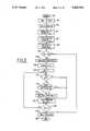
- steps 108, 110, 112, 114, 116, and 118a determination is made of exactly which power driver 12 1-8 has indicated a new fault, and the corresponding injector status counter (ISC 1-8 ) is updated. More specifically, index INJ is first set to 1 and the least significant bit (LSB) of register ISF 70 is compared to a logic 1 as shown by steps 108 and 110. Each affirmative comparison indicates that a new fault has occurred. The corresponding counter ISFC 1-8 is then checked for its maximum count (99 in this example) and incremented by 1 (see steps 112 and 114).
Landscapes
- Engineering & Computer Science (AREA)
- Computer Hardware Design (AREA)
- Microelectronics & Electronic Packaging (AREA)
- Chemical & Material Sciences (AREA)
- Combustion & Propulsion (AREA)
- Physics & Mathematics (AREA)
- General Physics & Mathematics (AREA)
- Combined Controls Of Internal Combustion Engines (AREA)
Abstract
Description
Claims (4)
Priority Applications (1)
| Application Number | Priority Date | Filing Date | Title |
|---|---|---|---|
| US07/396,206US5063516A (en) | 1989-08-21 | 1989-08-21 | Smart power driver system for a motor vehicle |
Applications Claiming Priority (1)
| Application Number | Priority Date | Filing Date | Title |
|---|---|---|---|
| US07/396,206US5063516A (en) | 1989-08-21 | 1989-08-21 | Smart power driver system for a motor vehicle |
Publications (1)
| Publication Number | Publication Date |
|---|---|
| US5063516Atrue US5063516A (en) | 1991-11-05 |
Family
ID=23566291
Family Applications (1)
| Application Number | Title | Priority Date | Filing Date |
|---|---|---|---|
| US07/396,206Expired - LifetimeUS5063516A (en) | 1989-08-21 | 1989-08-21 | Smart power driver system for a motor vehicle |
Country Status (1)
| Country | Link |
|---|---|
| US (1) | US5063516A (en) |
Cited By (28)
| Publication number | Priority date | Publication date | Assignee | Title |
|---|---|---|---|---|
| US5426589A (en)* | 1991-09-17 | 1995-06-20 | Honda Giken Kogyo Kabushiki Kaisha | Method of and apparatus for limiting electrical loads on an electric vehicle |
| US5430438A (en)* | 1990-02-22 | 1995-07-04 | Robert Bosch Gmbh | Method and device for functional monitoring of an electrical load |
| US5764653A (en)* | 1995-03-21 | 1998-06-09 | Sgs-Thomson Microelectronics S.A. | Method and apparatus for detecting abnormal operation in a storage circuit by monitoring an associated reference circuit |
| EP1052518A1 (en)* | 1999-05-13 | 2000-11-15 | STMicroelectronics S.r.l. | A system for the complete diagnosis of a driver |
| US6192302B1 (en) | 1998-07-31 | 2001-02-20 | Ford Global Technologies, Inc. | Motor vehicle diagnostic system and apparatus |
| US6320283B1 (en)* | 1999-09-10 | 2001-11-20 | Lockheed Martin Corporation | Power actuation and switching module |
| US6420877B1 (en)* | 1999-04-14 | 2002-07-16 | Group Dekko Services, Llc | Continuity totalizer/analyzer |
| US6484974B1 (en) | 2001-09-10 | 2002-11-26 | Union Switch & Signal, Inc. | Controller for switch machine |
| US20030074148A1 (en)* | 2001-10-17 | 2003-04-17 | Dvorak Robert F. | Arc fault circuit interrupter system |
| US20030072113A1 (en)* | 2001-10-17 | 2003-04-17 | Wong Kon B. | Arc detection using load recognition, harmonic content and broadband noise |
| US20030229664A1 (en)* | 2002-06-11 | 2003-12-11 | Hollaway Jerrell Penn | Maintainance support system for an electrical apparatus |
| WO2004031786A1 (en)* | 2002-09-25 | 2004-04-15 | Ballard Power Systems Ag | Circuit arrangement, in addition to method for identifying interruptions and short-circuits in coupled systems |
| WO2005012929A1 (en)* | 2003-07-31 | 2005-02-10 | Siemens Aktiengesellschaft | Method for the diagnosis of driver outputs and diagnosis pulse manager |
| WO2006102358A1 (en)* | 2005-03-22 | 2006-09-28 | Cummins, Inc. | Method and system for detecting faults in an electronic engine control module |
| US7136265B2 (en) | 2001-10-17 | 2006-11-14 | Square D Company | Load recognition and series arc detection using bandpass filter signatures |
| US20070146944A1 (en)* | 2005-12-27 | 2007-06-28 | General Protecht Group, Inc. | Apparatus and methods for testing the life of a leakage current protection device |
| US20070146945A1 (en)* | 2005-12-27 | 2007-06-28 | General Protecht Group, Inc. | Intelligent life testing methods and apparatus for leakage current protection device with indicating means |
| US7253637B2 (en) | 2005-09-13 | 2007-08-07 | Square D Company | Arc fault circuit interrupter system |
| US20070195470A1 (en)* | 2006-02-21 | 2007-08-23 | General Protecht Group, Inc. | Intelligent life testing methods and apparatus for leakage current protection |
| US7420791B1 (en)* | 2004-08-09 | 2008-09-02 | Intersil Americas Inc. | Fault signature system for power management integrated circuits |
| US20090168274A1 (en)* | 2007-12-27 | 2009-07-02 | Lear Corporation Gmbh | Method and system of providing overload and short-circuit protection for switched mode power supply |
| US20100082197A1 (en)* | 2008-09-30 | 2010-04-01 | Honeywell International Inc. | Intermittent fault detection and reasoning |
| US20110307209A1 (en)* | 2010-06-15 | 2011-12-15 | Timo Dittfeld | Diagnosis of Integrated Driver Circuits |
| US8977417B2 (en) | 2012-10-19 | 2015-03-10 | Ford Global Technologies, Llc | System and method for controlling a vehicle having a single-wire actuator |
| CN114275007A (en)* | 2022-01-21 | 2022-04-05 | 中国铁道科学研究院集团有限公司 | Fault determination device and method based on rail vehicle power module |
| US20220413225A1 (en)* | 2021-06-28 | 2022-12-29 | Google Llc | High Voltage Monitoring for Optical Switching Applications |
| CN116291831A (en)* | 2023-04-19 | 2023-06-23 | 卓品智能科技无锡股份有限公司 | Method and system for preventing false alarm of urea pump driving diagnosis fault |
| EP4492175A1 (en)* | 2023-07-12 | 2025-01-15 | Volvo Car Corporation | Computer-implemented method for providing data indicative of an intermittent failure for a vehicle |
Citations (11)
| Publication number | Priority date | Publication date | Assignee | Title |
|---|---|---|---|---|
| US4214308A (en)* | 1978-06-22 | 1980-07-22 | The Bendix Corporation | Closed loop sensor condition detector |
| US4412328A (en)* | 1981-02-04 | 1983-10-25 | The North American Manufacturing Company | Electromechanical device drive circuit fault detection apparatus |
| US4479161A (en)* | 1982-09-27 | 1984-10-23 | The Bendix Corporation | Switching type driver circuit for fuel injector |
| US4587615A (en)* | 1982-10-01 | 1986-05-06 | Fuji Jukogyo Kabushiki Kaisha | System for diagnosing an internal combustion engine |
| US4589401A (en)* | 1985-04-12 | 1986-05-20 | Motorola, Inc. | Injector driver fault detect and protection device |
| US4618954A (en)* | 1983-06-21 | 1986-10-21 | Honda Giken Kogyo Kabushiki Kaisha | Method of detecting abnormality in input and output units |
| US4635214A (en)* | 1983-06-30 | 1987-01-06 | Fujitsu Limited | Failure diagnostic processing system |
| US4736267A (en)* | 1986-11-14 | 1988-04-05 | Motorola, Inc. | Fault detection circuit |
| US4764884A (en)* | 1985-05-14 | 1988-08-16 | Suzuki Jidosha Kogyo Kabushiki Kaisha | Failure detecting apparatus of a control unit for a vehicle |
| US4821562A (en)* | 1986-04-03 | 1989-04-18 | Nissan Motor Company, Limited | Signal monitoring apparatus |
| US4932246A (en)* | 1989-02-22 | 1990-06-12 | Motorola, Inc. | Diagnostic fault test system and circuit |
- 1989
- 1989-08-21USUS07/396,206patent/US5063516A/ennot_activeExpired - Lifetime
Patent Citations (11)
| Publication number | Priority date | Publication date | Assignee | Title |
|---|---|---|---|---|
| US4214308A (en)* | 1978-06-22 | 1980-07-22 | The Bendix Corporation | Closed loop sensor condition detector |
| US4412328A (en)* | 1981-02-04 | 1983-10-25 | The North American Manufacturing Company | Electromechanical device drive circuit fault detection apparatus |
| US4479161A (en)* | 1982-09-27 | 1984-10-23 | The Bendix Corporation | Switching type driver circuit for fuel injector |
| US4587615A (en)* | 1982-10-01 | 1986-05-06 | Fuji Jukogyo Kabushiki Kaisha | System for diagnosing an internal combustion engine |
| US4618954A (en)* | 1983-06-21 | 1986-10-21 | Honda Giken Kogyo Kabushiki Kaisha | Method of detecting abnormality in input and output units |
| US4635214A (en)* | 1983-06-30 | 1987-01-06 | Fujitsu Limited | Failure diagnostic processing system |
| US4589401A (en)* | 1985-04-12 | 1986-05-20 | Motorola, Inc. | Injector driver fault detect and protection device |
| US4764884A (en)* | 1985-05-14 | 1988-08-16 | Suzuki Jidosha Kogyo Kabushiki Kaisha | Failure detecting apparatus of a control unit for a vehicle |
| US4821562A (en)* | 1986-04-03 | 1989-04-18 | Nissan Motor Company, Limited | Signal monitoring apparatus |
| US4736267A (en)* | 1986-11-14 | 1988-04-05 | Motorola, Inc. | Fault detection circuit |
| US4932246A (en)* | 1989-02-22 | 1990-06-12 | Motorola, Inc. | Diagnostic fault test system and circuit |
Non-Patent Citations (2)
| Title |
|---|
| Siemens, "SMT 12 SMART-SIPMOS® Intelligent Monolithic Power Switch", pp. 1-6, issued by Colorado Components Division, 10/85. |
| Siemens, SMT 12 SMART SIPMOS Intelligent Monolithic Power Switch , pp. 1 6, issued by Colorado Components Division, 10/85.* |
Cited By (42)
| Publication number | Priority date | Publication date | Assignee | Title |
|---|---|---|---|---|
| US5430438A (en)* | 1990-02-22 | 1995-07-04 | Robert Bosch Gmbh | Method and device for functional monitoring of an electrical load |
| US5426589A (en)* | 1991-09-17 | 1995-06-20 | Honda Giken Kogyo Kabushiki Kaisha | Method of and apparatus for limiting electrical loads on an electric vehicle |
| US5764653A (en)* | 1995-03-21 | 1998-06-09 | Sgs-Thomson Microelectronics S.A. | Method and apparatus for detecting abnormal operation in a storage circuit by monitoring an associated reference circuit |
| US6192302B1 (en) | 1998-07-31 | 2001-02-20 | Ford Global Technologies, Inc. | Motor vehicle diagnostic system and apparatus |
| US6420877B1 (en)* | 1999-04-14 | 2002-07-16 | Group Dekko Services, Llc | Continuity totalizer/analyzer |
| EP1052518A1 (en)* | 1999-05-13 | 2000-11-15 | STMicroelectronics S.r.l. | A system for the complete diagnosis of a driver |
| US6462557B1 (en) | 1999-05-13 | 2002-10-08 | Stmicroelectronics S.R.L. | System for the complete diagnosis of a driver |
| US6320283B1 (en)* | 1999-09-10 | 2001-11-20 | Lockheed Martin Corporation | Power actuation and switching module |
| US6484974B1 (en) | 2001-09-10 | 2002-11-26 | Union Switch & Signal, Inc. | Controller for switch machine |
| US7151656B2 (en) | 2001-10-17 | 2006-12-19 | Square D Company | Arc fault circuit interrupter system |
| US7068480B2 (en)* | 2001-10-17 | 2006-06-27 | Square D Company | Arc detection using load recognition, harmonic content and broadband noise |
| US20030072113A1 (en)* | 2001-10-17 | 2003-04-17 | Wong Kon B. | Arc detection using load recognition, harmonic content and broadband noise |
| US7136265B2 (en) | 2001-10-17 | 2006-11-14 | Square D Company | Load recognition and series arc detection using bandpass filter signatures |
| US20030074148A1 (en)* | 2001-10-17 | 2003-04-17 | Dvorak Robert F. | Arc fault circuit interrupter system |
| US20030229664A1 (en)* | 2002-06-11 | 2003-12-11 | Hollaway Jerrell Penn | Maintainance support system for an electrical apparatus |
| US6756907B2 (en)* | 2002-06-11 | 2004-06-29 | Jerrell Penn Hollaway | Maintainance support system for an electrical apparatus |
| US7340437B2 (en)* | 2002-09-25 | 2008-03-04 | Nucellsys Gmbh | Circuit configuration and method for identifying error situations in interconnected systems |
| WO2004031786A1 (en)* | 2002-09-25 | 2004-04-15 | Ballard Power Systems Ag | Circuit arrangement, in addition to method for identifying interruptions and short-circuits in coupled systems |
| US20060206762A1 (en)* | 2002-09-25 | 2006-09-14 | Markus Aberle | Circuit arrangement, in addition to method for identifying interruptions and short-circuits in coupled systems |
| WO2005012929A1 (en)* | 2003-07-31 | 2005-02-10 | Siemens Aktiengesellschaft | Method for the diagnosis of driver outputs and diagnosis pulse manager |
| US20060229795A1 (en)* | 2003-07-31 | 2006-10-12 | Siemens Aktengesellschaft | Method for the diagnosis of driver outputs and diagnosis pulse manager |
| US7420791B1 (en)* | 2004-08-09 | 2008-09-02 | Intersil Americas Inc. | Fault signature system for power management integrated circuits |
| WO2006102358A1 (en)* | 2005-03-22 | 2006-09-28 | Cummins, Inc. | Method and system for detecting faults in an electronic engine control module |
| US7253637B2 (en) | 2005-09-13 | 2007-08-07 | Square D Company | Arc fault circuit interrupter system |
| US20070146944A1 (en)* | 2005-12-27 | 2007-06-28 | General Protecht Group, Inc. | Apparatus and methods for testing the life of a leakage current protection device |
| US7522064B2 (en)* | 2005-12-27 | 2009-04-21 | General Protecht Group, Inc. | Apparatus and methods for testing the life of a leakage current protection device |
| US7525441B2 (en)* | 2005-12-27 | 2009-04-28 | General Protecht Group, Inc. | Intelligent life testing methods and apparatus for leakage current protection device with indicating means |
| US20070146945A1 (en)* | 2005-12-27 | 2007-06-28 | General Protecht Group, Inc. | Intelligent life testing methods and apparatus for leakage current protection device with indicating means |
| US7592924B2 (en)* | 2006-02-21 | 2009-09-22 | General Protecht Group, Inc. | Intelligent life testing methods and apparatus for leakage current protection |
| US20070195470A1 (en)* | 2006-02-21 | 2007-08-23 | General Protecht Group, Inc. | Intelligent life testing methods and apparatus for leakage current protection |
| US8050006B2 (en) | 2007-12-27 | 2011-11-01 | Lear Corporation Gmbh | Method and system of providing overload and short-circuit protection for switched mode power supply |
| US20090168274A1 (en)* | 2007-12-27 | 2009-07-02 | Lear Corporation Gmbh | Method and system of providing overload and short-circuit protection for switched mode power supply |
| US20100082197A1 (en)* | 2008-09-30 | 2010-04-01 | Honeywell International Inc. | Intermittent fault detection and reasoning |
| US20110307209A1 (en)* | 2010-06-15 | 2011-12-15 | Timo Dittfeld | Diagnosis of Integrated Driver Circuits |
| US9676357B2 (en)* | 2010-06-15 | 2017-06-13 | Infineon Technologies Ag | Diagnosis of integrated driver circuits |
| US8977417B2 (en) | 2012-10-19 | 2015-03-10 | Ford Global Technologies, Llc | System and method for controlling a vehicle having a single-wire actuator |
| US20220413225A1 (en)* | 2021-06-28 | 2022-12-29 | Google Llc | High Voltage Monitoring for Optical Switching Applications |
| US12235491B2 (en)* | 2021-06-28 | 2025-02-25 | Google Llc | High voltage monitoring for optical switching applications |
| CN114275007A (en)* | 2022-01-21 | 2022-04-05 | 中国铁道科学研究院集团有限公司 | Fault determination device and method based on rail vehicle power module |
| CN116291831A (en)* | 2023-04-19 | 2023-06-23 | 卓品智能科技无锡股份有限公司 | Method and system for preventing false alarm of urea pump driving diagnosis fault |
| CN116291831B (en)* | 2023-04-19 | 2023-10-10 | 卓品智能科技无锡股份有限公司 | Method and system for preventing false alarm of urea pump driving diagnosis fault |
| EP4492175A1 (en)* | 2023-07-12 | 2025-01-15 | Volvo Car Corporation | Computer-implemented method for providing data indicative of an intermittent failure for a vehicle |
Similar Documents
| Publication | Publication Date | Title |
|---|---|---|
| US5063516A (en) | Smart power driver system for a motor vehicle | |
| EP0477309B1 (en) | Device for monitoring the operation of an electrical consumer, its control and the associated connectors | |
| DE102004026114B4 (en) | Diagnostic systems and method for a device for detecting a leakage current | |
| KR890002531B1 (en) | Fault diagnosis processing system | |
| US5506772A (en) | Trouble-diagnosis multi-function tester | |
| DE3782165T3 (en) | SYSTEM FOR DETERMINING ANOMALIES AND FUNCTIONAL FAILURES OF DIFFERENT TYPES OF ELECTRONIC MONITORING SYSTEMS BUILT IN MOTOR VEHICLES. | |
| KR910002804B1 (en) | Multi-function testor for self-diagnosis | |
| EP0418665A1 (en) | Device for the detection and discrimination of functional faults in an electrical power supply circuit | |
| US4554461A (en) | Information transmitting apparatus | |
| JP4042467B2 (en) | Signal processing device | |
| US6664802B2 (en) | System and method for diagnosing fault conditions associated with powering an electrical load | |
| CN108844644A (en) | Battery temperature sampling system and car | |
| DE102006061523B4 (en) | Diagnostic procedure and diagnostic system and associated transducers | |
| US6023228A (en) | Method and apparatus for checking electrical drive mechanisms | |
| US6462557B1 (en) | System for the complete diagnosis of a driver | |
| EP1343086B1 (en) | Abnormality Detection Apparatus of Comparator | |
| GB2067307A (en) | Improvements in Apparatus for a Method of Diagnostic Testing of Electrically Controlled Machinery | |
| JP4394438B2 (en) | Apparatus and method for converting diagnostic interface to standard SPI | |
| DE102013105853A1 (en) | Information processing apparatus | |
| JP2621481B2 (en) | Drive circuit diagnostic method | |
| US6367028B1 (en) | Self diagnosing communications bus and method of operating same | |
| CN87108371A (en) | Computer-aided probe with tri-state circuitry test capability | |
| EP2212788A1 (en) | Method for operating an electronic device | |
| KR100192423B1 (en) | Fault Judgment Control Method of Actuator | |
| JP2639103B2 (en) | Failure diagnosis device for automotive electronic control unit |
Legal Events
| Date | Code | Title | Description |
|---|---|---|---|
| AS | Assignment | Owner name:FORD MOTOR COMPANY, MICHIGAN Free format text:ASSIGNMENT OF ASSIGNORS INTEREST.;ASSIGNOR:HECK, KARL R.;REEL/FRAME:005182/0889 Effective date:19890811 Owner name:FORD MOTOR COMPANY, MICHIGAN Free format text:ASSIGNMENT OF ASSIGNORS INTEREST.;ASSIGNORS:JAMOUA, SAAD A.;SARNOWSKY, MELVIN J.;REEL/FRAME:005182/0890 Effective date:19890815 | |
| STCF | Information on status: patent grant | Free format text:PATENTED CASE | |
| FPAY | Fee payment | Year of fee payment:4 | |
| REFU | Refund | Free format text:REFUND - PAYMENT OF MAINTENANCE FEE, 8TH YEAR, LARGE ENTITY (ORIGINAL EVENT CODE: R184); ENTITY STATUS OF PATENT OWNER: LARGE ENTITY | |
| FPAY | Fee payment | Year of fee payment:8 | |
| AS | Assignment | Owner name:FORD GLOBAL TECHNOLOGIES, INC. A MICHIGAN CORPORAT Free format text:ASSIGNMENT OF ASSIGNORS INTEREST;ASSIGNOR:FORD MOTOR COMPANY, A DELAWARE CORPORATION;REEL/FRAME:011467/0001 Effective date:19970301 | |
| FPAY | Fee payment | Year of fee payment:12 |