US5063351A - Digital signal processing relating to near-end crosstalk cable measurements - Google Patents
Digital signal processing relating to near-end crosstalk cable measurementsDownload PDFInfo
- Publication number
- US5063351A US5063351AUS07/587,241US58724190AUS5063351AUS 5063351 AUS5063351 AUS 5063351AUS 58724190 AUS58724190 AUS 58724190AUS 5063351 AUS5063351 AUS 5063351A
- Authority
- US
- United States
- Prior art keywords
- circuitry
- recited
- sequence
- filter
- wires
- Prior art date
- Legal status (The legal status is an assumption and is not a legal conclusion. Google has not performed a legal analysis and makes no representation as to the accuracy of the status listed.)
- Expired - Lifetime
Links
- 238000005259measurementMethods0.000titledescription12
- 238000012545processingMethods0.000titledescription12
- 230000003595spectral effectEffects0.000claimsabstractdescription26
- 230000002452interceptive effectEffects0.000claimsabstractdescription22
- 238000012360testing methodMethods0.000claimsabstractdescription20
- 238000004891communicationMethods0.000claimsabstractdescription4
- 230000009466transformationEffects0.000claimsdescription14
- 230000006870functionEffects0.000claimsdescription13
- 238000012546transferMethods0.000claimsdescription12
- 238000001228spectrumMethods0.000claimsdescription7
- 238000001914filtrationMethods0.000claimsdescription5
- 230000001131transforming effectEffects0.000claims8
- 230000008878couplingEffects0.000abstractdescription18
- 238000010168coupling processMethods0.000abstractdescription18
- 238000005859coupling reactionMethods0.000abstractdescription18
- 230000002301combined effectEffects0.000abstractdescription3
- 238000000034methodMethods0.000description13
- 238000010586diagramMethods0.000description11
- 230000005540biological transmissionEffects0.000description9
- 238000007493shaping processMethods0.000description4
- 239000011230binding agentSubstances0.000description3
- 238000004088simulationMethods0.000description3
- 238000013459approachMethods0.000description2
- 238000006243chemical reactionMethods0.000description2
- 238000005094computer simulationMethods0.000description2
- 230000006735deficitEffects0.000description2
- 238000013461designMethods0.000description2
- 230000000694effectsEffects0.000description2
- 230000007246mechanismEffects0.000description2
- 230000008569processEffects0.000description2
- 238000012795verificationMethods0.000description2
- 238000010420art techniqueMethods0.000description1
- 230000008901benefitEffects0.000description1
- 238000007796conventional methodMethods0.000description1
- 230000002596correlated effectEffects0.000description1
- 230000000875corresponding effectEffects0.000description1
- 230000007812deficiencyEffects0.000description1
- 238000005516engineering processMethods0.000description1
- 238000011835investigationMethods0.000description1
- 238000000691measurement methodMethods0.000description1
- 230000008520organizationEffects0.000description1
- 230000000644propagated effectEffects0.000description1
- 238000013139quantizationMethods0.000description1
- 230000004044responseEffects0.000description1
- 238000005070samplingMethods0.000description1
- 239000004065semiconductorSubstances0.000description1
Images


Classifications
- H—ELECTRICITY
- H04—ELECTRIC COMMUNICATION TECHNIQUE
- H04B—TRANSMISSION
- H04B3/00—Line transmission systems
- H04B3/02—Details
- H04B3/46—Monitoring; Testing
- H04B3/487—Testing crosstalk effects
Definitions
- NEXT for a system-under-testwhich utilizes a selected set of wires
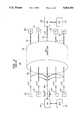
- circuitrythat includes: a digital noise generator for producing a stream of white, Gaussian-distributed discretized noise samples; and digital filter means for processing the noise samples to produce a signal which can be coupled to the selected set of wires used by the SUT.
- the frequency characteristic of the digital filtercorresponds to the combined spectral content of the interfering sources as well as the NEXT path coupling the interfering sources to the selected set of wires as inferred from actual cable measurements and modeled in the frequency domain.
- the output of the digital filterafter conversion to analog form, is injected into the selected set of wires at a prescribed location, typically the input the receiver of the SUT.
- This suggested techniqueavoids many of the problems of the "barrage testing" technique.
- the methodis less hardware intensive.
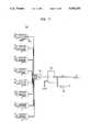
- a new NEXT environmentcan be obtained merely by incorporating another transmitter filter 215.
- BERBit Error Rate
- an explicit measurement of the NEXT marginis obtained.
- use of a hardware realization of the 1% NEXT transfer function in place of a small sample of crosstalk configurationsgives the data statistical meaning.
- this second techniquestill has its shortcomings since it lacks the flexibility to perform a variety of measurements.
- One major limitationis the use of analog filtering to generate the NEXT interference. The complex analog filters required are not presently available to match the variety of systems to be tested.
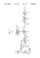
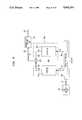
- the complete signal processing required to filter the noise samples from generator 310 into a discretized replica of NEXT for a particular systemis performed by DSP 340; this means that the processing formerly implemented by two distinct analog filters in cascade can readily be effected by just one digital signal processing stage.
- the overall spectral characteristic required of this digital processing stageis representative of the combined effect of the interfering source spectral shaping and the NEXT spectral shaping.
- an exemplary "template" for the spectral content of one type of signal formatis depicted in FIG. 4.
- the energy in the exemplary signalcovers the range from DC to about 160 kHz.
- the NEXT transfer function for three interfering conditionsis shown in FIG.
- the output power of line driver 370is determined by: (i) measuring the transmit power spectral density of the exemplary system; (ii) calculating the 1% NEXT power spectral density of the exemplary system, and (iii) calculating the power sum of this 1% NEXT power spectral density. For the exemplary system, this process yields a NEXT power of -57 dBm.
Landscapes
- Engineering & Computer Science (AREA)
- Computer Networks & Wireless Communication (AREA)
- Signal Processing (AREA)
- Cable Transmission Systems, Equalization Of Radio And Reduction Of Echo (AREA)
Abstract
Description
TABLE I ______________________________________ Coefficient Unscaled Value ______________________________________ 1 -8 2 -106 3 -10 4 -459 5 -81 6 -12694 7 390 8 28164 9 390 10 -12694 11 -81 12 -459 13 -10 14 -106 15 -8 ______________________________________
TABLE II ______________________________________ R.sub.A R.sub.B Coupling loss ______________________________________ 2860 1000 15.92 1971 1500 19.35 1702 2000 21.80 1572 2500 23.71 1496 3000 25.27 ______________________________________
Claims (18)
Priority Applications (1)
| Application Number | Priority Date | Filing Date | Title |
|---|---|---|---|
| US07/587,241US5063351A (en) | 1990-09-24 | 1990-09-24 | Digital signal processing relating to near-end crosstalk cable measurements |
Applications Claiming Priority (1)
| Application Number | Priority Date | Filing Date | Title |
|---|---|---|---|
| US07/587,241US5063351A (en) | 1990-09-24 | 1990-09-24 | Digital signal processing relating to near-end crosstalk cable measurements |
Publications (1)
| Publication Number | Publication Date |
|---|---|
| US5063351Atrue US5063351A (en) | 1991-11-05 |
Family
ID=24348982
Family Applications (1)
| Application Number | Title | Priority Date | Filing Date |
|---|---|---|---|
| US07/587,241Expired - LifetimeUS5063351A (en) | 1990-09-24 | 1990-09-24 | Digital signal processing relating to near-end crosstalk cable measurements |
Country Status (1)
| Country | Link |
|---|---|
| US (1) | US5063351A (en) |
Cited By (30)
| Publication number | Priority date | Publication date | Assignee | Title |
|---|---|---|---|---|
| US5436953A (en)* | 1993-07-02 | 1995-07-25 | Northern Telecom Limited | Digital longitudinal balance measurement |
| US5475315A (en)* | 1991-09-20 | 1995-12-12 | Audio Precision, Inc. | Method and apparatus for fast response and distortion measurement |
| US5532603A (en)* | 1995-01-27 | 1996-07-02 | Fluke Corporation | Cross-talk measurement apparatus with near-end compensation |
| US5570029A (en)* | 1994-03-30 | 1996-10-29 | Fluke Corporation | Cable crosstalk measurement system |
| US5633801A (en)* | 1995-10-11 | 1997-05-27 | Fluke Corporation | Pulse-based impedance measurement instrument |
| US5821760A (en)* | 1996-07-31 | 1998-10-13 | Fluke Corporation | Method and apparatus for measuring near-end cross-talk in patch cords |
| US6226356B1 (en)* | 1998-06-12 | 2001-05-01 | Legerity Inc. | Method and apparatus for power regulation of digital data transmission |
| US6229855B1 (en)* | 1996-09-03 | 2001-05-08 | Adc Telecommunications, Inc. | Adaptive transmitter for digital transmission |
| WO2001035607A1 (en)* | 1999-11-11 | 2001-05-17 | Voyan Technology | Design and architecture of an impairment diagnosis system for use in communications systems |
| US6292559B1 (en) | 1997-12-19 | 2001-09-18 | Rice University | Spectral optimization and joint signaling techniques with upstream/downstream separation for communication in the presence of crosstalk |
| US6381269B1 (en)* | 1999-05-28 | 2002-04-30 | Lucent Technologies Inc. | Test system with signal injection network for characterizing interference and noise tolerance in a digital signal link |
| US20020120898A1 (en)* | 2001-02-28 | 2002-08-29 | International Business Machines Corporaton | Digital random noise generator |
| US6834109B1 (en) | 1999-11-11 | 2004-12-21 | Tokyo Electron Limited | Method and apparatus for mitigation of disturbers in communication systems |
| US6867766B1 (en)* | 1999-05-25 | 2005-03-15 | Sony Computer Entertainment Inc. | Image generating apparatus, image generating method, entertainment system, and recording medium |
| US6870901B1 (en) | 1999-11-11 | 2005-03-22 | Tokyo Electron Limited | Design and architecture of an impairment diagnosis system for use in communications systems |
| US6970415B1 (en) | 1999-11-11 | 2005-11-29 | Tokyo Electron Limited | Method and apparatus for characterization of disturbers in communication systems |
| US6970560B1 (en) | 1999-11-11 | 2005-11-29 | Tokyo Electron Limited | Method and apparatus for impairment diagnosis in communication systems |
| US6978015B1 (en) | 1999-11-11 | 2005-12-20 | Tokyo Electron Limited | Method and apparatus for cooperative diagnosis of impairments and mitigation of disturbers in communication systems |
| US6999504B1 (en) | 2000-11-21 | 2006-02-14 | Globespanvirata, Inc. | System and method for canceling crosstalk |
| US7035400B1 (en) | 1999-03-01 | 2006-04-25 | Wm. Marsh Rice University | Signaling Techniques in channels with asymmetric powers and capacities |
| US20080144484A1 (en)* | 2005-02-16 | 2008-06-19 | Eci Telecom Ltd. | Method and Device for Connecting an Additional Subscriber to a Telephone Exchange |
| US20080273638A1 (en)* | 2007-05-04 | 2008-11-06 | Conexant Systems, Inc. | Reducing the Effect of Noise in a Multi-Channel Telecommunication Receiver |
| US20080291897A1 (en)* | 2005-11-01 | 2008-11-27 | Eci Telecom Ltd. | Access System for the Provisioning of Different Communications Sevices, and Method for Using Same |
| US20090141644A1 (en)* | 2007-11-30 | 2009-06-04 | Ploumen Franciscus M | Twisted pair cable plant cross talk coupling simulator |
| US7864692B1 (en) | 1999-11-11 | 2011-01-04 | Tokyo Electron Limited | Method and apparatus for the prediction and optimization in impaired communication systems |
| US20130177155A1 (en)* | 2012-10-05 | 2013-07-11 | Comtech Ef Data Corp. | Method and System for Generating Normal Distributed Random Variables Based On Cryptographic Function |
| WO2015039289A1 (en)* | 2013-09-17 | 2015-03-26 | 华为技术有限公司 | Method, device and system for detecting disturbing line |
| US20150095274A1 (en)* | 2013-10-02 | 2015-04-02 | Qualcomm Incorporated | Method and apparatus for producing programmable probability distribution function of pseudo-random numbers |
| US9106286B2 (en) | 2000-06-13 | 2015-08-11 | Comcast Cable Communications, Llc | Network communication using diversity |
| CN106774624A (en)* | 2016-11-24 | 2017-05-31 | 北京理工大学 | A kind of Parallel Implementation method of real-time white Gaussian noise hardware generator |
Citations (5)
| Publication number | Priority date | Publication date | Assignee | Title |
|---|---|---|---|---|
| US3471779A (en)* | 1964-09-25 | 1969-10-07 | Solartron Electronic Group | Method and apparatus for testing dynamic response using chain code input function |
| US3718813A (en)* | 1972-01-19 | 1973-02-27 | O Williams | Technique for correlation method of determining system impulse response |
| US3988667A (en)* | 1975-03-06 | 1976-10-26 | Hewlett-Packard Company | Noise source for transfer function testing |
| US4023098A (en)* | 1975-08-27 | 1977-05-10 | Hewlett-Packard Company | Noise burst source for transfer function testing |
| US4973911A (en)* | 1988-02-19 | 1990-11-27 | Marshall Richard C | Apparatus for electromagnetic compatibility testing |
- 1990
- 1990-09-24USUS07/587,241patent/US5063351A/ennot_activeExpired - Lifetime
Patent Citations (5)
| Publication number | Priority date | Publication date | Assignee | Title |
|---|---|---|---|---|
| US3471779A (en)* | 1964-09-25 | 1969-10-07 | Solartron Electronic Group | Method and apparatus for testing dynamic response using chain code input function |
| US3718813A (en)* | 1972-01-19 | 1973-02-27 | O Williams | Technique for correlation method of determining system impulse response |
| US3988667A (en)* | 1975-03-06 | 1976-10-26 | Hewlett-Packard Company | Noise source for transfer function testing |
| US4023098A (en)* | 1975-08-27 | 1977-05-10 | Hewlett-Packard Company | Noise burst source for transfer function testing |
| US4973911A (en)* | 1988-02-19 | 1990-11-27 | Marshall Richard C | Apparatus for electromagnetic compatibility testing |
Non-Patent Citations (6)
| Title |
|---|
| "Near-End Crosstalk Model For Line Code Studies", Bell Communications Research, Inc., T1D1.3 Contribution 85-244, Nov. 12,1985. |
| "Suggested Testing Plan to Determine Line Code Performance", Bell Communications Research, Inc., T1D1.3 Contribution 86-095, Jun. 9, 1986. |
| Hewlett Packard 1983 Catalog pp. 508 510 Model 3582A Analyzer.* |
| Hewlett-Packard-1983 Catalog-pp. 508-510-Model 3582A Analyzer. |
| Near End Crosstalk Model For Line Code Studies , Bell Communications Research, Inc., T1D1.3 Contribution 85 244, Nov. 12,1985.* |
| Suggested Testing Plan to Determine Line Code Performance , Bell Communications Research, Inc., T1D1.3 Contribution 86 095, Jun. 9, 1986.* |
Cited By (54)
| Publication number | Priority date | Publication date | Assignee | Title |
|---|---|---|---|---|
| US5475315A (en)* | 1991-09-20 | 1995-12-12 | Audio Precision, Inc. | Method and apparatus for fast response and distortion measurement |
| US5436953A (en)* | 1993-07-02 | 1995-07-25 | Northern Telecom Limited | Digital longitudinal balance measurement |
| US5570029A (en)* | 1994-03-30 | 1996-10-29 | Fluke Corporation | Cable crosstalk measurement system |
| EP0675607A3 (en)* | 1994-03-30 | 1997-05-21 | Fluke Corp | Cable crosstalk measurement system. |
| US5532603A (en)* | 1995-01-27 | 1996-07-02 | Fluke Corporation | Cross-talk measurement apparatus with near-end compensation |
| US5633801A (en)* | 1995-10-11 | 1997-05-27 | Fluke Corporation | Pulse-based impedance measurement instrument |
| US5821760A (en)* | 1996-07-31 | 1998-10-13 | Fluke Corporation | Method and apparatus for measuring near-end cross-talk in patch cords |
| US6229855B1 (en)* | 1996-09-03 | 2001-05-08 | Adc Telecommunications, Inc. | Adaptive transmitter for digital transmission |
| US6292559B1 (en) | 1997-12-19 | 2001-09-18 | Rice University | Spectral optimization and joint signaling techniques with upstream/downstream separation for communication in the presence of crosstalk |
| US6839429B1 (en) | 1997-12-19 | 2005-01-04 | Wm. Marsh Rice University | Spectral optimization for communication under a peak frequency-domain power constraint |
| US6317495B1 (en) | 1997-12-19 | 2001-11-13 | Wm. Marsh Rice University | Spectral optimization and joint signaling techniques with multi-line separation for communication in the presence of crosstalk |
| US6226356B1 (en)* | 1998-06-12 | 2001-05-01 | Legerity Inc. | Method and apparatus for power regulation of digital data transmission |
| US7035400B1 (en) | 1999-03-01 | 2006-04-25 | Wm. Marsh Rice University | Signaling Techniques in channels with asymmetric powers and capacities |
| US6867766B1 (en)* | 1999-05-25 | 2005-03-15 | Sony Computer Entertainment Inc. | Image generating apparatus, image generating method, entertainment system, and recording medium |
| US6381269B1 (en)* | 1999-05-28 | 2002-04-30 | Lucent Technologies Inc. | Test system with signal injection network for characterizing interference and noise tolerance in a digital signal link |
| US6834109B1 (en) | 1999-11-11 | 2004-12-21 | Tokyo Electron Limited | Method and apparatus for mitigation of disturbers in communication systems |
| WO2001035607A1 (en)* | 1999-11-11 | 2001-05-17 | Voyan Technology | Design and architecture of an impairment diagnosis system for use in communications systems |
| US6870901B1 (en) | 1999-11-11 | 2005-03-22 | Tokyo Electron Limited | Design and architecture of an impairment diagnosis system for use in communications systems |
| US7864692B1 (en) | 1999-11-11 | 2011-01-04 | Tokyo Electron Limited | Method and apparatus for the prediction and optimization in impaired communication systems |
| US6970415B1 (en) | 1999-11-11 | 2005-11-29 | Tokyo Electron Limited | Method and apparatus for characterization of disturbers in communication systems |
| US6970560B1 (en) | 1999-11-11 | 2005-11-29 | Tokyo Electron Limited | Method and apparatus for impairment diagnosis in communication systems |
| US6978015B1 (en) | 1999-11-11 | 2005-12-20 | Tokyo Electron Limited | Method and apparatus for cooperative diagnosis of impairments and mitigation of disturbers in communication systems |
| US9197297B2 (en) | 2000-06-13 | 2015-11-24 | Comcast Cable Communications, Llc | Network communication using diversity |
| US9401783B1 (en) | 2000-06-13 | 2016-07-26 | Comcast Cable Communications, Llc | Transmission of data to multiple nodes |
| US10349332B2 (en) | 2000-06-13 | 2019-07-09 | Comcast Cable Communications, Llc | Network communication using selected resources |
| US10257765B2 (en) | 2000-06-13 | 2019-04-09 | Comcast Cable Communications, Llc | Transmission of OFDM symbols |
| US9820209B1 (en) | 2000-06-13 | 2017-11-14 | Comcast Cable Communications, Llc | Data routing for OFDM transmissions |
| US9722842B2 (en) | 2000-06-13 | 2017-08-01 | Comcast Cable Communications, Llc | Transmission of data using a plurality of radio frequency channels |
| US9654323B2 (en) | 2000-06-13 | 2017-05-16 | Comcast Cable Communications, Llc | Data routing for OFDM transmission based on observed node capacities |
| US9515788B2 (en) | 2000-06-13 | 2016-12-06 | Comcast Cable Communications, Llc | Originator and recipient based transmissions in wireless communications |
| US9391745B2 (en) | 2000-06-13 | 2016-07-12 | Comcast Cable Communications, Llc | Multi-user transmissions |
| US9356666B1 (en) | 2000-06-13 | 2016-05-31 | Comcast Cable Communications, Llc | Originator and recipient based transmissions in wireless communications |
| US9344233B2 (en) | 2000-06-13 | 2016-05-17 | Comcast Cable Communications, Llc | Originator and recipient based transmissions in wireless communications |
| US9209871B2 (en) | 2000-06-13 | 2015-12-08 | Comcast Cable Communications, Llc | Network communication using diversity |
| USRE45807E1 (en) | 2000-06-13 | 2015-11-17 | Comcast Cable Communications, Llc | Apparatus for transmitting a signal including transmit data to a multiple-input capable node |
| USRE45775E1 (en) | 2000-06-13 | 2015-10-20 | Comcast Cable Communications, Llc | Method and system for robust, secure, and high-efficiency voice and packet transmission over ad-hoc, mesh, and MIMO communication networks |
| US9106286B2 (en) | 2000-06-13 | 2015-08-11 | Comcast Cable Communications, Llc | Network communication using diversity |
| US6999504B1 (en) | 2000-11-21 | 2006-02-14 | Globespanvirata, Inc. | System and method for canceling crosstalk |
| US20020120898A1 (en)* | 2001-02-28 | 2002-08-29 | International Business Machines Corporaton | Digital random noise generator |
| US6910165B2 (en)* | 2001-02-28 | 2005-06-21 | International Business Machines Corporation | Digital random noise generator |
| US20080144484A1 (en)* | 2005-02-16 | 2008-06-19 | Eci Telecom Ltd. | Method and Device for Connecting an Additional Subscriber to a Telephone Exchange |
| US20080291897A1 (en)* | 2005-11-01 | 2008-11-27 | Eci Telecom Ltd. | Access System for the Provisioning of Different Communications Sevices, and Method for Using Same |
| US8369426B2 (en) | 2007-05-04 | 2013-02-05 | Ikanos Communications, Inc. | Reducing the effect of noise in a multi-channel telecommunication receiver |
| US20080273638A1 (en)* | 2007-05-04 | 2008-11-06 | Conexant Systems, Inc. | Reducing the Effect of Noise in a Multi-Channel Telecommunication Receiver |
| WO2009073528A1 (en)* | 2007-11-30 | 2009-06-11 | Alcatel Lucent | Crosstalk coupling simulator |
| US8270287B2 (en) | 2007-11-30 | 2012-09-18 | Alcatel Lucent | Twisted pair cable plant cross talk coupling simulator |
| US20090141644A1 (en)* | 2007-11-30 | 2009-06-04 | Ploumen Franciscus M | Twisted pair cable plant cross talk coupling simulator |
| US20130177155A1 (en)* | 2012-10-05 | 2013-07-11 | Comtech Ef Data Corp. | Method and System for Generating Normal Distributed Random Variables Based On Cryptographic Function |
| WO2015039289A1 (en)* | 2013-09-17 | 2015-03-26 | 华为技术有限公司 | Method, device and system for detecting disturbing line |
| CN104641567B (en)* | 2013-09-17 | 2016-08-17 | 华为技术有限公司 | A method, device and system for detecting interference lines |
| CN104641567A (en)* | 2013-09-17 | 2015-05-20 | 华为技术有限公司 | Method, device and system for detecting disturbing line |
| US9417845B2 (en)* | 2013-10-02 | 2016-08-16 | Qualcomm Incorporated | Method and apparatus for producing programmable probability distribution function of pseudo-random numbers |
| US20150095274A1 (en)* | 2013-10-02 | 2015-04-02 | Qualcomm Incorporated | Method and apparatus for producing programmable probability distribution function of pseudo-random numbers |
| CN106774624A (en)* | 2016-11-24 | 2017-05-31 | 北京理工大学 | A kind of Parallel Implementation method of real-time white Gaussian noise hardware generator |
Similar Documents
| Publication | Publication Date | Title |
|---|---|---|
| US5063351A (en) | Digital signal processing relating to near-end crosstalk cable measurements | |
| US6934655B2 (en) | Method and apparatus for transmission line analysis | |
| Degardin et al. | Classification and characterization of impulsive noise on indoor powerline used for data communications | |
| US8650010B2 (en) | Apparatus and method for generating a test signal with emulated crosstalk | |
| US6885954B2 (en) | Sequence time domain reflectometry using complementary golay codes | |
| US6526365B1 (en) | Low-power/wideband transfer function measurement method and apparatus | |
| Artale et al. | A line impedance calculator based on a G3 PLC modem platform | |
| JPWO2007116765A1 (en) | Test apparatus and test method | |
| CA1096507A (en) | Modified duobinary regenerative repeater testing arrangement | |
| Yeap et al. | A novel common-mode noise cancellation technique for VDSL applications | |
| CN211860117U (en) | A Communication Test Experiment Platform for Electric Energy Metering Equipment | |
| Liu et al. | Advanced emulation of channel transfer functions for performance evaluation of powerline modems | |
| Abinaya et al. | Design & analysis of line impedance stabilization network using RLC components for ITE | |
| Dixon et al. | NEXTNOIS-a programmable noise generating system for testing wire-based loop transmission systems | |
| Dulay et al. | FPGA implementation of an indoor broadband power line channel emulator | |
| Bausch et al. | Advanced" Orphelec" test equipment and novel test procedures | |
| CN103227763A (en) | Variable inter symbol interference generator | |
| Sehlstedt | RFI cancellation in VDSL | |
| EP1095480A1 (en) | Adsl test system | |
| Rahman et al. | The Analytical Approach to Evaluate the Bit Error Rate Performance of PLC System in Presence of Cyclostationary Non-White Gaussian Noise | |
| Chiu et al. | Loop survey in the Taiwan area and feasibility study for HDSL | |
| CN113783633A (en) | Multi-band noise simulation device and method | |
| Charles et al. | A Power Line Communications System Based on Discrete Multi-Tone Modulation | |
| Snyders et al. | The impact of coupling/filtering on orthogonal M-FSK | |
| Chen et al. | Development and application on amplitude-frequency characteristic detection instrument of filter |
Legal Events
| Date | Code | Title | Description |
|---|---|---|---|
| AS | Assignment | Owner name:BELL COMMUNICATIONS RESEARCH, INC. A CORPORATION Free format text:ASSIGNMENT OF ASSIGNORS INTEREST.;ASSIGNORS:GOLDTHORP, JEFFERY M.;YEOMANS, JAMES S.;REEL/FRAME:005765/0009 Effective date:19900924 | |
| STCF | Information on status: patent grant | Free format text:PATENTED CASE | |
| FEPP | Fee payment procedure | Free format text:PAYOR NUMBER ASSIGNED (ORIGINAL EVENT CODE: ASPN); ENTITY STATUS OF PATENT OWNER: LARGE ENTITY | |
| FPAY | Fee payment | Year of fee payment:4 | |
| FPAY | Fee payment | Year of fee payment:8 | |
| AS | Assignment | Owner name:TELCORDIA TECHNOLOGIES, INC., NEW JERSEY Free format text:CHANGE OF NAME;ASSIGNOR:BELL COMMUNICATIONS RESEARCH, INC.;REEL/FRAME:010263/0311 Effective date:19990316 | |
| FPAY | Fee payment | Year of fee payment:12 | |
| AS | Assignment | Owner name:JPMORGAN CHASE BANK, N.A., AS ADMINISTRATIVE AGENT Free format text:SECURITY AGREEMENT;ASSIGNOR:TELCORDIA TECHNOLOGIES, INC.;REEL/FRAME:015886/0001 Effective date:20050315 | |
| AS | Assignment | Owner name:TELCORDIA TECHNOLOGIES, INC., NEW JERSEY Free format text:TERMINATION AND RELEASE OF SECURITY INTEREST IN PATENT RIGHTS;ASSIGNOR:JPMORGAN CHASE BANK, N.A., AS ADMINISTRATIVE AGENT;REEL/FRAME:019520/0174 Effective date:20070629 Owner name:TELCORDIA TECHNOLOGIES, INC.,NEW JERSEY Free format text:TERMINATION AND RELEASE OF SECURITY INTEREST IN PATENT RIGHTS;ASSIGNOR:JPMORGAN CHASE BANK, N.A., AS ADMINISTRATIVE AGENT;REEL/FRAME:019520/0174 Effective date:20070629 | |
| AS | Assignment | Owner name:WILMINGTON TRUST COMPANY, AS COLLATERAL AGENT, DEL Free format text:SECURITY AGREEMENT;ASSIGNOR:TELCORDIA TECHNOLOGIES, INC.;REEL/FRAME:019562/0309 Effective date:20070629 Owner name:WILMINGTON TRUST COMPANY, AS COLLATERAL AGENT,DELA Free format text:SECURITY AGREEMENT;ASSIGNOR:TELCORDIA TECHNOLOGIES, INC.;REEL/FRAME:019562/0309 Effective date:20070629 | |
| FEPP | Fee payment procedure | Free format text:PAYER NUMBER DE-ASSIGNED (ORIGINAL EVENT CODE: RMPN); ENTITY STATUS OF PATENT OWNER: LARGE ENTITY Free format text:PAYOR NUMBER ASSIGNED (ORIGINAL EVENT CODE: ASPN); ENTITY STATUS OF PATENT OWNER: LARGE ENTITY | |
| AS | Assignment | Owner name:TELCORDIA TECHNOLOGIES, INC., NEW JERSEY Free format text:RELEASE OF SECURITY INTEREST;ASSIGNOR:WILMINGTON TRUST COMPANY;REEL/FRAME:022408/0410 Effective date:20090220 Owner name:TELCORDIA TECHNOLOGIES, INC.,NEW JERSEY Free format text:RELEASE OF SECURITY INTEREST;ASSIGNOR:WILMINGTON TRUST COMPANY;REEL/FRAME:022408/0410 Effective date:20090220 | |
| AS | Assignment | Owner name:TELCORDIA LICENSING COMPANY LLC, NEW JERSEY Free format text:ASSIGNMENT OF ASSIGNORS INTEREST;ASSIGNOR:TELCORDIA TECHNOLOGIES, INC.;REEL/FRAME:022878/0821 Effective date:20090616 | |
| AS | Assignment | Owner name:TELCORDIA TECHNOLOGIES, INC.,NEW JERSEY Free format text:RELEASE;ASSIGNOR:WILMINGTON TRUST COMPANY, AS COLLATERAL AGENT;REEL/FRAME:024515/0622 Effective date:20100430 Owner name:TELCORDIA TECHNOLOGIES, INC., NEW JERSEY Free format text:RELEASE;ASSIGNOR:WILMINGTON TRUST COMPANY, AS COLLATERAL AGENT;REEL/FRAME:024515/0622 Effective date:20100430 | |
| AS | Assignment | Owner name:TTI INVENTIONS B LLC, DELAWARE Free format text:ASSIGNMENT OF ASSIGNORS INTEREST;ASSIGNOR:TELCORDIA LICENSING COMPANY, LLC;REEL/FRAME:027532/0110 Effective date:20111102 |