US5062852A - Tibial prosthesis with independent medial and lateral baseplates - Google Patents
Tibial prosthesis with independent medial and lateral baseplatesDownload PDFInfo
- Publication number
- US5062852A US5062852AUS07/477,745US47774590AUS5062852AUS 5062852 AUS5062852 AUS 5062852AUS 47774590 AUS47774590 AUS 47774590AUS 5062852 AUS5062852 AUS 5062852A
- Authority
- US
- United States
- Prior art keywords
- baseplate
- tibial prosthesis
- prosthesis according
- tibia
- baseplates
- Prior art date
- Legal status (The legal status is an assumption and is not a legal conclusion. Google has not performed a legal analysis and makes no representation as to the accuracy of the status listed.)
- Expired - Lifetime
Links
- 210000002303tibiaAnatomy0.000claimsabstractdescription60
- 238000002513implantationMethods0.000claimsabstractdescription18
- 238000000034methodMethods0.000claimsdescription11
- 239000007943implantSubstances0.000claimsdescription4
- 210000003127kneeAnatomy0.000claimsdescription4
- 238000003801millingMethods0.000claimsdescription2
- 239000004705High-molecular-weight polyethyleneSubstances0.000abstractdescription3
- 230000003292diminished effectEffects0.000abstractdescription2
- 210000000988bone and boneAnatomy0.000description23
- 230000001054cortical effectEffects0.000description5
- 210000000689upper legAnatomy0.000description4
- 201000010099diseaseDiseases0.000description3
- 208000037265diseases, disorders, signs and symptomsDiseases0.000description3
- 230000033001locomotionEffects0.000description3
- 230000007774longtermEffects0.000description3
- 230000009471actionEffects0.000description2
- 230000032683agingEffects0.000description2
- 230000000694effectsEffects0.000description2
- 210000000629knee jointAnatomy0.000description2
- 210000003041ligamentAnatomy0.000description2
- 229910052751metalInorganic materials0.000description2
- 239000002184metalSubstances0.000description2
- RTAQQCXQSZGOHL-UHFFFAOYSA-NTitaniumChemical compound[Ti]RTAQQCXQSZGOHL-UHFFFAOYSA-N0.000description1
- 239000004699Ultra-high molecular weight polyethyleneSubstances0.000description1
- 239000002639bone cementSubstances0.000description1
- 230000008468bone growthEffects0.000description1
- 230000015556catabolic processEffects0.000description1
- 230000008859changeEffects0.000description1
- 230000006835compressionEffects0.000description1
- 238000007906compressionMethods0.000description1
- 238000010276constructionMethods0.000description1
- 238000006731degradation reactionMethods0.000description1
- 210000003414extremityAnatomy0.000description1
- 230000006872improvementEffects0.000description1
- 238000003780insertionMethods0.000description1
- 230000037431insertionEffects0.000description1
- 238000009434installationMethods0.000description1
- 230000003993interactionEffects0.000description1
- 230000001788irregularEffects0.000description1
- 210000002414legAnatomy0.000description1
- 230000000399orthopedic effectEffects0.000description1
- 230000008569processEffects0.000description1
- 238000002271resectionMethods0.000description1
- 239000011435rockSubstances0.000description1
- 238000004513sizingMethods0.000description1
- 230000000087stabilizing effectEffects0.000description1
- 238000001356surgical procedureMethods0.000description1
- 210000002435tendonAnatomy0.000description1
- 239000010936titaniumSubstances0.000description1
- 229910052719titaniumInorganic materials0.000description1
- 229920000785ultra high molecular weight polyethylenePolymers0.000description1
- 230000035899viabilityEffects0.000description1
Images

Classifications
- A—HUMAN NECESSITIES
- A61—MEDICAL OR VETERINARY SCIENCE; HYGIENE
- A61F—FILTERS IMPLANTABLE INTO BLOOD VESSELS; PROSTHESES; DEVICES PROVIDING PATENCY TO, OR PREVENTING COLLAPSING OF, TUBULAR STRUCTURES OF THE BODY, e.g. STENTS; ORTHOPAEDIC, NURSING OR CONTRACEPTIVE DEVICES; FOMENTATION; TREATMENT OR PROTECTION OF EYES OR EARS; BANDAGES, DRESSINGS OR ABSORBENT PADS; FIRST-AID KITS
- A61F2/00—Filters implantable into blood vessels; Prostheses, i.e. artificial substitutes or replacements for parts of the body; Appliances for connecting them with the body; Devices providing patency to, or preventing collapsing of, tubular structures of the body, e.g. stents
- A61F2/02—Prostheses implantable into the body
- A61F2/30—Joints
- A61F2/38—Joints for elbows or knees
- A61F2/389—Tibial components
- A—HUMAN NECESSITIES
- A61—MEDICAL OR VETERINARY SCIENCE; HYGIENE
- A61F—FILTERS IMPLANTABLE INTO BLOOD VESSELS; PROSTHESES; DEVICES PROVIDING PATENCY TO, OR PREVENTING COLLAPSING OF, TUBULAR STRUCTURES OF THE BODY, e.g. STENTS; ORTHOPAEDIC, NURSING OR CONTRACEPTIVE DEVICES; FOMENTATION; TREATMENT OR PROTECTION OF EYES OR EARS; BANDAGES, DRESSINGS OR ABSORBENT PADS; FIRST-AID KITS
- A61F2/00—Filters implantable into blood vessels; Prostheses, i.e. artificial substitutes or replacements for parts of the body; Appliances for connecting them with the body; Devices providing patency to, or preventing collapsing of, tubular structures of the body, e.g. stents
- A61F2/02—Prostheses implantable into the body
- A61F2/30—Joints
- A61F2/46—Special tools for implanting artificial joints
- A61F2/4603—Special tools for implanting artificial joints for insertion or extraction of endoprosthetic joints or of accessories thereof
- A61F2/461—Special tools for implanting artificial joints for insertion or extraction of endoprosthetic joints or of accessories thereof of knees
- A—HUMAN NECESSITIES
- A61—MEDICAL OR VETERINARY SCIENCE; HYGIENE
- A61F—FILTERS IMPLANTABLE INTO BLOOD VESSELS; PROSTHESES; DEVICES PROVIDING PATENCY TO, OR PREVENTING COLLAPSING OF, TUBULAR STRUCTURES OF THE BODY, e.g. STENTS; ORTHOPAEDIC, NURSING OR CONTRACEPTIVE DEVICES; FOMENTATION; TREATMENT OR PROTECTION OF EYES OR EARS; BANDAGES, DRESSINGS OR ABSORBENT PADS; FIRST-AID KITS
- A61F2/00—Filters implantable into blood vessels; Prostheses, i.e. artificial substitutes or replacements for parts of the body; Appliances for connecting them with the body; Devices providing patency to, or preventing collapsing of, tubular structures of the body, e.g. stents
- A61F2/02—Prostheses implantable into the body
- A61F2/30—Joints
- A61F2/38—Joints for elbows or knees
- A61F2002/3895—Joints for elbows or knees unicompartimental
- A—HUMAN NECESSITIES
- A61—MEDICAL OR VETERINARY SCIENCE; HYGIENE
- A61F—FILTERS IMPLANTABLE INTO BLOOD VESSELS; PROSTHESES; DEVICES PROVIDING PATENCY TO, OR PREVENTING COLLAPSING OF, TUBULAR STRUCTURES OF THE BODY, e.g. STENTS; ORTHOPAEDIC, NURSING OR CONTRACEPTIVE DEVICES; FOMENTATION; TREATMENT OR PROTECTION OF EYES OR EARS; BANDAGES, DRESSINGS OR ABSORBENT PADS; FIRST-AID KITS
- A61F2/00—Filters implantable into blood vessels; Prostheses, i.e. artificial substitutes or replacements for parts of the body; Appliances for connecting them with the body; Devices providing patency to, or preventing collapsing of, tubular structures of the body, e.g. stents
- A61F2/02—Prostheses implantable into the body
- A61F2/30—Joints
- A61F2/46—Special tools for implanting artificial joints
- A61F2/4603—Special tools for implanting artificial joints for insertion or extraction of endoprosthetic joints or of accessories thereof
- A61F2002/4625—Special tools for implanting artificial joints for insertion or extraction of endoprosthetic joints or of accessories thereof with relative movement between parts of the instrument during use
- A61F2002/4627—Special tools for implanting artificial joints for insertion or extraction of endoprosthetic joints or of accessories thereof with relative movement between parts of the instrument during use with linear motion along or rotating motion about the instrument axis or the implantation direction, e.g. telescopic, along a guiding rod, screwing inside the instrument
Definitions
- Our inventionis in the general area of orthopedic prostheses, and in particular tibial prostheses.
- the tibiais situated at the front and inner side of the leg and, except for the femur, is the longest and largest bone in the skeleton. It is prismoid in form, expanded above, where it enters into the knee joint.
- the head of the tibiais large and is expanded on each side into two eminences, the tuberosities. These present two smooth concave surfaces which articulate with the condyles of the femur.
- the medial condyleis more prominent anteriorly and broader both in the anterior-posterior and transverse diameters than the lateral condyle.
- the lateral articular surface of the tibiais longer, deeper and narrower than the medial surface of the tibia, so as to articulate with the lateral condyle.
- the medial surfaceis broader and more circular, concave from side to side, to articulate with the medial condyle.
- the anterior surfaces of the tuberositiesare continuous with one another, forming a single large surface which is somewhat flattened. Posteriorly the tuberosities are separated from each other by a shallow depression for attachment of ligaments.
- the inner tuberositypresents posteriorly a deep transverse groove for the insertion of a tendon.
- a tibial prosthesiswhen implanted, it is a common practice to resect the head of the tibia.
- the surgeonusually removes the tuberosities by sawing across the head of the tibia with a sagittal saw. This produces a relatively flat surface, preferably perpendicular to a mechanical axis of the tibia so that the forces produced in the knee joint will be generally uniformly distributed.
- the bone of the tibiais not uniform in character.
- the outer surfaceis less porous than the inner and is called cortical bone.
- the more porous inner portionis called cancellous bone.
- the cancellous boneis somewhat spongy and forms a lattice work within the cortical bone.
- the cortical bonehas both an irregular upper surface and a varying thickness.
- the structural characteristics of the upper surface of the tibiaare altered.
- the cortical bonemay be completely removed, and the inner cancellous bone exposed.
- the thickness and strength of the cortical bonewill be altered. Because of the variation between individuals, as well as the effects disease and aging, the strength of a particular resected surface is unpredictable.
- the structural characteristics of the tibia supporting the prosthesisaffect the long-term viability of the prosthesis.
- tibial prostheseshave comprised a rigid metal baseplate to be affixed to the resected upper surface of the tibia and an ultra-high molecular weight polyethylene upper part with articulating surface which attaches to the baseplate.
- a rigid metal baseplateto be affixed to the resected upper surface of the tibia and an ultra-high molecular weight polyethylene upper part with articulating surface which attaches to the baseplate.
- the bony structures under the tibial baseplateto respond differently to the loads applied by a patient during walking or other movement. For example, if more of the compact bone had been removed from the medial side of the tibia during resection, the bone under the medial side of the baseplate would be more likely to compress.
- the planer resected surface created by the surgeon for the implantation of the prosthesismay deform into a curved surface.
- the rigid baseplatewould tend to rock on the curved surface, ultimately affecting whatever means had been chosen to attach the prosthesis to the tibia.
- the fixation meansmay fail, in whole or in part, and new surgery may be required.
- U.S. Pat. No. 4,673,407 to Martindiscloses a prosthesis fixation apparatus comprising a low modulus spring interposed between a cancellous bone screw and a baseplate. This seeks to reduce the affect of rocking on the fixation means, but it does not eliminate or reduce rocking of the baseplate to a significant extent. Bone ingrowth into such a prosthesis would be impeded by the rocking action.
- a tibial prosthesiswith independent medial and lateral baseplates.
- the baseplatescan be coupled together for simultaneous implantation using an implantation apparatus which we have designed. Both the medial and the lateral baseplates can be reliably positioned on a resected surface of a tibial head. A high-molecular weight polyethylene upper part with articulating surface can then be attached both to the baseplates and to the tibia.
- the resulting prosthesiscan conform to the stable condition of the tibia without rocking in the baseplates. Bony ingrowth from the tibial head into special surfaces of the baseplates securely attaches the baseplates to the tibial head and the possibility of diminished fixation is reduced.
- Another important object of our inventionis to provide a tibial prosthesis wherein the component parts cooperate with one another.
- Another important object of our inventionis to provide a tibial prosthesis having independent medial and lateral baseplates connected by a single plasticly deformable articulating surface.
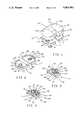
- FIG. 1is a perspective exploded view of a tibial prosthesis according to our invention, showing an upper part with articulating surface and medial and lateral baseplates.
- FIG. 2is a perspective view of the medial and lateral baseplates of FIG. 1.
- FIG. 3is an inverted perspective view of the lateral baseplate of FIG. 2.
- FIG. 4is an inverted perspective view of an alternative embodiment of a baseplate.
- FIG. 5is a perspective view of the upper part with articulating surface of FIG. 1.
- FIG. 6is an inferior perspective view of the upper part of FIG. 5.
- FIG. 7is a front plan view taken of the direction of line 7--7 of FIG. 5.
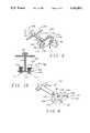
- FIG. 9is a perspective view of an apparatus for implanting the medial and lateral baseplates.
- FIG. 10is a through section of the apparatus of FIG. 9, taken along line 10--10.
- FIG. 8is a perspective view of a guide assembly for use in preparing a resected surface on a tibia.
- a tibial prosthesis 10is shown in exploded perspective view.
- the tibial prosthesis 10comprises a medial baseplate 12 and a separate and independent lateral baseplate 14.
- An upper part with articulating surface 16connects the two baseplates 12, 14.
- a cruciate stem 18attaches the upper part 16 directly to a patient's tibia.
- the lateral baseplate 14comprises an inferior plate 20 with a linear edge 22 adjacent the medial baseplate 12 and an arcuate edge 24 connecting the ends of the interior edge 22.
- a raised lip 26is connected to the arcuate edge 24 and stands proud of the inferior plate 20.
- the cylinder 28has a cavity 32 which opens through the inferior plate 20. In our preferred embodiment, this cavity 32 is cylindrical in form.
- a smaller bore 34is drilled through bottom 36 of the cylinder 28 to attach the lateral baseplate 14 to the tibia.
- a cancellous bone screw(not shown) may be affixed through the bore 34.
- porous areasOn areas of the plate which will be adjacent to bone when the prosthesis 10 is implanted porous areas, such as areas 38, 40, 42 and 44, may be provided to accept bony ingrowth.
- anti-rotation pins 48, 50 on the bottom side 30 of the inferior plate 20may also be used to secure the baseplate 14 to a tibia.
- the cylinder 28is utilized because, as will be more fully explained below, an appropriate cavity can be relatively easily milled into the tibial head.
- An alternative configurationis shown in FIG. 4.
- a frustro-conical or truncated cone eminence 52replaces the cylinder 28.
- a central bore 54may still be provided as well additional lateral bores 56, 58.
- the lateral bores 56, 58may also be used to assist in the placement of the prosthesis 10, as will be explained below.
- porous areas 60, 62are provided to receive bony ingrowth.
- Stabilizing pins 64, 66, 68, 70may be provided to further secure the baseplate to the tibial head.
- the cavity 32has a lip 72 adjacent an upper surface 74 of the inferior plate 20.
- the lip 72engages circular tabs 76, 78 on the upper part 16.
- the lip 72is also used to engage an implantation apparatus 80, shown in FIG. 9. The operation of the implantation apparatus 80 will be more fully explained below.
- two opposed slots 82, 84are milled through the lip 72.
- the medial baseplate 12is substantially the mirror image of the lateral baseplate 14. It has an inferior plate 86 defined by an interior edge 88 adjacent the lateral baseplate 14 and an arcuate edge 90 which connects the ends of the interior edge 88. A lip 92 is attached to the inferior plate 86 along the arcuate edge 90.
- the arcuate edge 24 of the lateral baseplate 14 and the arcuate edge 90 of the medial baseplate 12are of identical size and shape, but of opposite hand. This makes it possible to use a single implantation apparatus 80 for either a left or right knee. We considerate it important, however, to provide a more anatomically accurate articulating surface by making the medial portion of the articulating surface somewhat larger than the lateral surface. This is accomplished by widening the wall 92 at its ends 94, 96.
- the medial baseplateis substantially identical to the lateral baseplate with respect to its lower surface and the cavity, so we will not repeat the description of these parts.
- FIGS. 5-7The upper part with articulating surface 16 is shown in detail in FIGS. 5-7.
- a medial articulating surface 98is separated from a lateral articulating surface 100 by a central prominence 102. Between the two articulating surfaces 98, 100 and posterior to the prominence 102 there is a notch 104 through which ligaments may pass when the prosthesis is implanted in a patient's knee. Anterior from the articulating surfaces 98, 100 there is an elevated ridge 106. A posterior edge of each articulating surface 98, 100 is chamfered 108, 110. As seen in FIGS. 6 and 7, there is a medial baseplate insert 112 and a lateral baseplate 114 configured to mate with the medial baseplate 12 and the lateral baseplate 14 respectively.
- the tabs 76, 78are provided to snap into the baseplates 12, 14.
- the tabs 76, 78each comprise four quarter cylinders 116 with a circumferential lip 118 and chamfered lower exterior edge 120.
- the quarter cylinders 116are grouped together in sets of four to form a circular configuration which can flex radially inward to engage the lips 72 in the cavities.
- a ridge 122having spaced parallel linear edges 124, 126 for engaging the interior edges 88, 22 of the medial baseplate 12 and the lateral baseplate 14 respectively.
- the cruciate stem 18extends from the ridge 122 in a direction generally perpendicular to the baseplate inserts.
- the tibial baseplates 12, 14are preferably manufactured from a rigid biocompatible metal, such as titanium. Each is free to settle on its adjacent bone surface and to form a secure and permanent bond with the bone surface. Even if the shape of the bone surface changes after implantation, due to the different character of the bone across the surface, continuing disease, or unequal loading, the baseplates will not transmit rocking forces from one to the other. Consequently, the baseplates will remain securely implanted on the tibia and bone growth into the porous surfaces may be expected to enhance the long-term stability of the prosthesis.
- a rigid biocompatible metalsuch as titanium
- the upper part 16is preferably composed of high molecular weight polyethylene and is, therefore, slightly plastically deformable in addition, the connection between the baseplates and the inserts should be non-rigid. There should be some play between the tabs and the cavities so that there can be some shifting between the baseplates and the inserts both for the long-term configuration of the prosthesis the surrounding bone adjusts to the presence of the prosthesis and over the short-term as the prosthesis is loaded and unloaded by the patient's movement.
- a surgeonshould first prepare the head of the tibia by resecting a planer surface thereon.
- a surgeonmay choose to use a sagittal saw to freely resect the tibia, or may choose to use the guidance of jigs to establish a more accurate surface. These techniques are known to those skilled in the art and will not be further described here.
- the surgeonshould place a guide assembly 130 on the surface. See FIG. 8.
- the guide assembly 130comprises a handle 132 and an asymmetric template 134.
- the template 134has arcuate lateral portion 136 opposite a relatively larger arcuate medial portion 138.
- the template 134can be inverted so that it can be used for either the right or left knees.
- Four drill bores 140are provided so that the template 134 can be securely located on the resected surface of the tibia. These drill bores, when the bits have been removed, will provide pilot holes for pins such as pins 48 and 50 shown in FIG. 3.
- a milling bit(not shown) with a stop depth ridge is inserted into each of two holes 142 and 144 on the lateral and medial sides of the template to produce cylindrical bores of a desired depth for receiving the cylinders of the baseplates, such as cylinder 28 shown in FIG. 3.
- a cruciate broachis driven through a cruciate opening 146 in the template to form a cavity in the bone for receiving the stem 18.
- the surgeoncan then remove the guide assembly 130 from the tibia.
- the head of the tibiais now prepared to receive a trial prosthesis which is used to ensure that correct sizes have been selected for implantation.
- the components of the trial prosthesisare substantially identical to the actual prosthesis 10 which has been heretofore described.
- the dimensions of the trial prosthesis with respect to the pins, cylinders or the cruciate stem, which would generally affix the prosthesis to the tibia,are slightly smaller than the dimensions of the actual prosthesis 10 so that the trial prosthesis may be removed at an appropriate time.
- the trial prosthesisis implanted in substantially the same manner as the actual prosthesis 10. This process, therefore, will be described hereafter in connection with the actual prosthesis. Once the trial prosthesis has been implanted, the surgeon will ordinarily test the motion of the limb to ensure proper sizing and positioning has been achieved. Then the trial prosthesis would be removed and the actual prosthesis installed.
- This apparatuscomprises a symmetrical baseplate 148 which has two parallel edges 150, 152 connected by a semi-circular edges 154, 156.
- a shaft 158is attached to the center of the plate 148 and perpendicular to the plane thereof.
- a handle 160may be provided for extracting either the trial or actual baseplates as will be explained hereafter.
- a hammer plate 162is attached to one end of the shaft 158.
- Two quick-release latches 164, 166are provided for engaging the medial baseplate 12 and the tibial baseplate 14. Each of these latches 164, 166 is similar and can best be described with reference to FIG.
- Each latchcomprises a circular chamber 168 containing a central shaft 170 with a T-bar 172 at a distal end thereof.
- the shaft 170passes through the plate 148 and can both slide axially and be rotated about its longitudinal axis.
- a knob 171is provided at a proximal end of the shaft.
- Inside the cylinder 168there is a spring 174 which holds the T-bar in a retracted position against the plate 148.
- the T-bars 172are oriented so that they will align with the notches 82, 84 in the baseplate.
- the baseplateis then placed against the plate 148 so that the arcuate edge, for example arcuate edge 24, engages a semi-circular edge, for example edge 156, of the plate.
- the knob 171can then be pushed and turned 90° so that the T-bar 172 engages the lip 72 in the baseplate.
- the spring 174then holds the baseplate against the apparatus 80. With both baseplates attached to the apparatus 80, they can be simultaneously and accurately positioned on the resected surface of the tibia.
- the pins 48 and 50could be aligned with the pilot holes made through the bores 140 of the guide 130.
- the surgeoncan then hammer the prosthesis into place by pounding on the hammer plate 162.
- the trial prosthesiscan be extracted by pulling on the handle 160.
- the actual prosthesis 10can also be extracted in a similar fashion.
- Additional fixation meansmay also be employed as, for example, bone cement, or a cancellous bone screw through the bore 34 of the embodiment of FIG. 3 or through the bores 54, 56 and 58 of the embodiment of FIG. 4.
- the articulating surface insert 16can be pressed into position by driving the cruciate stem 18 into the cavity prepared for it and by snapping the tabs 76, 78 into their respective cavities in the medial and lateral baseplates.
Landscapes
- Health & Medical Sciences (AREA)
- Orthopedic Medicine & Surgery (AREA)
- Transplantation (AREA)
- Heart & Thoracic Surgery (AREA)
- Oral & Maxillofacial Surgery (AREA)
- Cardiology (AREA)
- Engineering & Computer Science (AREA)
- Biomedical Technology (AREA)
- Physical Education & Sports Medicine (AREA)
- Vascular Medicine (AREA)
- Life Sciences & Earth Sciences (AREA)
- Animal Behavior & Ethology (AREA)
- General Health & Medical Sciences (AREA)
- Public Health (AREA)
- Veterinary Medicine (AREA)
- Prostheses (AREA)
Abstract
Description
Claims (49)
Priority Applications (1)
| Application Number | Priority Date | Filing Date | Title |
|---|---|---|---|
| US07/477,745US5062852A (en) | 1990-02-09 | 1990-02-09 | Tibial prosthesis with independent medial and lateral baseplates |
Applications Claiming Priority (1)
| Application Number | Priority Date | Filing Date | Title |
|---|---|---|---|
| US07/477,745US5062852A (en) | 1990-02-09 | 1990-02-09 | Tibial prosthesis with independent medial and lateral baseplates |
Publications (1)
| Publication Number | Publication Date |
|---|---|
| US5062852Atrue US5062852A (en) | 1991-11-05 |
Family
ID=23897186
Family Applications (1)
| Application Number | Title | Priority Date | Filing Date |
|---|---|---|---|
| US07/477,745Expired - LifetimeUS5062852A (en) | 1990-02-09 | 1990-02-09 | Tibial prosthesis with independent medial and lateral baseplates |
Country Status (1)
| Country | Link |
|---|---|
| US (1) | US5062852A (en) |
Cited By (53)
| Publication number | Priority date | Publication date | Assignee | Title |
|---|---|---|---|---|
| US5370699A (en)* | 1993-01-21 | 1994-12-06 | Orthomet, Inc. | Modular knee joint prosthesis |
| US5480445A (en)* | 1994-06-09 | 1996-01-02 | Intermedics Orthopedics, Inc. | Interlocking tibial prosthesis |
| USD372309S (en) | 1995-07-06 | 1996-07-30 | Zimmer, Inc. | Orthopaedic broach impactor |
| US5609645A (en)* | 1994-10-28 | 1997-03-11 | Intermedics, Inc. | Knee revision prosthesis with shims |
| US5613970A (en)* | 1995-07-06 | 1997-03-25 | Zimmer, Inc. | Orthopaedic instrumentation assembly having an offset bushing |
| US5634927A (en)* | 1995-07-06 | 1997-06-03 | Zimmer, Inc. | Sizing plate and drill guide assembly for orthopaedic knee instrumentation |
| US5658341A (en)* | 1993-03-10 | 1997-08-19 | Medinov S.A. | Tibial implant for a knee prosthesis |
| US5755800A (en)* | 1996-12-23 | 1998-05-26 | Johnson & Johnson Professional, Inc. | Modular joint prosthesis augmentation system |
| WO1999037251A1 (en)* | 1998-01-23 | 1999-07-29 | Mathys Medizinaltechnik Ag | Component for an endo-joint prosthesis |
| US6102955A (en)* | 1995-01-19 | 2000-08-15 | Mendes; David | Surgical method, surgical tool and artificial implants for repairing knee joints |
| US6210445B1 (en)* | 1999-10-26 | 2001-04-03 | Bristol-Myers Squibb Company | Tibial knee component with a mobile bearing |
| US6306172B1 (en) | 1999-01-28 | 2001-10-23 | Johnson & Johnson Professional, Inc. | Modular tibial insert for prosthesis system |
| US6387131B1 (en)* | 1997-10-21 | 2002-05-14 | Aesculap | Knee prosthesis comprising a tibial wedge |
| US20030139817A1 (en)* | 2002-01-18 | 2003-07-24 | Finsbury (Development) Limited | Prosthesis |
| US6709461B2 (en) | 1999-02-03 | 2004-03-23 | Depuy Products, Inc. | Modular joint prosthesis system |
| US20040215345A1 (en)* | 2003-02-04 | 2004-10-28 | Zimmer Technology, Inc. | Rotating/non-rotating tibia base plate/insert system |
| US20050119747A1 (en)* | 2002-02-26 | 2005-06-02 | Sdgi Holdings, Inc. | Connectable interbody implant |
| US6923832B1 (en) | 2002-03-21 | 2005-08-02 | Trigon Incorporated | Revision tibial component |
| US20060259149A1 (en)* | 2005-03-07 | 2006-11-16 | David Barrett | Surgical assembly |
| US20070142917A1 (en)* | 2005-10-26 | 2007-06-21 | Roche Christopher P | Apparatus and method to obtain bone fixation |
| WO2007131466A1 (en)* | 2006-05-17 | 2007-11-22 | Kmg Kliniken Ag | Knee endoprosthesis |
| US7326252B2 (en) | 2002-12-20 | 2008-02-05 | Smith & Nephew, Inc. | High performance knee prostheses |
| US20080051908A1 (en)* | 2006-08-22 | 2008-02-28 | Laurent Angibaud | System and method for adjusting the thickness of a prosthesis |
| US20100305575A1 (en)* | 2009-05-29 | 2010-12-02 | Zachary Christopher Wilkinson | Methods and Apparatus for Performing Knee Arthroplasty |
| WO2011004140A2 (en) | 2009-07-04 | 2011-01-13 | Depuy (Ireland) | Surgical instrument |
| US7935151B2 (en) | 2001-03-05 | 2011-05-03 | Hudson Surgical Design, Inc. | Femoral prosthetic implant |
| US7967822B2 (en) | 1994-09-02 | 2011-06-28 | Hudson Surgical Design, Inc. | Methods and apparatus for orthopedic implants |
| US8021368B2 (en) | 2004-01-14 | 2011-09-20 | Hudson Surgical Design, Inc. | Methods and apparatus for improved cutting tools for resection |
| US8114083B2 (en) | 2004-01-14 | 2012-02-14 | Hudson Surgical Design, Inc. | Methods and apparatus for improved drilling and milling tools for resection |
| US8157869B2 (en) | 2007-01-10 | 2012-04-17 | Biomet Manufacturing Corp. | Knee joint prosthesis system and method for implantation |
| US8163028B2 (en) | 2007-01-10 | 2012-04-24 | Biomet Manufacturing Corp. | Knee joint prosthesis system and method for implantation |
| US8187280B2 (en) | 2007-10-10 | 2012-05-29 | Biomet Manufacturing Corp. | Knee joint prosthesis system and method for implantation |
| US8287545B2 (en) | 2004-01-14 | 2012-10-16 | Hudson Surgical Design, Inc. | Methods and apparatus for enhanced retention of prosthetic implants |
| US8328873B2 (en) | 2007-01-10 | 2012-12-11 | Biomet Manufacturing Corp. | Knee joint prosthesis system and method for implantation |
| US8562616B2 (en) | 2007-10-10 | 2013-10-22 | Biomet Manufacturing, Llc | Knee joint prosthesis system and method for implantation |
| US8603095B2 (en) | 1994-09-02 | 2013-12-10 | Puget Bio Ventures LLC | Apparatuses for femoral and tibial resection |
| US8740906B2 (en) | 2004-01-14 | 2014-06-03 | Hudson Surgical Design, Inc. | Method and apparatus for wireplasty bone resection |
| US8926709B2 (en) | 2010-08-12 | 2015-01-06 | Smith & Nephew, Inc. | Structures for use in orthopaedic implant fixation and methods of installation onto a bone |
| US20150057758A1 (en)* | 2013-08-23 | 2015-02-26 | Stryker Corporation | Intraoperative dynamic trialing |
| JP2016127949A (en)* | 2010-01-29 | 2016-07-14 | スミス アンド ネフュー インコーポレーテッド | Cruciate ligament-preserving artificial knee joint |
| WO2016145025A1 (en)* | 2015-03-12 | 2016-09-15 | Zimmer, Inc. | Tibial implant for use in knee arthroplasty |
| US20170100254A1 (en)* | 2015-10-13 | 2017-04-13 | Russell Lloyd | Anterior locking clip |
| US9642711B2 (en) | 2003-10-17 | 2017-05-09 | Smith & Nephew, Inc. | High flexion articular insert |
| US9730712B2 (en) | 2012-10-18 | 2017-08-15 | Smith & Nephew, Inc. | Alignment devices and methods |
| US9730799B2 (en) | 2006-06-30 | 2017-08-15 | Smith & Nephew, Inc. | Anatomical motion hinged prosthesis |
| WO2017218107A1 (en)* | 2016-06-17 | 2017-12-21 | Arthrex, Inc | Components for artificial joints |
| US10092421B2 (en) | 2012-09-28 | 2018-10-09 | Depuy Ireland Unlimited Company | Surgical instrument and method of use |
| US10130480B2 (en) | 2013-03-13 | 2018-11-20 | Howmedica Osteonics Corp. | Modular patella trials |
| US10426565B2 (en) | 2015-03-25 | 2019-10-01 | E. Marlowe Goble | Knee instruments and methods |
| US10568650B2 (en) | 2015-03-25 | 2020-02-25 | E. Marlowe Goble | Knee instruments and methods |
| US11234720B2 (en) | 2018-03-07 | 2022-02-01 | E. Marlowe Goble | Knee instruments and methods |
| US12324749B2 (en) | 2022-07-25 | 2025-06-10 | DePuy Synthes Products, Inc. | Impaction handle for implanting a tibial tray of an orthopaedic knee prosthesis and associated method of making the same |
| US12357470B2 (en) | 2022-12-16 | 2025-07-15 | Depuy Ireland Unlimited Company | Impaction instrument for implanting an orthopaedic knee prosthesis and associated method of using the same |
Citations (3)
| Publication number | Priority date | Publication date | Assignee | Title |
|---|---|---|---|---|
| FR2632516A1 (en)* | 1988-06-10 | 1989-12-15 | Guy Esteve | Single-compartment knee prosthesis comprising a tibial plate with metal seat |
| GB2219942A (en)* | 1988-06-22 | 1989-12-28 | John Polyzoides | Knee prosthesis |
| US4944757A (en)* | 1988-11-07 | 1990-07-31 | Martinez David M | Modulator knee prosthesis system |
- 1990
- 1990-02-09USUS07/477,745patent/US5062852A/ennot_activeExpired - Lifetime
Patent Citations (3)
| Publication number | Priority date | Publication date | Assignee | Title |
|---|---|---|---|---|
| FR2632516A1 (en)* | 1988-06-10 | 1989-12-15 | Guy Esteve | Single-compartment knee prosthesis comprising a tibial plate with metal seat |
| GB2219942A (en)* | 1988-06-22 | 1989-12-28 | John Polyzoides | Knee prosthesis |
| US4944757A (en)* | 1988-11-07 | 1990-07-31 | Martinez David M | Modulator knee prosthesis system |
Cited By (136)
| Publication number | Priority date | Publication date | Assignee | Title |
|---|---|---|---|---|
| US5370699A (en)* | 1993-01-21 | 1994-12-06 | Orthomet, Inc. | Modular knee joint prosthesis |
| US5658341A (en)* | 1993-03-10 | 1997-08-19 | Medinov S.A. | Tibial implant for a knee prosthesis |
| US5480445A (en)* | 1994-06-09 | 1996-01-02 | Intermedics Orthopedics, Inc. | Interlocking tibial prosthesis |
| US9066804B2 (en) | 1994-09-02 | 2015-06-30 | Puget Bioventures Llc | Method and apparatus for femoral and tibial resection |
| US7967822B2 (en) | 1994-09-02 | 2011-06-28 | Hudson Surgical Design, Inc. | Methods and apparatus for orthopedic implants |
| US8603095B2 (en) | 1994-09-02 | 2013-12-10 | Puget Bio Ventures LLC | Apparatuses for femoral and tibial resection |
| US5609645A (en)* | 1994-10-28 | 1997-03-11 | Intermedics, Inc. | Knee revision prosthesis with shims |
| US6102955A (en)* | 1995-01-19 | 2000-08-15 | Mendes; David | Surgical method, surgical tool and artificial implants for repairing knee joints |
| USD372309S (en) | 1995-07-06 | 1996-07-30 | Zimmer, Inc. | Orthopaedic broach impactor |
| US5613970A (en)* | 1995-07-06 | 1997-03-25 | Zimmer, Inc. | Orthopaedic instrumentation assembly having an offset bushing |
| US5634927A (en)* | 1995-07-06 | 1997-06-03 | Zimmer, Inc. | Sizing plate and drill guide assembly for orthopaedic knee instrumentation |
| US5755800A (en)* | 1996-12-23 | 1998-05-26 | Johnson & Johnson Professional, Inc. | Modular joint prosthesis augmentation system |
| US6387131B1 (en)* | 1997-10-21 | 2002-05-14 | Aesculap | Knee prosthesis comprising a tibial wedge |
| WO1999037251A1 (en)* | 1998-01-23 | 1999-07-29 | Mathys Medizinaltechnik Ag | Component for an endo-joint prosthesis |
| AU727988B2 (en)* | 1998-01-23 | 2001-01-04 | Mathys Ag Bettlach | Component for an endo-joint prosthesis |
| US6306172B1 (en) | 1999-01-28 | 2001-10-23 | Johnson & Johnson Professional, Inc. | Modular tibial insert for prosthesis system |
| US6709461B2 (en) | 1999-02-03 | 2004-03-23 | Depuy Products, Inc. | Modular joint prosthesis system |
| US6210445B1 (en)* | 1999-10-26 | 2001-04-03 | Bristol-Myers Squibb Company | Tibial knee component with a mobile bearing |
| US9192391B2 (en) | 2001-03-05 | 2015-11-24 | Puget Bioventures Llc | Method for minimally invasive total knee arthroplasty |
| US9421022B2 (en) | 2001-03-05 | 2016-08-23 | Puget Bioventures Llc | Method and apparatus for total knee arthroplasty |
| US8430932B2 (en) | 2001-03-05 | 2013-04-30 | Puget Bio Ventures LLC | Femoral prosthetic implant |
| US8088167B2 (en) | 2001-03-05 | 2012-01-03 | Hudson Surgical Design, Inc. | Femoral prosthetic implant |
| US8062377B2 (en) | 2001-03-05 | 2011-11-22 | Hudson Surgical Design, Inc. | Methods and apparatus for knee arthroplasty |
| US7935151B2 (en) | 2001-03-05 | 2011-05-03 | Hudson Surgical Design, Inc. | Femoral prosthetic implant |
| US6869448B2 (en) | 2002-01-18 | 2005-03-22 | Finsbury (Development) Limited | Prosthesis |
| US20030139817A1 (en)* | 2002-01-18 | 2003-07-24 | Finsbury (Development) Limited | Prosthesis |
| US20050119747A1 (en)* | 2002-02-26 | 2005-06-02 | Sdgi Holdings, Inc. | Connectable interbody implant |
| US20110282457A1 (en)* | 2002-02-26 | 2011-11-17 | Daniele A Fabris Monterumici | Connectable interbody implant |
| US8002833B2 (en)* | 2002-02-26 | 2011-08-23 | Warsaw Orthopedic, Inc. | Connectable interbody implant |
| US6923832B1 (en) | 2002-03-21 | 2005-08-02 | Trigon Incorporated | Revision tibial component |
| US8652210B2 (en) | 2002-12-20 | 2014-02-18 | Smith & Nephew, Inc. | Femoral prostheses with lateral buttress for patella |
| US9402729B2 (en) | 2002-12-20 | 2016-08-02 | Smith & Nephew, Inc. | High performance knee prostheses |
| US11369477B2 (en) | 2002-12-20 | 2022-06-28 | Smith & Nephew, Inc. | High performance knee prostheses |
| US10149768B2 (en) | 2002-12-20 | 2018-12-11 | Smith & Nephew, Inc. | High performance knee prostheses |
| US9707087B2 (en) | 2002-12-20 | 2017-07-18 | Smith & Nephew, Inc. | High performance knee prosthesis |
| US7922771B2 (en) | 2002-12-20 | 2011-04-12 | Smith & Nephew, Inc. | High performance knee prostheses |
| US9320605B2 (en) | 2002-12-20 | 2016-04-26 | Smith & Nephew, Inc. | High performance knee prostheses |
| US8647389B2 (en) | 2002-12-20 | 2014-02-11 | Smith & Nephew, Inc. | High performance knee prostheses |
| US8603178B2 (en) | 2002-12-20 | 2013-12-10 | Smith & Nephew, Inc. | Knee prostheses with convex portion on tibial lateral articular surface |
| US7326252B2 (en) | 2002-12-20 | 2008-02-05 | Smith & Nephew, Inc. | High performance knee prostheses |
| US8449618B2 (en) | 2002-12-20 | 2013-05-28 | Smith & Nephew, Inc. | High performance knee prostheses |
| US8425617B2 (en) | 2002-12-20 | 2013-04-23 | Smith & Nephew, Inc. | Knee prostheses with convex slope on portion of tibial articular surface |
| US8403992B2 (en) | 2002-12-20 | 2013-03-26 | Smith & Nephew, Inc. | High performance knee prostheses |
| US8398716B2 (en) | 2002-12-20 | 2013-03-19 | Smith & Nephew, Inc. | High performance knee prostheses with posterior cam |
| US8398715B2 (en) | 2002-12-20 | 2013-03-19 | Smith & Nephew, Inc. | High performance knee prostheses with converging anterior and posterior portions |
| US8394147B2 (en) | 2002-12-20 | 2013-03-12 | Smith & Nephew, Inc. | High performance femoral knee prostheses |
| US8394148B2 (en) | 2002-12-20 | 2013-03-12 | Smith & Nephew, Inc. | Tibial component of high performance knee prosthesis |
| US20040215345A1 (en)* | 2003-02-04 | 2004-10-28 | Zimmer Technology, Inc. | Rotating/non-rotating tibia base plate/insert system |
| US8105386B2 (en)* | 2003-02-04 | 2012-01-31 | Zimmer, Inc. | Rotating/non-rotating tibia base plate/insert system |
| US9642711B2 (en) | 2003-10-17 | 2017-05-09 | Smith & Nephew, Inc. | High flexion articular insert |
| US8740906B2 (en) | 2004-01-14 | 2014-06-03 | Hudson Surgical Design, Inc. | Method and apparatus for wireplasty bone resection |
| US8021368B2 (en) | 2004-01-14 | 2011-09-20 | Hudson Surgical Design, Inc. | Methods and apparatus for improved cutting tools for resection |
| US8287545B2 (en) | 2004-01-14 | 2012-10-16 | Hudson Surgical Design, Inc. | Methods and apparatus for enhanced retention of prosthetic implants |
| US8114083B2 (en) | 2004-01-14 | 2012-02-14 | Hudson Surgical Design, Inc. | Methods and apparatus for improved drilling and milling tools for resection |
| US8298238B2 (en) | 2004-01-14 | 2012-10-30 | Hudson Surgical Design, Inc. | Methods and apparatus for pivotable guide surfaces for arthroplasty |
| US9814539B2 (en) | 2004-01-14 | 2017-11-14 | Puget Bioventures Llc | Methods and apparatus for conformable prosthetic implants |
| US8353914B2 (en) | 2004-02-02 | 2013-01-15 | Hudson Surgical Design, Inc. | Methods and apparatus for improved profile based resection |
| US20060259149A1 (en)* | 2005-03-07 | 2006-11-16 | David Barrett | Surgical assembly |
| US8034058B2 (en)* | 2005-03-17 | 2011-10-11 | Depuy International Limited | Tibial cement skirt assembly |
| US20070142917A1 (en)* | 2005-10-26 | 2007-06-21 | Roche Christopher P | Apparatus and method to obtain bone fixation |
| AU2007250380B2 (en)* | 2006-05-17 | 2012-04-05 | Christine Seyfert | Knee endoprosthesis |
| WO2007131466A1 (en)* | 2006-05-17 | 2007-11-22 | Kmg Kliniken Ag | Knee endoprosthesis |
| US10779949B2 (en) | 2006-06-30 | 2020-09-22 | Smith & Nephew, Inc. | Anatomical motion hinged prosthesis |
| US9730799B2 (en) | 2006-06-30 | 2017-08-15 | Smith & Nephew, Inc. | Anatomical motion hinged prosthesis |
| US12383405B2 (en) | 2006-06-30 | 2025-08-12 | Smith & Nephew, Inc. | Anatomical motion hinged prosthesis |
| US20080051908A1 (en)* | 2006-08-22 | 2008-02-28 | Laurent Angibaud | System and method for adjusting the thickness of a prosthesis |
| CN101522136B (en)* | 2006-08-22 | 2012-02-01 | 精密技术公司 | Systems and methods for adjusting the thickness of a prosthesis |
| US8157869B2 (en) | 2007-01-10 | 2012-04-17 | Biomet Manufacturing Corp. | Knee joint prosthesis system and method for implantation |
| US8480751B2 (en) | 2007-01-10 | 2013-07-09 | Biomet Manufacturing, Llc | Knee joint prosthesis system and method for implantation |
| US8163028B2 (en) | 2007-01-10 | 2012-04-24 | Biomet Manufacturing Corp. | Knee joint prosthesis system and method for implantation |
| US8328873B2 (en) | 2007-01-10 | 2012-12-11 | Biomet Manufacturing Corp. | Knee joint prosthesis system and method for implantation |
| US8936648B2 (en) | 2007-01-10 | 2015-01-20 | Biomet Manufacturing, Llc | Knee joint prosthesis system and method for implantation |
| US9763793B2 (en) | 2007-10-10 | 2017-09-19 | Biomet Manufacturing, Llc | Knee joint prosthesis system and method for implantation |
| US8562616B2 (en) | 2007-10-10 | 2013-10-22 | Biomet Manufacturing, Llc | Knee joint prosthesis system and method for implantation |
| US10736747B2 (en) | 2007-10-10 | 2020-08-11 | Biomet Manufacturing, Llc | Knee joint prosthesis system and method for implantation |
| US8187280B2 (en) | 2007-10-10 | 2012-05-29 | Biomet Manufacturing Corp. | Knee joint prosthesis system and method for implantation |
| KR20170087542A (en)* | 2009-05-29 | 2017-07-28 | 스미스 앤드 네퓨, 인크. | Methods and apparatus for performing knee arthroplasty |
| US20100305575A1 (en)* | 2009-05-29 | 2010-12-02 | Zachary Christopher Wilkinson | Methods and Apparatus for Performing Knee Arthroplasty |
| US8998911B2 (en) | 2009-05-29 | 2015-04-07 | Smith & Nephew, Inc. | Methods and apparatus for performing knee arthroplasty |
| CN102665613A (en)* | 2009-05-29 | 2012-09-12 | 史密夫和内修有限公司 | Methods and apparatus for performing knee arthroplasty |
| US20100305711A1 (en)* | 2009-05-29 | 2010-12-02 | Mckinnon Brian W | Methods and Apparatus for Performing Knee Arthroplasty |
| RU2573036C2 (en)* | 2009-05-29 | 2016-01-20 | Смит Энд Нефью, Инк. | Method and device for knee arthroplasty |
| US20100331847A1 (en)* | 2009-05-29 | 2010-12-30 | Zachary Christopher Wilkinson | Methods and Apparatus for Performing Knee Arthroplasty |
| US9943317B2 (en) | 2009-05-29 | 2018-04-17 | Smith & Nephew, Inc. | Methods and apparatus for performing knee arthroplasty |
| US20100331991A1 (en)* | 2009-05-29 | 2010-12-30 | Zachary Christopher Wilkinson | Methods and Apparatus for Performing Knee Arthroplasty |
| US8845645B2 (en) | 2009-05-29 | 2014-09-30 | Smith & Nephew, Inc. | Methods and apparatus for performing knee arthroplasty |
| WO2010138854A3 (en)* | 2009-05-29 | 2011-04-21 | Smith & Nephew, Inc. | Methods and apparatus for performing knee arthroplasty |
| CN102665613B (en)* | 2009-05-29 | 2015-03-25 | 史密夫和内修有限公司 | Apparatus for performing knee arthroplasty |
| US9848888B2 (en) | 2009-05-29 | 2017-12-26 | Smith & Nephew, Inc. | Methods and apparatus for performing knee arthroplasty |
| US8840616B2 (en) | 2009-05-29 | 2014-09-23 | Smith & Nephew, Inc. | Methods and apparatus for performing knee arthroplasty |
| US9668748B2 (en)* | 2009-05-29 | 2017-06-06 | Smith & Nephew, Inc. | Methods and apparatus for performing knee arthroplasty |
| US10743889B2 (en) | 2009-05-29 | 2020-08-18 | Smith & Nephew, Inc. | Methods and apparatus for performing knee arthroplasty |
| US20100331848A1 (en)* | 2009-05-29 | 2010-12-30 | Richard Michael Smith | Methods and Apparatus for Performing Knee Arthroplasty |
| KR20170088443A (en)* | 2009-05-29 | 2017-08-01 | 스미스 앤드 네퓨, 인크. | Methods and apparatus for performing knee arthroplasty |
| US9730705B2 (en) | 2009-05-29 | 2017-08-15 | Smith & Nephew, Inc. | Methods and apparatus for performing knee arthroplasty |
| US8728086B2 (en) | 2009-05-29 | 2014-05-20 | Smith & Nephew, Inc. | Methods and apparatus for performing knee arthroplasty |
| WO2011004140A3 (en)* | 2009-07-04 | 2011-04-28 | Depuy (Ireland) | Surgical instrument |
| AU2010270008B2 (en)* | 2009-07-04 | 2014-09-11 | Depuy Ireland Unlimited Company | Surgical instrument |
| US8597302B2 (en) | 2009-07-04 | 2013-12-03 | Depuy (Ireland) | Surgical instrument |
| WO2011004140A2 (en) | 2009-07-04 | 2011-01-13 | Depuy (Ireland) | Surgical instrument |
| JP2016127949A (en)* | 2010-01-29 | 2016-07-14 | スミス アンド ネフュー インコーポレーテッド | Cruciate ligament-preserving artificial knee joint |
| US8926709B2 (en) | 2010-08-12 | 2015-01-06 | Smith & Nephew, Inc. | Structures for use in orthopaedic implant fixation and methods of installation onto a bone |
| US10898347B2 (en) | 2012-09-28 | 2021-01-26 | Depuy Ireland Unlimited Company | Surgical instrument and method of use |
| US10092421B2 (en) | 2012-09-28 | 2018-10-09 | Depuy Ireland Unlimited Company | Surgical instrument and method of use |
| US11039844B2 (en) | 2012-10-18 | 2021-06-22 | Smith & Nephew, Inc. | Alignment devices and methods |
| US11045213B2 (en) | 2012-10-18 | 2021-06-29 | Smith & Nephew, Inc. | Alignment devices and methods |
| US11076872B2 (en) | 2012-10-18 | 2021-08-03 | Smith & Nephew, Inc. | Alignment devices and methods |
| US10499933B2 (en) | 2012-10-18 | 2019-12-10 | Smith & Nephew, Inc. | Alignment devices and methods |
| US11039843B2 (en) | 2012-10-18 | 2021-06-22 | Smith & Nephew, Inc. | Alignment devices and methods |
| US11033285B2 (en) | 2012-10-18 | 2021-06-15 | Smith & Nephew, Inc. | Alignment devices and methods |
| US10980551B2 (en) | 2012-10-18 | 2021-04-20 | Smith & Nephew, Inc. | Alignment devices and methods |
| US9730712B2 (en) | 2012-10-18 | 2017-08-15 | Smith & Nephew, Inc. | Alignment devices and methods |
| US11707286B2 (en) | 2012-10-18 | 2023-07-25 | Smith & Nephew, Inc. | Alignment devices and methods |
| US11013606B2 (en) | 2013-03-13 | 2021-05-25 | Howmedica Osteonics Corp. | Modular patella trials |
| US11974924B2 (en) | 2013-03-13 | 2024-05-07 | Howmedica Osteonics Corp. | Modular patella trials |
| US10130480B2 (en) | 2013-03-13 | 2018-11-20 | Howmedica Osteonics Corp. | Modular patella trials |
| US11045209B2 (en) | 2013-08-23 | 2021-06-29 | Howmedica Osteonics Corp. | Intraoperative dynamic trialing |
| US11602356B2 (en) | 2013-08-23 | 2023-03-14 | Howmedica Osteonics Corp. | Intraoperative dynamic trialing |
| US10194919B2 (en) | 2013-08-23 | 2019-02-05 | Howmedica Osteonics Corp. | Intraoperative dynamic trialing |
| US20150057758A1 (en)* | 2013-08-23 | 2015-02-26 | Stryker Corporation | Intraoperative dynamic trialing |
| US9427336B2 (en)* | 2013-08-23 | 2016-08-30 | Stryker Corporation | Intraoperative dynamic trialing |
| WO2016145025A1 (en)* | 2015-03-12 | 2016-09-15 | Zimmer, Inc. | Tibial implant for use in knee arthroplasty |
| US10426565B2 (en) | 2015-03-25 | 2019-10-01 | E. Marlowe Goble | Knee instruments and methods |
| US11337711B2 (en) | 2015-03-25 | 2022-05-24 | E. Marlowe Goble | Knee instruments and methods |
| US11246609B2 (en) | 2015-03-25 | 2022-02-15 | E. Marlowe Goble | Knee instruments and methods |
| US11266423B2 (en) | 2015-03-25 | 2022-03-08 | E. Marlowe Goble | Knee instruments and methods |
| US10568650B2 (en) | 2015-03-25 | 2020-02-25 | E. Marlowe Goble | Knee instruments and methods |
| US11304814B2 (en) | 2015-10-13 | 2022-04-19 | Biomet Uk Healthcare Limited | Anterior locking clip |
| US20170100254A1 (en)* | 2015-10-13 | 2017-04-13 | Russell Lloyd | Anterior locking clip |
| US10517735B2 (en)* | 2015-10-13 | 2019-12-31 | Biomet Uk Healthcare Limited | Anterior locking clip |
| US11633283B2 (en) | 2016-06-17 | 2023-04-25 | Arthrex, Inc. | Components for artificial joints |
| WO2017218107A1 (en)* | 2016-06-17 | 2017-12-21 | Arthrex, Inc | Components for artificial joints |
| US10512543B2 (en) | 2016-06-17 | 2019-12-24 | Arthrex, Inc. | Components for artificial joints |
| US11234720B2 (en) | 2018-03-07 | 2022-02-01 | E. Marlowe Goble | Knee instruments and methods |
| US12324749B2 (en) | 2022-07-25 | 2025-06-10 | DePuy Synthes Products, Inc. | Impaction handle for implanting a tibial tray of an orthopaedic knee prosthesis and associated method of making the same |
| US12357470B2 (en) | 2022-12-16 | 2025-07-15 | Depuy Ireland Unlimited Company | Impaction instrument for implanting an orthopaedic knee prosthesis and associated method of using the same |
Similar Documents
| Publication | Publication Date | Title |
|---|---|---|
| US5062852A (en) | Tibial prosthesis with independent medial and lateral baseplates | |
| AU727550B2 (en) | Modular instrumentation for bone preparation and implant trial reduction of orthopedic implants | |
| US5246459A (en) | Modular tibial support pegs for the tibial component of a prosthetic knee replacement system | |
| EP0797417B1 (en) | Knee prosthesis with shims | |
| US7766969B2 (en) | Modular progressive implant for a joint articulation surface | |
| US6139581A (en) | Posterior compensation tibial tray | |
| US4578081A (en) | Bone prosthesis | |
| EP1480582B1 (en) | Patello-femoral joint replacement | |
| EP0510103B1 (en) | Prosthesis | |
| CA2431401C (en) | Massive modular system | |
| US5879354A (en) | Prosthetic implant | |
| US7963969B2 (en) | Provisional orthopedic implant and recutting instrument guide | |
| CA2628841A1 (en) | Mounting system and method for enhancing implant fixation to bone | |
| AU2008255226A1 (en) | Knee arthroplasty prosthesis and method | |
| JPH0548699B2 (en) | ||
| EP2712589B1 (en) | Surgical instrument | |
| AU2014201412B2 (en) | Surgical instrument and method of use | |
| US20230157831A1 (en) | Tibial component of endoprosthetic knee implant, kits and instruments therefore, and methods of use | |
| US11826257B2 (en) | Tibial preparation | |
| GB2534140A (en) | Joint prosthesis supporting assembly | |
| CA1330688C (en) | Modular joint prosthesis |
Legal Events
| Date | Code | Title | Description |
|---|---|---|---|
| AS | Assignment | Owner name:INTERMEDICS ORTHOPEDICS, INC., A CORP. OF TX. Free format text:ASSIGNMENT OF ASSIGNORS INTEREST.;ASSIGNORS:DORR, LAWRENCE D.;BURKINSHAW, BRIAN D.;SKRABA, JOSEPH S.;REEL/FRAME:005229/0825;SIGNING DATES FROM 19900207 TO 19900209 | |
| STCF | Information on status: patent grant | Free format text:PATENTED CASE | |
| FEPP | Fee payment procedure | Free format text:PAYOR NUMBER ASSIGNED (ORIGINAL EVENT CODE: ASPN); ENTITY STATUS OF PATENT OWNER: LARGE ENTITY | |
| FPAY | Fee payment | Year of fee payment:4 | |
| FPAY | Fee payment | Year of fee payment:8 | |
| AS | Assignment | Owner name:CENTERPULSE ORTHOPEDICS INC., TEXAS Free format text:CHANGE OF NAME;ASSIGNOR:SULZER ORTHOPEDICS INC.;REEL/FRAME:013516/0549 Effective date:20020930 | |
| FPAY | Fee payment | Year of fee payment:12 | |
| AS | Assignment | Owner name:SULZER ORTHOPEDICS, INC., ILLINOIS Free format text:CHANGE OF NAME;ASSIGNOR:INTERMEDICS ORTHOPEDICS, INC.;REEL/FRAME:015177/0137 Effective date:19970106 | |
| AS | Assignment | Owner name:CENTERPULSE ORTHOPEDICS INC., TEXAS Free format text:CHANGE OF NAME;ASSIGNOR:SULZER ORTHOPEDICS INC.;REEL/FRAME:016761/0136 Effective date:20020930 | |
| AS | Assignment | Owner name:ZIMMER, INC., INDIANA Free format text:ASSIGNMENT OF ASSIGNORS INTEREST;ASSIGNOR:DORR, LAWRENCE D.;REEL/FRAME:022973/0364 Effective date:20090711 |