US5062648A - Seal for rotating torque tube with seal valve - Google Patents
Seal for rotating torque tube with seal valveDownload PDFInfo
- Publication number
- US5062648A US5062648AUS07/496,883US49688390AUS5062648AUS 5062648 AUS5062648 AUS 5062648AUS 49688390 AUS49688390 AUS 49688390AUS 5062648 AUS5062648 AUS 5062648A
- Authority
- US
- United States
- Prior art keywords
- drive shaft
- fluid
- tight seal
- establishing
- preventing leakage
- Prior art date
- Legal status (The legal status is an assumption and is not a legal conclusion. Google has not performed a legal analysis and makes no representation as to the accuracy of the status listed.)
- Expired - Lifetime
Links
Images

Classifications
- A—HUMAN NECESSITIES
- A61—MEDICAL OR VETERINARY SCIENCE; HYGIENE
- A61B—DIAGNOSIS; SURGERY; IDENTIFICATION
- A61B17/00—Surgical instruments, devices or methods
- A61B17/32—Surgical cutting instruments
- A61B17/3205—Excision instruments
- A61B17/3207—Atherectomy devices working by cutting or abrading; Similar devices specially adapted for non-vascular obstructions
- A61B17/320758—Atherectomy devices working by cutting or abrading; Similar devices specially adapted for non-vascular obstructions with a rotating cutting instrument, e.g. motor driven
- A—HUMAN NECESSITIES
- A61—MEDICAL OR VETERINARY SCIENCE; HYGIENE
- A61M—DEVICES FOR INTRODUCING MEDIA INTO, OR ONTO, THE BODY; DEVICES FOR TRANSDUCING BODY MEDIA OR FOR TAKING MEDIA FROM THE BODY; DEVICES FOR PRODUCING OR ENDING SLEEP OR STUPOR
- A61M39/00—Tubes, tube connectors, tube couplings, valves, access sites or the like, specially adapted for medical use
- A61M39/02—Access sites
- A61M39/06—Haemostasis valves, i.e. gaskets sealing around a needle, catheter or the like, closing on removal thereof
- A61M39/0613—Haemostasis valves, i.e. gaskets sealing around a needle, catheter or the like, closing on removal thereof with means for adjusting the seal opening or pressure
- F—MECHANICAL ENGINEERING; LIGHTING; HEATING; WEAPONS; BLASTING
- F16—ENGINEERING ELEMENTS AND UNITS; GENERAL MEASURES FOR PRODUCING AND MAINTAINING EFFECTIVE FUNCTIONING OF MACHINES OR INSTALLATIONS; THERMAL INSULATION IN GENERAL
- F16J—PISTONS; CYLINDERS; SEALINGS
- F16J15/00—Sealings
- F16J15/16—Sealings between relatively-moving surfaces
- F16J15/32—Sealings between relatively-moving surfaces with elastic sealings, e.g. O-rings
- F16J15/3204—Sealings between relatively-moving surfaces with elastic sealings, e.g. O-rings with at least one lip
- Y—GENERAL TAGGING OF NEW TECHNOLOGICAL DEVELOPMENTS; GENERAL TAGGING OF CROSS-SECTIONAL TECHNOLOGIES SPANNING OVER SEVERAL SECTIONS OF THE IPC; TECHNICAL SUBJECTS COVERED BY FORMER USPC CROSS-REFERENCE ART COLLECTIONS [XRACs] AND DIGESTS
- Y10—TECHNICAL SUBJECTS COVERED BY FORMER USPC
- Y10T—TECHNICAL SUBJECTS COVERED BY FORMER US CLASSIFICATION
- Y10T137/00—Fluid handling
- Y10T137/7722—Line condition change responsive valves
- Y10T137/7837—Direct response valves [i.e., check valve type]
- Y10T137/7879—Resilient material valve
- Y10T137/788—Having expansible port
- Y10T137/7882—Having exit lip
Definitions
- the present inventionpertains to devices and apparatus which can be used to establish fluid-tight seals between separate structural elements. More particularly, the present invention pertains to devices and apparatus which are useable to establish fluid-tight seals between structural elements that move relative to each other, and to maintain the fluid-tight seals when the structural elements are adjusted or disconnected.
- the present inventionis particularly, but not exclusively, useful for establishing a fluid-tight seal around a rotatable drive shaft, and for maintaining such a fluid-tight seal during insertion or removal of the shaft from an associated rotating drive assembly.
- fluid-tight sealsare required for medical devices whenever there is a need to either prevent the loss of fluid or prevent fluid from becoming tainted by contact or interaction with a contaminant.
- problems which must be overcome to establish a fluid-tight sealare particularly troublesome when the seal is required between elements that move relative to each other.
- Atherectomy devicesare used in vascular surgery to open stenotic segments in arteries by removing plaque from the arterial wall.
- atherectomy deviceshave some unique requirements which result from their mechanical requirements.
- atherectomy deviceshave rotating parts which must be able to function simultaneously both inside and outside the body without causing an excessive loss of blood.
- 213,691 for an invention entitled "Cutter for Atherectomy Device” and which is assigned to the same assignee as the present inventionrequires the rotation of a cutter element inside an artery by an external drive unit to excise the plaque from the artery. Since both the rotating cutter and the rotating drive shaft must be positioned within the artery and operated by apparatus external to the body, there is a need to provide some means whereby their simultaneous operation can be controlled without an excessive loss of blood. Further, it happens that various sized drive shafts, having different diameters, may need to be used. Additionally, it may be necessary to change drive shafts or cutters and it may also be necessary to rotate the drive shafts at high rotational speeds for extended periods of time.
- the drive shaft and cutterare typically placed inside a catheter sheath which establishes access to the artery and which can extend into the artery to effectively isolate the rotating elements of the atherectomy device from direct contact with any tissue other than the plaque which is to be removed.
- bloodenters the sheath and, consequently, fluid-tight seals are necessaryy to prevent the loss of blood through the gaps between the sheath and the rotating drive shaft.
- Fluid-tight sealsmust also be maintained while changing drive shafts. As will be appreciated, this can involve moving various drive shafts into and out of the sheath. Accordingly, the specific interest of the present invention is maintaining fluid-tight seals which are necessary for the proper operation of an atherectomy device.
- a device for establishing a fluid-tight seal around a rotatable drive shaftcomprises an annular seal member, a housing for holding the seal member around the shaft, and an actuator which urges the seal member against the housing to establish the fluid-tight seal by constricting the seal member against the shaft.
- the devicealso includes a seal valve mounted in the housing which automatically closes to prevent loss of fluid when the shaft is removed from the housing.
- the housingis a rigid member that is formed with a longitudinal bore through which the drive shaft is positioned. Further, this bore is formed with a narrow tubular portion, a wide tubular portion which is axially aligned with the narrow portion, and a tapered portion which provides a transition between the wide and the narrow portions.
- the seal member of the present inventionis an annular tube which is beveled to form an aperture at one end, and which has a radial ring extending peripherally from its outer surface. Additionally, the seal member has a radial groove formed into its inner surface. In its cooperation with the housing, the seal member is seated in the wide portion of the bore with its beveled end abutting the tapered portion of the bore to align the aperture of the seal member with the narrow portion of the bore. As so seated, the ring on the outer surface of the seal member is in a fluid-tight engagement with the surface of the wide portion.
- the actuatoris a tubular-shaped member which is formed with a longitudinal passageway that is axially aligned with the bore of the housing when the actuator and housing are engaged.
- the actuatorhas threads which are threadably engageable with the housing.
- ithas a detent ring which is snappingly engageable with the groove of the seal member to hold the seal member against the actuator.
- the narrow portion of the housinghas an expanded conforming portion that includes an annular groove into which a seal valve is seated.
- the seal valvehas a hollow cylindrical base which includes an outer annular ring portion that is shaped to fit into the annular groove of the expanded conforming portion. Integral with the base of the seal valve is a hollow wedge-shaped portion formed by a pair of flexible flaps. The flexible flaps taper from the cylindrical base to form a long narrow aperture or slit, and are resiliently biased together so the slit is normally closed.
- the flapsare sufficiently flexible to allow a drive shaft to be placed through the slit of the seal valve, yet the flaps are sufficiently firm so that when the shaft is removed from the seal valve, the flaps are biased together to close the slit and form a fluid barrier across the housing. Additionally, flaps of the seal valve can close around the shaft to help prevent flow of fluid through the housing while the shaft is operationally inserted through the housing.
- the seal valveis positioned so that the annular ring portion of the seal valve fits into the annular groove of the housing, with the wedge-shaped portion located in the expanded narrow portion of the housing.
- the seal valvein its cooperation with the housing, the seal valve is seated so that the annular ring engages the radial groove in the interior surface of the housing to establish a fluid-tight engagement between the seal valve and the housing.
- the seal valveis positioned with the hollow wedge-shaped portion positioned pointing in a direction the same as the direction of insertion of the drive shaft.
- the drive shaftwhen the drive shaft is positioned through the passageway of the actuator and on through the bore of the housing, it enters the open end of the cylindrical base of the seal valve and exits through the slit at the opposite end of the wedge-shaped portion.
- Each flap which forms the wedge-shaped portiondeforms to accommodate the drive shaft.
- Each flapis sufficiently flexible and resilient to seal onto the shaft and help prevent leakage around the shaft and to return to its original wedge shape for closing the slit after the drive shaft is withdrawn from the seal valve.
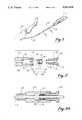
- FIG. 1is a perspective view of the device of the present invention shown in combination with an atherectomy apparatus;
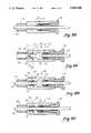
- FIG. 2is an exploded view of the device of the present invention with its components shown in cross section for clarity;
- FIG. 3Ais a cross-sectional view of the device as seen along the line 3--3 in FIG. 1 with the seal member disengaged from the drive shaft;
- FIG. 3Bis a cross-sectional view of the device as seen along the line 3--3 in FIG. 1 with the seal member engaged with the drive shaft;
- FIG. 4Ais a cross-sectional view of an embodiment of the device incorporating a seal valve as seen along the line 3--3 in FIG. 1, with the drive shaft disengaged from the seal valve;
- FIG. 4Bis a cross-sectional view of the device of FIG. 5A as seen along the line 3--3 in FIG. 1 with the drive shaft engaged with the seal valve, but disengaged from the seal member;
- FIG. 4Cis a cross-sectional view of the device as seen along the line 3--3 in FIG. 1 with the drive shaft engaged with both the seal valve and with the seal member;
- FIG. 5Ais a perspective view of the seal valve itself shown disengaged from the drive shaft
- FIG. 5Bis a perspective view of the seal valve itself engaged with the drive shaft
- FIG. 6is a perspective view of an alternative embodiment of the seal valve; and FIG. 7 is a cross-sectional view of the seal valve of FIG. 6 taken along the line 7--7.
- the device for establishing a fluid-tight seal around a rotatable drive shaftis shown and designated 10.
- the device 10is used in an atherectomy system essentially comprising a drive unit 12 which rotates both a drive shaft 14 and a cutter (not shown) that is attached to the drive shaft 14.
- a sheath 18is engaged in a fluid-tight attachment with the device 10 and extends from the device 10 into an artery of patient 16. Sheath 18 thus surroundingly receives the drive shaft 14 and cutter (not shown). In its surrounding position, the sheath 18 isolates the rotating drive shaft 14 from direct contact with body tissue other than that which is to be excised from the stenotic segment of the artery by the rotating action of the cutter.
- housing 20is a cylindrical-shaped component which is formed with a bore 26 that has a narrow portion 28, a wide portion 30 and a tapered portion 32 which is intermediate narrow portion 28 and wide portion 30.
- wide portion 30is formed with threads 34 which provide means for engaging housing 20 with actuator 24 for purposes to be subsequently disclosed.
- housing 20is made of a rigid material such as a plastic or a metal.
- the seal member 22is tubular-shaped and has a beveled end 36 which surrounds and defines an aperture 38. Distanced from the beveled end 36 on seal member 22, is a raised ring 39 which is formed radially on the outer surface 40 of member 22 and which extends peripherally around the member 22. On the inner surface 42 of seal member 22, a groove 44 is formed for a purpose to be subsequently discussed.
- seal member 22is made of a resilient elastomeric material such as rubber.
- the bevel angle 46 defined between the surface 40 of member 22 and the surface of beveled end 36be smaller than the taper angle 48 which defines the transition from narrow portion 28 to tapered portion 32. This is so, as will become more apparent after subsequent disclosure, in order to ensure the constriction of aperture 38 whenever beveled end 36 of seal member 22 is urged against tapered portion 32 in bore 26 of housing 20.
- the actuator 24 of device 10is shown in FIG. 2 as an elongated member which has a passageway 50 formed longitudinally through the actuator 24.
- a knob 52is formed on actuator 24 for rotating the actuator 24 and a threaded shaft 54 is created to provide for a threadable engagement of the actuator 24 with housing 20.
- Actuator 24also has a radial engagement flange 56 which is snappingly engageable with groove 44 of seal member 22 to hold seal member 22 onto actuator 24.
- FIG. 3AThe cooperation of structure for components of device 10 is perhaps best seen in FIG. 3A wherein it is shown that flange 56 of actuator 24 is seated in the groove 44 of seal member 22 to hold seal member 22 onto actuator 24. Further, threaded shaft 54 of actuator 24 is engaged with the threads 34 of housing 20 to connect actuator 24 with housing 20. This arrangement places the seal member 22 in wide portion 30 of bore 26 and aligns the aperture 38 of seal member 22 with the narrow portion 28 of bore 26 and the passageway 50 of actuator 24. This alignment, as seen in FIG. 3A, allows actuator 24, seal member 22 and housing 20 to receive drive shaft 14, and permits the drive shaft 14 to extend completely through the device 10.
- actuator 24is movable together with seal member 22 relative to housing 20. Specifically, in the position shown in FIG. 3A, aperture 38 is released from drive shaft 14 and a fluid-tight seal is not established between the drive shaft 14 and the seal member 22. This configuration permits removal and replacement of drive shaft 14 by the operator as discussed above.
- knob 52is rotated to advance actuator 24 into bore 26 of housing 20, seal member 22 is urged into contact with tapered portion 32 to constrict the aperture 38 onto drive shaft 14 as substantially shown in FIG. 3B.
- actuator 24 and seal member 22are engaged to each other in a desmodromic, or tethered, relationship. Consequently, seal member 22 and actuator 24 are moved in concert.
- the advancement of actuator 24 into bore 26positively engages seal member 22 in a fluid-tight relationship around drive shaft 14.
- the withdrawal of actuator 24 from bore 26positively disengages seal member 22 from its engagement with drive shaft 14.
- the device 10includes a housing 20 which has an expanded conforming portion 60, that is adjacent narrow portion 28. Located between conforming portion 60 and narrow portion 28 is an annular groove 62. Seated in annular groove 62 is a seal valve 64, which is preferably made of a resilient elastomeric material such as rubber. Specifically seal valve 64 has a hollow cylindrical base 66, which includes an outer annular ring portion 68 that fits into annular groove 62. Formed onto cylindrical base 66 is a hollow wedge-shaped portion 70. As can perhaps best be appreciated with reference to FIGS.
- wedge-shaped portion 70 of seal valve 64is formed by a pair of generally flat resiliently flexible flaps 72. Flaps 72 are resiliently biased together and taper from cylindrical base 66 down to a long narrow aperture or slit 74. As shown in FIG. 5A, flaps 72 are biased to be normally closed. Flaps 72 are also flexibly deformable as can be seen in FIG. 5B, to allow a drive shaft 14 to be inserted or placed through slit 74. When shaft 14 is positioned through seal valve 64, flaps 72 envelop shaft 14 to somewhat restrict fluid flow, yet allow movement of shaft 14.
- seal valve 64Cooperation of seal valve 64 incorporated in housing 20 can best be seen in FIGS. 4A, 4B and 4C.
- drive shaft 14has been inserted through actuator 24, and through seal member 22.
- end 76 of drive shaft 14is positioned within wide portion 30 of housing 20.
- seal valve 64if fluid is in wide portion 30, such fluid could possibly leak out of device 10.
- such leakagemight occur around shaft 14 and along inner surface 42 since actuator 24 has not yet been tightened to seat seal member 22 in fluid-tight engagement with shaft 14, as in FIGS. 3B and 4C. Therefore, seal valve 64 is positioned in housing 20, as seen in FIG. 4A to prevent any leaking of fluid from the fluid volume held in sheath 18 into wide portion 30.
- seal valve 64is needed to prevent fluid flow from sheath 18 out through the device 10. Due to the design of wedge-shaped portion 70, when shaft 14 has been removed, any additional back fluid pressure from the fluid in sheath 18 presses on flap 72 to close seal valve 64, and thereby provide an even tighter fluid-tight seal.
- drive shaft 14can be slidably moved on through slit 74 of hollow seal valve 64 into sheath 18. Again, leakage of fluid is minimized due to the resilient action of flaps 72 which envelop shaft 14, as illustrated in FIG. 5B. Also, fluid pressure on the outside of tapered flaps 72 continues to help maintain a relatively tight seal about shaft 14.
- FIGS. 6 and 7there is shown in FIGS. 6 and 7, an alternative embodiment 64' of the seal valve.
- hollow cylindrical base 66is elongated, with outer ring 68 located at an end opposite wedge-shaped portion 70.
- Hollow cylindrical base 66has an outer ring 68 which provides a snug fit with groove 62 of expanded narrow portion 60.
- seal valve 64'also fits into housing 20 as substantially shown in FIGS. 4A, 4B and 4C, and works similarly to seal valve 64 to provide a closable seal about shaft 14 when it is placed through slit 74.
Landscapes
- Health & Medical Sciences (AREA)
- Engineering & Computer Science (AREA)
- Life Sciences & Earth Sciences (AREA)
- Heart & Thoracic Surgery (AREA)
- Public Health (AREA)
- General Engineering & Computer Science (AREA)
- Biomedical Technology (AREA)
- Surgery (AREA)
- Animal Behavior & Ethology (AREA)
- General Health & Medical Sciences (AREA)
- Veterinary Medicine (AREA)
- Pulmonology (AREA)
- Vascular Medicine (AREA)
- Nuclear Medicine, Radiotherapy & Molecular Imaging (AREA)
- Anesthesiology (AREA)
- Medical Informatics (AREA)
- Molecular Biology (AREA)
- Hematology (AREA)
- Mechanical Engineering (AREA)
- Details Of Valves (AREA)
- Sealing Devices (AREA)
Abstract
Description
Claims (26)
Priority Applications (5)
| Application Number | Priority Date | Filing Date | Title |
|---|---|---|---|
| US07/496,883US5062648A (en) | 1989-09-26 | 1990-03-21 | Seal for rotating torque tube with seal valve |
| CA 2016905CA2016905C (en) | 1989-09-26 | 1990-05-16 | Seal for rotating torque tube with seal valve |
| AU56183/90AAU625943B2 (en) | 1990-03-21 | 1990-05-31 | Seal for rotating torque tube with seal valve |
| JP2156602AJPH03282068A (en) | 1990-03-21 | 1990-06-14 | Leakage preventive device at time when fluid sealing seal is mounted around rotatable driving shaft |
| EP19900307894EP0420395A3 (en) | 1989-09-26 | 1990-07-19 | Seal for rotating torque tube with seal valve |
Applications Claiming Priority (2)
| Application Number | Priority Date | Filing Date | Title |
|---|---|---|---|
| US41300389A | 1989-09-26 | 1989-09-26 | |
| US07/496,883US5062648A (en) | 1989-09-26 | 1990-03-21 | Seal for rotating torque tube with seal valve |
Related Parent Applications (1)
| Application Number | Title | Priority Date | Filing Date |
|---|---|---|---|
| US41300389AContinuation-In-Part | 1989-09-26 | 1989-09-26 |
Publications (1)
| Publication Number | Publication Date |
|---|---|
| US5062648Atrue US5062648A (en) | 1991-11-05 |
Family
ID=27022018
Family Applications (1)
| Application Number | Title | Priority Date | Filing Date |
|---|---|---|---|
| US07/496,883Expired - LifetimeUS5062648A (en) | 1989-09-26 | 1990-03-21 | Seal for rotating torque tube with seal valve |
Country Status (3)
| Country | Link |
|---|---|
| US (1) | US5062648A (en) |
| EP (1) | EP0420395A3 (en) |
| CA (1) | CA2016905C (en) |
Cited By (29)
| Publication number | Priority date | Publication date | Assignee | Title |
|---|---|---|---|---|
| DE4243561A1 (en)* | 1992-12-22 | 1994-06-23 | Richter Chemie Technik Gmbh | Gland packing |
| US5387395A (en)* | 1992-07-06 | 1995-02-07 | Beckman Instruments, Inc. | Fluid distribution manifold |
| US5896640A (en)* | 1996-11-12 | 1999-04-27 | Husky Injection Molding Systems Ltd. | Deflection sealing apparatus and method |
| US6022363A (en)* | 1998-12-16 | 2000-02-08 | Micro Therapeutics, Inc. | Rotatable dynamic seal and guide for a medical obstruction treatment device sub-assembly coupled to a drive motor unit |
| US6024729A (en)* | 1998-03-10 | 2000-02-15 | Vernay Laboratories, Inc. | Hemostasis valve assembly including guide wire seal |
| US6050572A (en)* | 1998-03-09 | 2000-04-18 | Bal Seal Engineering Company, Inc. | Rotary cartridge seals with retainer |
| US6066152A (en)* | 1998-12-16 | 2000-05-23 | Micro Therapeutics, Inc. | Rotatable attachment mechanism for attaching a medical obstruction treatment device sub-assembly to a drive motor unit |
| US6090118A (en)* | 1998-07-23 | 2000-07-18 | Mcguckin, Jr.; James F. | Rotational thrombectomy apparatus and method with standing wave |
| US20040230213A1 (en)* | 2000-04-05 | 2004-11-18 | Pathway Medical Technologies, Inc. | Liquid seal assembly for a rotating torque tube |
| US7037316B2 (en) | 1997-07-24 | 2006-05-02 | Mcguckin Jr James F | Rotational thrombectomy device |
| US20090105687A1 (en)* | 2007-10-05 | 2009-04-23 | Angioscore, Inc. | Scoring catheter with drug delivery membrane |
| US7645261B2 (en) | 1999-10-22 | 2010-01-12 | Rex Medical, L.P | Double balloon thrombectomy catheter |
| US7686824B2 (en) | 2003-01-21 | 2010-03-30 | Angioscore, Inc. | Apparatus and methods for treating hardened vascular lesions |
| US20100193516A1 (en)* | 2009-02-02 | 2010-08-05 | Labean Robert J | Dual sealing system for use with a probe |
| US8080026B2 (en) | 2003-01-21 | 2011-12-20 | Angioscore, Inc. | Apparatus and methods for treating hardened vascular lesions |
| US8414543B2 (en) | 1999-10-22 | 2013-04-09 | Rex Medical, L.P. | Rotational thrombectomy wire with blocking device |
| US20140094839A1 (en)* | 2012-09-28 | 2014-04-03 | Ninepoint Medical, Inc. | Mechanical tensioning device |
| US8864743B2 (en) | 2005-05-11 | 2014-10-21 | Angioscore, Inc. | Methods and systems for delivering substances into luminal walls |
| US20150127093A1 (en)* | 2013-09-10 | 2015-05-07 | Edwards Lifesciences Corporation | Magnetic retaining mechanisms for prosthetic valves |
| US9173977B2 (en) | 2010-04-19 | 2015-11-03 | Angioscore, Inc. | Coating formulations for scoring or cutting balloon catheters |
| US9351756B2 (en) | 2010-09-21 | 2016-05-31 | Angioscore, Inc. | Method and system for treating valve stenosis |
| US9375328B2 (en) | 2001-11-09 | 2016-06-28 | Angioscore, Inc. | Balloon catheter with non-deployable stent |
| US10086178B2 (en) | 2001-11-09 | 2018-10-02 | Angioscore, Inc. | Balloon catheter with non-deployable stent |
| US10117668B2 (en) | 2013-10-08 | 2018-11-06 | The Spectranetics Corporation | Balloon catheter with non-deployable stent having improved stability |
| US20190001081A1 (en)* | 2015-12-21 | 2019-01-03 | 3M Innovative Properties Company | Flow governors for use in medicinal inhalers |
| US20190224450A1 (en)* | 2018-01-19 | 2019-07-25 | St. Jude Medical, Cardiology Division, Inc. | Locking guide catheter hubs |
| US20210000498A1 (en)* | 2018-03-29 | 2021-01-07 | Terumo Kabushiki Kaisha | Medical device having rotating shaft with lumen and sealing structure |
| CN112312957A (en)* | 2018-06-21 | 2021-02-02 | 费森尤斯卡比德国有限公司 | Connector for connecting a first medical line to a second medical line |
| US11407560B2 (en)* | 2017-04-12 | 2022-08-09 | Jeffrey Mason Clifford | Liquid container having integrated auxiliary flask |
Families Citing this family (5)
| Publication number | Priority date | Publication date | Assignee | Title |
|---|---|---|---|---|
| US5338314A (en)* | 1991-04-22 | 1994-08-16 | B. Braun Medical, Inc. | Rotating Y-connector |
| US5423846A (en)* | 1991-10-21 | 1995-06-13 | Cathco, Inc. | Dottering auger catheter system |
| US5836306A (en)* | 1994-12-23 | 1998-11-17 | Bard Connaught | Exchange accessory for use with a monorail catheter |
| EP2378988B1 (en) | 2009-01-09 | 2016-04-20 | Applied Medical Resources Corporation | Pleated trocar shield |
| US10646235B2 (en)* | 2017-10-26 | 2020-05-12 | DePuy Synthes Products, Inc. | Guide wire seal for reamer irrigator aspirator system |
Citations (41)
| Publication number | Priority date | Publication date | Assignee | Title |
|---|---|---|---|---|
| US52742A (en)* | 1866-02-20 | Improvement in piston-rod packing | ||
| GB107100A (en)* | 1900-01-01 | |||
| US657007A (en)* | 1899-10-28 | 1900-08-28 | Franz Richter | Valve for pneumatic tires of bicycles. |
| US831139A (en)* | 1903-07-22 | 1906-09-18 | Wm T Bonner Co | Gage-fitting. |
| US1603556A (en)* | 1924-05-19 | 1926-10-19 | Frank L Platt | Packing gland |
| US2204915A (en)* | 1938-11-04 | 1940-06-18 | Mission Mfg Co | Stuffing gland |
| US2270054A (en)* | 1939-10-13 | 1942-01-13 | Georgia Iron Works | Water seal for pumps |
| US2328382A (en)* | 1941-10-08 | 1943-08-31 | Jesse D Langdon | Flexible check valve and vacuum breaker |
| US2605784A (en)* | 1948-12-17 | 1952-08-05 | Kenneth M Snider | Check valve |
| US2688329A (en)* | 1953-03-19 | 1954-09-07 | American Cystoscope Makers Inc | Catheter |
| US2721749A (en)* | 1952-08-29 | 1955-10-25 | Howard M Crow | Packing assembly |
| US2745687A (en)* | 1953-08-31 | 1956-05-15 | Crane Packing Co | Shaft seal |
| US2831714A (en)* | 1954-07-12 | 1958-04-22 | Powers Regulator Co | Packing element |
| US3048362A (en)* | 1960-02-11 | 1962-08-07 | Walworth Co | Cryogenic valve |
| US3091471A (en)* | 1960-03-17 | 1963-05-28 | Acf Ind Inc | Packing box assembly |
| US3155110A (en)* | 1962-12-03 | 1964-11-03 | Vernay Laboratories | Rubber check and relief valve |
| US3284145A (en)* | 1965-06-07 | 1966-11-08 | Mcgill Mfg Company Inc | Sealed anti-friction bearing |
| US3467101A (en)* | 1965-09-30 | 1969-09-16 | Edwards Lab Inc | Balloon catheter |
| US3469825A (en)* | 1967-10-12 | 1969-09-30 | Outboard Marine Corp | Alignment bushing for needle valve |
| US3547103A (en)* | 1965-10-29 | 1970-12-15 | William A Cook | Coil spring guide |
| US3605725A (en)* | 1968-08-07 | 1971-09-20 | Medi Tech Inc | Controlled motion devices |
| US3731671A (en)* | 1971-10-21 | 1973-05-08 | Cordis Corp | Low-friction catheter guide |
| US3901272A (en)* | 1974-01-04 | 1975-08-26 | Ford Motor Co | Unidirectional flow control valve |
| US3913568A (en)* | 1973-01-22 | 1975-10-21 | American Optical Corp | Nasopharyngoscope |
| US4195637A (en)* | 1977-10-21 | 1980-04-01 | Schneider Medintag Ag | Catheter arrangement, method of catheterization, and method of manufacturing a dilatation element |
| US4307722A (en)* | 1979-08-14 | 1981-12-29 | Evans Joseph M | Dilators for arterial dilation |
| US4320762A (en)* | 1975-03-10 | 1982-03-23 | Bentov Itzhak E | Dilator |
| US4375011A (en)* | 1980-05-07 | 1983-02-22 | Gruenau Dietrich | Cable connector |
| US4444188A (en)* | 1980-08-15 | 1984-04-24 | Seymour Bazell | Balloon catheter |
| US4456017A (en)* | 1982-11-22 | 1984-06-26 | Cordis Corporation | Coil spring guide with deflectable tip |
| US4545390A (en)* | 1982-09-22 | 1985-10-08 | C. R. Bard, Inc. | Steerable guide wire for balloon dilatation procedure |
| US4571240A (en)* | 1983-08-12 | 1986-02-18 | Advanced Cardiovascular Systems, Inc. | Catheter having encapsulated tip marker |
| US4582181A (en)* | 1983-08-12 | 1986-04-15 | Advanced Cardiovascular Systems, Inc. | Steerable dilatation catheter |
| US4589412A (en)* | 1984-01-03 | 1986-05-20 | Intravascular Surgical Instruments, Inc. | Method and apparatus for surgically removing remote deposits |
| US4627436A (en)* | 1984-03-01 | 1986-12-09 | Innoventions Biomedical Inc. | Angioplasty catheter and method for use thereof |
| US4650467A (en)* | 1984-08-22 | 1987-03-17 | Sarcem S.A. | Remote control catheter |
| US4669469A (en)* | 1986-02-28 | 1987-06-02 | Devices For Vascular Intervention | Single lumen atherectomy catheter device |
| US4679557A (en)* | 1984-09-10 | 1987-07-14 | E. R. Squibb & Sons, Inc. | Electrodynamic transluminal angioplasty system |
| US4728319A (en)* | 1986-03-20 | 1988-03-01 | Helmut Masch | Intravascular catheter |
| US4732154A (en)* | 1984-05-14 | 1988-03-22 | Surgical Systems & Instruments, Inc. | Rotary catheter system |
| US4895166A (en)* | 1987-11-23 | 1990-01-23 | Interventional Technologies, Inc. | Rotatable cutter for the lumen of a blood vesel |
Family Cites Families (4)
| Publication number | Priority date | Publication date | Assignee | Title |
|---|---|---|---|---|
| LU77252A1 (en)* | 1976-05-06 | 1977-08-22 | ||
| DE3050052T1 (en)* | 1979-11-22 | 1982-03-18 | Unisearch Ltd | CO-AXIAL TUBE SURGICAL INFUSION / SUCTION CUTTER TIP |
| DE3042229C2 (en)* | 1980-11-08 | 1983-10-27 | B. Braun Melsungen Ag, 3508 Melsungen | Insertion device for inserting elongated objects into blood vessels |
| US4791913A (en)* | 1987-12-14 | 1988-12-20 | Baxter Travenol Laboratories, Inc. | Optical valvulotome |
- 1990
- 1990-03-21USUS07/496,883patent/US5062648A/ennot_activeExpired - Lifetime
- 1990-05-16CACA 2016905patent/CA2016905C/ennot_activeExpired - Fee Related
- 1990-07-19EPEP19900307894patent/EP0420395A3/ennot_activeCeased
Patent Citations (41)
| Publication number | Priority date | Publication date | Assignee | Title |
|---|---|---|---|---|
| US52742A (en)* | 1866-02-20 | Improvement in piston-rod packing | ||
| GB107100A (en)* | 1900-01-01 | |||
| US657007A (en)* | 1899-10-28 | 1900-08-28 | Franz Richter | Valve for pneumatic tires of bicycles. |
| US831139A (en)* | 1903-07-22 | 1906-09-18 | Wm T Bonner Co | Gage-fitting. |
| US1603556A (en)* | 1924-05-19 | 1926-10-19 | Frank L Platt | Packing gland |
| US2204915A (en)* | 1938-11-04 | 1940-06-18 | Mission Mfg Co | Stuffing gland |
| US2270054A (en)* | 1939-10-13 | 1942-01-13 | Georgia Iron Works | Water seal for pumps |
| US2328382A (en)* | 1941-10-08 | 1943-08-31 | Jesse D Langdon | Flexible check valve and vacuum breaker |
| US2605784A (en)* | 1948-12-17 | 1952-08-05 | Kenneth M Snider | Check valve |
| US2721749A (en)* | 1952-08-29 | 1955-10-25 | Howard M Crow | Packing assembly |
| US2688329A (en)* | 1953-03-19 | 1954-09-07 | American Cystoscope Makers Inc | Catheter |
| US2745687A (en)* | 1953-08-31 | 1956-05-15 | Crane Packing Co | Shaft seal |
| US2831714A (en)* | 1954-07-12 | 1958-04-22 | Powers Regulator Co | Packing element |
| US3048362A (en)* | 1960-02-11 | 1962-08-07 | Walworth Co | Cryogenic valve |
| US3091471A (en)* | 1960-03-17 | 1963-05-28 | Acf Ind Inc | Packing box assembly |
| US3155110A (en)* | 1962-12-03 | 1964-11-03 | Vernay Laboratories | Rubber check and relief valve |
| US3284145A (en)* | 1965-06-07 | 1966-11-08 | Mcgill Mfg Company Inc | Sealed anti-friction bearing |
| US3467101A (en)* | 1965-09-30 | 1969-09-16 | Edwards Lab Inc | Balloon catheter |
| US3547103A (en)* | 1965-10-29 | 1970-12-15 | William A Cook | Coil spring guide |
| US3469825A (en)* | 1967-10-12 | 1969-09-30 | Outboard Marine Corp | Alignment bushing for needle valve |
| US3605725A (en)* | 1968-08-07 | 1971-09-20 | Medi Tech Inc | Controlled motion devices |
| US3731671A (en)* | 1971-10-21 | 1973-05-08 | Cordis Corp | Low-friction catheter guide |
| US3913568A (en)* | 1973-01-22 | 1975-10-21 | American Optical Corp | Nasopharyngoscope |
| US3901272A (en)* | 1974-01-04 | 1975-08-26 | Ford Motor Co | Unidirectional flow control valve |
| US4320762A (en)* | 1975-03-10 | 1982-03-23 | Bentov Itzhak E | Dilator |
| US4195637A (en)* | 1977-10-21 | 1980-04-01 | Schneider Medintag Ag | Catheter arrangement, method of catheterization, and method of manufacturing a dilatation element |
| US4307722A (en)* | 1979-08-14 | 1981-12-29 | Evans Joseph M | Dilators for arterial dilation |
| US4375011A (en)* | 1980-05-07 | 1983-02-22 | Gruenau Dietrich | Cable connector |
| US4444188A (en)* | 1980-08-15 | 1984-04-24 | Seymour Bazell | Balloon catheter |
| US4545390A (en)* | 1982-09-22 | 1985-10-08 | C. R. Bard, Inc. | Steerable guide wire for balloon dilatation procedure |
| US4456017A (en)* | 1982-11-22 | 1984-06-26 | Cordis Corporation | Coil spring guide with deflectable tip |
| US4571240A (en)* | 1983-08-12 | 1986-02-18 | Advanced Cardiovascular Systems, Inc. | Catheter having encapsulated tip marker |
| US4582181A (en)* | 1983-08-12 | 1986-04-15 | Advanced Cardiovascular Systems, Inc. | Steerable dilatation catheter |
| US4589412A (en)* | 1984-01-03 | 1986-05-20 | Intravascular Surgical Instruments, Inc. | Method and apparatus for surgically removing remote deposits |
| US4627436A (en)* | 1984-03-01 | 1986-12-09 | Innoventions Biomedical Inc. | Angioplasty catheter and method for use thereof |
| US4732154A (en)* | 1984-05-14 | 1988-03-22 | Surgical Systems & Instruments, Inc. | Rotary catheter system |
| US4650467A (en)* | 1984-08-22 | 1987-03-17 | Sarcem S.A. | Remote control catheter |
| US4679557A (en)* | 1984-09-10 | 1987-07-14 | E. R. Squibb & Sons, Inc. | Electrodynamic transluminal angioplasty system |
| US4669469A (en)* | 1986-02-28 | 1987-06-02 | Devices For Vascular Intervention | Single lumen atherectomy catheter device |
| US4728319A (en)* | 1986-03-20 | 1988-03-01 | Helmut Masch | Intravascular catheter |
| US4895166A (en)* | 1987-11-23 | 1990-01-23 | Interventional Technologies, Inc. | Rotatable cutter for the lumen of a blood vesel |
Cited By (59)
| Publication number | Priority date | Publication date | Assignee | Title |
|---|---|---|---|---|
| US5387395A (en)* | 1992-07-06 | 1995-02-07 | Beckman Instruments, Inc. | Fluid distribution manifold |
| DE4243561A1 (en)* | 1992-12-22 | 1994-06-23 | Richter Chemie Technik Gmbh | Gland packing |
| US5896640A (en)* | 1996-11-12 | 1999-04-27 | Husky Injection Molding Systems Ltd. | Deflection sealing apparatus and method |
| US7507246B2 (en) | 1997-07-24 | 2009-03-24 | Rex Medical, L.P. | Rotational thrombectomy device |
| US6602264B1 (en) | 1997-07-24 | 2003-08-05 | Rex Medical, L.P. | Rotational thrombectomy apparatus and method with standing wave |
| US7037316B2 (en) | 1997-07-24 | 2006-05-02 | Mcguckin Jr James F | Rotational thrombectomy device |
| US6050572A (en)* | 1998-03-09 | 2000-04-18 | Bal Seal Engineering Company, Inc. | Rotary cartridge seals with retainer |
| US6264205B1 (en)* | 1998-03-09 | 2001-07-24 | Bal Seal Engineering Co., Inc | Rotary cartridge seals with retainer |
| US6024729A (en)* | 1998-03-10 | 2000-02-15 | Vernay Laboratories, Inc. | Hemostasis valve assembly including guide wire seal |
| US6090118A (en)* | 1998-07-23 | 2000-07-18 | Mcguckin, Jr.; James F. | Rotational thrombectomy apparatus and method with standing wave |
| US6022363A (en)* | 1998-12-16 | 2000-02-08 | Micro Therapeutics, Inc. | Rotatable dynamic seal and guide for a medical obstruction treatment device sub-assembly coupled to a drive motor unit |
| US6066152A (en)* | 1998-12-16 | 2000-05-23 | Micro Therapeutics, Inc. | Rotatable attachment mechanism for attaching a medical obstruction treatment device sub-assembly to a drive motor unit |
| US7645261B2 (en) | 1999-10-22 | 2010-01-12 | Rex Medical, L.P | Double balloon thrombectomy catheter |
| US8435218B2 (en) | 1999-10-22 | 2013-05-07 | Rex Medical, L.P. | Double balloon thrombectomy catheter |
| US9017294B2 (en) | 1999-10-22 | 2015-04-28 | Rex Medical, L.P. | Rotational thrombectomy wire with blocking device |
| US8414543B2 (en) | 1999-10-22 | 2013-04-09 | Rex Medical, L.P. | Rotational thrombectomy wire with blocking device |
| US7909801B2 (en) | 1999-10-22 | 2011-03-22 | Rex Medical, L.P. | Double balloon thrombectomy catheter |
| US8475484B2 (en) | 2000-04-05 | 2013-07-02 | Medrad, Inc. | Liquid seal assembly for a rotating torque tube |
| US20040230213A1 (en)* | 2000-04-05 | 2004-11-18 | Pathway Medical Technologies, Inc. | Liquid seal assembly for a rotating torque tube |
| US11571554B2 (en) | 2001-11-09 | 2023-02-07 | Angioscore, Inc. | Balloon catheter with non-deployable stent |
| US10086178B2 (en) | 2001-11-09 | 2018-10-02 | Angioscore, Inc. | Balloon catheter with non-deployable stent |
| US9375328B2 (en) | 2001-11-09 | 2016-06-28 | Angioscore, Inc. | Balloon catheter with non-deployable stent |
| US10722694B2 (en) | 2003-01-21 | 2020-07-28 | Angioscore, Inc. | Apparatus and methods for treating hardened vascular lesions |
| US7955350B2 (en) | 2003-01-21 | 2011-06-07 | Angioscore, Inc. | Apparatus and methods for treating hardened vascular lesions |
| US8080026B2 (en) | 2003-01-21 | 2011-12-20 | Angioscore, Inc. | Apparatus and methods for treating hardened vascular lesions |
| US7686824B2 (en) | 2003-01-21 | 2010-03-30 | Angioscore, Inc. | Apparatus and methods for treating hardened vascular lesions |
| US8454636B2 (en) | 2003-01-21 | 2013-06-04 | Angioscore, Inc. | Apparatus and methods for treating hardened vascular lesions |
| US9962529B2 (en) | 2003-01-21 | 2018-05-08 | Angioscore, Inc. | Apparatus and methods for treating hardened vascular lesions |
| US8721667B2 (en) | 2003-01-21 | 2014-05-13 | Angioscore, Inc. | Apparatus and methods for treating hardened vascular lesions |
| US8864743B2 (en) | 2005-05-11 | 2014-10-21 | Angioscore, Inc. | Methods and systems for delivering substances into luminal walls |
| US10076641B2 (en) | 2005-05-11 | 2018-09-18 | The Spectranetics Corporation | Methods and systems for delivering substances into luminal walls |
| US11420030B2 (en) | 2005-05-11 | 2022-08-23 | Angioscore, Inc. | Methods and systems for delivering substances into luminal walls |
| US10342960B2 (en) | 2005-05-11 | 2019-07-09 | Angioscore, Inc. | Methods and systems for delivering substances into luminal walls |
| US9586031B2 (en) | 2005-05-11 | 2017-03-07 | Angioscore, Inc. | Methods and systems for delivering substances into luminal walls |
| US20090105687A1 (en)* | 2007-10-05 | 2009-04-23 | Angioscore, Inc. | Scoring catheter with drug delivery membrane |
| US8628056B2 (en) | 2009-02-02 | 2014-01-14 | Aptargroup, Inc. | Dual sealing system for use with a probe |
| US20100193516A1 (en)* | 2009-02-02 | 2010-08-05 | Labean Robert J | Dual sealing system for use with a probe |
| US10471184B2 (en) | 2010-04-19 | 2019-11-12 | Angioscore, Inc. | Coating formulations for scoring or cutting balloon catheters |
| US9173977B2 (en) | 2010-04-19 | 2015-11-03 | Angioscore, Inc. | Coating formulations for scoring or cutting balloon catheters |
| US10314947B2 (en) | 2010-04-19 | 2019-06-11 | Angioscore, Inc. | Coating formulations for scoring or cutting balloon catheters |
| US9924957B2 (en) | 2010-08-23 | 2018-03-27 | Argon Medical Devices, Inc. | Rotational thrombectomy wire with blocking device |
| US9364254B2 (en) | 2010-09-21 | 2016-06-14 | Angioscore, Inc. | Method and system for treating valve stenosis |
| US9351756B2 (en) | 2010-09-21 | 2016-05-31 | Angioscore, Inc. | Method and system for treating valve stenosis |
| US10736652B2 (en) | 2010-09-21 | 2020-08-11 | Angioscore, Inc. | Method and system for treating valve stenosis |
| US20140094839A1 (en)* | 2012-09-28 | 2014-04-03 | Ninepoint Medical, Inc. | Mechanical tensioning device |
| US20150127093A1 (en)* | 2013-09-10 | 2015-05-07 | Edwards Lifesciences Corporation | Magnetic retaining mechanisms for prosthetic valves |
| US10195028B2 (en)* | 2013-09-10 | 2019-02-05 | Edwards Lifesciences Corporation | Magnetic retaining mechanisms for prosthetic valves |
| US10117668B2 (en) | 2013-10-08 | 2018-11-06 | The Spectranetics Corporation | Balloon catheter with non-deployable stent having improved stability |
| US10485571B2 (en) | 2013-10-08 | 2019-11-26 | Angioscore, Inc. | Balloon catheter with non-deployable stent having improved stability |
| US11376378B2 (en)* | 2015-12-21 | 2022-07-05 | Kindeva Drug Delivery, L.P. | Flow governors for use in medicinal inhalers |
| US20190001081A1 (en)* | 2015-12-21 | 2019-01-03 | 3M Innovative Properties Company | Flow governors for use in medicinal inhalers |
| US11407560B2 (en)* | 2017-04-12 | 2022-08-09 | Jeffrey Mason Clifford | Liquid container having integrated auxiliary flask |
| US20190224450A1 (en)* | 2018-01-19 | 2019-07-25 | St. Jude Medical, Cardiology Division, Inc. | Locking guide catheter hubs |
| US12350444B2 (en)* | 2018-01-19 | 2025-07-08 | St. Jude Medical, Cardiology Division, Inc. | Locking guide catheter hubs |
| US20210000498A1 (en)* | 2018-03-29 | 2021-01-07 | Terumo Kabushiki Kaisha | Medical device having rotating shaft with lumen and sealing structure |
| US11877768B2 (en)* | 2018-03-29 | 2024-01-23 | Terumo Kabushiki Kaisha | Medical device having rotating shaft with lumen and sealing structure |
| US12220147B2 (en) | 2018-03-29 | 2025-02-11 | Terumo Kabushiki Kaisha | Medical device having rotating shaft with lumen and sealing structure |
| CN112312957A (en)* | 2018-06-21 | 2021-02-02 | 费森尤斯卡比德国有限公司 | Connector for connecting a first medical line to a second medical line |
| US12042619B2 (en) | 2018-06-21 | 2024-07-23 | Fresenius Kabi Deutschland Gmbh | Connector for connecting a first medical line to a second medical line |
Also Published As
| Publication number | Publication date |
|---|---|
| CA2016905A1 (en) | 1991-03-26 |
| CA2016905C (en) | 1994-07-05 |
| EP0420395A3 (en) | 1991-09-04 |
| EP0420395A2 (en) | 1991-04-03 |
Similar Documents
| Publication | Publication Date | Title |
|---|---|---|
| US5062648A (en) | Seal for rotating torque tube with seal valve | |
| US5376077A (en) | Introducer sheath with seal protector | |
| US20250255463A1 (en) | Medical valve | |
| US5290245A (en) | Valved cannula assembly | |
| US5591137A (en) | Hemostasis valve with locking seal | |
| US5921968A (en) | Valve apparatus with adjustable quick-release mechanism | |
| US5324271A (en) | Double seal hemostasis connector | |
| US4604094A (en) | Toposcopic catheter and method of fabrication | |
| EP0888147B1 (en) | Valve assembly for medical uses | |
| US5071425A (en) | Atherectomy catheter and method of forming the same | |
| US4729763A (en) | Catheter for removing occlusive material | |
| US5693025A (en) | Adapter with hemostasis valve and rotatable connector | |
| EP1946792B1 (en) | Male luer connector | |
| US4723550A (en) | Leakproof hemostasis valve with single valve member | |
| US5536261A (en) | Method and closed tip effect catheter apparatus for use in angiography | |
| US4832692A (en) | Inflation syringe assembly for percutaneous transluminal angioplasty | |
| US5752970A (en) | Cannula with distal end valve | |
| US5300023A (en) | Apparatus and method for independent movement of an instrument within a linear catheter | |
| EP0652730B1 (en) | Valve | |
| US5651776A (en) | Luer-type connector | |
| EP0835152B1 (en) | Thoracentesis catheter instruments having self-sealing valves | |
| JPH05200042A (en) | Use of trocar and trocar apparatus | |
| EP0594687A1 (en) | Sealing Assembly | |
| US6077248A (en) | Medical puncturing set | |
| JPH05168643A (en) | Endoscope for urethra pass operation |
Legal Events
| Date | Code | Title | Description |
|---|---|---|---|
| AS | Assignment | Owner name:INTERVENTIONAL TECHNOLOGIES INC., A CORP. OF CALIF Free format text:ASSIGNMENT OF ASSIGNORS INTEREST.;ASSIGNOR:GOMRINGER, GARY G.;REEL/FRAME:005278/0213 Effective date:19900315 | |
| STCF | Information on status: patent grant | Free format text:PATENTED CASE | |
| FEPP | Fee payment procedure | Free format text:PAYOR NUMBER ASSIGNED (ORIGINAL EVENT CODE: ASPN); ENTITY STATUS OF PATENT OWNER: LARGE ENTITY | |
| FPAY | Fee payment | Year of fee payment:4 | |
| AS | Assignment | Owner name:UNITED STATES SURGICAL CORPORATION, CONNECTICUT Free format text:SECURITY INTEREST;ASSIGNOR:INTERVENTIONAL TECHNOLOGIES INC,;REEL/FRAME:008059/0923 Effective date:19960708 | |
| AS | Assignment | Owner name:INTERVENTIONAL TECHNOLOGIES, INC., CALIFORNIA Free format text:RELEASE OF SECURITY INTEREST;ASSIGNOR:UNITED STATES SURGICAL CORPORATION;REEL/FRAME:008313/0995 Effective date:19970113 | |
| FPAY | Fee payment | Year of fee payment:8 | |
| FEPP | Fee payment procedure | Free format text:PAT HOLDER NO LONGER CLAIMS SMALL ENTITY STATUS, ENTITY STATUS SET TO UNDISCOUNTED (ORIGINAL EVENT CODE: STOL); ENTITY STATUS OF PATENT OWNER: LARGE ENTITY | |
| REFU | Refund | Free format text:REFUND - PAYMENT OF MAINTENANCE FEE, 12TH YR, SMALL ENTITY (ORIGINAL EVENT CODE: R2553); ENTITY STATUS OF PATENT OWNER: LARGE ENTITY | |
| FPAY | Fee payment | Year of fee payment:12 | |
| REMI | Maintenance fee reminder mailed | ||
| AS | Assignment | Owner name:BOSTON SCIENTIFIC SCIMED, INC., MINNESOTA Free format text:REQUEST FOR CORRECTION OF NON-RECORDATION OF ASSIGNMENT DOCUMENT.;ASSIGNOR:SCIMED LIFE SYSTEMS, INC.;REEL/FRAME:018563/0192 Effective date:20050101 | |
| AS | Assignment | Owner name:SCIMED LIFE SYSTEMS, INC., MINNESOTA Free format text:ASSIGNMENT OF ASSIGNORS INTEREST;ASSIGNOR:INTERVENTIONAL TECHNOLOGIES INC.;REEL/FRAME:018767/0269 Effective date:20020101 |