US5062619A - Non-linear spring - Google Patents
Non-linear springDownload PDFInfo
- Publication number
- US5062619A US5062619AUS07/502,489US50248990AUS5062619AUS 5062619 AUS5062619 AUS 5062619AUS 50248990 AUS50248990 AUS 50248990AUS 5062619 AUS5062619 AUS 5062619A
- Authority
- US
- United States
- Prior art keywords
- spring
- slits
- elastic portions
- portions
- axis
- Prior art date
- Legal status (The legal status is an assumption and is not a legal conclusion. Google has not performed a legal analysis and makes no representation as to the accuracy of the status listed.)
- Expired - Lifetime
Links
Images


Classifications
- F—MECHANICAL ENGINEERING; LIGHTING; HEATING; WEAPONS; BLASTING
- F16—ENGINEERING ELEMENTS AND UNITS; GENERAL MEASURES FOR PRODUCING AND MAINTAINING EFFECTIVE FUNCTIONING OF MACHINES OR INSTALLATIONS; THERMAL INSULATION IN GENERAL
- F16F—SPRINGS; SHOCK-ABSORBERS; MEANS FOR DAMPING VIBRATION
- F16F1/00—Springs
- F16F1/02—Springs made of steel or other material having low internal friction; Wound, torsion, leaf, cup, ring or the like springs, the material of the spring not being relevant
Definitions
- the present inventionrelates generally to a spring and its manufacturing method, particular to a spring and its manufacturing method in which slits are formed on a block of base material.
- a linear member as a base materialis wound spirally to form a coil spring.
- winding pitches and diameters of the linear memberare changed according to the characteristics desired.
- this workis time-consuming and manufacturing costs will increase, so that product prices of the springs are pushed high.
- the springwhen used as a tension spring and/or a torsion spring, its ends are bent in U-shape to form a hook, which is hooked or attached to an object. But, with this way of hooking, when a heavy load is applied to the hook, it might be unable to bear the load and be broken.
- a flexible couplingthough not a spring, is discosed in Japanese Patent Publication No. 58-49732 which was laid open on Apr. 9, 1975, and announced to be granted on Nov. 7, 1983. It corresponds to U.S. Pat. No. 3,844,137.
- the couplinghas the same operation as a spring in that both of them have elasticity.
- the couplingcomprises a plurality of pairs of slits which are formed into a cylindrical main body. They have depths larger than the radius of the main body. They are arranged at the same pitch along the axis of the main body. Plate spring portions are defined respectively between one pair of the slits, respectively, and have the same width. Each pair has two slits extended in parallel with each other and from the opposite directions. The extending directions of each pair are shifted at the angle of 90 degrees compared with those of the adjacent pair.
- a spring with a lengththat has a plurality of slits formed thereon.
- the slitsare placed at longitudinally different positions. They extend from the outer peripheral surface to the inside while substantially in parallel to one another.
- a plurality of elastic portionsare defined between two adjacent slits, respectively. Some of the elastic portions have a elastic coefficient different from that of the others so that the spring has non-linear elasticity characteristics.
- the springmay have a solid cylindrical shape.
- a fitting portion attachable to an objectmay be integrally formed at one longitudinal end thereof.
- the springalso may have a polygonal shape and one longitudinal end thereof be inserted into and engaged with a recess which is formed on an object while being restricted from rotation relative to the object.
- each slitmay be composed of a pair of slitting portions which extend from opposite surfaces toward the axis of the spring in the same plane substantially orthogonally crossing the axis. They communicate with each other near the axis.
- a pair of connecting portionsmay be arranged, at a border of the two slitting portions of the pair, on the outer periphery of the spring in order to connect the adjacent elastic portions.
- a method for manufacturing a spring in accordance with the present inventioncomprises a first step for making a metal slitting saw cut into a base material from a first outer surface toward an axis thereof, in a plane substantially orthogonally crossing the axis.
- the metal slitting sawis stopped at a first radial position beyond the axis.
- Ithas a second step for making the metal slitting saw cut into the base material from a second outer surface, which is opposite to the first outer surface, toward the axis thereof, in the same plane.
- the metal slitting sawis stopped at a second radial position beyond the axis.
- a pair of slitting portionsare formed and communicate each other near the axis while a pair of connecting portions are formed, at a border of the two slitting portions of the pair, on an outer periphery of the base material.
- the metal slitting sawhas its cutting position transposed along the axis of the base material relative thereto. The above first to third steps, are repeated so that a plurality of elastic portions are defined between the slitting portions and connected by the connecting portions.
- a springis disclosed, according to a second aspect of the present invention, that has a cylindrical shape with a through hole extending along its axis.
- a line of slitextends spirally about the axis and communicates with the through hole.
- An elastic portionis defined by the slit and also extend spirally about the axis. The width of the elastic portion changes along the axis.
- a springis disclosed, according to a third aspect of the present invention, that comprises a plurality of slits cut into the spring from an outer peripheral surface to an inside thereof.
- a plurality of elastic portionsare defined by the slits so that some of them have an elasticity coefficient different from that of the others, whereby the spring have non-linear elasticity characteristics.
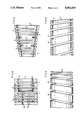
- FIG. 1is a front view showing a spring of a first embodiment of the present invention.
- FIG. 2is a front view showing the spring to which a compressive force has been applied.
- FIG. 3is a front view showing the spring to which a tensile force has been applied.
- FIG. 4is a front view showing the spring to which a bending force has been applied.
- FIG. 5is a front view showing a modification of the spring of the first embodiment.
- FIG. 6is a sectional view showing another modification of the spring of the first embodiment.
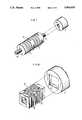
- FIG. 7is a perspective view showing a spring of a second embodiment of the present invention together with a movable member.
- FIG. 8is a perspective view showing a spring of a third embodiment of the present invention together with another movable member.
- FIG. 9is a front view showing a spring of a fourth embodiment of the present invention.
- FIG. 10is a cross sectional view of the spring.
- FIG. 11is a front view showing a spring of a fifth embodiment of the present invention.
- FIG. 12is a cross sectional view taken along the line 12--12 of FIG. 11.
- a spring 1 made from aluminumhas a solid cylindrical shape.
- a plurality of slits 2are formed on the spring 1 and extend in the radial direction. They are parallel to each other and arranged along the axis of the spring 1. They may be made by cutting operation of a metal slitting saw.
- Phases of first and second slits 2a and 2bare shifted 180 degrees in angle to each other.
- Phases of third and fourth slits 2c and 2d, fifth and sixth slits 2e and 2f, seventh and eighth slits 2g and 2hare respectively shifted 180 degrees to each other as well.
- phases of the second and third slits 2b and 2care shifted 90 degrees to each other.
- Phases of the fourth and fifth slits 2d and 2e, and the sixth and seventh slits 2f and 2gare also respectively shifted 90 degrees to each other.
- Each slit 2extends deeply in the radial direction, from one end (an opening 2x) to the other end (a closed portion 2y), and crosses the axis of the spring 1.
- An elastic portion 3 of thin plateis defined between two adjacent slits 2, respectively. Two adjacent elastic portions 3 are connected to each other by means of one of the closed portions 2y. Widths of the slits 2 are all set the same, but pitches of the first to fourth slits 2a to 2d are set larger than those of the fourth to eighth slits 2d to 2h. Accordingly, each of left side elastic portions 3a formed between the first to fourth slits 2a to 2d is thicker than each of right side elastic portions 3b formed between the fourth to eighth slits 2d to 2h.
- the right side elastic portions 3bdeflect more easily than the left side elastic portions 3a.
- the right side elastic portions 3bdeflect first so as to change the widths of the slits 2d to 2h.
- the left side elastic portions 3abegin deflecting to change the widths of the slits 2a to 2c when the right side elastic portions 3b stops deflecting any more after superceding the critical point of deflection.
- the force required to elastically deform the spring 1is small at first, and becomes large thereafter. Consequently, the relationship does not change linearly between the external force applied to the spring 1 and the distortion factor thereof, so that its elasticity characteristics become non-linear.
- the right side elastic portions 3bare deformed first and make the intervals therebetween or the widths of the slits 2d to 2h narrower gradually at the openings 2x than at the closed portions 2y. Then, the left side portions 3a are distorted to narrow the slits 2a to 2c after the right side elastic portions 3b come to be no more distorted beyond the critical point of distortion. Thereby, the spring 1 as a whole is compressed in the axial direction. In this case, the spring 1 operates as a compression spring.
- the right side elastic portions 3bwhen torsional force is applied to twist both ends of the spring 1 in circumferentially opposite directions, the right side elastic portions 3b are deformed first to change the intervals therebetween or the widths of the slits 2d to 2h. Then, the left side portions 3a are distorted to change the widths of the slits 2a to 2c after the right side elastic portions 3b come to be no more distorted beyond the critical point of distortion. Thereby, the spring 1 as a whole is twisted in the circumferential direction. In this case, the spring 1 operates as a torsion spring.
- the spring 1 of the present embodimentcan be produced only by forming the slits 2 via cutting operation, so that its manufacturing work is very easy.
- Elastic strength of the elastic portions 3is easily varied by changing the pitches of the slits 2 or the diameter of the spring 1. Therefore, the elasticity coefficient of the spring 1 can be optionally set. For instance, if the pitches of some of the slits 2 are made larger, the elastic portions which correspond to these become thicker. Thus, these elastic portions 3 are made harder to be distorted, so that there is easily provided a spring which has non-linear elasticity characteristics with high elasticity coefficient at those elastic portions 3. Namely, the elasticity characteristics of the spring 1 become non-linear only by changing the pitches of the slits 2.
- the spring 1it is very easy to manufacture the spring 1, since it is able to be produced only by cutting a base material of solid cylindrical shape.
- the spring 1 of the first embodimentis made of the base material of solid cylindrical shape.
- another springcan be produced by forming slits on a base material of cylindrical shape with a through hole. In this case, a cutting amount for making the slits become less by the extent of the through hole, so that this manufacturing work is much easier.
- the spring 1 of the first embodimenthas the pitches of slits 2 changed. Besides, as shown in FIG. 5, it may have two kinds of through holes 7a and 7b of different diameters while having the same pitches of slits 2. These holes 7a and 7b extend along the axis and communicate with each other. Thus, the wall thickness of the elastic portions 6a at one side (right side in FIG. 5) is smaller than that of the elastic portions 6b at the other side (left side in FIG. 5).
- the elastic portions 6aare easier to be distorted because of the smaller thickness than the other elastic portions 6a that have large thickness. As a result, the elastic characteristics of the spring 1 become non-linear.
- a spring 8 shown in FIG. 6has a truncated cone pipe shape. It has elastic portions 10 with the same wall thickness. Pitches of slits 9 are fixed. In this case, the elastic portions 10 with larger diameter are easier to be distorted. Thus, the elasticity characteristics of the spring 8 is non-linear.
- a spring of a second embodiment of the present inventionwill be described with reference to FIG. 7.
- a spring 15 of the second embodimentis produced by forming external threads 16 integrally at both ends of the spring 1 of the first embodiment.
- the external threads 16constitute fitting portions.
- the spring 15is disposed betweed a pair of movable members 17, only one of which is shown. These two members are adapted to approach and separate each other.
- the spring 15has both the external threads 16 inserted and fitted into internal threads 18 of the movable members 17 so as to serve to buffer the approaching and separating motion of the movable members 17.
- the external threads 16are formed integrally with the spring 15 in order to connect and fix the spring 16 and movable members 17 to each other. Therefore, the external threads 16 are hard to break even when a large load is applied to the spring 15. Also, it is easily and surely realized to connect and fix the spring 15 and movable members 17 to each other.
- the external threadsare provided on the spring 15 while the internal threads 18 are provided on the movable members 17.
- internal threadsmay be arranged on a spring while external threads be disposed on movable members. Further, only one external thread may be provided on one end of a spring as desired.
- a spring of a third embodiment of the present inventionwill be described with reference to FIG. 8.
- a spring 19has the same structure as the spring 1 of the first embodiment except that it has a square pipe shape. Slits 20 have the same pitches and widths as the slits 2 of the first embodiment.
- the spring 19is manufactured by cutting a base material of square shape with a length on which the slits 20 have been previously formed.
- the spring 19 of the third embodimentis disposed between a pair of movable members 21, only one of which is illustrated. They are arranged at a predetermined interval and reciprocally rotated in opposite directions to each other about their axis of them.
- the spring 19has both ends inserted into and engaged with engaging recesses 22 of square shape formed on the movable members 21, respectively, so as to serve to buffer reciprocating rotation thereof.
- the spring 19 of the third embodimentcan be firmly fitted to the movable members 21 only by inserting and engaging the ends into the engaging recesses 22 of the movable members 21, while being prevented from rotating relative thereto.
- the spring 19is hard to break at the ends thereof.
- a through hole of square shapemay be made on each of the movable members 21 instead of the engaging recesses 22 so that the both ends of the spring 19 be inserted and fitted thereinto.
- the springmay have a triangular or hexagonal pipe shape, and engaging recesses may have shapes corresponding thereto.
- the springs 1, 4, 8, 15 and 19 in the first to third embodimentshave the phase angles of the slits 2, 5, 9 and 20 set at 90 degrees or 180 degrees. However, these phase angles may be optionally changed as desired.
- FIGS. 9 and 10A fourth embodiment of the present invention will be described with reference to FIGS. 9 and 10.
- a spring 23is made of aluminum and has a cylindrical shape with a through hole 24 extending along its axis.
- a slit 25 of constant widthis formed on the spring 23 and extends spirally about the axis of the spring 23. It communicates with the through hole 24.
- a continuous elastic portion 26is defined by the slit 25 and extends also spirally about the axis of the spring 23. Pitches of the slit 25 are made smaller at the right end than at the left end of the spring 23 in FIGS. 9 or 10. Thus, the elastic portion 26 is easier to be distorted at the right end.
- the elastic portion 26starts being elastically deformed from the right end which has a smaller width.
- the deformed portionmoves to the left step by step, whereby the right side of the elastic portion 26 stops being distorted.
- the force necessary for elastically deforming the spring 23is small at first, but becomes greater gradually.
- the relationshipdoes not change linearly between the external force applied to the spring 23 and the distortion factor thereof.
- the elastic characteristicscan be non-linear only by optionally changing the pitches of the slit 25.
- the elasticity characteristicscan be easily varied.
- the spring 23 of the fourth embodimenthas the pitches of slit 25 changed along the axis.
- the width of the elastic portionmay be changed, e.g. by changing the width of the slit while the pitches of slit remain the same.
- a spring of a fifth embodiment of the present inventionwill be described with reference to FIGS. 11 and 12.
- a spring 20is made of aluminum and has a solid cylindrical shape.
- a plurality of slits 31 to 36are formed on the spring 30, for instance by cutting operation of a metal slitting saw C. They extend in the radial direction and are parallel to each other. They are also arranged along the axis of the spring 30 at a predetermined interval.
- Each of the slits 31 to 36comprises a pair of slitting portions 31a and 31b, 32a and 32b, 33a and 33b, 34a and 34b, 35a and 35b, and 36a and 36b.
- Each pairare formed from opposite directions with the axis therebetween in a plane orthogonally crossing the axis. Namely, the phases of the slitting portions in each pair are shifted 180 degrees in angle. The two slitting portions in the pair communicate with each other near the axis of the spring 30. The phases of the adjacent pairs are shifted 90 degrees to each other.
- Elastic portions 43 to 47 of disc shapeare formed between two adjacent slits 31 to 36, respectively. Widths of the elastic portions 43 to 47 and pitches of the slits 31 to 36 are so set as to make non-linear the elasticity characteristics of the spring as a whole. Two adjacent ones of the elastic portions 43 to 47 are connected with each other by means of each pair of connecting portions 37 to 42, which are formed at both ends of a border between each pair of slitting portions 31a to 36b. When an external force is applied to the spring 30, each of the elastic portions 43 to 47 is elastically distorted.
- a base material of solid cylindrical shapeis placed horizontally.
- the metal slitting saw C of disc shapeis cut into the base material from one outer peripheral surface toward the axis thereof. It is stopped at a position (shown by a two dot chain line at the upper side of FIG. 12) where a tip of the metal slitting saw C goes a little beyond the axis of the base material.
- the slitting portion 31ais formed at one side of the material with an arc shape inside the material.
- the positioning relationshipsare changed between the base material and the metal slitting saw C.
- an other outer peripheral surfacewhich is opposite to the one peripheral surface in the cutting of the slitting portion 31a, is moved to face the metal slitting saw C. Thereafter, the metal slitting saw C is operated to cut into the base material from the other peripheral surface toward the axis thereof. The saw C is stopped at a position (shown by another two dot chain line at the lower side of FIG. 12) where a tip of the metal slitting saw C goes a little beyond the axis of the base material.
- the slitting portion 31bis thus formed in the same plane as the slitting portion 31a thereby constituting a pair. Thereby, a pair of connecting portions 37 are left without being cut, so that the first slit 31 is formed.
- the metal slitting saw Cis transposed a fixed distance along the axis from the first slit 31 to a position to be cut next. For example, it is moved rightward in FIG. 11. The saw C is then shifted 90 degrees in angle from the first slit 31 and cut into the base material at that position in the same manner as the formation of the first slit 31. Thus the slitting portion 32a is formed. Then, the metal saw C is again cut into the base material from the opposite side to the slitting portion 32a, thereby making the slitting portion 32b. Thus, the second slit 32 is formed while a pair of second connecting portions 39 to 42 remain uncut.
- the third to sixth slits 33 to 36 and the third to sixth connecting portions 39 to 42are formed. According to the above operation, the elastic portions 43 to 47 are formed between the slits 31 to 36, thus completing the manufacturing the spring 30.
- the spring 30 of the fifth embodimentis able to be easily manufactured only by forming the slits 31 to 36 with cutting operations as in the first embodiment.
- Elastic strength of the elastic portions 43 to 47is changed as the pitches of the slits 31 to 36 and the dimaters of the spring 30 are changed. So the elasticity characteristics of the spring 30 can be easily changed corresponding to conditions required in desired cases.
- a material of the springs 1, 4, 8, 15, 19, 23 and 30 of the above embodimentsis not limited to aluminum, but for instance steel, synthetic resin or the like may be used.
- the springs 1, 4, 8, 15, 19, 23 and 30may also be used in a variety of machines or apparatus, e.g. cutting machines, measuring machines, etc. Besides, they may be applicable to, for example, signets.
- slits like those of the first embodimentare made at the perimeter near a pressing surface where a seal impression is formed. With this signet, elastic portions defined between the slits are deformed at use when the surface is not parallel to a paper surface. Thus, the signet is always able to get the pressing surface to come into firm contact with a paper surface thereby making a clear seal impression.
Landscapes
- Engineering & Computer Science (AREA)
- General Engineering & Computer Science (AREA)
- Mechanical Engineering (AREA)
- Springs (AREA)
Abstract
Description
The present invention relates generally to a spring and its manufacturing method, particular to a spring and its manufacturing method in which slits are formed on a block of base material.
In general, a linear member as a base material is wound spirally to form a coil spring. In producing springs with non-linear elasticity characteristics, winding pitches and diameters of the linear member are changed according to the characteristics desired. However, this work is time-consuming and manufacturing costs will increase, so that product prices of the springs are pushed high.
On the other hand, when the spring is used as a tension spring and/or a torsion spring, its ends are bent in U-shape to form a hook, which is hooked or attached to an object. But, with this way of hooking, when a heavy load is applied to the hook, it might be unable to bear the load and be broken.
A flexible coupling, though not a spring, is discosed in Japanese Patent Publication No. 58-49732 which was laid open on Apr. 9, 1975, and announced to be granted on Nov. 7, 1983. It corresponds to U.S. Pat. No. 3,844,137. The coupling has the same operation as a spring in that both of them have elasticity. The coupling comprises a plurality of pairs of slits which are formed into a cylindrical main body. They have depths larger than the radius of the main body. They are arranged at the same pitch along the axis of the main body. Plate spring portions are defined respectively between one pair of the slits, respectively, and have the same width. Each pair has two slits extended in parallel with each other and from the opposite directions. The extending directions of each pair are shifted at the angle of 90 degrees compared with those of the adjacent pair.
It is a primary objective of the present invention to provide a spring which has non-linear elasticity characteristics and is easily manufactured to lower the product prices, and its manufacturing method.
It is another objective of the present invention to provide a spring which can be firmly attached to an object and has its fitting portion strong enough to bear a large load and be prevented from breaking.
In order to achieve the above and other objectives, in accordance with the first aspect of the present invention, a spring with a length is disclosed that has a plurality of slits formed thereon. The slits are placed at longitudinally different positions. They extend from the outer peripheral surface to the inside while substantially in parallel to one another. A plurality of elastic portions are defined between two adjacent slits, respectively. Some of the elastic portions have a elastic coefficient different from that of the others so that the spring has non-linear elasticity characteristics.
The spring may have a solid cylindrical shape. A fitting portion attachable to an object may be integrally formed at one longitudinal end thereof. The spring also may have a polygonal shape and one longitudinal end thereof be inserted into and engaged with a recess which is formed on an object while being restricted from rotation relative to the object.
Also, each slit may be composed of a pair of slitting portions which extend from opposite surfaces toward the axis of the spring in the same plane substantially orthogonally crossing the axis. They communicate with each other near the axis. In the same plane, a pair of connecting portions may be arranged, at a border of the two slitting portions of the pair, on the outer periphery of the spring in order to connect the adjacent elastic portions.
A method for manufacturing a spring in accordance with the present invention comprises a first step for making a metal slitting saw cut into a base material from a first outer surface toward an axis thereof, in a plane substantially orthogonally crossing the axis. In the first step, the metal slitting saw is stopped at a first radial position beyond the axis. It has a second step for making the metal slitting saw cut into the base material from a second outer surface, which is opposite to the first outer surface, toward the axis thereof, in the same plane. In the second step, the metal slitting saw is stopped at a second radial position beyond the axis. Thus, a pair of slitting portions are formed and communicate each other near the axis while a pair of connecting portions are formed, at a border of the two slitting portions of the pair, on an outer periphery of the base material. In a third step, the metal slitting saw has its cutting position transposed along the axis of the base material relative thereto. The above first to third steps, are repeated so that a plurality of elastic portions are defined between the slitting portions and connected by the connecting portions.
A spring is disclosed, according to a second aspect of the present invention, that has a cylindrical shape with a through hole extending along its axis. A line of slit extends spirally about the axis and communicates with the through hole. An elastic portion is defined by the slit and also extend spirally about the axis. The width of the elastic portion changes along the axis.
A spring is disclosed, according to a third aspect of the present invention, that comprises a plurality of slits cut into the spring from an outer peripheral surface to an inside thereof. A plurality of elastic portions are defined by the slits so that some of them have an elasticity coefficient different from that of the others, whereby the spring have non-linear elasticity characteristics.
Other and further objectives of the present invention will become apparent with an understanding of the embodiments discussed later, and the appended claims. Further, many advantages not mentioned in this specification will become obvious to one skilled in the art upon application of the present invention.
FIG. 1 is a front view showing a spring of a first embodiment of the present invention.
FIG. 2 is a front view showing the spring to which a compressive force has been applied.
FIG. 3 is a front view showing the spring to which a tensile force has been applied.
FIG. 4 is a front view showing the spring to which a bending force has been applied.
FIG. 5 is a front view showing a modification of the spring of the first embodiment.
FIG. 6 is a sectional view showing another modification of the spring of the first embodiment.
FIG. 7 is a perspective view showing a spring of a second embodiment of the present invention together with a movable member.
FIG. 8 is a perspective view showing a spring of a third embodiment of the present invention together with another movable member.
FIG. 9 is a front view showing a spring of a fourth embodiment of the present invention.
FIG. 10 is a cross sectional view of the spring.
FIG. 11 is a front view showing a spring of a fifth embodiment of the present invention.
FIG. 12 is a cross sectional view taken along theline 12--12 of FIG. 11.
A spring of a first embodiment of the present invention will be described hereafter referring to FIGS. 1 to 4.
As shown in FIG. 1, aspring 1 made from aluminum has a solid cylindrical shape. A plurality ofslits 2 are formed on thespring 1 and extend in the radial direction. They are parallel to each other and arranged along the axis of thespring 1. They may be made by cutting operation of a metal slitting saw. Phases of first andsecond slits fourth slits sixth slits eighth slits 2g and 2h are respectively shifted 180 degrees to each other as well. On the other hand, phases of the second andthird slits fifth slits seventh slits 2f and 2g are also respectively shifted 90 degrees to each other.
Eachslit 2 extends deeply in the radial direction, from one end (anopening 2x) to the other end (aclosed portion 2y), and crosses the axis of thespring 1. Anelastic portion 3 of thin plate is defined between twoadjacent slits 2, respectively. Two adjacentelastic portions 3 are connected to each other by means of one of theclosed portions 2y. Widths of theslits 2 are all set the same, but pitches of the first tofourth slits 2a to 2d are set larger than those of the fourth toeighth slits 2d to 2h. Accordingly, each of left sideelastic portions 3a formed between the first tofourth slits 2a to 2d is thicker than each of right sideelastic portions 3b formed between the fourth toeighth slits 2d to 2h. As a result, the right sideelastic portions 3b deflect more easily than the left sideelastic portions 3a. When external force is applied to thespring 1, the right sideelastic portions 3b deflect first so as to change the widths of theslits 2d to 2h. The left sideelastic portions 3a begin deflecting to change the widths of theslits 2a to 2c when the right sideelastic portions 3b stops deflecting any more after superceding the critical point of deflection. The force required to elastically deform thespring 1 is small at first, and becomes large thereafter. Consequently, the relationship does not change linearly between the external force applied to thespring 1 and the distortion factor thereof, so that its elasticity characteristics become non-linear.
There will be described operations of thespring 1 constructed as above wherein various kinds of external force are applied thereto.
As shown in FIG. 2, when compressive force is applied to thespring 1 in the axial direction thereof, the right sideelastic portions 3b are deformed first and make the intervals therebetween or the widths of theslits 2d to 2h narrower gradually at theopenings 2x than at theclosed portions 2y. Then, theleft side portions 3a are distorted to narrow theslits 2a to 2c after the right sideelastic portions 3b come to be no more distorted beyond the critical point of distortion. Thereby, thespring 1 as a whole is compressed in the axial direction. In this case, thespring 1 operates as a compression spring.
On the contrary, as shown in FIG. 3, when tensile force is applied to thespring 1 in the axial direction thereof, the right sideelastic portions 3b are deformed first and make the intervals therebetween or the widths of theslits 2d to 2h wider gradually at theopenings 2x than at theclosed portions 2y. Then, theleft side portions 3a are distorted to widen theslits 2a to 2c after the right sideelastic portions 3b come to be no more distorted beyond the critical point of distortion. Thereby, thespring 1 as a whole is elongated in the axial direction. In this case, thespring 1 operates as a tension spring.
On the other hand, as shown in FIG. 4, when bending force is applied to both ends of thespring 1, the right sideelastic portions 3b are deformed first and make the intervals therebetween or the widths of theslits 2d to 2h wider gradually at the upper portion than at the lower portions. Then, theleft side portions 3a are distorted to widen theslits 2a to 2c after the right sideelastic portions 3b come to be no more distorted beyond the critical point of distortion. Thereby, thespring 1 as a whole is bent in the radial direction. In this case, thespring 1 operates as a bend spring.
In addition, though not shown in the drawings, when torsional force is applied to twist both ends of thespring 1 in circumferentially opposite directions, the right sideelastic portions 3b are deformed first to change the intervals therebetween or the widths of theslits 2d to 2h. Then, theleft side portions 3a are distorted to change the widths of theslits 2a to 2c after the right sideelastic portions 3b come to be no more distorted beyond the critical point of distortion. Thereby, thespring 1 as a whole is twisted in the circumferential direction. In this case, thespring 1 operates as a torsion spring.
As described above, thespring 1 of the present embodiment can be produced only by forming theslits 2 via cutting operation, so that its manufacturing work is very easy. Elastic strength of theelastic portions 3 is easily varied by changing the pitches of theslits 2 or the diameter of thespring 1. Therefore, the elasticity coefficient of thespring 1 can be optionally set. For instance, if the pitches of some of theslits 2 are made larger, the elastic portions which correspond to these become thicker. Thus, theseelastic portions 3 are made harder to be distorted, so that there is easily provided a spring which has non-linear elasticity characteristics with high elasticity coefficient at thoseelastic portions 3. Namely, the elasticity characteristics of thespring 1 become non-linear only by changing the pitches of theslits 2.
In addition, it is very easy to manufacture thespring 1, since it is able to be produced only by cutting a base material of solid cylindrical shape.
Thespring 1 of the first embodiment is made of the base material of solid cylindrical shape. However, for example, another spring can be produced by forming slits on a base material of cylindrical shape with a through hole. In this case, a cutting amount for making the slits become less by the extent of the through hole, so that this manufacturing work is much easier.
Thespring 1 of the first embodiment has the pitches ofslits 2 changed. Besides, as shown in FIG. 5, it may have two kinds of throughholes 7a and 7b of different diameters while having the same pitches ofslits 2. Theseholes 7a and 7b extend along the axis and communicate with each other. Thus, the wall thickness of theelastic portions 6a at one side (right side in FIG. 5) is smaller than that of theelastic portions 6b at the other side (left side in FIG. 5).
In this case, theelastic portions 6a are easier to be distorted because of the smaller thickness than the otherelastic portions 6a that have large thickness. As a result, the elastic characteristics of thespring 1 become non-linear.
A spring 8 shown in FIG. 6 has a truncated cone pipe shape. It haselastic portions 10 with the same wall thickness. Pitches ofslits 9 are fixed. In this case, theelastic portions 10 with larger diameter are easier to be distorted. Thus, the elasticity characteristics of the spring 8 is non-linear.
A spring of a second embodiment of the present invention will be described with reference to FIG. 7.
Aspring 15 of the second embodiment is produced by formingexternal threads 16 integrally at both ends of thespring 1 of the first embodiment. Theexternal threads 16 constitute fitting portions.
Thespring 15 is disposed betweed a pair ofmovable members 17, only one of which is shown. These two members are adapted to approach and separate each other. Thespring 15 has both theexternal threads 16 inserted and fitted intointernal threads 18 of themovable members 17 so as to serve to buffer the approaching and separating motion of themovable members 17.
As described above, theexternal threads 16 are formed integrally with thespring 15 in order to connect and fix thespring 16 andmovable members 17 to each other. Therefore, theexternal threads 16 are hard to break even when a large load is applied to thespring 15. Also, it is easily and surely realized to connect and fix thespring 15 andmovable members 17 to each other.
In the second embodiment, the external threads are provided on thespring 15 while theinternal threads 18 are provided on themovable members 17. Besides, internal threads may be arranged on a spring while external threads be disposed on movable members. Further, only one external thread may be provided on one end of a spring as desired.
A spring of a third embodiment of the present invention will be described with reference to FIG. 8.
Aspring 19 has the same structure as thespring 1 of the first embodiment except that it has a square pipe shape.Slits 20 have the same pitches and widths as theslits 2 of the first embodiment. Thespring 19 is manufactured by cutting a base material of square shape with a length on which theslits 20 have been previously formed.
Thespring 19 of the third embodiment is disposed between a pair ofmovable members 21, only one of which is illustrated. They are arranged at a predetermined interval and reciprocally rotated in opposite directions to each other about their axis of them. Thespring 19 has both ends inserted into and engaged withengaging recesses 22 of square shape formed on themovable members 21, respectively, so as to serve to buffer reciprocating rotation thereof.
As described above, thespring 19 of the third embodiment can be firmly fitted to themovable members 21 only by inserting and engaging the ends into the engagingrecesses 22 of themovable members 21, while being prevented from rotating relative thereto. Thus, thespring 19 is hard to break at the ends thereof. In addition, it is easy to manufacture thespring 19, because it is carried out only by cutting the base material of square pipe shape. A through hole of square shape may be made on each of themovable members 21 instead of the engagingrecesses 22 so that the both ends of thespring 19 be inserted and fitted thereinto. Moreover, the spring may have a triangular or hexagonal pipe shape, and engaging recesses may have shapes corresponding thereto.
Thesprings slits
A fourth embodiment of the present invention will be described with reference to FIGS. 9 and 10.
Aspring 23 is made of aluminum and has a cylindrical shape with a throughhole 24 extending along its axis. A slit 25 of constant width is formed on thespring 23 and extends spirally about the axis of thespring 23. It communicates with the throughhole 24. A continuouselastic portion 26 is defined by theslit 25 and extends also spirally about the axis of thespring 23. Pitches of theslit 25 are made smaller at the right end than at the left end of thespring 23 in FIGS. 9 or 10. Thus, theelastic portion 26 is easier to be distorted at the right end.
When various external forces in the first embodiment are applied to thespring 23 constructed as above, theelastic portion 26 starts being elastically deformed from the right end which has a smaller width. The deformed portion moves to the left step by step, whereby the right side of theelastic portion 26 stops being distorted. Thus, the force necessary for elastically deforming thespring 23 is small at first, but becomes greater gradually. As a result, the relationship does not change linearly between the external force applied to thespring 23 and the distortion factor thereof. In other words, the elastic characteristics can be non-linear only by optionally changing the pitches of theslit 25. The elasticity characteristics can be easily varied.
Thespring 23 of the fourth embodiment has the pitches ofslit 25 changed along the axis. However, the width of the elastic portion may be changed, e.g. by changing the width of the slit while the pitches of slit remain the same.
A spring of a fifth embodiment of the present invention will be described with reference to FIGS. 11 and 12.
Aspring 20 is made of aluminum and has a solid cylindrical shape. A plurality ofslits 31 to 36 are formed on thespring 30, for instance by cutting operation of a metal slitting saw C. They extend in the radial direction and are parallel to each other. They are also arranged along the axis of thespring 30 at a predetermined interval. Each of theslits 31 to 36 comprises a pair of slittingportions spring 30. The phases of the adjacent pairs are shifted 90 degrees to each other.
A manufacturing method of thespring 30 will be described hereafter.
First, as shown in FIG. 12, a base material of solid cylindrical shape is placed horizontally. Then, the metal slitting saw C of disc shape is cut into the base material from one outer peripheral surface toward the axis thereof. It is stopped at a position (shown by a two dot chain line at the upper side of FIG. 12) where a tip of the metal slitting saw C goes a little beyond the axis of the base material. Thus, the slittingportion 31a is formed at one side of the material with an arc shape inside the material. Second, the positioning relationships are changed between the base material and the metal slitting saw C. Then, an other outer peripheral surface, which is opposite to the one peripheral surface in the cutting of the slittingportion 31a, is moved to face the metal slitting saw C. Thereafter, the metal slitting saw C is operated to cut into the base material from the other peripheral surface toward the axis thereof. The saw C is stopped at a position (shown by another two dot chain line at the lower side of FIG. 12) where a tip of the metal slitting saw C goes a little beyond the axis of the base material. The slittingportion 31b is thus formed in the same plane as the slittingportion 31a thereby constituting a pair. Thereby, a pair of connectingportions 37 are left without being cut, so that thefirst slit 31 is formed.
Then, the metal slitting saw C is transposed a fixed distance along the axis from thefirst slit 31 to a position to be cut next. For example, it is moved rightward in FIG. 11. The saw C is then shifted 90 degrees in angle from thefirst slit 31 and cut into the base material at that position in the same manner as the formation of thefirst slit 31. Thus the slittingportion 32a is formed. Then, the metal saw C is again cut into the base material from the opposite side to the slittingportion 32a, thereby making the slittingportion 32b. Thus, thesecond slit 32 is formed while a pair of second connectingportions 39 to 42 remain uncut. In the same way as above, the third tosixth slits 33 to 36 and the third to sixth connectingportions 39 to 42 are formed. According to the above operation, theelastic portions 43 to 47 are formed between theslits 31 to 36, thus completing the manufacturing thespring 30.
As described above, thespring 30 of the fifth embodiment is able to be easily manufactured only by forming theslits 31 to 36 with cutting operations as in the first embodiment.
Elastic strength of theelastic portions 43 to 47 is changed as the pitches of theslits 31 to 36 and the dimaters of thespring 30 are changed. So the elasticity characteristics of thespring 30 can be easily changed corresponding to conditions required in desired cases.
A material of thesprings
Thesprings
As many apparently widely different embodiments of this invention may be made without departing from the spirit and scope thereof, it is to be understood that the invention is not limited to the specific embodiments thereof except as defined in the appended claims.
Claims (7)
1. A spring comprising:
an elongated spring body having a longitudinal axis;
a plurality of substantially parallel slits extending laterally through the spring body, each said slit extending more than half way through the spring body, the slits being arranged in sets, each set having at least two pairs of slits oriented at different phase angles, wherein the individual slits in each slit pair are angularly displaced substantially 180° relative to one another; and
a plurality of elastic portions respectively defined between adjacent slits, wherein the thicknesses of the elastic portions in a first set is different from the thicknesses of the elastic portions in a second set to provide the spring with a non-linear elasticity characteristic.
2. A spring as recited in claim 1, wherein within each set, the orientation of a first pair of said slits is angularly displaced substantially 90° relative to a second pair of said slits.
3. A spring as recited in claim 1, wherein the thicknesses of the elastic portions formed between the slits in each particular set of slits are the same.
4. A spring as recited in claim 1, wherein the spring body is formed from a tubular member.
5. A spring as recited in claim 4, wherein said spring body is substantially cylindrical.
6. A spring as recited in claim 4, wherein said spring body has a substantially rectangular cross-section.
7. A spring comprising:
an elongated spring body having a longitudinal axis;
a plurality of substantially parallel slits extending laterally through the spring body, each said slit extending more than half way through the spring body, the slits being arranged in at least two sets of at least four slits oriented at different phase angles the four slits within each set being oriented at substantially 90° intervals; and
a plurality of elastic portions respectively defined between adjacent slits, wherein the thicknesses of the elastic portions formed between the slits in each particular set of slits are the same, and wherein the thicknesses of the elastic portions formed between the slits in a first set of slits are different from the thicknesses of the elastic portions formed between the slits in a second set of slits to provide the spring with a non-linear elasticity characteristic.
Applications Claiming Priority (4)
| Application Number | Priority Date | Filing Date | Title |
|---|---|---|---|
| JP3946189 | 1989-04-03 | ||
| JP1-39461[U] | 1989-04-03 | ||
| JP1197408AJPH07117110B2 (en) | 1989-04-03 | 1989-07-29 | spring |
| JP1-197408 | 1989-07-29 |
Publications (1)
| Publication Number | Publication Date |
|---|---|
| US5062619Atrue US5062619A (en) | 1991-11-05 |
Family
ID=26378857
Family Applications (1)
| Application Number | Title | Priority Date | Filing Date |
|---|---|---|---|
| US07/502,489Expired - LifetimeUS5062619A (en) | 1989-04-03 | 1990-03-30 | Non-linear spring |
Country Status (1)
| Country | Link |
|---|---|
| US (1) | US5062619A (en) |
Cited By (46)
| Publication number | Priority date | Publication date | Assignee | Title |
|---|---|---|---|---|
| US5213436A (en)* | 1990-08-02 | 1993-05-25 | Anschutz & Co. Gmbh | Spring joint for pivotally connecting two bodies |
| US5299980A (en)* | 1992-06-24 | 1994-04-05 | Nordex Inc. | Constant velocity flexible coupling and connection with the drive and driven members |
| US5521446A (en)* | 1994-03-24 | 1996-05-28 | Fluid Systems Partners Sa | Linear electromagnetic drive means |
| GB2297140A (en)* | 1995-01-19 | 1996-07-24 | John Hopkins | Spring; hand exerciser |
| US5558393A (en)* | 1995-01-24 | 1996-09-24 | Proteus Engineering, Inc. | Composite multi-wave compression spring |
| US6068250A (en)* | 1996-09-23 | 2000-05-30 | Proteus Engineering Inc. | Composite multi-wave compression spring |
| US6203437B1 (en)* | 1996-08-30 | 2001-03-20 | Reliance Gear Company Limited | Flexible coupling |
| FR2805868A1 (en)* | 2000-03-02 | 2001-09-07 | Peugeot Citroen Automobiles Sa | Elastic component such as compression spring used in vehicle manufacture is made from cylinder of flexible material with series of transverse slots |
| US6612556B2 (en) | 2001-04-30 | 2003-09-02 | Cornell Research Foundation, Inc. | Multihelical composite spring |
| US20030190185A1 (en)* | 2002-04-04 | 2003-10-09 | The Swatch Group Management Services Ag | Locking member and device |
| US20040037626A1 (en)* | 2002-08-26 | 2004-02-26 | Shorya Awtar | Mechanisms having motion with constrained degrees of freedom |
| US20040061412A1 (en)* | 2002-09-26 | 2004-04-01 | Japan Servo Co., Ltd. | Brush type small motor having non-linear spring device |
| US20050049051A1 (en)* | 2001-06-28 | 2005-03-03 | Pinard Adam I. | Lead screw coupling |
| US20050178934A1 (en)* | 2001-06-15 | 2005-08-18 | Trumpf Lasertechnik Gmbh | Articulated bearing supports for laser resonators |
| US20050203519A1 (en)* | 2004-03-09 | 2005-09-15 | Jurgen Harms | Rod-like element for application in spinal or trauma surgery, and stabilization device with such a rod-like element |
| US20050224604A1 (en)* | 2002-03-26 | 2005-10-13 | Dietmar Uhlmann | Fuel injection valve |
| US20060276247A1 (en)* | 2005-06-03 | 2006-12-07 | Martinez Jaime E | Flexible shaft |
| US20070021718A1 (en)* | 2005-05-24 | 2007-01-25 | Stefan Burren | Plastic spring |
| US7195584B1 (en) | 2004-07-20 | 2007-03-27 | Brunswick Corporation | Exercise apparatus for resistance training |
| WO2008014759A1 (en)* | 2006-07-28 | 2008-02-07 | Epcos Ag | Spring element and piezoelectric actuator with the spring element |
| US20090076614A1 (en)* | 2007-09-17 | 2009-03-19 | Spinalmotion, Inc. | Intervertebral Prosthetic Disc with Shock Absorption Core |
| US20090267276A1 (en)* | 2005-02-18 | 2009-10-29 | Kabushiki Kaisha Kobe Seiko Sho | Vibration Reducing Bracket |
| US20100230877A1 (en)* | 2009-03-13 | 2010-09-16 | Gm Global Technology Operations, Inc. | Vehicular impact bumper assembly |
| US7824270B2 (en) | 2007-01-23 | 2010-11-02 | C-Flex Bearing Co., Inc. | Flexible coupling |
| US20110169205A1 (en)* | 2010-01-08 | 2011-07-14 | Stephen Kempf | Plastic Spring And Method And Apparatus For Making The Same |
| WO2011113695A1 (en) | 2010-03-15 | 2011-09-22 | Aktiebolaget Skf | Device for braking and/or blocking a shaft, and method for producing a device of said type |
| US20110298167A1 (en)* | 2007-08-08 | 2011-12-08 | Kopp John D | Control stick adapted for use in a fly-by-wire flight control system, and linkage for use therein |
| US20130017075A1 (en)* | 2006-10-30 | 2013-01-17 | Schlumberger Technology Corporation | Electrical Submersible Pump |
| US20130126641A1 (en)* | 2011-11-22 | 2013-05-23 | Delavan Inc | Machined springs for injector applications |
| CN103883656A (en)* | 2014-04-17 | 2014-06-25 | 植健 | Novel Z-shaped spring |
| US20140228132A1 (en)* | 2011-10-07 | 2014-08-14 | Ringfeder Power-Transmission Gmbh | Compensating coupling for transmitting torques |
| US8882089B2 (en) | 2012-08-17 | 2014-11-11 | Itt Manufacturing Enterprises Llc | Dual radius isolator |
| US20150060433A1 (en)* | 2013-08-29 | 2015-03-05 | Varian Semiconductor Equipment Associates, Inc. | High temperature platen power contact |
| US20180142751A1 (en)* | 2016-11-17 | 2018-05-24 | Grammer Ag | Spring |
| US20180209504A1 (en)* | 2015-07-16 | 2018-07-26 | Hyung Woo Kim | Spring structure having multiple coil-shaped unit springs and method for manufacturing same |
| US20180214899A1 (en)* | 2014-01-13 | 2018-08-02 | Silgan Dispensing Systems Corporation | Dispensing pump with skirt spring |
| US10933525B2 (en)* | 2018-07-04 | 2021-03-02 | Fanuc Corporation | Horizontal articulated robot |
| US20210288425A1 (en)* | 2018-11-30 | 2021-09-16 | Corning Optical Communications Rf Llc | Compressible electrical contacts with divericated-cut sections |
| US20220074459A1 (en)* | 2020-09-07 | 2022-03-10 | Honda Motor Co., Ltd. | Resinous spring |
| US20220349475A1 (en)* | 2021-04-28 | 2022-11-03 | Saint-Gobain Performance Plastics Corporation | Seal with radial cut torus spring |
| WO2022260566A1 (en)* | 2021-06-11 | 2022-12-15 | Välinge Innovation AB | A locking device comprising a spring and a locking pin and a set comprising furniture components and the locking device |
| US20230349950A1 (en)* | 2020-01-10 | 2023-11-02 | Nidec Read Corporation | Contact, inspection jig, inspection device, and method of manufacturing contact |
| US12176638B2 (en) | 2019-11-30 | 2024-12-24 | Corning Optical Communications RF, LLC | Connector assemblies |
| US12212083B2 (en) | 2020-11-30 | 2025-01-28 | Corning Optical Communications Rf Llc | Compressible electrical assemblies with divaricated-cut sections |
| RU2836131C1 (en)* | 2024-11-27 | 2025-03-11 | Акционерное общество "Взлет" | Electroacoustic transducer with built-in rlc-filter |
| US12404889B2 (en) | 2021-06-11 | 2025-09-02 | Välinge Innovation AB | Mechanical connection arrangement for panels |
Citations (20)
| Publication number | Priority date | Publication date | Assignee | Title |
|---|---|---|---|---|
| US1557958A (en)* | 1924-08-26 | 1925-10-20 | American Mach & Foundry | Flexible coupling |
| US1558576A (en)* | 1922-12-04 | 1925-10-27 | Westinghouse Electric & Mfg Co | Flexible coupling |
| US1943942A (en)* | 1932-01-20 | 1934-01-16 | Italiana Magneti Marelli Socie | Flexible coupling |
| US2171185A (en)* | 1935-12-18 | 1939-08-29 | Maier Friedrich Eugen | Longitudinal spring for telescopic tubular guides |
| US2343079A (en)* | 1941-12-22 | 1944-02-29 | Gen Motors Corp | Coupling |
| FR1090004A (en)* | 1953-07-22 | 1955-03-25 | Spring | |
| US2888258A (en)* | 1956-05-11 | 1959-05-26 | Hoffstrom Bo Nilsson | Springs |
| US3071941A (en)* | 1961-10-11 | 1963-01-08 | Ferroplast Th Burdelski & Co | Spindle coupling |
| US3390546A (en)* | 1966-05-13 | 1968-07-02 | Jewell Hollis | Flexible coupling member |
| US3597938A (en)* | 1969-05-21 | 1971-08-10 | Singer General Precision | Flexure joint |
| US3662648A (en)* | 1969-03-05 | 1972-05-16 | Brevets Aero Mecaniques | Elastic damping device for fire-arms |
| US3844137A (en)* | 1973-07-16 | 1974-10-29 | Cyclo Index Corp | Flexible coupling |
| DE2501397A1 (en)* | 1974-01-16 | 1975-11-27 | Montanari | CABLE-LIKE FEATHER |
| FR2271452A1 (en)* | 1974-05-13 | 1975-12-12 | Pean Pierre | Flexible coupling element - is formed by sets of circumferential slots in wall of tubular piece |
| JPS5849732A (en)* | 1981-05-18 | 1983-03-24 | Fuji Kagakushi Kogyo Co Ltd | Preparation of ink-holding porous material |
| US4690661A (en)* | 1985-08-26 | 1987-09-01 | Rexnord Inc. | Torsional stress distribution flexible coupling |
| GB2193290A (en)* | 1986-07-29 | 1988-02-03 | Ford Motor Co | Tubular spacer |
| WO1988001026A1 (en)* | 1986-07-31 | 1988-02-11 | Anthony Owen Hunt | Flexible coupling |
| US4826143A (en)* | 1985-10-22 | 1989-05-02 | U.S. Philips Corporation | Method of manufacturing a spring of the cylindrical type to be used at high temperature |
| US4858897A (en)* | 1987-11-16 | 1989-08-22 | Hideki Irifune | Spring |
- 1990
- 1990-03-30USUS07/502,489patent/US5062619A/ennot_activeExpired - Lifetime
Patent Citations (20)
| Publication number | Priority date | Publication date | Assignee | Title |
|---|---|---|---|---|
| US1558576A (en)* | 1922-12-04 | 1925-10-27 | Westinghouse Electric & Mfg Co | Flexible coupling |
| US1557958A (en)* | 1924-08-26 | 1925-10-20 | American Mach & Foundry | Flexible coupling |
| US1943942A (en)* | 1932-01-20 | 1934-01-16 | Italiana Magneti Marelli Socie | Flexible coupling |
| US2171185A (en)* | 1935-12-18 | 1939-08-29 | Maier Friedrich Eugen | Longitudinal spring for telescopic tubular guides |
| US2343079A (en)* | 1941-12-22 | 1944-02-29 | Gen Motors Corp | Coupling |
| FR1090004A (en)* | 1953-07-22 | 1955-03-25 | Spring | |
| US2888258A (en)* | 1956-05-11 | 1959-05-26 | Hoffstrom Bo Nilsson | Springs |
| US3071941A (en)* | 1961-10-11 | 1963-01-08 | Ferroplast Th Burdelski & Co | Spindle coupling |
| US3390546A (en)* | 1966-05-13 | 1968-07-02 | Jewell Hollis | Flexible coupling member |
| US3662648A (en)* | 1969-03-05 | 1972-05-16 | Brevets Aero Mecaniques | Elastic damping device for fire-arms |
| US3597938A (en)* | 1969-05-21 | 1971-08-10 | Singer General Precision | Flexure joint |
| US3844137A (en)* | 1973-07-16 | 1974-10-29 | Cyclo Index Corp | Flexible coupling |
| DE2501397A1 (en)* | 1974-01-16 | 1975-11-27 | Montanari | CABLE-LIKE FEATHER |
| FR2271452A1 (en)* | 1974-05-13 | 1975-12-12 | Pean Pierre | Flexible coupling element - is formed by sets of circumferential slots in wall of tubular piece |
| JPS5849732A (en)* | 1981-05-18 | 1983-03-24 | Fuji Kagakushi Kogyo Co Ltd | Preparation of ink-holding porous material |
| US4690661A (en)* | 1985-08-26 | 1987-09-01 | Rexnord Inc. | Torsional stress distribution flexible coupling |
| US4826143A (en)* | 1985-10-22 | 1989-05-02 | U.S. Philips Corporation | Method of manufacturing a spring of the cylindrical type to be used at high temperature |
| GB2193290A (en)* | 1986-07-29 | 1988-02-03 | Ford Motor Co | Tubular spacer |
| WO1988001026A1 (en)* | 1986-07-31 | 1988-02-11 | Anthony Owen Hunt | Flexible coupling |
| US4858897A (en)* | 1987-11-16 | 1989-08-22 | Hideki Irifune | Spring |
Cited By (73)
| Publication number | Priority date | Publication date | Assignee | Title |
|---|---|---|---|---|
| US5213436A (en)* | 1990-08-02 | 1993-05-25 | Anschutz & Co. Gmbh | Spring joint for pivotally connecting two bodies |
| US5299980A (en)* | 1992-06-24 | 1994-04-05 | Nordex Inc. | Constant velocity flexible coupling and connection with the drive and driven members |
| US5521446A (en)* | 1994-03-24 | 1996-05-28 | Fluid Systems Partners Sa | Linear electromagnetic drive means |
| GB2297140B (en)* | 1995-01-19 | 1998-04-29 | John Hopkins | Spring apparatus |
| GB2297140A (en)* | 1995-01-19 | 1996-07-24 | John Hopkins | Spring; hand exerciser |
| US5558393A (en)* | 1995-01-24 | 1996-09-24 | Proteus Engineering, Inc. | Composite multi-wave compression spring |
| US6203437B1 (en)* | 1996-08-30 | 2001-03-20 | Reliance Gear Company Limited | Flexible coupling |
| US6068250A (en)* | 1996-09-23 | 2000-05-30 | Proteus Engineering Inc. | Composite multi-wave compression spring |
| FR2805868A1 (en)* | 2000-03-02 | 2001-09-07 | Peugeot Citroen Automobiles Sa | Elastic component such as compression spring used in vehicle manufacture is made from cylinder of flexible material with series of transverse slots |
| US6612556B2 (en) | 2001-04-30 | 2003-09-02 | Cornell Research Foundation, Inc. | Multihelical composite spring |
| US20050178934A1 (en)* | 2001-06-15 | 2005-08-18 | Trumpf Lasertechnik Gmbh | Articulated bearing supports for laser resonators |
| US7316381B2 (en)* | 2001-06-15 | 2008-01-08 | Trumpf Lasertechnik Gmbh | Articulated bearing supports for laser resonators |
| US20050049051A1 (en)* | 2001-06-28 | 2005-03-03 | Pinard Adam I. | Lead screw coupling |
| US7175112B2 (en)* | 2002-03-26 | 2007-02-13 | Robert Bosch Gmbh | Fuel injection valve |
| US20050224604A1 (en)* | 2002-03-26 | 2005-10-13 | Dietmar Uhlmann | Fuel injection valve |
| US6923593B2 (en)* | 2002-04-04 | 2005-08-02 | The Swatch Group Management Services Ag | Locking member and device |
| US20030190185A1 (en)* | 2002-04-04 | 2003-10-09 | The Swatch Group Management Services Ag | Locking member and device |
| KR100950414B1 (en) | 2002-04-04 | 2010-03-31 | 더 스워치 그룹 매니지먼트 서비시스 아게 | Locking member and device |
| US20040037626A1 (en)* | 2002-08-26 | 2004-02-26 | Shorya Awtar | Mechanisms having motion with constrained degrees of freedom |
| US7362030B2 (en) | 2002-09-26 | 2008-04-22 | Japan Servo Co., Ltd. | Brush type small motor having non-linear spring device |
| US7249757B2 (en)* | 2002-09-26 | 2007-07-31 | Japan Servo Co., Ltd. | Brush type small motor having non-linear spring device |
| US20040061412A1 (en)* | 2002-09-26 | 2004-04-01 | Japan Servo Co., Ltd. | Brush type small motor having non-linear spring device |
| US20070090718A1 (en)* | 2002-09-26 | 2007-04-26 | Japan Servo Co., Ltd. | Brush Type Small Motor Having Non-Linear Spring Device |
| US20100069962A1 (en)* | 2004-03-09 | 2010-03-18 | Biedermann Motech Gmbh | Rod-like element for application in spinal or trauma surgery, and stabilization device with such a rod-like element |
| US7621940B2 (en)* | 2004-03-09 | 2009-11-24 | Biedermann Motech Gmbh | Rod-like element for application in spinal or trauma surgery, and stabilization device with such a rod-like element |
| US20050203519A1 (en)* | 2004-03-09 | 2005-09-15 | Jurgen Harms | Rod-like element for application in spinal or trauma surgery, and stabilization device with such a rod-like element |
| US7226397B1 (en) | 2004-07-20 | 2007-06-05 | Brunswick Corporation | Rowing exercise machine |
| US7195584B1 (en) | 2004-07-20 | 2007-03-27 | Brunswick Corporation | Exercise apparatus for resistance training |
| US20090267276A1 (en)* | 2005-02-18 | 2009-10-29 | Kabushiki Kaisha Kobe Seiko Sho | Vibration Reducing Bracket |
| US20070021718A1 (en)* | 2005-05-24 | 2007-01-25 | Stefan Burren | Plastic spring |
| US20060276247A1 (en)* | 2005-06-03 | 2006-12-07 | Martinez Jaime E | Flexible shaft |
| WO2008014759A1 (en)* | 2006-07-28 | 2008-02-07 | Epcos Ag | Spring element and piezoelectric actuator with the spring element |
| US7859169B2 (en) | 2006-07-28 | 2010-12-28 | Epcos Ag | Spring element for pretensioning a piezoelectric actuator and piezoelectric actuator with the spring element |
| US20090212666A1 (en)* | 2006-07-28 | 2009-08-27 | Werner Stocker | Spring Element and Piezoelectric Actuator with the Spring Element |
| US8678758B2 (en)* | 2006-10-30 | 2014-03-25 | Schlumberger Technology Corporation | Electrical submersible pump |
| US20130017075A1 (en)* | 2006-10-30 | 2013-01-17 | Schlumberger Technology Corporation | Electrical Submersible Pump |
| US7824270B2 (en) | 2007-01-23 | 2010-11-02 | C-Flex Bearing Co., Inc. | Flexible coupling |
| US8950740B2 (en)* | 2007-08-08 | 2015-02-10 | Moog Inc. | Control stick with simulated feedback feel of load |
| US20110298167A1 (en)* | 2007-08-08 | 2011-12-08 | Kopp John D | Control stick adapted for use in a fly-by-wire flight control system, and linkage for use therein |
| US20090076614A1 (en)* | 2007-09-17 | 2009-03-19 | Spinalmotion, Inc. | Intervertebral Prosthetic Disc with Shock Absorption Core |
| US20100230877A1 (en)* | 2009-03-13 | 2010-09-16 | Gm Global Technology Operations, Inc. | Vehicular impact bumper assembly |
| US20110169205A1 (en)* | 2010-01-08 | 2011-07-14 | Stephen Kempf | Plastic Spring And Method And Apparatus For Making The Same |
| US8939438B2 (en)* | 2010-01-08 | 2015-01-27 | Lee Spring Company Llc | Plastic spring and method and apparatus for making the same |
| CN102892646A (en)* | 2010-03-15 | 2013-01-23 | Skf公司 | Device for braking and/or blocking a shaft, and method for producing a device of said type |
| WO2011113695A1 (en) | 2010-03-15 | 2011-09-22 | Aktiebolaget Skf | Device for braking and/or blocking a shaft, and method for producing a device of said type |
| US9140320B2 (en) | 2010-03-15 | 2015-09-22 | Aktiebolaget Skf | Device for braking and/or blocking a shaft of a vehicle transmission and method for manufacturing such a device |
| US9206857B2 (en)* | 2011-10-07 | 2015-12-08 | Ringfeder Power-Transmission Gmbh | Compensating coupling for transmitting torques |
| US20140228132A1 (en)* | 2011-10-07 | 2014-08-14 | Ringfeder Power-Transmission Gmbh | Compensating coupling for transmitting torques |
| US20130126641A1 (en)* | 2011-11-22 | 2013-05-23 | Delavan Inc | Machined springs for injector applications |
| US9068510B2 (en)* | 2011-11-22 | 2015-06-30 | Delavan, Inc | Machined springs for injector applications |
| US8882089B2 (en) | 2012-08-17 | 2014-11-11 | Itt Manufacturing Enterprises Llc | Dual radius isolator |
| US20150060433A1 (en)* | 2013-08-29 | 2015-03-05 | Varian Semiconductor Equipment Associates, Inc. | High temperature platen power contact |
| US20180214899A1 (en)* | 2014-01-13 | 2018-08-02 | Silgan Dispensing Systems Corporation | Dispensing pump with skirt spring |
| US10773269B2 (en)* | 2014-01-13 | 2020-09-15 | Silgan Dispensing Systems Corporation | Dispensing pump with skirt spring |
| CN103883656A (en)* | 2014-04-17 | 2014-06-25 | 植健 | Novel Z-shaped spring |
| US20180209504A1 (en)* | 2015-07-16 | 2018-07-26 | Hyung Woo Kim | Spring structure having multiple coil-shaped unit springs and method for manufacturing same |
| US10550906B2 (en)* | 2016-11-17 | 2020-02-04 | Grammer Ag | Tubular filaments spring |
| US20180142751A1 (en)* | 2016-11-17 | 2018-05-24 | Grammer Ag | Spring |
| US10933525B2 (en)* | 2018-07-04 | 2021-03-02 | Fanuc Corporation | Horizontal articulated robot |
| US11862880B2 (en)* | 2018-11-30 | 2024-01-02 | Corning Optical Communications Rf Llc | Compressible electrical contacts with divaricated-cut sections |
| US20210288425A1 (en)* | 2018-11-30 | 2021-09-16 | Corning Optical Communications Rf Llc | Compressible electrical contacts with divericated-cut sections |
| US20240088589A1 (en)* | 2018-11-30 | 2024-03-14 | Corning Optical Communications Rf Llc | Compressible electrical contacts with divericated-cut sections |
| US12176638B2 (en) | 2019-11-30 | 2024-12-24 | Corning Optical Communications RF, LLC | Connector assemblies |
| US20230349950A1 (en)* | 2020-01-10 | 2023-11-02 | Nidec Read Corporation | Contact, inspection jig, inspection device, and method of manufacturing contact |
| EP4089721A4 (en)* | 2020-01-10 | 2024-02-14 | Nidec Read Corporation | Contactor, inspection jig, inspection device, and method for manufacturing said contactor |
| US12135336B2 (en)* | 2020-01-10 | 2024-11-05 | Nidec Read Corporation | Contact, inspection jig, inspection device, and method of manufacturing contact |
| US20220074459A1 (en)* | 2020-09-07 | 2022-03-10 | Honda Motor Co., Ltd. | Resinous spring |
| US12212083B2 (en) | 2020-11-30 | 2025-01-28 | Corning Optical Communications Rf Llc | Compressible electrical assemblies with divaricated-cut sections |
| US20220349475A1 (en)* | 2021-04-28 | 2022-11-03 | Saint-Gobain Performance Plastics Corporation | Seal with radial cut torus spring |
| WO2022260566A1 (en)* | 2021-06-11 | 2022-12-15 | Välinge Innovation AB | A locking device comprising a spring and a locking pin and a set comprising furniture components and the locking device |
| US12345283B2 (en) | 2021-06-11 | 2025-07-01 | Välinge Innovation AB | Static load compression spring |
| US12404889B2 (en) | 2021-06-11 | 2025-09-02 | Välinge Innovation AB | Mechanical connection arrangement for panels |
| RU2836131C1 (en)* | 2024-11-27 | 2025-03-11 | Акционерное общество "Взлет" | Electroacoustic transducer with built-in rlc-filter |
Similar Documents
| Publication | Publication Date | Title |
|---|---|---|
| US5062619A (en) | Non-linear spring | |
| US4919403A (en) | Serpentine strip spring | |
| US7610938B2 (en) | Cylindrical rod and method for manufacturing the same | |
| US6513403B2 (en) | Flexible drive rod for access to enclosed locations | |
| KR101836983B1 (en) | Spring structure having a plurality of unit coil type springs and Manufacturing method thereof | |
| JP2752879B2 (en) | Wave spring | |
| US4654552A (en) | Lanced strip and edgewise wound core | |
| US5451471A (en) | Reinforcement fiber for reinforcing concrete | |
| US20070194508A1 (en) | Spring fabricated from a tube | |
| EP0313324B1 (en) | Non-circular cross-section coil spring | |
| US5762560A (en) | Fastener and screw means therefor | |
| CA2101479A1 (en) | Fiber for reinforcing concrete or similar materials made of wire or a flat material strip and device for manufacturing such fibers | |
| JPH0821471A (en) | Wavy spring | |
| JPS6319417A (en) | Bearing device | |
| US6050557A (en) | Coiled disk spring | |
| KR20220170328A (en) | Iron rod coupler | |
| EP1963761B1 (en) | Flexible fluid line and method for producing it | |
| US4756071A (en) | Method for manufacturing spring assemblies | |
| JPH0348021A (en) | Spring and manufacture thereof | |
| EP0390020B1 (en) | Pressure spring for cassettes and related cassettes | |
| US4756070A (en) | Method for manufacturing spring assemblies | |
| US6739626B2 (en) | Spiral coil and bookbinding device and bookbinding method using the same | |
| JPH03163207A (en) | Screw | |
| EP0057292A1 (en) | A method of interconnecting at least two load transmitting members by pressure jointing and a coupling for carrying out the method | |
| WO2011018969A1 (en) | Antenna and antenna production method |
Legal Events
| Date | Code | Title | Description |
|---|---|---|---|
| AS | Assignment | Owner name:NABEYA KOGYO CO., LTD.,, JAPAN Free format text:ASSIGNMENT OF ASSIGNORS INTEREST.;ASSIGNOR:SATO, MASAHIDE;REEL/FRAME:005273/0676 Effective date:19900322 | |
| STCF | Information on status: patent grant | Free format text:PATENTED CASE | |
| FEPP | Fee payment procedure | Free format text:PAYOR NUMBER ASSIGNED (ORIGINAL EVENT CODE: ASPN); ENTITY STATUS OF PATENT OWNER: SMALL ENTITY | |
| FPAY | Fee payment | Year of fee payment:4 | |
| FPAY | Fee payment | Year of fee payment:8 | |
| FPAY | Fee payment | Year of fee payment:12 | |
| AS | Assignment | Owner name:NABEYA BI-TECH KABUSHIKI KAISHA, JAPAN Free format text:CHANGE OF NAME;ASSIGNOR:NABEYA KOGYO CO., LTD.;REEL/FRAME:014313/0982 Effective date:20011211 |