US5061916A - Event driven remote graphical reporting of building automation system parameters - Google Patents
Event driven remote graphical reporting of building automation system parametersDownload PDFInfo
- Publication number
- US5061916A US5061916AUS07/529,945US52994590AUS5061916AUS 5061916 AUS5061916 AUS 5061916AUS 52994590 AUS52994590 AUS 52994590AUS 5061916 AUS5061916 AUS 5061916A
- Authority
- US
- United States
- Prior art keywords
- real time
- alarm
- transmittable
- parameters
- report
- Prior art date
- Legal status (The legal status is an assumption and is not a legal conclusion. Google has not performed a legal analysis and makes no representation as to the accuracy of the status listed.)
- Expired - Lifetime
Links
- 230000005540biological transmissionEffects0.000claimsabstractdescription38
- 238000000034methodMethods0.000claimsabstractdescription17
- 230000003068static effectEffects0.000claimsabstractdescription5
- 238000012544monitoring processMethods0.000claimsdescription11
- 230000001960triggered effectEffects0.000claimsdescription9
- 238000001514detection methodMethods0.000claimsdescription5
- 230000004044responseEffects0.000claimsdescription5
- 230000001419dependent effectEffects0.000claimsdescription2
- 238000003780insertionMethods0.000claimsdescription2
- 230000037431insertionEffects0.000claimsdescription2
- 230000008569processEffects0.000description10
- 230000008439repair processEffects0.000description10
- 238000004891communicationMethods0.000description9
- 238000010586diagramMethods0.000description8
- 238000012360testing methodMethods0.000description7
- 230000006870functionEffects0.000description6
- 238000013480data collectionMethods0.000description4
- 230000008520organizationEffects0.000description4
- 238000013459approachMethods0.000description3
- 230000008859changeEffects0.000description3
- 238000013500data storageMethods0.000description3
- 238000012423maintenanceMethods0.000description3
- 230000000737periodic effectEffects0.000description3
- 238000012545processingMethods0.000description3
- 238000001816coolingMethods0.000description2
- 238000005516engineering processMethods0.000description2
- 238000010438heat treatmentMethods0.000description2
- 230000000977initiatory effectEffects0.000description2
- 238000009434installationMethods0.000description2
- 230000004048modificationEffects0.000description2
- 238000012986modificationMethods0.000description2
- 238000009825accumulationMethods0.000description1
- 230000009471actionEffects0.000description1
- 230000004913activationEffects0.000description1
- 238000004458analytical methodMethods0.000description1
- 230000008901benefitEffects0.000description1
- 230000015556catabolic processEffects0.000description1
- 238000003745diagnosisMethods0.000description1
- 239000000284extractSubstances0.000description1
- 239000000446fuelSubstances0.000description1
- 230000003993interactionEffects0.000description1
- 230000002452interceptive effectEffects0.000description1
- 238000004519manufacturing processMethods0.000description1
- 238000010338mechanical breakdownMethods0.000description1
- 238000012795verificationMethods0.000description1
Images


Classifications
- G—PHYSICS
- G08—SIGNALLING
- G08B—SIGNALLING OR CALLING SYSTEMS; ORDER TELEGRAPHS; ALARM SYSTEMS
- G08B25/00—Alarm systems in which the location of the alarm condition is signalled to a central station, e.g. fire or police telegraphic systems
- G08B25/01—Alarm systems in which the location of the alarm condition is signalled to a central station, e.g. fire or police telegraphic systems characterised by the transmission medium
- G08B25/08—Alarm systems in which the location of the alarm condition is signalled to a central station, e.g. fire or police telegraphic systems characterised by the transmission medium using communication transmission lines
- H—ELECTRICITY
- H04—ELECTRIC COMMUNICATION TECHNIQUE
- H04M—TELEPHONIC COMMUNICATION
- H04M11/00—Telephonic communication systems specially adapted for combination with other electrical systems
- H04M11/04—Telephonic communication systems specially adapted for combination with other electrical systems with alarm systems, e.g. fire, police or burglar alarm systems
Definitions
- This inventionrelates to building automation systems, and more particularly to reporting of specified event information such as alarm conditions to a remote site.
- Building automation systemsare well known, and have advanced to the state of incorporating various sophisticated features such as the capability of reporting the fact that an alarm has occurred to an offsite location.
- the systemsare capable of reporting the actual alarm condition and may or may not report is generally alphanumeric, intended to go, for example, either to a printer coupled in the network of the building automation system, or via leased lines to the printer in an external service organization.
- Such building automation systemshave been limited in their capacity to report adequate information to a remote serviceman, usually requiring that the serviceman call into the system (or to a person in the monitored building) to get more complete information as to the nature of the alarm condition.
- the service personnelcan respond to the alarm condition by making an onsite visit to the building to get a first-hand view of the conditions.
- This approachsuffers the consequences potentially having the parts or tools needed for repair unavailable on site.
- the delay caused by inadequately equipped service personnel (inadequately equipped both with respect to information and repair parts) attempting to fix a problemcan cause extended outages with potentially serious consequences if the failure is in building mechanical systems whose operating status is essential to one or more of the building functions.
- Building automation systemshave the capacity to monitor numerous building operating parameters and also have the capacity to assemble comparatively huge amounts of data for display to an attendant at a console which is centrally located in the building automation system.
- These types of systemspose two main problems.
- the firstis an excess of information, in that there are so many sensors and so many parameters to be monitored, and so many "minor” alarm conditions that the console operator is inundated with information, potentially slowing his response to a real alarm condition.
- Many systemsare set up such that any parameter which varies outside its specified limits will result in an alarm, even if that alarm has no significant potential impact on the overall building or the associated automation system.
- a console operatorhaving become accustomed to such "alarms" may fail to recognize a true alarm when one occurs.
- a second problem with such building automation systemsis related to the first, in that the person stationed at the central console is often not the one who is familiar with the details of maintaining the monitored equipment, and thus often is not in a position to fully appreciate the significance of a true alarm. Oftentimes, the person attending the console is primarily responsible for transmitting alarm information to a remotely located service organization which then assumes the responsibility for making the repair. Thus, communication of alarm conditions to the persons ultimately responsible for fixing the conditions which caused the alarm often must be translated through the console operator who may be more or less adept at associating information which is very relevant to the ultimate user, i.e., the repair organization.
- Alphanumeric computer printoutsare capable of conveying much information, but often in a format which is not readily assimilated by a reader, particularly in an emergency situation. Oftentimes it is possible after the conditions which caused the alarm have been rectified, to analyze the alphanumeric computer printout and demonstrate how the information on the printout pointed to the cause of the alarm. However, in real time, when the user is presented with a printout and asked to react immediately, without adequate time for reflection or analysis, the alphanumeric printout does not always trigger a response geared to the conditions which caused it.
- a general aim of the present inventionto provide a remote reporting facility for a building automation system which has the capability of assembling and transmitting to a remote location information relevant to an alarm condition which includes both real time and fixed parameters, and to include in a report to the remote location current and related real time data for the real time parameters.
- an object of the present inventionis to provide a building automation system with a remote reporting facility, capable of remotely reporting graphical displays relating to an alarm condition, and including in the graphical display both real time and fixed parameters in such a way that the system assures the integrity of the real time parameters before transmitting an alarm message. It is thus an object to provide a graphical report of an alarm condition in such a way that the report can be relied on as demonstrating not only the actual parameters which are in alarm, but also reliably reporting other parameters thought to be relevant to the alarm condition and its repair.
- An object of the present inventionis to provide a graphical reporting capability for a building automation system which is not only highly economical and thus fits in with the overall objective of building automation systems, but which is also highly reliable in assuring that the data included in an alarm report has relevance (in terms of currency) to the alarm condition.
- a subsidiary object of the inventionis to provide an alarm reporting system which is highly flexible in the type of compatible equipment which can receive an alarm as well as in the manner of altering the identity of the person or persons to receive an alarm display.
- an objectis to allow customization of the alarm reporting system to the particular needs of the building or building operator by allowing the operator to specify not only the conditions which give rise to the alarm, but all of the parameters which are to be reported, as well as the graphical format in which the report is to be made, thereby to allow the operator almost complete freedom in the manner in which an alarm is to be reported.
- the "in context” featureprovides the user with the capability to specify the context between actual conditions which are in the alarm state and related parameters, knowledge of which is believed to be useful to better understand the alarm state of the specified alarm parameters.
- the userin addition has the ability to provide additional context by specifying fixed parameters including graphical information from static files maintained in the building automation system which tends to put both the alarm parameters and the non-alarm but related parameters in an understandable context.
- the report transmitted to the remote siteis highly information bearing and is intended to provide a snapshot of the relevant factors for rapid diagnosis and repair of faulty equipment at the building site.
- the graphical reports delivered to the remote siteare checked for integrity before transmission in that the system assures that all real time data for real time operating parameters is both current and assembled into the graphical representation before transmission is accomplished. Thus, the opportunity to provide misleading graphical reports is minimized.
- FIG. 1is a block diagram illustrating a building automation system with remote graphical reporting capability exemplifying the present invention
- FIG. 2is a block diagram better illustrating the central controller of the system of FIG. 1;
- FIG. 3is a flowchart illustrating the process of assembling and transmitting graphical reports in accordance with the present invention.
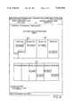
- FIG. 4is a diagram illustrating an exemplary graphical display as received at a remote facsimile machine.
- FIG. 1is a block diagrammatic illustration of a building automation system which includes an event driven graphical facsimile interface exemplifying the present invention.
- the remote reporting systemis centered around a central control system 20 which preferably includes in a host computer 22 which communicates with the remaining elements of the system, processes the programs and maintains the data necessary for remote graphical reporting, and when remote graphical reporting is required, utilizes communication lines 24 to send a graphical message to one or more facsimile receivers 25a-25n.
- the facsimile transmissionis preferably initiated and accomplished via a standard facsimile communication board, available from a number of sources, which can be plugged directly into an expansion slot of a personal computer 22, which serves as the control element for the central control 20.
- the exemplary building automation systemis characterized by a number of digital controllers which are connected together, either in hardwired fashion, or by way of a network, to monitor mechanical and electrical equipment in a building (or a collection of buildings), to report status of the monitored equipment to a central location, and to report alarms to a central location when such alarms occur. Alarms may also be reported to the central location 20 from one or more remote facilities using dial-up telecommunications.
- the primary intent of the typical building automation systemis to reduce costs of maintaining the building, both by reducing staffing costs for maintaining the mechanical equipment in the building, as well as the actual operating costs of the equipment (such as by minimizing energy usage and maximizing fuel efficient operation).
- Successful building automation systemsare those which reduce the overall costs of maintaining and operating the building, along with providing the expected reliability to make it appear to building occupants that the building is being maintained onsite, even though maintenance has been transferred offsite for either all or part of each operating day.
- Building automation systemsare implemented primarily to reduce costs of operating mechanical and electrical equipment needed to control the environment in facilities such as office buildings, school systems, and manufacturing facilities. Building automation systems typically use networks of distributed digital controllers which are responsible for controlling equipment in a specific zone, as well as sharing data with other controllers. These controllers must respond to events such as mechanical breakdown, temperature and humidity changes, and others, by initiating control changes and communicating those conditions, in the form of alarm messages, to a human operator. These alarm messages are used in conjunction with building automation system reports to allow the operator to control the facility in a highly customized, cost-effective manner. Examples of building automation system reports are alarm histories, energy usage and cost histories, trend reports, maintenance time reminders, and others.
- the network 32is preferably implemented as a token passing ring, in order to provide reporting efficiency and speed much higher than has been possible using polling networks.
- the network 32is also extended to the central control 20, such that the processor 22 in the central control 20 is also a member of the local area network.
- the connection between the processor 22 and the global control module 30amay be implemented via other communication modalities, such as dial-up lines, telecommunications, or other data transmission media.
- the global control modulescan be located at different sites in a building, or in different buildings, and are the most general of the control modules adapted to parcel out tasks among a plurality of more specific digital controllers.
- the global control modulesgenerally have a significant amount of programmable functionality such that they are relatively easily customized to the requirements of a particular facility or site (e.g., facilities 31a-31n) in which they are located.
- Global control modules, as well as the more specific control modules to be discussed below,are commercially available elements of the Barber-Colman Network 8000 System.
- the facility 31a associated with global control module 30ais illustrated in FIG. 1, it being appreciated that each of the other global control modules 30b-30n can have the same or a similar facility (31b-31n) associated with it.
- the global controller 30ahas a network 36 emanating therefrom which includes a number of different types of control elements.
- a network 36emanating therefrom which includes a number of different types of control elements.
- the local control modulesalso provide a degree of programmable functionality, but more significantly include a plurality of input/output points for physical connection to monitored equipment.
- the local control modulesare representative of the devices which provide actual monitoring of building equipment for reporting measured real time values for the monitored variables.
- a global control satellite unit 40 and a further global control satellite unit 42are similar to each other except that the unit 42 has the capability of communicating on the power lines whereas the module 40 communicates only on the network. Both are connected to the network and thus can be controlled by the global control module 30a and also can report conditions back to that global control module for passing along the network 32. Both the modules 40 and 42 contain input/output points connected to physical equipment in a similar fashion to the connections of the local control module, and thus are a source of further real time operating data.
- controllers 44, 46Other input/output points are provided by controllers 44, 46.
- the controller 44is intended to be representative of a microzone controller which is a unitary digital controller for a packaged unit, (such as a rooftop heating and cooling system) and has control functions for controlling that unit, as well as sensing functions for monitoring sensors on the unit.
- the controller 46is intended to represent a microflo controller which is representative of the type of units for monitoring and controlling a variable air volume (VAV) unit, and thus would typically control flow controllers as well as actuators for controlling flow equipment such as fans, dampers and local heating coils in a VAV air terminal unit.
- VAVvariable air volume
- control modules 38-46are located in the building (or buildings) to be automated, and thus can be included under a single roof or at widely distributed geographical points.
- the networks 32 interconnecting the global control modules as well as the networks 36 interconnecting a single global control module with its local controllerscan take the form of hardwiring between physically proximate units, telephone lines for dial-up between units, leased lines, and the like. It is not unusual to include many forms of intercommunication in a single building automation system, such that it is difficult to assume that when a given set of data is to be collected it can all be done within a relatively short time since some modes of communication can take longer than others, some are more or less reliable than others, etc.
- a global control module 30might also need to collect information from, and also to poll, various local control modules 38a-38n at distributed sites, and receive reports back from those modules via leased lines in one case or telephone lines in another, before all of the relevant data is assembled.
- all of the relevant datamay be available in one of the global control modules 30a, but still unavailable to the host until it is communicated by the token passing ring 32 which can again be implemented in one or more of the available communication technologies.
- a massive amount of datacan be collected by a building automation system, but assembling relevant elements of that data from remote sites (which may become relevant to each other only upon occurrence of a particular alarm) is not necessarily a trivial task.
- FIG. 2there is shown a breakdown of the elements of an event driven graphical facsimile interface and its association with a building automation system.
- the elements of FIG. 2can be considered at primarily residing in the central control 20, which is typically configured as a unit on the main system network along with the global control modules 30a, 30n. If no major network is utilized, the central control 20 can be associated with the single global control module on the network, communicating to all of the subsidiary local modules arranged in the hierarchy below it.
- the major building related elements of the systemare shown as resident in a building automation system block 50 which is intended to include all of the local modules illustrated in FIG. 1, much of the global control network 30, 32 of that figure, and the many monitored sensors in the building automation system.
- the dashed line closing the bottom of block 50 in FIG. 2is intended to illustrate that the remaining elements illustrated below that block can also be assimilated into the overall building automation system 50. It is for purposes of illustration that they are broken out in FIG. 2.
- the building automation system 50is interfaced to a pair of storage elements 52, 54, the former being adapted to collect and store real time data from the building automation system, and the latter to store fixed data relating to that system. Both are customizable for a particular automation system.
- the fixed data storage 54can typically be thought of as represented by floor plans or other diagrams for the building to be monitored, information relating to the mechanical equipment in the building (such as model numbers and specifications for heaters, chillers and the like), desired formats for periodic reports, dial-up numbers for reporting of alarm conditions, and a myriad of other relevant information which can be customized for a given installation but need not change regularly during the operation of that installation. That information is sometimes referred to as "fixed” herein, in order to distinguish it from the real time data generated by monitoring sensors; the "fixed” data is naturally amenable to change from time to time.
- the real time data collection element 52is intended to represent the ever changing variable data which is monitored by the system and which can serve to drive the automation system controls as the measured variables change. For example, as room temperature gets too high, the building cooling system can be energized to return the room temperature to within desired set points.
- the real time data collection element 52typically contains a relatively large amount of storage for maintaining the current status of the numerous sensing transducers in the system.
- the storage elementsare not necessarily relevant to each other, but selected elements of data relevant to a particular occurrence can be selected under the control of a processor 56 programmed first of all to perform the building automation system functions, and secondly to perform the remote graphical reporting of the present invention.
- processor 56monitors the real time data collected by element 52, compares that data against allowable limits, and operates controlled equipment within the building automation system (not illustrated) to maintain the system within the established setpoints.
- the processor 56is associated with an element 58 which provides the user the opportunity to specify parameters for triggering a report in the first instance and for establishing the content of the report for transmission.
- the element 58will typically include an interactive inquiry software program (operated on the computer 22), and an element of memory programmed to query the user as to the need for and nature of certain reports. The user will answer the queries by inputting information into the processor 56 intended to specify trigger points which will generate a report.
- trigger pointsusually include alarm conditions which are intended to cause the transmission of an alarm report to a remote site, alerting a repairman that attention is needed within a predetermined time frame. Another type of trigger point often utilized is a "time trigger".
- the processor within the systemmaintains a real time clock, and that clock can be utilized to trigger certain events. For example, during the portion of the day when the building is manned, no remote alarms need be generated, but the system can be set to be triggered during the non-manned hours to transmit remote alarms.
- alternate facsimile numberscan be associated with a particular alarm, and a time trigger utilized to establish which of the alternate numbers will be dialed at any given time of day.
- status reportscan be sent at particular times on specified days to predetermined locations, all as triggered by the real time clock within the system.
- transmittable reportswhich can be specified by the user through module 58 include periodic reports such as the aforementioned maintenance reports and the like, intended to be generated at predetermined intervals or after the accumulation of a predetermined number of events in order to provide a desired set of operating conditions to a remote location.
- the user interface 58also provides the means for tailoring each of the reports to the requirements of the building automation system.
- the usercan, for example, specify a particular triggering event, such as a failed chiller unit, and then specify for that particular alarm event the elements of fixed and real time data which are to be reported to the remote location as the alarm report.
- a particular triggering eventsuch as a failed chiller unit
- the usercan specify with that particular alarm that the floor plan for the area served by the chiller is to be transmitted along with the existing temperature in each room on the floor plan, the outside temperature, the air flow and temperature within particular ducts, and other information which the user in his best judgment believes is relevant to the service man who will be dispatched to repair the chiller.
- the graphical informationcan also include catalog information on the chiller, a diagram showing the main repair elements in the particular chiller, and other information tailored in as much detail as thought necessary to achieve maximum effectiveness of the repairman who will be dispatched to the site.
- the processor 56 and user interface 58provide the capability for specifying multiple events for reporting, and a different format or set of data to be transmitted for each of the multiple reports.
- the module 58will thus include in tabular form in memory the following elements of related information for each report or alarm: (1) the triggering condition, (2) the graphical format, (3) the fixed data parameters for the report, (4) the real time operating parameters for the report, (5) the numbers of the facsimile receivers to which the report is to be sent, (6) the priority indication of whether the alarm report is to be transmitted to a remote location, and (7) the class or alarm type (e.g., fire, security, HVAC) of report and specification to which remote location(s) each class of alarm is to be sent.
- the class or alarm typee.g., fire, security, HVAC
- an alarm triggered by activation of a security devicemight be configured to generate a graphical report which includes a floor plan highlighting all of the proximity sensors in the area of the triggered security device, and indicating their current status.
- each of the reportscan be associated with a different receiving station; in the foregoing example, the chiller failure might be reported to a service organization engaged to repair the building equipment, whereas the security alarm might be dispatched to the local police station or security station.
- alarm detection means 60are associated with the processor 56 to monitor the system conditions and compare those system conditions against the user specified (by means of module 58) trigger events.
- the alarm detection module 60signals a graphic assembly module 62 to assemble the fixed and real time data which has been specified for that event, and to format an appropriate report.
- the graphic assembly unit 62has a connection 63 to the fixed data storage element 54 and extracts from the fixed data storage, depending on which of the multiple reports is to be generated, the particular set of fixed data intended for that report.
- that datawill include graphical information, and can also include alphanumeric information intended to give context to the graphical information.
- the graphic assembly module 62also has a circuit connection 64 to the real time data collection element 52 and thus is intended to collect and assemble into the transmittable graphic, the values for the real time data associated with the parameters earlier specified.
- the graphic assembly module 62also has a circuit connection 65 to the processor 56 by which those elements interact to assure that real time values for all of the specified real time parameters have been collected by the module 62 and assembled into the graphic. After all of those elements are assembled, the processor 56 signals the graphic assembly module 62 to initiate a facsimile communication utilizing module 66, which as noted above may be a commercially available facsimile communication card for a personal computer.
- the unit 66is connected via telephone line 67 to the schematically illustrated "remote site" which, as noted above, can be a plurality of sites whose identity is specified by telephone numbers initially specified through use of module 58.
- the module 66dials the number of the assigned facsimile receiver, and upon indication of a connection, transmits the assembled graphical report.
- the importance of the interaction between the graphic assembly module 62 and the processor 56is important in assuring that the graphic which is transmitted to the remote site contains information which is relevant (in the context of time relevance) to the report being made.
- the processor 56has access to the real time data collection module 52 and can assure that all of the data which is inserted into the graphic for the specified real time parameters has been collected within a specified number of seconds or minutes.
- Such a featureis particularly significant when the real time data collected within module 52 can originate from multiple widely distributed geographical sources and can be reported on multiple media. In some cases, it is better to give no value for a particular parameter than to specify a previously stored but out-of-date parameter not recently collected.
- the processorby means of connection 65 continually monitors the graphic being assembled in module 62.
- the processorby means of tables, for example, created within the user specified parameter module 58, knows all of the real time parameters which are to be assembled into the graphic, and can monitor the insertion of each of those parameters so that the processor is aware of the point in time when all of the real time parameters are available, current and inserted in the graphic. It is at that time that the processor 56 will initiate the transmission of the graphic via the module 66, lending the best assurance available that the information transmitted offsite will not be misleading.
- FIG. 3there is shown a system flow diagram illustrating the process performed by the system of FIGS. 1 and 2 in remote reporting of graphical information.
- a block 80which relates to the step of entering user specified parameters, described in hardware terms in connection with element 58 of FIG. 2.
- the userenters the trigger events which specify reports to be transmitted.
- the useralso enters by means of step 80 the format of the reports to be transmitted, including the elements of fixed data, the real time parameters to be transmitted, and any ancillary information to be sent, as well as the telephone numbers of the facsimile machines which are to receive reports.
- Such reportscan include both alarm reports as well as the other reports specified above.
- the user specified information generated in step 80is stored in a step 81 which is identified as a table of transmittable alarm types and elements of graphical display for each type.
- the table 81includes both the trigger events as well as an identification of the elements of the report which are to be transmitted upon detection of the associated trigger.
- the trigger eventscan include not only alarm conditions, but also real time conditions triggered by the real time clock within the system to generate periodic reports or to alter the type of report or report destination dependent upon the time of day at which an alarm occurred.
- system monitoring of building automation system parametersinitiates with a start step 82 followed by a test 83 to detect if an alarm condition has been detected. If no alarm condition has been detected, as in the ordinary course, the process branches at 84 to return to normal processing. However, in the case an alarm has been detected (or a trigger event for a non-alarm report), the process branches at 85 to a further test 86 to determine if the alarm is of the transmittable type. If it is not, the process returns to normal processing at 87. However, if the alarm which has been detected is of the transmittable type, the process branches to a step 88 to determine the alarm type and retrieve the display format.
- the step 88operates in conjunction with the table 81 to determine, from the alarm type, which elements of collected and stored data need to be assembled into the transmittable report.
- a step 89is then performed to assemble the fixed data which usually includes the graphics information. It is recalled that the fixed data is stored within element 54 of the system of FIG. 2.
- a step 90is performed to collect real time data for the real time parameters needed for the report, and to assemble that data into the graphical display.
- a test 92is continually performed to determine whether all of the real time data needed for the report has been collected and entered into the graphic. If it has not, the process continues to repeat the step 90.
- test 92determines that all of the real time data has been collected and entered, following which the process branches to a step 93 to transmit the assembled graphic to one or more remote facsimile stations. While it is not illustrated in FIG. 3, it is possible, of course, upon processing of the loop including steps 90 and 92 for a predetermined period of time, to enter in place of a real time data a default entry such as "none available", and assemble that into the graphic display in place of a real time data point, following which the test 92 will be satisfied so that the report, even though incomplete, will be transmitted.
- the transmit step 93includes, as an important element, the graphic which had been assembled in the prior steps along with the real time data for the specified parameters assembled into the graphic.
- the transmission 93is configured to be accomplished by means of facsimile, such that the transmission is receivable in any intended location by simply installing a relatively inexpensive facsimile machine which then provides a report containing all of the relevant information in context adapted for instantaneous understanding.
- a further step 94to determine that receipt of the transmission is verified.
- a stepis easily performed with commercially available facsimile machines, since the interchange of transmission signals between a sending and receiving machine provides an indication that the transmission has been accurately completed.
- the processbranches to a step 96, which is the completion of the transmission sequence, after which the processor can return to its normal functioning.
- a step 95is performed to engage an alternate report routine.
- the alternate routinecan be programmed to suit a number of requirements. For example, the alternate report routine will typically have a number of levels which are reached in sequence until one of the levels generates a verified transmission.
- the alternate routine 95will first attempt to resend the transmission to the same facsimile number. If that transmission is not verified a second time, the alternate report routine 95 will then cause a search of the table 81 to determine an alternate number for reporting of that particular alarm condition. The re-reporting and alternate reporting will continue until the report is transmitted and the transmission verified.
- the systemmay also generate a further report indicating the inability to verify communication with multiple stations, which itself may be a second type of alarm reported to a different station.
- FIG. 4show a typical graphical report which is transmitted from a central station 20 (FIG. 1) to a selected telefax machine 25a to report fixed information from the building automation system along with currently measured real time operating parameters from that same system.
- FIG. 4has a central portion 100 which illustrates a floor plan for a particular area of a hospital. The portion above the floor plan 100 indicates identification information for the particular floor plan and facility, and the section 104 in the header immediately above section 102 indicates the exact nature of the alarm including the time and date of transmission of the alarm report.
- the header informationincludes the indication "single zone supply fan has failed, dispatch service crew immediately", and that indicates to the service person the type of action needed. It is also seen that on the floor plan 100 there are a series of blocks 110 which indicate the actual room temperature which had been measured in real time just before the time of the report, indicating which areas of the hospital were particularly affected, and the degree to which the system has lost control by virtue of the failure. A further block 112 indicates outside air temperature for further information in determining the urgency of the report. A further page of the report, not illustrated in the drawings, can include a diagram of the mechanical room in which the failed supply fan is located, and highlight the exact location of the supply fan as well as any monitored parameters available directly from that equipment.
- a modification of the illustration of FIG. 4can also highlight the safety aspects of the building automation system. Assuming that the alarm was triggered by a fire rather than a failed supply fan, and the building automation system is configured to transmit a report such as that shown in FIG. 4 in connection with such an alarm, the actual real time temperatures within the specific rooms would be of extreme value to a firefighting team intending to determine how best to approach the fire extinguishing problem. Thus, if data indicated by time to have occurred only minutes earlier indicates that room 405 were say 25° F. hotter than those adjoining it, the firefighters would be advised before they even entered the area of the location of the most intense portion of the fire.
- intelligibilityis enhanced by including graphics in the transmission along with actual real time operating data.
- Credibilityis enhanced by providing a system which assures that the data is current, accurate and assembled, before transmission is allowed.
- Contextis provided by the user in initially configuring the elements to be included in each report, such that the information when transmitted includes all of the data thought relevant to the particular alarm at hand. That extreme amount of relevant information is transmitted to a remote site which need be specialized only to the extent of including a ubiquitous facsimile machine.
Landscapes
- Business, Economics & Management (AREA)
- Emergency Management (AREA)
- Physics & Mathematics (AREA)
- General Physics & Mathematics (AREA)
- Engineering & Computer Science (AREA)
- Signal Processing (AREA)
- Alarm Systems (AREA)
- Selective Calling Equipment (AREA)
Abstract
Description
Claims (15)
Priority Applications (1)
| Application Number | Priority Date | Filing Date | Title |
|---|---|---|---|
| US07/529,945US5061916A (en) | 1990-05-29 | 1990-05-29 | Event driven remote graphical reporting of building automation system parameters |
Applications Claiming Priority (1)
| Application Number | Priority Date | Filing Date | Title |
|---|---|---|---|
| US07/529,945US5061916A (en) | 1990-05-29 | 1990-05-29 | Event driven remote graphical reporting of building automation system parameters |
Publications (1)
| Publication Number | Publication Date |
|---|---|
| US5061916Atrue US5061916A (en) | 1991-10-29 |
Family
ID=24111835
Family Applications (1)
| Application Number | Title | Priority Date | Filing Date |
|---|---|---|---|
| US07/529,945Expired - LifetimeUS5061916A (en) | 1990-05-29 | 1990-05-29 | Event driven remote graphical reporting of building automation system parameters |
Country Status (1)
| Country | Link |
|---|---|
| US (1) | US5061916A (en) |
Cited By (173)
| Publication number | Priority date | Publication date | Assignee | Title |
|---|---|---|---|---|
| WO1992006551A1 (en)* | 1990-10-09 | 1992-04-16 | Autotrol Corporation | Improved apparatus and method for transmitting text data directly to a facsimile machine |
| US5225997A (en)* | 1990-06-05 | 1993-07-06 | Sygnus Controls Inc. | Automatic monitoring and remote reporting device |
| US5276529A (en)* | 1991-01-28 | 1994-01-04 | C & P Of Virginia | System and method for remote testing and protocol analysis of communication lines |
| US5280515A (en)* | 1990-07-10 | 1994-01-18 | Fujitsu Limited | Fault processing system for processing faults of producing points |
| US5297252A (en)* | 1991-05-07 | 1994-03-22 | Don Becker | Color graphics terminal for monitoring an alarm system |
| US5319363A (en)* | 1990-08-31 | 1994-06-07 | The General Hospital Corporation | Network for portable patient monitoring devices |
| US5335339A (en)* | 1990-11-22 | 1994-08-02 | Hitachi, Ltd. | Equipment and method for interactive testing and simulating of a specification of a network system |
| US5353399A (en)* | 1989-11-08 | 1994-10-04 | Hitachi, Ltd. | Method and system for selecting devices in information networks, including inputting/outputting data to a specified device selected by pointing to a corresponding indicator on a screen |
| US5373349A (en)* | 1991-12-10 | 1994-12-13 | Minolta Camera Kabushiki Kaisha | Copying machine control system with communication states with control center being displayed |
| US5375159A (en)* | 1992-09-29 | 1994-12-20 | C & P Of Virginia | System and method for remote testing and protocol analysis of communication lines |
| US5398277A (en)* | 1992-02-06 | 1995-03-14 | Security Information Network, Inc. | Flexible multiprocessor alarm data processing system |
| US5404199A (en)* | 1990-04-10 | 1995-04-04 | Minolta Camera Kabushiki Kaisha | Control apparatus of copying machine with improved communication function for centralized control unit |
| US5408523A (en)* | 1992-06-22 | 1995-04-18 | Basic Measuring Instruments, Inc. | Electronic remote data recorder with facsimile output for utility AC power systems |
| US5412708A (en)* | 1993-03-12 | 1995-05-02 | Katz; Ronald A. | Videophone system for scrutiny monitoring with computer control |
| EP0599131A3 (en)* | 1992-11-20 | 1995-06-28 | Schimmel Gmbh & Co Kg | System for monitoring domestic installations. |
| US5446555A (en)* | 1989-12-28 | 1995-08-29 | Nippon Steel Corporation | Design drawing transmission system |
| US5477338A (en)* | 1992-01-21 | 1995-12-19 | Sharp Kabushiki Kaisha | Facsimile apparatus |
| US5495284A (en)* | 1993-03-12 | 1996-02-27 | Katz; Ronald A. | Scheduling and processing system for telephone video communication |
| US5519878A (en)* | 1992-03-18 | 1996-05-21 | Echelon Corporation | System for installing and configuring (grouping and node address assignment) household devices in an automated environment |
| US5664190A (en)* | 1994-01-21 | 1997-09-02 | International Business Machines Corp. | System and method for enabling an event driven interface to a procedural program |
| US5757892A (en)* | 1995-10-11 | 1998-05-26 | Phonetics, Inc. | Self-contained fax communications appliance |
| GB2320394A (en)* | 1996-11-25 | 1998-06-17 | Irv Kon | Monitoring system |
| US5808902A (en)* | 1996-05-23 | 1998-09-15 | Basic Measuring Instruments | Power quality transducer for use with supervisory control systems |
| US5832066A (en)* | 1994-05-20 | 1998-11-03 | Fujitsu Limited | Audio response/report device |
| US5838776A (en)* | 1996-08-23 | 1998-11-17 | Adkins, Ii; James E. | Power controller for a heating/air conditioning unit |
| WO1999022560A3 (en)* | 1997-11-04 | 1999-08-05 | Nokia Telecommunications Oy | Method for implementing a telephonic service in an isdn network |
| US6041106A (en)* | 1996-07-29 | 2000-03-21 | Elite Entry Phone Corp. | Access control apparatus for use with buildings, gated properties and the like |
| EP0989503A1 (en)* | 1998-09-24 | 2000-03-29 | ULTRA Proizvodnja elektronskih naprav d.o.o. | Network system with remote data acquisition |
| EP0880119A3 (en)* | 1997-05-22 | 2000-05-17 | Telekom Austria Aktiengesellschaft | Remote monitoring system |
| US6147601A (en)* | 1999-01-09 | 2000-11-14 | Heat - Timer Corp. | Electronic message delivery system utilizable in the monitoring of remote equipment and method of same |
| US6160477A (en)* | 1999-01-09 | 2000-12-12 | Heat-Timer Corp. | Electronic message delivery system utilizable in the monitoring of remote equipment and method of same |
| US6211782B1 (en) | 1999-01-09 | 2001-04-03 | Heat-Timer Corporation | Electronic message delivery system utilizable in the monitoring of remote equipment and method of same |
| US6211796B1 (en)* | 1993-12-09 | 2001-04-03 | Steelcase Development Inc. | Communications network for identifying the location of articles relative to a floor plan |
| US6240326B1 (en)* | 1998-04-03 | 2001-05-29 | Johnson Controls Technology Co. | Language independent building automation architecture for worldwide system deployment |
| US6246325B1 (en)* | 1999-11-18 | 2001-06-12 | Agere Systems Guardian Corp. | Distributed communications system for reducing equipment down-time |
| US6252505B1 (en) | 1999-04-06 | 2001-06-26 | Northrop Grumman Corporation | On-site environment monitoring system |
| US20010037334A1 (en)* | 2000-03-02 | 2001-11-01 | Valentine Edmund L. | System and method for creating a book of reports over a computer network |
| US6323894B1 (en) | 1993-03-12 | 2001-11-27 | Telebuyer, Llc | Commercial product routing system with video vending capability |
| US6366893B2 (en) | 1995-11-07 | 2002-04-02 | Nokia Telecommunications Oy | System, a method and an apparatus for performing an electric payment transaction in a telecommunication network |
| US6366889B1 (en)* | 1998-05-18 | 2002-04-02 | Joseph A. Zaloom | Optimizing operational efficiency and reducing costs of major energy system at large facilities |
| US6396597B1 (en)* | 1993-02-10 | 2002-05-28 | Qwest Communications International Inc. | Computer network-based facsimile reception system |
| EP1089493A3 (en)* | 1999-10-01 | 2002-07-03 | General Electric Company | Internet based remote diagnostic system |
| US6437691B1 (en) | 1999-01-09 | 2002-08-20 | Heat-Timer Corporation | Electronic message delivery system utilizable in the monitoring of remote equipment and method of same |
| US6456695B2 (en) | 1998-09-04 | 2002-09-24 | Samsung Electronics, Co., Ltd. | Computer having emergency calling function and emergency calling method using computer |
| US20020174223A1 (en)* | 1999-10-27 | 2002-11-21 | Netbotz Inc. | Method and apparatus for replay of historical oath |
| US6529590B1 (en)* | 1994-11-23 | 2003-03-04 | Coltec Industries, Inc. | Systems and methods for remotely controlling a machine |
| US20030048304A1 (en)* | 2001-07-20 | 2003-03-13 | Lontka Bruce J. | User interface with installment mode |
| US6553336B1 (en) | 1999-06-25 | 2003-04-22 | Telemonitor, Inc. | Smart remote monitoring system and method |
| US20030084216A1 (en)* | 2001-10-26 | 2003-05-01 | Schneider Automation Inc. | Hybrid change of state protocol for CANOpen networks |
| US20030084384A1 (en)* | 2001-10-26 | 2003-05-01 | Schneider Automation Inc. | Residual error handling in a can network |
| GB2381926A (en)* | 2001-10-29 | 2003-05-14 | Chamberlain Group Inc | Access control system comprising fax-modem to transmit alarm condition to a remote location |
| US20030104830A1 (en)* | 2001-12-03 | 2003-06-05 | David Norwood | Method and apparatus for displaying real-time information objects between a wireless mobile user station and multiple information sources based upon event driven parameters and user modifiable object manifest |
| US20040015340A1 (en)* | 2001-09-10 | 2004-01-22 | Hirokazu Kadoi | System for forming power system wiring diagram and power supply apparatus and program for use therein |
| US6701462B1 (en)* | 2000-05-19 | 2004-03-02 | Rockwell Automation Technologies, Inc. | Situational aware output configuration and execution |
| US20040095237A1 (en)* | 1999-01-09 | 2004-05-20 | Chen Kimball C. | Electronic message delivery system utilizable in the monitoring and control of remote equipment and method of same |
| US20040102924A1 (en)* | 2002-11-27 | 2004-05-27 | Jarrell Donald B. | Decision support for operations and maintenance (DSOM) system |
| US20040113768A1 (en)* | 2001-01-17 | 2004-06-17 | Rodgers Stephen Fredrick | Communication system |
| US20040151282A1 (en)* | 2002-05-22 | 2004-08-05 | Jones Russell K. | Condition detection and notification systems and methods |
| US6778945B2 (en) | 2001-12-12 | 2004-08-17 | Battelle Memorial Institute | Rooftop package unit diagnostician |
| US20040160897A1 (en)* | 1999-10-27 | 2004-08-19 | Netbotz, Inc. | Method and system for monitoring computer networks and equipment |
| US20040260427A1 (en)* | 2003-04-08 | 2004-12-23 | William Wimsatt | Home automation contextual user interface |
| US20050131269A1 (en)* | 1995-06-07 | 2005-06-16 | Talmadge Karen D. | System and method for delivering a therapeutic agent for bone disease |
| US20050131267A1 (en)* | 1995-06-07 | 2005-06-16 | Talmadge Karen D. | System and method for delivering a therapeutic agent for bone disease |
| US20050198255A1 (en)* | 2003-12-23 | 2005-09-08 | Johnson Controls Technology Company | Value reporting using web services |
| US7009510B1 (en) | 2002-08-12 | 2006-03-07 | Phonetics, Inc. | Environmental and security monitoring system with flexible alarm notification and status capability |
| US20060064468A1 (en)* | 2004-09-20 | 2006-03-23 | Brown K R | Web services interface and object access framework |
| US7095321B2 (en) | 2003-04-14 | 2006-08-22 | American Power Conversion Corporation | Extensible sensor monitoring, alert processing and notification system and method |
| US7148796B2 (en) | 2003-04-14 | 2006-12-12 | American Power Conversion Corporation | Environmental monitoring device |
| US7159022B2 (en) | 2001-01-26 | 2007-01-02 | American Power Conversion Corporation | Method and system for a set of network appliances which can be connected to provide enhanced collaboration, scalability, and reliability |
| US7206882B2 (en) | 2001-10-26 | 2007-04-17 | Schneider Automation Inc. | Triggered communication network for CANOpen networks |
| US20070203676A1 (en)* | 2006-02-14 | 2007-08-30 | Tadamitsu Jinzenji | Monitor system, and monitor device and data collecting device therefor |
| US20070208437A1 (en)* | 2006-03-01 | 2007-09-06 | Honeywell International Inc. | Characterization of utility demand using utility demand footprint |
| US20070261062A1 (en)* | 2006-04-25 | 2007-11-08 | Emerson Retail Services, Inc. | Building system event manager |
| US20070265821A1 (en)* | 2006-05-12 | 2007-11-15 | Ryo Yokoyama | Simulation apparatus, simulation method, and computer-readable recording medium storing simulation program |
| US20070282478A1 (en)* | 2006-06-05 | 2007-12-06 | Ammar Al-Ali | Parameter upgrade system |
| US20070298772A1 (en)* | 2004-08-27 | 2007-12-27 | Owens Steve B | System and method for an interactive security system for a home |
| US7319477B2 (en) | 1993-03-12 | 2008-01-15 | Telebuyer, Llc | Videophone system for scrutiny monitoring with computer control |
| US7333989B1 (en)* | 1997-03-27 | 2008-02-19 | Hitachi, Ltd. | Method and apparatus for integrating distributed information |
| US20080125887A1 (en)* | 2006-09-27 | 2008-05-29 | Rockwell Automation Technologies, Inc. | Event context data and aggregation for industrial control systems |
| US7392309B2 (en) | 1999-10-27 | 2008-06-24 | American Power Conversion Corporation | Network appliance management |
| US20080185448A1 (en)* | 2007-02-02 | 2008-08-07 | Lg Electronics Inc. | Integrated management system and method using setting information back-up for controlling multi-type air conditioners |
| US20080185447A1 (en)* | 2007-02-02 | 2008-08-07 | Lg Electronics Inc. | Integrated management system and method for controlling multi-type air conditioners |
| US7542963B2 (en) | 2003-04-14 | 2009-06-02 | American Power Conversion Corporation | Method and system for journaling and accessing sensor and configuration data |
| US7627651B2 (en) | 2003-10-27 | 2009-12-01 | American Power Conversion Corporation | System and method for network device communication |
| US7634555B1 (en) | 2003-05-16 | 2009-12-15 | Johnson Controls Technology Company | Building automation system devices |
| US20100011437A1 (en)* | 2008-07-09 | 2010-01-14 | Michael Courtney | Apparatus and method for storing event information for an hvac system |
| US7697927B1 (en) | 2005-01-25 | 2010-04-13 | Embarq Holdings Company, Llc | Multi-campus mobile management system for wirelessly controlling systems of a facility |
| US20100106333A1 (en)* | 2008-10-27 | 2010-04-29 | Lennox Industries Inc. | System and method for zoning a distributed-architecture heating, ventilation and air conditioning network |
| US20100106814A1 (en)* | 2008-10-27 | 2010-04-29 | Lennox Industries Inc. | Device abstraction system and method for a distributed architecture heating, ventilation and air conditioning system |
| US20100102973A1 (en)* | 2008-10-27 | 2010-04-29 | Lennox Industries, Inc. | Alarm and diagnostics system and method for a distributed-architecture heating, ventilation and air conditioning network |
| US20100106330A1 (en)* | 2008-10-27 | 2010-04-29 | Lennox Industries Inc. | Device abstraction system and method for a distributed-architecture heating, ventilation and air conditioning system |
| US20100106329A1 (en)* | 2008-10-27 | 2010-04-29 | Lennox Manufacturing, Inc., A Corporation Of Delaware | Apparatus and method for controlling an environmental conditioning system |
| US20100107111A1 (en)* | 2008-10-27 | 2010-04-29 | Lennox Industries Inc. | System and method of use for a user interface dashboard of a heating, ventilation and air conditioning network |
| US20100106809A1 (en)* | 2008-10-27 | 2010-04-29 | Lennox Industries Inc. | Alarm and diagnostics system and method for a distributed-architecture heating, ventilation and air conditioning network |
| US20100106310A1 (en)* | 2008-10-27 | 2010-04-29 | Lennox Industries Inc. | Alarm and diagnostics system and method for a distributed- architecture heating, ventilation and air conditioning network |
| US20100102948A1 (en)* | 2008-10-27 | 2010-04-29 | Lennox Industries Inc. | Alarm and diagnostics system and method for a distributed architecture heating, ventilation and air conditioning network |
| US20100106305A1 (en)* | 2008-10-24 | 2010-04-29 | Lennox Manufacturing Inc. | Programmable controller and a user interface for same |
| US20100106322A1 (en)* | 2008-10-27 | 2010-04-29 | Lennox Industries Inc. | Communication protocol system and method for a distributed-architecture heating, ventilation and air conditioning network |
| US7711814B1 (en) | 2004-12-13 | 2010-05-04 | American Power Conversion Corporation | Method and system for remote monitoring of a power supply device with user registration capability |
| US20100115364A1 (en)* | 2008-10-27 | 2010-05-06 | Lennox Industries Inc. | Communication protocol system and method for a distributed-architecture heating, ventilation and air conditioning network |
| US20100162110A1 (en)* | 2008-12-22 | 2010-06-24 | Williamson Jon L | Pictorial representations of historical data of building systems |
| US7765573B1 (en) | 2005-03-08 | 2010-07-27 | Embarq Holdings Company, LLP | IP-based scheduling and control of digital video content delivery |
| US7779026B2 (en) | 2002-05-03 | 2010-08-17 | American Power Conversion Corporation | Method and apparatus for collecting and displaying network device information |
| US7840984B1 (en) | 2004-03-17 | 2010-11-23 | Embarq Holdings Company, Llc | Media administering system and method |
| US7840982B1 (en) | 2004-09-28 | 2010-11-23 | Embarq Holding Company, Llc | Video-all call system and method for a facility |
| US20110087650A1 (en)* | 2009-10-06 | 2011-04-14 | Johnson Controls Technology Company | Creation and use of causal relationship models in building management systems and applications |
| US20110088000A1 (en)* | 2009-10-06 | 2011-04-14 | Johnson Controls Technology Company | Systems and methods for displaying a hierarchical set of building management system information |
| US20110137853A1 (en)* | 2009-10-06 | 2011-06-09 | Johnson Controls Technology Company | Systems and methods for reporting a cause of an event or equipment state using causal relationship models in a building management system |
| US7990382B2 (en) | 2006-01-03 | 2011-08-02 | Masimo Corporation | Virtual display |
| US20120011233A1 (en)* | 2010-07-07 | 2012-01-12 | Comcast Interactive Media, Llc | Device Communication, Monitoring and Control Architecture and Method |
| US8145748B2 (en) | 2004-12-13 | 2012-03-27 | American Power Conversion Corporation | Remote monitoring system |
| US8237551B2 (en) | 2008-04-30 | 2012-08-07 | Centurylink Intellectual Property Llc | System and method for in-patient telephony |
| US8271626B2 (en) | 2001-01-26 | 2012-09-18 | American Power Conversion Corporation | Methods for displaying physical network topology and environmental status by location, organization, or responsible party |
| US8274360B2 (en) | 2007-10-12 | 2012-09-25 | Masimo Corporation | Systems and methods for storing, analyzing, and retrieving medical data |
| US8310336B2 (en) | 2008-10-10 | 2012-11-13 | Masimo Corporation | Systems and methods for storing, analyzing, retrieving and displaying streaming medical data |
| US8315364B2 (en) | 1993-03-12 | 2012-11-20 | Telebuyer, Llc | Commercial product telephonic routing system with mobile wireless and video vending capability |
| US20120296451A1 (en)* | 2009-10-21 | 2012-11-22 | Werner Kaps | Building automation and building information system |
| US8433446B2 (en) | 2008-10-27 | 2013-04-30 | Lennox Industries, Inc. | Alarm and diagnostics system and method for a distributed-architecture heating, ventilation and air conditioning network |
| US8437877B2 (en) | 2008-10-27 | 2013-05-07 | Lennox Industries Inc. | System recovery in a heating, ventilation and air conditioning network |
| US20130131840A1 (en)* | 2011-11-11 | 2013-05-23 | Rockwell Automation Technologies, Inc. | Scalable automation system |
| US8452456B2 (en) | 2008-10-27 | 2013-05-28 | Lennox Industries Inc. | System and method of use for a user interface dashboard of a heating, ventilation and air conditioning network |
| US8463442B2 (en) | 2008-10-27 | 2013-06-11 | Lennox Industries, Inc. | Alarm and diagnostics system and method for a distributed architecture heating, ventilation and air conditioning network |
| US8463443B2 (en) | 2008-10-27 | 2013-06-11 | Lennox Industries, Inc. | Memory recovery scheme and data structure in a heating, ventilation and air conditioning network |
| US8516016B2 (en) | 2010-07-07 | 2013-08-20 | Johnson Controls Technology Company | Systems and methods for facilitating communication between a plurality of building automation subsystems |
| US8543243B2 (en) | 2008-10-27 | 2013-09-24 | Lennox Industries, Inc. | System and method of use for a user interface dashboard of a heating, ventilation and air conditioning network |
| US8560125B2 (en) | 2008-10-27 | 2013-10-15 | Lennox Industries | Communication protocol system and method for a distributed-architecture heating, ventilation and air conditioning network |
| US8566292B2 (en) | 2003-04-14 | 2013-10-22 | Schneider Electric It Corporation | Method and system for journaling and accessing sensor and configuration data |
| US8564400B2 (en) | 2008-10-27 | 2013-10-22 | Lennox Industries, Inc. | Communication protocol system and method for a distributed-architecture heating, ventilation and air conditioning network |
| US8571922B2 (en) | 2011-04-21 | 2013-10-29 | Efficiency3 Corp. | Method, technology, and system for displaying, measuring, assessing, and improving the operating and financial performance of metered energy and water consuming systems |
| US8600558B2 (en) | 2008-10-27 | 2013-12-03 | Lennox Industries Inc. | System recovery in a heating, ventilation and air conditioning network |
| US8600559B2 (en) | 2008-10-27 | 2013-12-03 | Lennox Industries Inc. | Method of controlling equipment in a heating, ventilation and air conditioning network |
| US8615326B2 (en) | 2008-10-27 | 2013-12-24 | Lennox Industries Inc. | System and method of use for a user interface dashboard of a heating, ventilation and air conditioning network |
| US8655490B2 (en) | 2008-10-27 | 2014-02-18 | Lennox Industries, Inc. | System and method of use for a user interface dashboard of a heating, ventilation and air conditioning network |
| US8655491B2 (en) | 2008-10-27 | 2014-02-18 | Lennox Industries Inc. | Alarm and diagnostics system and method for a distributed architecture heating, ventilation and air conditioning network |
| US8661165B2 (en) | 2008-10-27 | 2014-02-25 | Lennox Industries, Inc. | Device abstraction system and method for a distributed architecture heating, ventilation and air conditioning system |
| US8682921B2 (en) | 2010-07-07 | 2014-03-25 | Johnson Controls Technology Company | Query engine for building management systems |
| US8694164B2 (en) | 2008-10-27 | 2014-04-08 | Lennox Industries, Inc. | Interactive user guidance interface for a heating, ventilation and air conditioning system |
| US8725298B2 (en) | 2008-10-27 | 2014-05-13 | Lennox Industries, Inc. | Alarm and diagnostics system and method for a distributed architecture heating, ventilation and conditioning network |
| US8744629B2 (en) | 2008-10-27 | 2014-06-03 | Lennox Industries Inc. | System and method of use for a user interface dashboard of a heating, ventilation and air conditioning network |
| US8762666B2 (en) | 2008-10-27 | 2014-06-24 | Lennox Industries, Inc. | Backup and restoration of operation control data in a heating, ventilation and air conditioning network |
| US8761945B2 (en) | 2008-10-27 | 2014-06-24 | Lennox Industries Inc. | Device commissioning in a heating, ventilation and air conditioning network |
| US8798796B2 (en) | 2008-10-27 | 2014-08-05 | Lennox Industries Inc. | General control techniques in a heating, ventilation and air conditioning network |
| US8802981B2 (en) | 2008-10-27 | 2014-08-12 | Lennox Industries Inc. | Flush wall mount thermostat and in-set mounting plate for a heating, ventilation and air conditioning system |
| US20140266671A1 (en)* | 2013-03-12 | 2014-09-18 | Honeywell International Inc. | Mechanism and approach for monitoring building automation systems through user defined content notifications |
| US8874815B2 (en) | 2008-10-27 | 2014-10-28 | Lennox Industries, Inc. | Communication protocol system and method for a distributed architecture heating, ventilation and air conditioning network |
| US8892797B2 (en) | 2008-10-27 | 2014-11-18 | Lennox Industries Inc. | Communication protocol system and method for a distributed-architecture heating, ventilation and air conditioning network |
| US8920317B2 (en) | 2003-07-25 | 2014-12-30 | Masimo Corporation | Multipurpose sensor port |
| US8977794B2 (en) | 2008-10-27 | 2015-03-10 | Lennox Industries, Inc. | Communication protocol system and method for a distributed-architecture heating, ventilation and air conditioning network |
| US8990536B2 (en) | 2011-06-01 | 2015-03-24 | Schneider Electric It Corporation | Systems and methods for journaling and executing device control instructions |
| US9075136B1 (en) | 1998-03-04 | 2015-07-07 | Gtj Ventures, Llc | Vehicle operator and/or occupant information apparatus and method |
| US9142118B2 (en) | 2007-08-03 | 2015-09-22 | Belkin International, Inc. | Emergency notification device and system |
| US9218454B2 (en) | 2009-03-04 | 2015-12-22 | Masimo Corporation | Medical monitoring system |
| US9225944B2 (en) | 2011-09-08 | 2015-12-29 | Schneider Electric It Corporation | Method and system for displaying a coverage area of a camera in a data center |
| US9268345B2 (en) | 2008-10-27 | 2016-02-23 | Lennox Industries Inc. | System and method of use for a user interface dashboard of a heating, ventilation and air conditioning network |
| US9323894B2 (en) | 2011-08-19 | 2016-04-26 | Masimo Corporation | Health care sanitation monitoring system |
| US9325517B2 (en) | 2008-10-27 | 2016-04-26 | Lennox Industries Inc. | Device abstraction system and method for a distributed-architecture heating, ventilation and air conditioning system |
| US9632490B2 (en) | 2008-10-27 | 2017-04-25 | Lennox Industries Inc. | System and method for zoning a distributed architecture heating, ventilation and air conditioning network |
| US9651925B2 (en) | 2008-10-27 | 2017-05-16 | Lennox Industries Inc. | System and method for zoning a distributed-architecture heating, ventilation and air conditioning network |
| US9678486B2 (en) | 2008-10-27 | 2017-06-13 | Lennox Industries Inc. | Device abstraction system and method for a distributed-architecture heating, ventilation and air conditioning system |
| US9795739B2 (en) | 2009-05-20 | 2017-10-24 | Masimo Corporation | Hemoglobin display and patient treatment |
| US9952103B2 (en) | 2011-12-22 | 2018-04-24 | Schneider Electric It Corporation | Analysis of effect of transient events on temperature in a data center |
| US10007758B2 (en) | 2009-03-04 | 2018-06-26 | Masimo Corporation | Medical monitoring system |
| US10032002B2 (en) | 2009-03-04 | 2018-07-24 | Masimo Corporation | Medical monitoring system |
| US10152876B2 (en) | 1996-03-27 | 2018-12-11 | Gtj Ventures, Llc | Control, monitoring, and/or security apparatus and method |
| US10190792B2 (en) | 2016-04-27 | 2019-01-29 | Crestron Electronics, Inc. | Three-dimensional building management system visualization |
| US10546441B2 (en) | 2013-06-04 | 2020-01-28 | Raymond Anthony Joao | Control, monitoring, and/or security, apparatus and method for premises, vehicles, and/or articles |
| US10562492B2 (en) | 2002-05-01 | 2020-02-18 | Gtj Ventures, Llc | Control, monitoring and/or security apparatus and method |
| US10796268B2 (en) | 2001-01-23 | 2020-10-06 | Gtj Ventures, Llc | Apparatus and method for providing shipment information |
| US11076507B2 (en) | 2007-05-15 | 2021-07-27 | Schneider Electric It Corporation | Methods and systems for managing facility power and cooling |
| US11317837B2 (en) | 2006-10-12 | 2022-05-03 | Masimo Corporation | System and method for monitoring the life of a physiological sensor |
| US11798387B2 (en) | 2021-04-15 | 2023-10-24 | Honeywell International Inc. | Determination and notification of a location of a building safety system event |
| US20240259229A1 (en)* | 2010-12-20 | 2024-08-01 | Icontrol Networks, Inc. | Defining and implementing sensor triggered response rules |
| US12394301B2 (en) | 2021-04-15 | 2025-08-19 | Honeywell International Inc. | Live status notification of response personnel actions to building owner/operators |
Citations (4)
| Publication number | Priority date | Publication date | Assignee | Title |
|---|---|---|---|---|
| US4644478A (en)* | 1983-09-13 | 1987-02-17 | International Business Machines Corp. | Monitoring and alarm system for custom applications |
| US4933667A (en)* | 1988-09-23 | 1990-06-12 | Fike Corporation | Graphic annunciator |
| US4977390A (en)* | 1989-10-19 | 1990-12-11 | Niagara Mohawk Power Corporation | Real time method for processing alaarms generated within a predetermined system |
| US4991200A (en)* | 1987-09-29 | 1991-02-05 | Paul Lin | Interface device for the intercommunication of a computer and a fax machine |
- 1990
- 1990-05-29USUS07/529,945patent/US5061916A/ennot_activeExpired - Lifetime
Patent Citations (4)
| Publication number | Priority date | Publication date | Assignee | Title |
|---|---|---|---|---|
| US4644478A (en)* | 1983-09-13 | 1987-02-17 | International Business Machines Corp. | Monitoring and alarm system for custom applications |
| US4991200A (en)* | 1987-09-29 | 1991-02-05 | Paul Lin | Interface device for the intercommunication of a computer and a fax machine |
| US4933667A (en)* | 1988-09-23 | 1990-06-12 | Fike Corporation | Graphic annunciator |
| US4977390A (en)* | 1989-10-19 | 1990-12-11 | Niagara Mohawk Power Corporation | Real time method for processing alaarms generated within a predetermined system |
Non-Patent Citations (6)
| Title |
|---|
| "New Controls Gear Highlights Atlanta HVAC Exposition", Energy User News, Feb. 1990. |
| Brochure entitled "Network 8000 System Overview", May 1989. |
| Brochure entitled Network 8000 System Overview , May 1989.* |
| Data Sheet on the Quadram JT FAX9600.* |
| Data Sheet on the Quadram JT-FAX9600. |
| New Controls Gear Highlights Atlanta HVAC Exposition , Energy User News, Feb. 1990.* |
Cited By (277)
| Publication number | Priority date | Publication date | Assignee | Title |
|---|---|---|---|---|
| US5353399A (en)* | 1989-11-08 | 1994-10-04 | Hitachi, Ltd. | Method and system for selecting devices in information networks, including inputting/outputting data to a specified device selected by pointing to a corresponding indicator on a screen |
| US5446555A (en)* | 1989-12-28 | 1995-08-29 | Nippon Steel Corporation | Design drawing transmission system |
| US5404199A (en)* | 1990-04-10 | 1995-04-04 | Minolta Camera Kabushiki Kaisha | Control apparatus of copying machine with improved communication function for centralized control unit |
| US5225997A (en)* | 1990-06-05 | 1993-07-06 | Sygnus Controls Inc. | Automatic monitoring and remote reporting device |
| US5280515A (en)* | 1990-07-10 | 1994-01-18 | Fujitsu Limited | Fault processing system for processing faults of producing points |
| US5319363A (en)* | 1990-08-31 | 1994-06-07 | The General Hospital Corporation | Network for portable patient monitoring devices |
| WO1992006551A1 (en)* | 1990-10-09 | 1992-04-16 | Autotrol Corporation | Improved apparatus and method for transmitting text data directly to a facsimile machine |
| US5335267A (en)* | 1990-10-09 | 1994-08-02 | Autotrol Corporation | Apparatus and method for transmitting text data directly to a facsimile machine |
| US5335339A (en)* | 1990-11-22 | 1994-08-02 | Hitachi, Ltd. | Equipment and method for interactive testing and simulating of a specification of a network system |
| US5276529A (en)* | 1991-01-28 | 1994-01-04 | C & P Of Virginia | System and method for remote testing and protocol analysis of communication lines |
| US5297252A (en)* | 1991-05-07 | 1994-03-22 | Don Becker | Color graphics terminal for monitoring an alarm system |
| US5373349A (en)* | 1991-12-10 | 1994-12-13 | Minolta Camera Kabushiki Kaisha | Copying machine control system with communication states with control center being displayed |
| US5477338A (en)* | 1992-01-21 | 1995-12-19 | Sharp Kabushiki Kaisha | Facsimile apparatus |
| US5398277A (en)* | 1992-02-06 | 1995-03-14 | Security Information Network, Inc. | Flexible multiprocessor alarm data processing system |
| US5519878A (en)* | 1992-03-18 | 1996-05-21 | Echelon Corporation | System for installing and configuring (grouping and node address assignment) household devices in an automated environment |
| US5408523A (en)* | 1992-06-22 | 1995-04-18 | Basic Measuring Instruments, Inc. | Electronic remote data recorder with facsimile output for utility AC power systems |
| US5375159A (en)* | 1992-09-29 | 1994-12-20 | C & P Of Virginia | System and method for remote testing and protocol analysis of communication lines |
| EP0599131A3 (en)* | 1992-11-20 | 1995-06-28 | Schimmel Gmbh & Co Kg | System for monitoring domestic installations. |
| US6452691B1 (en) | 1993-02-10 | 2002-09-17 | Qwest Communications International Inc. | Computer network-based facsimile reception system |
| US6396597B1 (en)* | 1993-02-10 | 2002-05-28 | Qwest Communications International Inc. | Computer network-based facsimile reception system |
| US6323894B1 (en) | 1993-03-12 | 2001-11-27 | Telebuyer, Llc | Commercial product routing system with video vending capability |
| US5495284A (en)* | 1993-03-12 | 1996-02-27 | Katz; Ronald A. | Scheduling and processing system for telephone video communication |
| US7839984B2 (en) | 1993-03-12 | 2010-11-23 | Telebuyer, Llc | Commercial product routing system with video vending capability |
| US7835509B2 (en) | 1993-03-12 | 2010-11-16 | Telebuyer, Llc | Commercial product routing system with video vending capability |
| US7425978B2 (en) | 1993-03-12 | 2008-09-16 | Telebuyer, Llc | Videophone system for scrutiny monitoring with computer control |
| US7835508B1 (en) | 1993-03-12 | 2010-11-16 | Telebuyer, Llc | Commercial product routing system with video vending capability |
| US5412708A (en)* | 1993-03-12 | 1995-05-02 | Katz; Ronald A. | Videophone system for scrutiny monitoring with computer control |
| US8111279B2 (en) | 1993-03-12 | 2012-02-07 | Telebuyer Llc | Commercial product routing system with video vending capability |
| US8098272B2 (en) | 1993-03-12 | 2012-01-17 | Telebuyer, Llc | Commercial product routing system with video vending capability |
| US7848496B2 (en) | 1993-03-12 | 2010-12-07 | Telebuyer, Llc | Method for buyer-seller-on-line commerce |
| US8207998B1 (en) | 1993-03-12 | 2012-06-26 | Telebuyer, Llc | Commercial product routing system with video vending capability |
| US8059796B2 (en) | 1993-03-12 | 2011-11-15 | Telebuyer, Llc | Commercial product routing system with video vending capability |
| US8315364B2 (en) | 1993-03-12 | 2012-11-20 | Telebuyer, Llc | Commercial product telephonic routing system with mobile wireless and video vending capability |
| US7319477B2 (en) | 1993-03-12 | 2008-01-15 | Telebuyer, Llc | Videophone system for scrutiny monitoring with computer control |
| US9053485B2 (en) | 1993-03-12 | 2015-06-09 | Telebuyer, Llc | Security monitoring system with image comparison of monitored location |
| US8842151B2 (en) | 1993-03-12 | 2014-09-23 | Telebuyer, Llc | Security monitoring system with flexible monitoring sequence |
| US8836749B2 (en) | 1993-03-12 | 2014-09-16 | Telebuyer, Llc | Security monitoring system with combined video and graphics display |
| US6211796B1 (en)* | 1993-12-09 | 2001-04-03 | Steelcase Development Inc. | Communications network for identifying the location of articles relative to a floor plan |
| US5664190A (en)* | 1994-01-21 | 1997-09-02 | International Business Machines Corp. | System and method for enabling an event driven interface to a procedural program |
| US5832066A (en)* | 1994-05-20 | 1998-11-03 | Fujitsu Limited | Audio response/report device |
| US6529590B1 (en)* | 1994-11-23 | 2003-03-04 | Coltec Industries, Inc. | Systems and methods for remotely controlling a machine |
| US20050131267A1 (en)* | 1995-06-07 | 2005-06-16 | Talmadge Karen D. | System and method for delivering a therapeutic agent for bone disease |
| US20050131269A1 (en)* | 1995-06-07 | 2005-06-16 | Talmadge Karen D. | System and method for delivering a therapeutic agent for bone disease |
| US5757892A (en)* | 1995-10-11 | 1998-05-26 | Phonetics, Inc. | Self-contained fax communications appliance |
| US6366893B2 (en) | 1995-11-07 | 2002-04-02 | Nokia Telecommunications Oy | System, a method and an apparatus for performing an electric payment transaction in a telecommunication network |
| US10152876B2 (en) | 1996-03-27 | 2018-12-11 | Gtj Ventures, Llc | Control, monitoring, and/or security apparatus and method |
| US5808902A (en)* | 1996-05-23 | 1998-09-15 | Basic Measuring Instruments | Power quality transducer for use with supervisory control systems |
| US6041106A (en)* | 1996-07-29 | 2000-03-21 | Elite Entry Phone Corp. | Access control apparatus for use with buildings, gated properties and the like |
| US5838776A (en)* | 1996-08-23 | 1998-11-17 | Adkins, Ii; James E. | Power controller for a heating/air conditioning unit |
| GB2320394A (en)* | 1996-11-25 | 1998-06-17 | Irv Kon | Monitoring system |
| US7333989B1 (en)* | 1997-03-27 | 2008-02-19 | Hitachi, Ltd. | Method and apparatus for integrating distributed information |
| EP0880119A3 (en)* | 1997-05-22 | 2000-05-17 | Telekom Austria Aktiengesellschaft | Remote monitoring system |
| WO1999022560A3 (en)* | 1997-11-04 | 1999-08-05 | Nokia Telecommunications Oy | Method for implementing a telephonic service in an isdn network |
| US9075136B1 (en) | 1998-03-04 | 2015-07-07 | Gtj Ventures, Llc | Vehicle operator and/or occupant information apparatus and method |
| US6240326B1 (en)* | 1998-04-03 | 2001-05-29 | Johnson Controls Technology Co. | Language independent building automation architecture for worldwide system deployment |
| US6366889B1 (en)* | 1998-05-18 | 2002-04-02 | Joseph A. Zaloom | Optimizing operational efficiency and reducing costs of major energy system at large facilities |
| US6456695B2 (en) | 1998-09-04 | 2002-09-24 | Samsung Electronics, Co., Ltd. | Computer having emergency calling function and emergency calling method using computer |
| EP0989503A1 (en)* | 1998-09-24 | 2000-03-29 | ULTRA Proizvodnja elektronskih naprav d.o.o. | Network system with remote data acquisition |
| WO2000018175A3 (en)* | 1998-09-24 | 2000-05-25 | Ultra | Network system with remote data acquisition |
| US6211782B1 (en) | 1999-01-09 | 2001-04-03 | Heat-Timer Corporation | Electronic message delivery system utilizable in the monitoring of remote equipment and method of same |
| US6462654B1 (en)* | 1999-01-09 | 2002-10-08 | Heat-Timer Corporation | Electronic message delivery system utilizable in the monitoring of remote equipment and method of same |
| US6147601A (en)* | 1999-01-09 | 2000-11-14 | Heat - Timer Corp. | Electronic message delivery system utilizable in the monitoring of remote equipment and method of same |
| US6160477A (en)* | 1999-01-09 | 2000-12-12 | Heat-Timer Corp. | Electronic message delivery system utilizable in the monitoring of remote equipment and method of same |
| US20040095237A1 (en)* | 1999-01-09 | 2004-05-20 | Chen Kimball C. | Electronic message delivery system utilizable in the monitoring and control of remote equipment and method of same |
| US6437691B1 (en) | 1999-01-09 | 2002-08-20 | Heat-Timer Corporation | Electronic message delivery system utilizable in the monitoring of remote equipment and method of same |
| US6535123B2 (en)* | 1999-01-09 | 2003-03-18 | Heat - Timer Corporation | Electronic message delivery system |
| US6717513B1 (en)* | 1999-01-09 | 2004-04-06 | Heat-Timer Corporation | Electronic message delivery system utilizable in the monitoring of remote equipment and method of same |
| US6252505B1 (en) | 1999-04-06 | 2001-06-26 | Northrop Grumman Corporation | On-site environment monitoring system |
| US6553336B1 (en) | 1999-06-25 | 2003-04-22 | Telemonitor, Inc. | Smart remote monitoring system and method |
| EP1089493A3 (en)* | 1999-10-01 | 2002-07-03 | General Electric Company | Internet based remote diagnostic system |
| US20070088823A1 (en)* | 1999-10-27 | 2007-04-19 | Fowler John J | Method and System for Monitoring Computer Networks and Equipment |
| US8005944B2 (en) | 1999-10-27 | 2011-08-23 | American Power Conversion Corporation | Method and system for monitoring computer networks and equipment |
| US8024451B2 (en) | 1999-10-27 | 2011-09-20 | American Power Conversion Corporation | Method and system for monitoring computer networks and equipment |
| US8224953B2 (en) | 1999-10-27 | 2012-07-17 | American Power Conversion Corporation | Method and apparatus for replay of historical data |
| US7330886B2 (en) | 1999-10-27 | 2008-02-12 | American Power Conversion Corporation | Network appliance management |
| US7392309B2 (en) | 1999-10-27 | 2008-06-24 | American Power Conversion Corporation | Network appliance management |
| US20040160897A1 (en)* | 1999-10-27 | 2004-08-19 | Netbotz, Inc. | Method and system for monitoring computer networks and equipment |
| US20020174223A1 (en)* | 1999-10-27 | 2002-11-21 | Netbotz Inc. | Method and apparatus for replay of historical oath |
| US8090817B2 (en) | 1999-10-27 | 2012-01-03 | American Power Conversion Corporation | Method and system for monitoring computer networks and equipment |
| US20090064046A1 (en)* | 1999-10-27 | 2009-03-05 | American Power Conversion Corporation | Method and apparatus for replay of historical data |
| US6246325B1 (en)* | 1999-11-18 | 2001-06-12 | Agere Systems Guardian Corp. | Distributed communications system for reducing equipment down-time |
| US7315864B2 (en)* | 2000-03-02 | 2008-01-01 | Valentine Edmund L | System and method for creating a book of reports over a computer network |
| US20010037334A1 (en)* | 2000-03-02 | 2001-11-01 | Valentine Edmund L. | System and method for creating a book of reports over a computer network |
| US6701462B1 (en)* | 2000-05-19 | 2004-03-02 | Rockwell Automation Technologies, Inc. | Situational aware output configuration and execution |
| US20040113768A1 (en)* | 2001-01-17 | 2004-06-17 | Rodgers Stephen Fredrick | Communication system |
| US10796268B2 (en) | 2001-01-23 | 2020-10-06 | Gtj Ventures, Llc | Apparatus and method for providing shipment information |
| US7159022B2 (en) | 2001-01-26 | 2007-01-02 | American Power Conversion Corporation | Method and system for a set of network appliances which can be connected to provide enhanced collaboration, scalability, and reliability |
| US8271626B2 (en) | 2001-01-26 | 2012-09-18 | American Power Conversion Corporation | Methods for displaying physical network topology and environmental status by location, organization, or responsible party |
| US8966044B2 (en) | 2001-01-26 | 2015-02-24 | Schneider Electric It Corporation | Methods for displaying physical network topology and environmental status by location, organization, or responsible party |
| US7529838B2 (en) | 2001-01-26 | 2009-05-05 | American Power Conversion Corporation | Method and system for a set of network appliances which can be connected to provide enhanced collaboration, scalability, and reliability |
| US7380210B2 (en)* | 2001-07-20 | 2008-05-27 | Siemens Building Technologies, Inc. | User interface with installment mode |
| US20030048304A1 (en)* | 2001-07-20 | 2003-03-13 | Lontka Bruce J. | User interface with installment mode |
| US7444208B2 (en)* | 2001-09-10 | 2008-10-28 | Densei-Lambda K.K. | Electrical system wiring diagram generating system, and power supply device and program used for the same |
| US20040015340A1 (en)* | 2001-09-10 | 2004-01-22 | Hirokazu Kadoi | System for forming power system wiring diagram and power supply apparatus and program for use therein |
| US20030084384A1 (en)* | 2001-10-26 | 2003-05-01 | Schneider Automation Inc. | Residual error handling in a can network |
| US6907485B2 (en) | 2001-10-26 | 2005-06-14 | Schneider Automation Inc. | Hybrid change of state protocol for CANOpen networks |
| US20030084216A1 (en)* | 2001-10-26 | 2003-05-01 | Schneider Automation Inc. | Hybrid change of state protocol for CANOpen networks |
| US7206882B2 (en) | 2001-10-26 | 2007-04-17 | Schneider Automation Inc. | Triggered communication network for CANOpen networks |
| US6748061B2 (en) | 2001-10-29 | 2004-06-08 | The Chamberlain Group, Inc. | Access control system having a programmable automatic notification feature |
| GB2381926A (en)* | 2001-10-29 | 2003-05-14 | Chamberlain Group Inc | Access control system comprising fax-modem to transmit alarm condition to a remote location |
| US7289793B2 (en)* | 2001-12-03 | 2007-10-30 | Scott Gilbert | Method and apparatus for displaying real-time information objects between a wireless mobile user station and multiple information sources based upon event driven parameters and user modifiable object manifest |
| US20030104830A1 (en)* | 2001-12-03 | 2003-06-05 | David Norwood | Method and apparatus for displaying real-time information objects between a wireless mobile user station and multiple information sources based upon event driven parameters and user modifiable object manifest |
| US6778945B2 (en) | 2001-12-12 | 2004-08-17 | Battelle Memorial Institute | Rooftop package unit diagnostician |
| US10562492B2 (en) | 2002-05-01 | 2020-02-18 | Gtj Ventures, Llc | Control, monitoring and/or security apparatus and method |
| US20110040781A1 (en)* | 2002-05-03 | 2011-02-17 | American Power Conversion Corporation | Method and apparatus for collecting and displaying network device information |
| US7958170B2 (en) | 2002-05-03 | 2011-06-07 | American Power Conversion Corporation | Method and apparatus for collecting and displaying data associated with network devices |
| US8019798B2 (en) | 2002-05-03 | 2011-09-13 | American Power Conversion Corporation | Method and apparatus for collecting and displaying network device information |
| US8719319B2 (en) | 2002-05-03 | 2014-05-06 | Schneider Electric It Corporation | Method and apparatus for collecting and displaying network device information |
| US7779026B2 (en) | 2002-05-03 | 2010-08-17 | American Power Conversion Corporation | Method and apparatus for collecting and displaying network device information |
| US6850601B2 (en) | 2002-05-22 | 2005-02-01 | Sentinel Vision, Inc. | Condition detection and notification systems and methods |
| US20040151282A1 (en)* | 2002-05-22 | 2004-08-05 | Jones Russell K. | Condition detection and notification systems and methods |
| US7009510B1 (en) | 2002-08-12 | 2006-03-07 | Phonetics, Inc. | Environmental and security monitoring system with flexible alarm notification and status capability |
| US20040102924A1 (en)* | 2002-11-27 | 2004-05-27 | Jarrell Donald B. | Decision support for operations and maintenance (DSOM) system |
| US7016742B2 (en) | 2002-11-27 | 2006-03-21 | Bahelle Memorial Institute | Decision support for operations and maintenance (DSOM) system |
| WO2004051911A3 (en)* | 2002-12-03 | 2004-11-11 | Scott Gilbert | Displaying real-time information objects between mobile station and multiple information sources based upon event driven parameters |
| US7047092B2 (en)* | 2003-04-08 | 2006-05-16 | Coraccess Systems | Home automation contextual user interface |
| US20040260427A1 (en)* | 2003-04-08 | 2004-12-23 | William Wimsatt | Home automation contextual user interface |
| US7456733B2 (en) | 2003-04-14 | 2008-11-25 | American Power Conversion Corporation | Environmental monitoring device |
| US20090195379A1 (en)* | 2003-04-14 | 2009-08-06 | American Power Conversion Corporation | Environmental monitoring device |
| US7986224B2 (en) | 2003-04-14 | 2011-07-26 | American Power Conversion Corporation | Environmental monitoring device |
| US7456736B2 (en) | 2003-04-14 | 2008-11-25 | American Power Conversion Corporation | Extensible sensor monitoring, alert processing and notification system and method |
| US7542963B2 (en) | 2003-04-14 | 2009-06-02 | American Power Conversion Corporation | Method and system for journaling and accessing sensor and configuration data |
| US7095321B2 (en) | 2003-04-14 | 2006-08-22 | American Power Conversion Corporation | Extensible sensor monitoring, alert processing and notification system and method |
| US8566292B2 (en) | 2003-04-14 | 2013-10-22 | Schneider Electric It Corporation | Method and system for journaling and accessing sensor and configuration data |
| US7148796B2 (en) | 2003-04-14 | 2006-12-12 | American Power Conversion Corporation | Environmental monitoring device |
| US8190728B1 (en) | 2003-05-16 | 2012-05-29 | Johnson Controls Technology Company | Building automation system devices |
| US7634555B1 (en) | 2003-05-16 | 2009-12-15 | Johnson Controls Technology Company | Building automation system devices |
| US8920317B2 (en) | 2003-07-25 | 2014-12-30 | Masimo Corporation | Multipurpose sensor port |
| US10058275B2 (en) | 2003-07-25 | 2018-08-28 | Masimo Corporation | Multipurpose sensor port |
| US11020029B2 (en) | 2003-07-25 | 2021-06-01 | Masimo Corporation | Multipurpose sensor port |
| US8015255B2 (en) | 2003-10-27 | 2011-09-06 | American Power Conversion Corporation | System and method for network device communication |
| US20100138505A1 (en)* | 2003-10-27 | 2010-06-03 | American Power Conversion Corporation | System and method for network device communication |
| US7627651B2 (en) | 2003-10-27 | 2009-12-01 | American Power Conversion Corporation | System and method for network device communication |
| US20050198255A1 (en)* | 2003-12-23 | 2005-09-08 | Johnson Controls Technology Company | Value reporting using web services |
| US7840984B1 (en) | 2004-03-17 | 2010-11-23 | Embarq Holdings Company, Llc | Media administering system and method |
| US7786891B2 (en) | 2004-08-27 | 2010-08-31 | Embarq Holdings Company, Llc | System and method for an interactive security system for a home |
| US20070298772A1 (en)* | 2004-08-27 | 2007-12-27 | Owens Steve B | System and method for an interactive security system for a home |
| US20060064468A1 (en)* | 2004-09-20 | 2006-03-23 | Brown K R | Web services interface and object access framework |
| US7840982B1 (en) | 2004-09-28 | 2010-11-23 | Embarq Holding Company, Llc | Video-all call system and method for a facility |
| US7711814B1 (en) | 2004-12-13 | 2010-05-04 | American Power Conversion Corporation | Method and system for remote monitoring of a power supply device with user registration capability |
| US9166870B2 (en) | 2004-12-13 | 2015-10-20 | Schneider Electric It Corporation | Remote monitoring system |
| US8145748B2 (en) | 2004-12-13 | 2012-03-27 | American Power Conversion Corporation | Remote monitoring system |
| US7697927B1 (en) | 2005-01-25 | 2010-04-13 | Embarq Holdings Company, Llc | Multi-campus mobile management system for wirelessly controlling systems of a facility |
| US7765573B1 (en) | 2005-03-08 | 2010-07-27 | Embarq Holdings Company, LLP | IP-based scheduling and control of digital video content delivery |
| US7990382B2 (en) | 2006-01-03 | 2011-08-02 | Masimo Corporation | Virtual display |
| US7505875B2 (en)* | 2006-02-14 | 2009-03-17 | Omron Corporation | Monitor system, and monitor device and data collecting device therefor |
| US20070203676A1 (en)* | 2006-02-14 | 2007-08-30 | Tadamitsu Jinzenji | Monitor system, and monitor device and data collecting device therefor |
| US20070208437A1 (en)* | 2006-03-01 | 2007-09-06 | Honeywell International Inc. | Characterization of utility demand using utility demand footprint |
| US7392115B2 (en)* | 2006-03-01 | 2008-06-24 | Honeywell International Inc. | Characterization of utility demand using utility demand footprint |
| US20070261062A1 (en)* | 2006-04-25 | 2007-11-08 | Emerson Retail Services, Inc. | Building system event manager |
| US20070265821A1 (en)* | 2006-05-12 | 2007-11-15 | Ryo Yokoyama | Simulation apparatus, simulation method, and computer-readable recording medium storing simulation program |
| US10188348B2 (en) | 2006-06-05 | 2019-01-29 | Masimo Corporation | Parameter upgrade system |
| US12109048B2 (en) | 2006-06-05 | 2024-10-08 | Masimo Corporation | Parameter upgrade system |
| US20070282478A1 (en)* | 2006-06-05 | 2007-12-06 | Ammar Al-Ali | Parameter upgrade system |
| US11191485B2 (en) | 2006-06-05 | 2021-12-07 | Masimo Corporation | Parameter upgrade system |
| US20080125887A1 (en)* | 2006-09-27 | 2008-05-29 | Rockwell Automation Technologies, Inc. | Event context data and aggregation for industrial control systems |
| US11317837B2 (en) | 2006-10-12 | 2022-05-03 | Masimo Corporation | System and method for monitoring the life of a physiological sensor |
| US11857319B2 (en) | 2006-10-12 | 2024-01-02 | Masimo Corporation | System and method for monitoring the life of a physiological sensor |
| US12127835B2 (en) | 2006-10-12 | 2024-10-29 | Masimo Corporation | System and method for monitoring the life of a physiological sensor |
| US7974740B2 (en) | 2007-02-02 | 2011-07-05 | Lg Electronics Inc. | Integrated management system and method using setting information back-up for controlling multi-type air conditioners |
| US7831339B2 (en)* | 2007-02-02 | 2010-11-09 | Lg Electronics Inc. | Integrated management system and method for controlling multi-type air conditioners |
| US20080185447A1 (en)* | 2007-02-02 | 2008-08-07 | Lg Electronics Inc. | Integrated management system and method for controlling multi-type air conditioners |
| US20080185448A1 (en)* | 2007-02-02 | 2008-08-07 | Lg Electronics Inc. | Integrated management system and method using setting information back-up for controlling multi-type air conditioners |
| US11503744B2 (en) | 2007-05-15 | 2022-11-15 | Schneider Electric It Corporation | Methods and systems for managing facility power and cooling |
| US11076507B2 (en) | 2007-05-15 | 2021-07-27 | Schneider Electric It Corporation | Methods and systems for managing facility power and cooling |
| US9142118B2 (en) | 2007-08-03 | 2015-09-22 | Belkin International, Inc. | Emergency notification device and system |
| US9142117B2 (en) | 2007-10-12 | 2015-09-22 | Masimo Corporation | Systems and methods for storing, analyzing, retrieving and displaying streaming medical data |
| US8274360B2 (en) | 2007-10-12 | 2012-09-25 | Masimo Corporation | Systems and methods for storing, analyzing, and retrieving medical data |
| US8610576B2 (en) | 2008-04-30 | 2013-12-17 | Centurylink Intellectual Property Llc | Routing communications to a person within a facility |
| US8237551B2 (en) | 2008-04-30 | 2012-08-07 | Centurylink Intellectual Property Llc | System and method for in-patient telephony |
| US8713697B2 (en) | 2008-07-09 | 2014-04-29 | Lennox Manufacturing, Inc. | Apparatus and method for storing event information for an HVAC system |
| US20100011437A1 (en)* | 2008-07-09 | 2010-01-14 | Michael Courtney | Apparatus and method for storing event information for an hvac system |
| US8310336B2 (en) | 2008-10-10 | 2012-11-13 | Masimo Corporation | Systems and methods for storing, analyzing, retrieving and displaying streaming medical data |
| US20100106305A1 (en)* | 2008-10-24 | 2010-04-29 | Lennox Manufacturing Inc. | Programmable controller and a user interface for same |
| US8527096B2 (en) | 2008-10-24 | 2013-09-03 | Lennox Industries Inc. | Programmable controller and a user interface for same |
| US9678486B2 (en) | 2008-10-27 | 2017-06-13 | Lennox Industries Inc. | Device abstraction system and method for a distributed-architecture heating, ventilation and air conditioning system |
| US20100102948A1 (en)* | 2008-10-27 | 2010-04-29 | Lennox Industries Inc. | Alarm and diagnostics system and method for a distributed architecture heating, ventilation and air conditioning network |
| US8548630B2 (en) | 2008-10-27 | 2013-10-01 | Lennox Industries, Inc. | Alarm and diagnostics system and method for a distributed-architecture heating, ventilation and air conditioning network |
| US8560125B2 (en) | 2008-10-27 | 2013-10-15 | Lennox Industries | Communication protocol system and method for a distributed-architecture heating, ventilation and air conditioning network |
| US20100106333A1 (en)* | 2008-10-27 | 2010-04-29 | Lennox Industries Inc. | System and method for zoning a distributed-architecture heating, ventilation and air conditioning network |
| US8564400B2 (en) | 2008-10-27 | 2013-10-22 | Lennox Industries, Inc. | Communication protocol system and method for a distributed-architecture heating, ventilation and air conditioning network |
| US20100106814A1 (en)* | 2008-10-27 | 2010-04-29 | Lennox Industries Inc. | Device abstraction system and method for a distributed architecture heating, ventilation and air conditioning system |
| US8600558B2 (en) | 2008-10-27 | 2013-12-03 | Lennox Industries Inc. | System recovery in a heating, ventilation and air conditioning network |
| US8600559B2 (en) | 2008-10-27 | 2013-12-03 | Lennox Industries Inc. | Method of controlling equipment in a heating, ventilation and air conditioning network |
| US8463443B2 (en) | 2008-10-27 | 2013-06-11 | Lennox Industries, Inc. | Memory recovery scheme and data structure in a heating, ventilation and air conditioning network |
| US8615326B2 (en) | 2008-10-27 | 2013-12-24 | Lennox Industries Inc. | System and method of use for a user interface dashboard of a heating, ventilation and air conditioning network |
| US20100102973A1 (en)* | 2008-10-27 | 2010-04-29 | Lennox Industries, Inc. | Alarm and diagnostics system and method for a distributed-architecture heating, ventilation and air conditioning network |
| US8655490B2 (en) | 2008-10-27 | 2014-02-18 | Lennox Industries, Inc. | System and method of use for a user interface dashboard of a heating, ventilation and air conditioning network |
| US20100106330A1 (en)* | 2008-10-27 | 2010-04-29 | Lennox Industries Inc. | Device abstraction system and method for a distributed-architecture heating, ventilation and air conditioning system |
| US8655491B2 (en) | 2008-10-27 | 2014-02-18 | Lennox Industries Inc. | Alarm and diagnostics system and method for a distributed architecture heating, ventilation and air conditioning network |
| US8661165B2 (en) | 2008-10-27 | 2014-02-25 | Lennox Industries, Inc. | Device abstraction system and method for a distributed architecture heating, ventilation and air conditioning system |
| US20100106329A1 (en)* | 2008-10-27 | 2010-04-29 | Lennox Manufacturing, Inc., A Corporation Of Delaware | Apparatus and method for controlling an environmental conditioning system |
| US20100107111A1 (en)* | 2008-10-27 | 2010-04-29 | Lennox Industries Inc. | System and method of use for a user interface dashboard of a heating, ventilation and air conditioning network |
| US8694164B2 (en) | 2008-10-27 | 2014-04-08 | Lennox Industries, Inc. | Interactive user guidance interface for a heating, ventilation and air conditioning system |
| US8463442B2 (en) | 2008-10-27 | 2013-06-11 | Lennox Industries, Inc. | Alarm and diagnostics system and method for a distributed architecture heating, ventilation and air conditioning network |
| US8452456B2 (en) | 2008-10-27 | 2013-05-28 | Lennox Industries Inc. | System and method of use for a user interface dashboard of a heating, ventilation and air conditioning network |
| US8725298B2 (en) | 2008-10-27 | 2014-05-13 | Lennox Industries, Inc. | Alarm and diagnostics system and method for a distributed architecture heating, ventilation and conditioning network |
| US8744629B2 (en) | 2008-10-27 | 2014-06-03 | Lennox Industries Inc. | System and method of use for a user interface dashboard of a heating, ventilation and air conditioning network |
| US8762666B2 (en) | 2008-10-27 | 2014-06-24 | Lennox Industries, Inc. | Backup and restoration of operation control data in a heating, ventilation and air conditioning network |
| US8761945B2 (en) | 2008-10-27 | 2014-06-24 | Lennox Industries Inc. | Device commissioning in a heating, ventilation and air conditioning network |
| US8774210B2 (en) | 2008-10-27 | 2014-07-08 | Lennox Industries, Inc. | Communication protocol system and method for a distributed-architecture heating, ventilation and air conditioning network |
| US8788100B2 (en) | 2008-10-27 | 2014-07-22 | Lennox Industries Inc. | System and method for zoning a distributed-architecture heating, ventilation and air conditioning network |
| US8798796B2 (en) | 2008-10-27 | 2014-08-05 | Lennox Industries Inc. | General control techniques in a heating, ventilation and air conditioning network |
| US8802981B2 (en) | 2008-10-27 | 2014-08-12 | Lennox Industries Inc. | Flush wall mount thermostat and in-set mounting plate for a heating, ventilation and air conditioning system |
| US8452906B2 (en) | 2008-10-27 | 2013-05-28 | Lennox Industries, Inc. | Communication protocol system and method for a distributed-architecture heating, ventilation and air conditioning network |
| US20100106809A1 (en)* | 2008-10-27 | 2010-04-29 | Lennox Industries Inc. | Alarm and diagnostics system and method for a distributed-architecture heating, ventilation and air conditioning network |
| US20100106310A1 (en)* | 2008-10-27 | 2010-04-29 | Lennox Industries Inc. | Alarm and diagnostics system and method for a distributed- architecture heating, ventilation and air conditioning network |
| US8855825B2 (en) | 2008-10-27 | 2014-10-07 | Lennox Industries Inc. | Device abstraction system and method for a distributed-architecture heating, ventilation and air conditioning system |
| US8874815B2 (en) | 2008-10-27 | 2014-10-28 | Lennox Industries, Inc. | Communication protocol system and method for a distributed architecture heating, ventilation and air conditioning network |
| US8892797B2 (en) | 2008-10-27 | 2014-11-18 | Lennox Industries Inc. | Communication protocol system and method for a distributed-architecture heating, ventilation and air conditioning network |
| US20140354440A1 (en)* | 2008-10-27 | 2014-12-04 | Lennox Industries Inc. | Alarm and diagnostics system and method for a distributed-architecture heating, ventilation and air conditioning network |
| US8442693B2 (en) | 2008-10-27 | 2013-05-14 | Lennox Industries, Inc. | System and method of use for a user interface dashboard of a heating, ventilation and air conditioning network |
| US8437877B2 (en) | 2008-10-27 | 2013-05-07 | Lennox Industries Inc. | System recovery in a heating, ventilation and air conditioning network |
| US8977794B2 (en) | 2008-10-27 | 2015-03-10 | Lennox Industries, Inc. | Communication protocol system and method for a distributed-architecture heating, ventilation and air conditioning network |
| US8543243B2 (en) | 2008-10-27 | 2013-09-24 | Lennox Industries, Inc. | System and method of use for a user interface dashboard of a heating, ventilation and air conditioning network |
| US8994539B2 (en)* | 2008-10-27 | 2015-03-31 | Lennox Industries, Inc. | Alarm and diagnostics system and method for a distributed-architecture heating, ventilation and air conditioning network |
| US8437878B2 (en)* | 2008-10-27 | 2013-05-07 | Lennox Industries Inc. | Alarm and diagnostics system and method for a distributed architecture heating, ventilation and air conditioning network |
| US8433446B2 (en) | 2008-10-27 | 2013-04-30 | Lennox Industries, Inc. | Alarm and diagnostics system and method for a distributed-architecture heating, ventilation and air conditioning network |
| US20100106322A1 (en)* | 2008-10-27 | 2010-04-29 | Lennox Industries Inc. | Communication protocol system and method for a distributed-architecture heating, ventilation and air conditioning network |
| US20100115364A1 (en)* | 2008-10-27 | 2010-05-06 | Lennox Industries Inc. | Communication protocol system and method for a distributed-architecture heating, ventilation and air conditioning network |
| US9651925B2 (en) | 2008-10-27 | 2017-05-16 | Lennox Industries Inc. | System and method for zoning a distributed-architecture heating, ventilation and air conditioning network |
| US9632490B2 (en) | 2008-10-27 | 2017-04-25 | Lennox Industries Inc. | System and method for zoning a distributed architecture heating, ventilation and air conditioning network |
| US9432208B2 (en) | 2008-10-27 | 2016-08-30 | Lennox Industries Inc. | Device abstraction system and method for a distributed architecture heating, ventilation and air conditioning system |
| US9325517B2 (en) | 2008-10-27 | 2016-04-26 | Lennox Industries Inc. | Device abstraction system and method for a distributed-architecture heating, ventilation and air conditioning system |
| US9268345B2 (en) | 2008-10-27 | 2016-02-23 | Lennox Industries Inc. | System and method of use for a user interface dashboard of a heating, ventilation and air conditioning network |
| US20100162110A1 (en)* | 2008-12-22 | 2010-06-24 | Williamson Jon L | Pictorial representations of historical data of building systems |
| US11133105B2 (en) | 2009-03-04 | 2021-09-28 | Masimo Corporation | Medical monitoring system |
| US10032002B2 (en) | 2009-03-04 | 2018-07-24 | Masimo Corporation | Medical monitoring system |
| US9218454B2 (en) | 2009-03-04 | 2015-12-22 | Masimo Corporation | Medical monitoring system |
| US11923080B2 (en) | 2009-03-04 | 2024-03-05 | Masimo Corporation | Medical monitoring system |
| US10325681B2 (en) | 2009-03-04 | 2019-06-18 | Masimo Corporation | Physiological alarm threshold determination |
| US11158421B2 (en) | 2009-03-04 | 2021-10-26 | Masimo Corporation | Physiological parameter alarm delay |
| US11145408B2 (en) | 2009-03-04 | 2021-10-12 | Masimo Corporation | Medical communication protocol translator |
| US10255994B2 (en) | 2009-03-04 | 2019-04-09 | Masimo Corporation | Physiological parameter alarm delay |
| US12057222B2 (en) | 2009-03-04 | 2024-08-06 | Masimo Corporation | Physiological alarm threshold determination |
| US10366787B2 (en) | 2009-03-04 | 2019-07-30 | Masimo Corporation | Physiological alarm threshold determination |
| US11087875B2 (en) | 2009-03-04 | 2021-08-10 | Masimo Corporation | Medical monitoring system |
| US10007758B2 (en) | 2009-03-04 | 2018-06-26 | Masimo Corporation | Medical monitoring system |
| US9795739B2 (en) | 2009-05-20 | 2017-10-24 | Masimo Corporation | Hemoglobin display and patient treatment |
| US10413666B2 (en) | 2009-05-20 | 2019-09-17 | Masimo Corporation | Hemoglobin display and patient treatment |
| US12318580B2 (en) | 2009-05-20 | 2025-06-03 | Masimo Corporation | Hemoglobin display and patient treatment |
| US10953156B2 (en) | 2009-05-20 | 2021-03-23 | Masimo Corporation | Hemoglobin display and patient treatment |
| US11752262B2 (en) | 2009-05-20 | 2023-09-12 | Masimo Corporation | Hemoglobin display and patient treatment |
| US8655830B2 (en) | 2009-10-06 | 2014-02-18 | Johnson Controls Technology Company | Systems and methods for reporting a cause of an event or equipment state using causal relationship models in a building management system |
| US20110087650A1 (en)* | 2009-10-06 | 2011-04-14 | Johnson Controls Technology Company | Creation and use of causal relationship models in building management systems and applications |
| US20110137853A1 (en)* | 2009-10-06 | 2011-06-09 | Johnson Controls Technology Company | Systems and methods for reporting a cause of an event or equipment state using causal relationship models in a building management system |
| US20110088000A1 (en)* | 2009-10-06 | 2011-04-14 | Johnson Controls Technology Company | Systems and methods for displaying a hierarchical set of building management system information |
| US9475359B2 (en) | 2009-10-06 | 2016-10-25 | Johnson Controls Technology Company | Systems and methods for displaying a hierarchical set of building management system information |
| US8635182B2 (en) | 2009-10-06 | 2014-01-21 | Johnson Controls Technology Company | Systems and methods for reporting a cause of an event or equipment state using causal relationship models in a building management system |
| US9729341B2 (en)* | 2009-10-21 | 2017-08-08 | Viessmann Hausautomation Gmbh | Building automation and building information system |
| US20120296451A1 (en)* | 2009-10-21 | 2012-11-22 | Werner Kaps | Building automation and building information system |
| US9189527B2 (en) | 2010-07-07 | 2015-11-17 | Johnson Controls Technology Company | Systems and methods for facilitating communication between a plurality of building automation subsystems |
| US9116978B2 (en) | 2010-07-07 | 2015-08-25 | Johnson Controls Technology Company | Query engine for building management systems |
| US9241028B2 (en) | 2010-07-07 | 2016-01-19 | Comcast Interactive Media, Llc | Device communication, monitoring and control architecture and method |
| US8667100B2 (en)* | 2010-07-07 | 2014-03-04 | Comcast Interactive Media, Llc | Device communication, monitoring and control architecture and method |
| US10298452B2 (en) | 2010-07-07 | 2019-05-21 | Comcast Interactive Media, Llc | Device communication, monitoring and control architecture and method |
| US20120011233A1 (en)* | 2010-07-07 | 2012-01-12 | Comcast Interactive Media, Llc | Device Communication, Monitoring and Control Architecture and Method |
| US8516016B2 (en) | 2010-07-07 | 2013-08-20 | Johnson Controls Technology Company | Systems and methods for facilitating communication between a plurality of building automation subsystems |
| US11398947B2 (en) | 2010-07-07 | 2022-07-26 | Comcast Interactive Media, Llc | Device communication, monitoring and control architecture and method |
| US8682921B2 (en) | 2010-07-07 | 2014-03-25 | Johnson Controls Technology Company | Query engine for building management systems |
| US20240259229A1 (en)* | 2010-12-20 | 2024-08-01 | Icontrol Networks, Inc. | Defining and implementing sensor triggered response rules |
| US8571922B2 (en) | 2011-04-21 | 2013-10-29 | Efficiency3 Corp. | Method, technology, and system for displaying, measuring, assessing, and improving the operating and financial performance of metered energy and water consuming systems |
| US8990536B2 (en) | 2011-06-01 | 2015-03-24 | Schneider Electric It Corporation | Systems and methods for journaling and executing device control instructions |
| US11176801B2 (en) | 2011-08-19 | 2021-11-16 | Masimo Corporation | Health care sanitation monitoring system |
| US11816973B2 (en) | 2011-08-19 | 2023-11-14 | Masimo Corporation | Health care sanitation monitoring system |
| US9323894B2 (en) | 2011-08-19 | 2016-04-26 | Masimo Corporation | Health care sanitation monitoring system |
| US9225944B2 (en) | 2011-09-08 | 2015-12-29 | Schneider Electric It Corporation | Method and system for displaying a coverage area of a camera in a data center |
| US20130131840A1 (en)* | 2011-11-11 | 2013-05-23 | Rockwell Automation Technologies, Inc. | Scalable automation system |
| US9952103B2 (en) | 2011-12-22 | 2018-04-24 | Schneider Electric It Corporation | Analysis of effect of transient events on temperature in a data center |
| US20140266671A1 (en)* | 2013-03-12 | 2014-09-18 | Honeywell International Inc. | Mechanism and approach for monitoring building automation systems through user defined content notifications |
| US10162344B2 (en)* | 2013-03-12 | 2018-12-25 | Honeywell International Inc. | Mechanism and approach for monitoring building automation systems through user defined content notifications |
| US10546441B2 (en) | 2013-06-04 | 2020-01-28 | Raymond Anthony Joao | Control, monitoring, and/or security, apparatus and method for premises, vehicles, and/or articles |
| US10190792B2 (en) | 2016-04-27 | 2019-01-29 | Crestron Electronics, Inc. | Three-dimensional building management system visualization |
| US10190791B2 (en) | 2016-04-27 | 2019-01-29 | Crestron Electronics, Inc. | Three-dimensional building management system visualization |
| US12254753B2 (en) | 2021-04-15 | 2025-03-18 | Honeywell International Inc. | Determination and notification of a location of a building safety system event |
| US11798387B2 (en) | 2021-04-15 | 2023-10-24 | Honeywell International Inc. | Determination and notification of a location of a building safety system event |
| US12394301B2 (en) | 2021-04-15 | 2025-08-19 | Honeywell International Inc. | Live status notification of response personnel actions to building owner/operators |
Similar Documents
| Publication | Publication Date | Title |
|---|---|---|
| US5061916A (en) | Event driven remote graphical reporting of building automation system parameters | |
| US7183899B2 (en) | Remotely monitored and controlled building automation system | |
| US6535123B2 (en) | Electronic message delivery system | |
| US7475122B2 (en) | System for remotely managing maintenance of a set of facilities | |
| EP1450923B1 (en) | Regulatory compliance system and method | |
| US6211782B1 (en) | Electronic message delivery system utilizable in the monitoring of remote equipment and method of same | |
| US7002462B2 (en) | System and method for remote monitoring and maintenance management of vertical transportation equipment | |
| EP0352340B1 (en) | Method for monitoring the operating environment of a computer system | |
| US7912744B2 (en) | Automated service broker | |
| US7429921B2 (en) | Communication system for a fire alarm or security system | |
| EP2128834A1 (en) | Inexpensive mass market alarm system with alarm monitoring and reporting | |
| JP2008512983A (en) | System and method for monitoring and managing circuit protectors | |
| WO2006101490A1 (en) | Human guard enhancing multiple site security system | |
| KR101450540B1 (en) | Error management system of air conditioner | |
| WO2007062124A2 (en) | Security system status notification device and method | |
| US20010056484A1 (en) | System, method and control unit for generating a message as e-mail via Internet and/or intranet | |
| EP1591978A2 (en) | Electronic message delivery system utilizable in the monitoring of equipment and method of same | |
| JP4305380B2 (en) | Equipment monitoring system | |
| JP2003248888A (en) | Fire alarm system | |
| Module | Installation instructions | |
| JP2005223786A (en) | Plural pieces of equipment monitoring system | |
| JP2002279094A (en) | Radio remote maintenance system | |
| WO2006124029A2 (en) | Remotely monitored and controlled building automation system | |
| JPH0664663B2 (en) | Abnormal signal hold system | |
| JP3465220B2 (en) | Failure detection method between devices |
Legal Events
| Date | Code | Title | Description |
|---|---|---|---|
| AS | Assignment | Owner name:BARBER-COLMAN COMPANY, ILLINOIS Free format text:ASSIGNMENT OF ASSIGNORS INTEREST.;ASSIGNORS:FRENCH, JONATHAN C.;ROUNDS, DAVID R.;HERDEMAN, JAMES R.;AND OTHERS;REEL/FRAME:005340/0646 Effective date:19900523 | |
| AS | Assignment | Owner name:BANKERS TRUST COMPANY, NEW YORK Free format text:ASSIGNMENT OF ASSIGNORS INTEREST.;ASSIGNOR:BARBER-COLMAN COMPANY A CORP. OF DELAWARE;REEL/FRAME:005758/0157 Effective date:19900730 | |
| STCF | Information on status: patent grant | Free format text:PATENTED CASE | |
| FEPP | Fee payment procedure | Free format text:PAYOR NUMBER ASSIGNED (ORIGINAL EVENT CODE: ASPN); ENTITY STATUS OF PATENT OWNER: LARGE ENTITY | |
| FPAY | Fee payment | Year of fee payment:4 | |
| FPAY | Fee payment | Year of fee payment:8 | |
| FPAY | Fee payment | Year of fee payment:12 | |
| REMI | Maintenance fee reminder mailed | ||
| AS | Assignment | Owner name:INVENSYS BUILDING SYSTEMS, INC. F/K/A BARBER-COLMA Free format text:RELEASE OF SECURITY INTEREST;ASSIGNOR:DEUTSCHE BANK TRUST COMPANY AMERICAS (FORMERLY BANKERS TRUST COMPANY);REEL/FRAME:014409/0757 Effective date:20030820 | |
| AS | Assignment | Owner name:INVENSYS BUILDING SYSTEMS, INC., ILLINOIS Free format text:CHANGE OF NAME;ASSIGNOR:BARBER-COLMAN COMPANY;REEL/FRAME:015156/0913 Effective date:19991214 | |
| AS | Assignment | Owner name:DEUTSCHE BANK, AG LOND, UNITED KINGDOM Free format text:SECURITY AGREEMENT;ASSIGNOR:INVENSYS BUILDING SYSTEMS, INC.;REEL/FRAME:015190/0297 Effective date:20040401 | |
| AS | Assignment | Owner name:INVENSYS BUILDING SYSTEMS, INC., ILLINOIS Free format text:RELEASE AND TERMINATION OF SECURITY INTEREST;ASSIGNOR:DEUTSCHE BANK AG, LONDON BRANCH;REEL/FRAME:018087/0282 Effective date:20060713 | |
| FEPP | Fee payment procedure | Free format text:PAYER NUMBER DE-ASSIGNED (ORIGINAL EVENT CODE: RMPN); ENTITY STATUS OF PATENT OWNER: LARGE ENTITY Free format text:PAYOR NUMBER ASSIGNED (ORIGINAL EVENT CODE: ASPN); ENTITY STATUS OF PATENT OWNER: LARGE ENTITY | |
| AS | Assignment | Owner name:TAC, LLC, ILLINOIS Free format text:MERGER;ASSIGNOR:INVENSYS BUILDING SYSTEMS INC.;REEL/FRAME:020645/0870 Effective date:20061214 |