US5061405A - Constant humidity evaporative wicking filter humidifier - Google Patents
Constant humidity evaporative wicking filter humidifierDownload PDFInfo
- Publication number
- US5061405A US5061405AUS07/478,423US47842390AUS5061405AUS 5061405 AUS5061405 AUS 5061405AUS 47842390 AUS47842390 AUS 47842390AUS 5061405 AUS5061405 AUS 5061405A
- Authority
- US
- United States
- Prior art keywords
- wick element
- reservoir tank
- humidifier
- water
- water reservoir
- Prior art date
- Legal status (The legal status is an assumption and is not a legal conclusion. Google has not performed a legal analysis and makes no representation as to the accuracy of the status listed.)
- Expired - Lifetime
Links
- XLYOFNOQVPJJNP-UHFFFAOYSA-NwaterSubstancesOXLYOFNOQVPJJNP-UHFFFAOYSA-N0.000claimsabstractdescription212
- 238000002347injectionMethods0.000claimsabstractdescription10
- 239000007924injectionSubstances0.000claimsabstractdescription10
- 230000000295complement effectEffects0.000claimsdescription14
- 239000012190activatorSubstances0.000claimsdescription10
- 238000007599dischargingMethods0.000claimsdescription7
- 238000009736wettingMethods0.000claimsdescription5
- 238000004140cleaningMethods0.000claimsdescription4
- 238000010276constructionMethods0.000description11
- 238000001704evaporationMethods0.000description8
- 230000008020evaporationEffects0.000description5
- 239000002991molded plasticSubstances0.000description4
- 239000000463materialSubstances0.000description3
- 239000002245particleSubstances0.000description3
- 230000002745absorbentEffects0.000description2
- 239000002250absorbentSubstances0.000description2
- 238000010521absorption reactionMethods0.000description1
- 238000007664blowingMethods0.000description1
- 230000007812deficiencyEffects0.000description1
- 238000001035dryingMethods0.000description1
- 230000005611electricityEffects0.000description1
- 239000008233hard waterSubstances0.000description1
- 238000010438heat treatmentMethods0.000description1
- 238000012423maintenanceMethods0.000description1
- 230000014759maintenance of locationEffects0.000description1
- 230000013011matingEffects0.000description1
- 238000012986modificationMethods0.000description1
- 230000004048modificationEffects0.000description1
- 230000000704physical effectEffects0.000description1
- 229920003023plasticPolymers0.000description1
- 230000000241respiratory effectEffects0.000description1
- 208000023504respiratory system diseaseDiseases0.000description1
- 229920006395saturated elastomerPolymers0.000description1
- 238000007789sealingMethods0.000description1
- 230000003068static effectEffects0.000description1
Images


Classifications
- F—MECHANICAL ENGINEERING; LIGHTING; HEATING; WEAPONS; BLASTING
- F24—HEATING; RANGES; VENTILATING
- F24F—AIR-CONDITIONING; AIR-HUMIDIFICATION; VENTILATION; USE OF AIR CURRENTS FOR SCREENING
- F24F6/00—Air-humidification, e.g. cooling by humidification
- F24F6/02—Air-humidification, e.g. cooling by humidification by evaporation of water in the air
- F24F6/04—Air-humidification, e.g. cooling by humidification by evaporation of water in the air using stationary unheated wet elements
- F24F6/043—Air-humidification, e.g. cooling by humidification by evaporation of water in the air using stationary unheated wet elements with self-sucking action, e.g. wicks
Definitions
- the present inventionrelates to constant humidity evaporative wicking filter humidifier, and more specifically, to a humidifier of the type which is designed to satisfy home humidity requirements through the principle of evaporation of water into the air.
- heated roomsnormally tend to have low moisture conditions as a result of being filled with heated outside air.
- Low relative humiditycauses many problems including discomfort to the occupants of the rooms, drying out of furniture and plants, excessive static electricity, and numerous problems.
- humidifiersare typically used to increase humidity levels within heated rooms during the winter heating season.
- the present inventionis related to wicking element type humidifiers, but is principally constructed for use as a portable table top humidifier.
- wicking element humidifiersare disclosed U.S. Pat. Nos. 4,822,533 and 4,865,775, which are assigned to the same assignee as the present invention.
- the wicking element humidifiers shown in these patentsare principally, although not exclusively, used for floor mounted type humidifiers.
- the humidifier constructions shown in these patentsdisclose a humidifier which provides a constant evaporative area of a wicking element that is independently floatable on water within a reservoir tank, and which is part of a closed air flow path including a fixedly mounted fan, for discharging air with increased humidity from the humidifier. While constructions shown in these patents have worked quite well in floor-type models, they utilize more features and constructions than is necessary for portable table top humidifier constructions.
- Portable table top humidifiershave been disclosed in the prior art, such as in U.S. Pat. Nos. 3,188,007; 3,283,478; 3,290,021; and 4,699,737. In most cases, the portable table top humidifiers of the prior art have been principally used as vaporizers for users experiencing respiratory diseases. Unfortunately, most of the prior art portable table top humidifiers discharge relatively large water droplets or particles for inhalation by the person suffering from respiratory ailments. For vaporizers, the discharge of relatively large water droplets or particles does not present a problem; however, where it is desired to increase the humidity level throughout a particular room, the release of moist air in the form of vapor is desired, rather than water droplets or particles.
- the aforementioned humidifierincluding a water reservoir tank that is removably mounted to a supporting base and is constructed to dispense water into a catch basin formed in the supporting base and in which a wicking element is disposed, the wicking element being positioned relative to a motor driven fan for drawing air with increased humidity through the wick element and for discharge from the humidifier into the surrounding atmosphere;
- the water reservoir tankincludes a removable fill cap to permit filling of the reservoir tank with water when removed from the supporting base, the water reservoir tank including valve means responsive to the level of water within the catch basin for dispensing water from the water reservoir tank into the catch basin when the water in the catch basin is below a predetermined level;
- the water reservoir tankis provided with a spring biased valve stem with included valve seat that engages a button activator within the catch basin to allow air to bleed into the water reservoir tank for discharging water therefrom until the water level reaches a predetermined level so as to cut off air flow into the water reservoir tank and stop the water discharged therefrom;
- the aforementioned humidifierincluding a one-piece injection molded motor frame for supporting the motor to drive the fan, the motor frame further including quick interconnect locking means for assembly to the supporting base and for assembly of various electronic components for use in the motor circuit operating the fan; and
- the provision of the aforementioned humidifierwhich is simple to construct and easy to operate, is quiet and reliable in operation, includes a minimum number of moving parts, facilitates maintenance and replacement of a disposable wick element or filter, and is otherwise well adapted for the purposes intended.
- a humidifier of the present inventionincludes a water reservoir tank for holding a supply of water which is mounted on a supporting base.
- the water reservoir tankis constructed to dispense water as needed into a catch basin formed in the supporting base.
- a wick element of predetermined heightis provided and has its lower end positioned within the catch basin for absorbing water up into the wick element by capillary action.
- the humidifierfurther includes a motor driven fan mounted on the supporting base relative to the wick element for drawing air with increased humidity through the wick element for discharge from the humidifier into the surrounding atmosphere.
- the water reservoir tankincludes valve means which are selectively responsive to the level of water within the catch basin for dispensing water from the water reservoir tank into the catch basin when the water in the catch basin is below a predetermined level.
- the valve means on the water reservoir tankis mounted on a lower end thereof for engaging a valve activator within the catch basin to dispense water from the water reservoir tank.
- valve means of the water reservoir tankincludes a spring biased valve stem with included valve seat that engages a fixed button activator within the catch basin when the water reservoir tank is mounted on the supporting base, the spring biased valve stem disengaging the valve seat from the water reservoir tank to allow air to bleed into the water reservoir tank for discharging water therefrom until the water level in the catch basin reaches a predetermined level in the catch basin so as to cut off air flow into the water reservoir tank and stop the water discharged therefrom.
- the humidifierincludes a housing containing the wick element and motor driven fan, with air inflow openings provided in the housing along a rear face thereof and adjacent the wick element, and air discharge openings provided on a front face of the housing and adjacent the motor driven fan.
- the housingfurther includes a hinged cover along an upper face thereof and above the wick element to enable removal and replacement of the wick element as desired.
- the catch basin formed in the supporting baseincludes a U-shaped channel below the water reservoir tank which opens up into an enlarged receptacle below the wick element for containing water and for receiving the lower element of the wick element therein.
- the water reservoir tankincludes a removable fill cap for filling the water reservoir tank with water when removed from the supporting base.
- a one-piece injection molded motor frameFor supporting the motor and fan, a one-piece injection molded motor frame is provided and includes first quick interconnect locking means for assembly of the motor frame to the supporting base as well as second quick interconnect means for assembly of electronic components including a rotary switch and humidistat to the motor frame.
- the first quick interconnect locking meansincludes an elongated slot formed in the supporting base with a generally centrally positioned interlocking slot therein for complementary interlocking with supporting feet extending from the motor frame and receipt within the elongated slot on opposite sides of the interlocking slot, in order to support the motor frame relative to the supporting base.
- the motor framefurther includes a complementary interlocking element for locking engagement within the interlocking slot to provide assembly of the motor frame to the supporting base.
- the second quick interconnect meansincludes an overlying flexible panel having integral fastener studs depending therefrom for engagement within complementary openings formed in a rotary switch and humidistat.
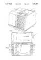
- FIG. 1is a perspective view of the portable table top humidifier constructed in accordance with the teachings of the present invention
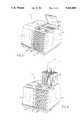
- FIG. 2is a top plan view of the portable table top humidifier shown in FIG. 1:
- FIG. 3is a front end view of the portable table top humidifier, with a partial fragmentary section revealing electronic components used in the motor control circuit of the humidifier;
- FIG. 4is a fragmentary side elevational view of the portable table top humidifier revealing the interior thereof, including the wicking element and motor driven fan assembly;
- FIG. 5is a diagrammatic illustration of the operation of the portable table top humidifier which illustrates the manner in which air is drawn into the humidifier and discharged therefrom after passing through the water absorbed wicking element thereof;
- FIG. 5Ais a diagrammatic illustration similar to FIG. 5, but showing the manner in which air is blown through the wick element by a different fan arrangement.
- FIG. 6is a diagrammatic view of the motor controlled circuit for the fan driven motor used in the humidifier
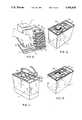
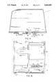
- FIG. 7is a perspective view illustrating the removable housing cover element for exposing the wicking element or filter
- FIG. 8is a perspective view of a portable table top humidifier illustrating the manner in which the wicking element or filter is removed or replaced relative to the humidifier;
- FIG. 9is a perspective view of the portable table top humidifier and illustrating the manner in which the water reservoir tank is removably mounted relative to the humidifier;
- FIG. 10is perspective view of the bottom of the water reservoir tank and illustrating the manner in which the removable fill cap is removed for filling the tank;
- FIG. 11is a bottom perspective view of the water reservoir tank illustrating filling thereof after removal of the removable fill cap;
- FIG. 12is bottom perspective view of the water reservoir tank illustrating the manner in which the removable fill cap is rotated into locking/sealing engagement relative to the water reservoir tank;
- FIG. 13is a perspective view of the portable table top humidifier with the water reservoir tank positioned upwardly from the supporting base thereof to expose the construction of the U-shaped channel underlying the water reservoir tank;
- FIG. 14is a top plan view of a modified form of portable table top humidifier which utilizes only a single control for operating same;
- FIG. 15is a side elevational sectional view of the water reservoir tank illustrating the manner in which the removable fill cap is threadably locked and sealed to the bottom of the water reservoir tank and including the spring biased valve stem with included valve seat for dispensing water from the water reservoir tank;
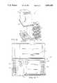
- FIG. 16is a top plan view of the supporting base of the portable table top humidifier, with the water reservoir tank, wicking element, motor assembly and housing removed therefrom;
- FIG. 17is an end elevational view of a one-piece injection molded motor frame including quick interconnect locking means for assembly of the motor frame to the supporting base;
- FIG. 18is a side elevational view of the one-piece injection molded motor frame illustrated in FIG. 17;
- FIG. 19is a top plan view of a rotary switch with complementary openings therein for receiving integral fastener studs from an overlying flexible panel in the second quick interconnect locking means associated with the motor frame;
- FIG. 20is a top plan view of a humidistat with complementary openings therein for receiving integral fastener studs from an overlying flexible panel in the second quick interconnect locking means associated with the motor frame for assembly of the humidistat thereto.
- the portable table top humidifier 1includes a supporting base 3 on which a housing 5 and a water reservoir tank 7 are mounted.
- a fan motor assembly 9including fan 11 and motor 13 which are energized by the operating air flow and humidity controls 15, 17 respectively, that will be subsequently discussed.
- a wicking element or filter 19that is positioned between rear of the housing 5 and the fan/motor assembly 9, for purposes to be subsequently discussed.
- the top of the housing 5includes a hinged cover 21 along an upper face of the housing, enabling the wicking element or filter -9 to be first exposed, as shown in FIG. 7, and then removed from the portable table top humidifier 1, as shown in FIG. 8 of the drawings, for cleaning or replacement.
- a series of air flow openings 23which are between adjacent pairs of the formed vertical and spaced struts 25 on housing 5.
- a directional louver control lever 31Extending from a centrally located air discharge opening 29 along the front face of the housing 5 is a directional louver control lever 31 for controlling the direction of moistened air discharged from the portable table top humidifier 1.
- the directional louver control lever 31is shown as being integrally attached to spaced horizontal louvers 33, through which moistened air may be first discharged and then through the air discharge openings 29. By moving the directional louver control lever 31 upwardly or downwardly as desired, the direction of the moistened air from the fan 11 through the air discharge openings 29 may be controlled.
- the water reservoir tank 7is constructed from a transparent plastic material for viewing the supply of water within the tank.
- the water reservoir tank 7is removably mounted relative to the supporting base 3 as a result of the lower outer rim 35 thereof being received within the complementary configured flange 37 formed in the supporting base 3 in the area where the water reservoir tank 7 is adapted to be positioned.
- the water reservoir tank 7When mounted on the supporting base 3 within the complementary configured flange 37 of the supporting base 3, the water reservoir tank 7 is constructed to dispense water as needed into a catch basin 39 formed in the supporting base.
- the catch basin 39as best seen in FIGS. 5, 13 and 16, includes a U-shaped channel 41 immediately below the water reservoir tank 7 which opens up into an enlarged receptacle 43 below the wick element 19 containing water and for receiving the lower end of the wick element 19 therewithin.
- the shape of the enlarged receptacle 43 of the catch basin 39is generally rectangular in shape to conform to the wick element or filter 19 for receiving the lower end of same therein.
- FIGS. 9-12 of the drawingsTo fill the water reservoir tank 7 with water, reference is made to FIGS. 9-12 of the drawings.
- the water reservoir tank 7is shown as being moved from the supporting base 3 of the portable table top humidifier 1 by grasping the lower rim 35 of the water reservoir tank 7 and lifting upward.
- the outer flange 37is interrupted along the front and rear face of the supporting base 3, as best seen in FIGS. 9, 13 and 16, in order to allow the user to grasp the lower rim 35 of the water reservoir tank 7 for lifting same.
- the water reservoir tank 7is inverted to expose the removable fill cap 45 as seen in FIG. 10.
- the center fill hole 47 in the bottom of the water reservoir tank 7is exposed, as shown in FIG. 11, to allow the water hole 47 to be placed under a water faucet for filling the water reservoir 7.
- the removable fill cap 45is re-installed and is hand tightened by twisting the removable fill cap in a clockwise direction, as shown by the arrow in FIG. 12 of the drawings.
- the removable fill cap 45is shown as being provided with external threads 49 for complementary mating engagement with internal threads 51 surrounding the water hole 47.
- an 0-ring or seal 53is provided immediately beneath and overhanging lip 55 of the removable fill cap 45, such that when hand tightened in a clockwise direction, the 0-ring or seal 53 is trapped between the overhanging lip 55 of the removable fill cap 45 and horizontal shoulder 57 formed in the water reservoir tank 7 surrounding the center hole 47. Thus, leaking of water from the water reservoir tank 7 is prevented.
- the water reservoir tank 7is provided with valve means 59, as best seen in FIG. 15, which is selectively responsive to the level of water within the catch basin 39 for dispensing water from the water reservoir tank 7 into the catch basin 39 when the water in the catch basin 39 is below a predetermined level.
- the valve means 59 of the water reservoir tank 7is mounted on a lower end thereof for engaging a valve activator 61 in the form of a fixed button activator that is located within the U-shaped channel 41 of the catch basin 39, to dispense water from the water reservoir tank 7.
- the valve means 59 of the water reservoir tank 7includes a spring biased valve stem 63 which is mounted on the shelf 65 within the tubular extension 67 that extends downwardly from end wall 69 and opens up into the water reservoir tank 7.
- the spring biased valve stem 63includes valve seat/seal 71 which is mounted at the upper end thereof for engaging the upper innermost portion 73 of the tubular extension 67, that opens up into the water reservoir tank 7.
- the spring biased valve stem 63is constructed to normally bias the valve seal/seat 71 into contact with the upper innermost inside wall portion 73 of the tubular extension 67, in order to prevent any water from being discharged through the tubular extension 67.
- the spring biased valve stem 63is positioned to engage the fixed button valve activator 61 within the U-shaped channel 41 of the catch basin 39, with the tubular extension 67 surrounding the button activator 61, to allow air to bleed into the water reservoir tank 7 for discharging water therefrom through the tubular extension 67.
- Water from the water reservoir tank 7is discharged or emptied into the catch basin 39, first through the U-shaped channel section 41 and then into the enlarged receptacle 43 thereof, until the water in the catch basin 39 reaches a predetermined level, which will then cut off air flow to the water reservoir tank.
- the wick element or filter 19is preferably constructed in a suitable sheet-like absorbent and capillary wick material, as described in detail in aforementioned U.S. Pat. No. 4,822,533.
- the unitary web of non-woven, fibrous and absorbent wicking mediamaintain its shape and physical properties when in contact with water for extended periods of time.
- This materialhas been selected because it has sufficient absorption capacity as well as sufficient capillary action such that with only the bottom of the wicking element or filter 19 submerged below the predetermined level of water within the catch basin 39, the wick element or filter 19 will absorb water and will wick the water vertically by capillary action along the entire height of the wicking element or filter 19 so that same is substantially uniformally wetted throughout.
- the wick element or filter 19begins to soak up the water immediately and becomes totally saturated in a short period of time, approximately thirty minutes.
- the humidifier 1can be operated to draw air into the rear of the humidifier through the air flow openings 23 by means of the fan motor assembly 9, allowing air to pass through the wicking element or filter 19 so that moisture is absorbed into the air and then released through the air discharge openings 29 in the front of the humidifier 1. Because all evaporation into the air takes place in the humidifier, moist air is released in the form of vapor, with no water droplets entering the home. Furthermore, any residue left by the evaporating water is not passed into the home, but remains in the wicking element or filter 19. As discussed above, the wicking element or filter 19 should be replaced, preferably once a season or more often under hard water conditions.
- FIGS. 1-6for the description of the air flow and humidity operating controls 15, 17.
- the air flow control 15is rotated from an off to a low or medium or high operation to cause the motor 13 to drive the fan 11 to low, medium or high flow output.
- the air flow control 15is connected to the switch 25 positioned therebelow, (shown in the cut out area of FIG. 3), for energizing the motor 13 to operate in low or medium or high operation.
- the humidity control 17when rotated to a "constant on" position, allows the maximum amount of humidity to be evaporated into the air continuously or rotated to a low or medium or high setting, where the humidifier will turn on and off to maintain the level of humidity selected.
- the humidity control 17is connected to the humidistat 77 also shown in the cut out portion of FIG. 3.
- the humidistat 77is electrically interconnected in the control circuit, as shown in FIG. 6 of the drawing, where 77 will turn the motor 13 on and off as required to maintain the level of humidity selected.
- the motor control circuit of FIG. 6further includes the rotary switch 75 and wall plug P which is connected to the cord C extending to the humidifier (See FIG. 4)
- the settingis allowed for constant on in order to provide a maximum amount of humidity to be evaporated into the air continuously.
- FIGS. 1-13 of the drawingsOperation of the portable table top humidifier 1 shown in FIGS. 1-13 of the drawings can best be understood by referring to FIG. 5 and the description that follows
- the humidifier 1will turn on and off as required to maintain the level of humidity selected or will operate continuously, by the humidity control 17 being pre-set in a "constant on” position.
- Dry heated airas represented by the arrows A in FIG. 5, will be drawn into the humidifier 1 by the fan motor assembly 9, so as to pass through the wicking element or filter 19.
- the wicking element or filter 19will absorb and allow sufficient water to flow up into the wicking element or filter 19 from the water in the catch basin 39, as a result of the lower end of the wicking element or filter 19 being positioned within catch basin 39. Water is absorbed up into the wick element or filter 19 by capillary action, as discussed above.
- the fan 11will draw dry heated air A, through the air inflow openings 23 in the rear of the humidifier, for contact with the wick element or filter 19.
- moistureis absorbed into the air and then released through the air discharge openings 29 in the front of the humidifier 1 in the form of moist air, represented by the arrows MA, in FIG. 5.
- the moist air MAis released in the form of vapor, rather than water droplets, because all evaporation into the air takes place within the confines of the humidifier. This also means that any residue left by the evaporating water will not be passed into the home, but will remain in the wicking element or filter 19.
- FIG. 5Ashows how air can be blown, instead of drawn through the wicking element 19, by a different fan arrangement.
- the humidifier usercan easily determine when the level of the water in the water reservoir tank 7 is low or depleted. As discussed in detail above, the water reservoir tank 7 can then be removed from the supporting base 3, to allow the water reservoir tank to be filled as has been previously shown and described in connection with FIGS. 9--12 of the drawings.
- valve means 59 in the water reservoir tank 7, which is in the form of the spring biased valve stem 63 with included valve seat/seal 71,is constructed to engage the fixed button activator 61 within the U-shaped channel 41 of the catch basin 39, with the tubular extension 67 extending thereover.
- the valve seat/seal 71will be disengaged on the upper innermost inner wall area 73 of the tubular extension 67 to allow air to bleed into the water reservoir tank for discharging water therefrom.
- the water level in the catch basin 39reaches a predetermined level, at which point, the water level in the catch basin 39 will cut-off air flow into the water reservoir tank 7 to stop water discharged therefrom.
- the humidifierwill run continuously until the air flow control 15 is turned off. Letting the humidifier 1 run until after the water reservoir tank 7 is empty will thoroughly dry the wicking element or filter 19 out. This will make it necessary to allow suffcient time for capillary action to wet the entire wicking element or filter 19, for subsequent efficient operation of the humidifier.
- FIG. 14 of the drawingsA modified form of portable table top humidifier is shown in FIG. 14 of the drawings. Similar reference numerals will be used to designate like parts in the FIGS. 1-13 embodiment.
- the humidifier 79differs from the humidifier 1 in the FIGS. 1-13 embodiment in that there is only an air flow control 81, rather than air flow and humidity controls 15, 17, as in the FIGS. 1-13 embodiment.
- FIG. 14contains no humidity control whatsoever, and is operated solely by the air flow control 81 which has a normal off as well as a low and high position.
- This more economical modelalso has a more simplified motor control circuit (not shown) without the humidistat 77 as shown in FIG. 6 of the FIGS. 1-13 embodiment. Nonetheless, the humidifier 79 will generally operate by converting dry air to moist air, along the lines of that described in connection with FIG. 5 of the drawings.
- FIGS. 16-20in the drawings for the unique way in which the fan motor assembly is supported and mounted relative to the supporting base 3 in the portable table top humidifier 1 of the present invention.
- FIGS. 17-18 of the drawingsthere is shown a one-piece injection molded plastic motor frame 81 with a motor supporting section 83 including the web section 85 at the rear of the motor support section 83, in order to hold the motor 13 therein.
- the motor frameFor assembly of the one-piece injection molded plastic motor frame 81 to the supporting base 3, the motor frame includes first quick interconnect locking means 87 provided on the motor frame 81 as well as the supporting base 3. Specifically, the motor frame includes, at the lower end thereof, a pair of spaced supporting feet 89, 89 for complementary reception within the elongated slot 91, provided in supporting base 3. It will be noted that each of the spaced supporting feet 89, 89 are positioned on opposite sides of a generally centrally positioned interlocking element 93 which is adapted to be interlocked within centrally positioned opening 105 provided in the elongated slot 91 of the supporting base 3.
- the lower end of the centrally positioned interlocking element 93are formed with locking teeth or steps 95 for interfitting and interlocking relationship within the opening 105 of the elongated slot.
- the web elements 85 at the rear of the motor support section 83include an opening 97 and spaced bosses 99, 99, to facilitate mounting the motor 13 within the motor support section 83, through various fastening elements 101, as generally shown in FIG. 4 of the drawings.
- the one-piece injection molded plastic motor frame 81further includes second quick interconnect locking means 103 for quick assembly of a rotary switch 75 shown in FIG. 19 and a humidistat 77 shown in FIG. 20 to the motor frame 81.
- the second quick interconnecting means 103includes an overlying flexible panel 109 having three integral studs 111 depending therefrom for complementary register with three holes 113 in the humidistat 77, along with an overlying flexible panel 115 and a pair of integral fastener studs 117, 117 depending therefrom for complementary register with the holes 119, 119 in the rotary switch 75.
- the overlying flexible panels 109 and 115may be interconnected together by a common wall 121, if desired.
- the rotary switch 75 and humidistat 77may be quickly and easily installed relative to the motor frame 81 through the aforementioned quick interconnect means 103, to permit stable and secure retention of same relative to the motor frame 81.
- Reference to FIG. 3 of the drawingsshows the manner in which the rotary switch and humidistat 75, 77 respectively are mounted in position in the motor frame 81 within the portable table top humidifier 1.
- the fan assembly 9is preferably located relative to the wick element 19 as shown in the drawings, it will also be appreciated that the fan assembly may be positioned to blow rather than draw air through the wick element 19. In broader terms, therefore, the fan assembly 9 is mounted relative to the wick element for directing (including drawing and/or blowing) air with increased humidity through the wick element for discharge from the humidifier into the surrounding atmosphere.
- the air inflow openingsmay be located on a face of the housing 5 other than the rear face thereof and the air discharge openings may also be located on a face of the housing 5 other than the front face thereof.
Landscapes
- Engineering & Computer Science (AREA)
- Chemical & Material Sciences (AREA)
- Combustion & Propulsion (AREA)
- Mechanical Engineering (AREA)
- General Engineering & Computer Science (AREA)
- Air Humidification (AREA)
Abstract
Description
Claims (21)
Priority Applications (2)
| Application Number | Priority Date | Filing Date | Title |
|---|---|---|---|
| US07/478,423US5061405A (en) | 1990-02-12 | 1990-02-12 | Constant humidity evaporative wicking filter humidifier |
| CA002021757ACA2021757C (en) | 1990-02-12 | 1990-07-23 | Constant humidity evaporative wicking filter humidifier |
Applications Claiming Priority (1)
| Application Number | Priority Date | Filing Date | Title |
|---|---|---|---|
| US07/478,423US5061405A (en) | 1990-02-12 | 1990-02-12 | Constant humidity evaporative wicking filter humidifier |
Publications (1)
| Publication Number | Publication Date |
|---|---|
| US5061405Atrue US5061405A (en) | 1991-10-29 |
Family
ID=23899868
Family Applications (1)
| Application Number | Title | Priority Date | Filing Date |
|---|---|---|---|
| US07/478,423Expired - LifetimeUS5061405A (en) | 1990-02-12 | 1990-02-12 | Constant humidity evaporative wicking filter humidifier |
Country Status (2)
| Country | Link |
|---|---|
| US (1) | US5061405A (en) |
| CA (1) | CA2021757C (en) |
Cited By (115)
| Publication number | Priority date | Publication date | Assignee | Title |
|---|---|---|---|---|
| US5143656A (en)* | 1991-10-28 | 1992-09-01 | Duracraft Corporation | Humidifier with a tamper proof liquid level responsive shut-off |
| US5143655A (en)* | 1991-07-08 | 1992-09-01 | Duracraft Corporation | Efficiently packaged humidifier device |
| USD337634S (en) | 1992-04-29 | 1993-07-20 | Bemis Manufacturing Company | Humidifier |
| US5447663A (en)* | 1994-03-15 | 1995-09-05 | Emerson Electric Co. | Floor mounted humidifier with wheeled water reservoir tank |
| US5480588A (en)* | 1994-12-05 | 1996-01-02 | Emerson Electric Co. | Humidifier with exposed spaced bottles |
| US5578113A (en)* | 1994-07-19 | 1996-11-26 | Holmes Product Corp. | Air treatment system |
| US5746359A (en)* | 1996-06-06 | 1998-05-05 | Emerson Electric Co. | Air seal for humidifier water bottle |
| US5783117A (en)* | 1997-01-09 | 1998-07-21 | Hunter Fan Company | Evaporative humidifier |
| US5792390A (en)* | 1996-01-11 | 1998-08-11 | Holmes Products Corp. | Humidifier with top fill tank |
| US5975502A (en)* | 1998-07-27 | 1999-11-02 | Emerson Electric Co. | Wick system for a humidifier and a method for operating the wick system |
| US6019355A (en)* | 1998-02-25 | 2000-02-01 | Honeywell Inc. | Contractible portable humidifier |
| WO2000033950A1 (en)* | 1998-12-07 | 2000-06-15 | Slant/Fin Corporation | Fill-in-place humidifier |
| USD449676S1 (en) | 2000-08-11 | 2001-10-23 | Hamilton Beach/Proctor-Silex, Inc. | Humidifier |
| US6427984B1 (en) | 2000-08-11 | 2002-08-06 | Hamilton Beach/Proctor-Silex, Inc. | Evaporative humidifier |
| US20030034573A1 (en)* | 2001-08-14 | 2003-02-20 | Hamilton Beach/Proctor-Silex, Inc. | Humidifier filter servicing and water level indicator |
| US20030136735A1 (en)* | 1996-12-17 | 2003-07-24 | Perriello Felix Anthony | Wastewater treatment with alkanes |
| US6622993B2 (en) | 2000-10-30 | 2003-09-23 | Hamilton Beach/Proctor-Silex, Inc. | Humidifier including output efficiency and liquid level indicators |
| US20030201227A1 (en)* | 1996-12-17 | 2003-10-30 | Perriello Felix Anthony | Remediation of odorous media |
| US20030234217A1 (en)* | 2001-05-15 | 2003-12-25 | Perriello Felix Anthony | Method and apparatus for treatment of septic systems with alkane-utilizing bacteria |
| US20050151280A1 (en)* | 2004-01-09 | 2005-07-14 | Jon French | Humidifier |
| USD513797S1 (en) | 2004-07-09 | 2006-01-24 | Burton, Inc. | Humidifier |
| US20070000489A1 (en)* | 2005-06-30 | 2007-01-04 | Shao-Shih Huang | Multi-function respiratory device |
| US20070075448A1 (en)* | 2005-10-05 | 2007-04-05 | Dirk Niedermann | Humidifier with adornment to simulate the appearance of a three dimensional object |
| US20070075446A1 (en)* | 2005-10-03 | 2007-04-05 | Glenn Bushee | Humidifier with sliding water tanks |
| USRE40298E1 (en)* | 1999-03-26 | 2008-05-06 | Lasko Holdings, Inc. | Insulated box fan |
| US20080148696A1 (en)* | 2006-12-22 | 2008-06-26 | Dirk Niedermann | Air purifier with housing simulating an animate object |
| US20090060710A1 (en)* | 2007-09-04 | 2009-03-05 | Dyson Technology Limited | Fan |
| US20100150699A1 (en)* | 2008-12-11 | 2010-06-17 | Dyson Technology Limited | Fan |
| GB2468328A (en)* | 2009-03-04 | 2010-09-08 | Dyson Technology Ltd | Fan assembly with humidifier |
| US20100226750A1 (en)* | 2009-03-04 | 2010-09-09 | Dyson Technology Limited | Fan assembly |
| US20100226771A1 (en)* | 2009-03-04 | 2010-09-09 | Dyson Technology Limited | Fan assembly |
| US20100225012A1 (en)* | 2009-03-04 | 2010-09-09 | Dyson Technology Limited | Humidifying apparatus |
| US20100254800A1 (en)* | 2008-09-23 | 2010-10-07 | Dyson Technology Limited | Fan |
| US20100258958A1 (en)* | 2007-09-18 | 2010-10-14 | Raymond Industrial Limited | Humidifier |
| US20110017212A1 (en)* | 2003-06-20 | 2011-01-27 | Resmed Limited | Breathable gas apparatus with humidifier |
| US8006691B2 (en)* | 2003-06-20 | 2011-08-30 | Resmed Limited | Humidifier with removable water tank |
| US8197226B2 (en) | 2009-03-04 | 2012-06-12 | Dyson Technology Limited | Fan assembly |
| US8246317B2 (en) | 2009-03-04 | 2012-08-21 | Dyson Technology Limited | Fan assembly |
| US8366403B2 (en) | 2010-08-06 | 2013-02-05 | Dyson Technology Limited | Fan assembly |
| US8403640B2 (en) | 2009-03-04 | 2013-03-26 | Dyson Technology Limited | Fan assembly |
| US8408869B2 (en) | 2009-03-04 | 2013-04-02 | Dyson Technology Limited | Fan assembly |
| US8430624B2 (en) | 2009-03-04 | 2013-04-30 | Dyson Technology Limited | Fan assembly |
| US8454322B2 (en) | 2009-11-06 | 2013-06-04 | Dyson Technology Limited | Fan having a magnetically attached remote control |
| WO2013082414A1 (en)* | 2011-12-01 | 2013-06-06 | Sunbeam Products, Inc. | Console humidifier |
| US8469660B2 (en) | 2009-03-04 | 2013-06-25 | Dyson Technology Limited | Fan assembly |
| US8469658B2 (en) | 2009-03-04 | 2013-06-25 | Dyson Technology Limited | Fan |
| US8613601B2 (en) | 2009-03-04 | 2013-12-24 | Dyson Technology Limited | Fan assembly |
| US8721286B2 (en) | 2009-03-04 | 2014-05-13 | Dyson Technology Limited | Fan assembly |
| US8734094B2 (en) | 2010-08-06 | 2014-05-27 | Dyson Technology Limited | Fan assembly |
| US8770946B2 (en) | 2010-03-23 | 2014-07-08 | Dyson Technology Limited | Accessory for a fan |
| US8789525B2 (en) | 2007-06-07 | 2014-07-29 | Resmed Limited | Tub for humidifier |
| US8873940B2 (en) | 2010-08-06 | 2014-10-28 | Dyson Technology Limited | Fan assembly |
| US8882451B2 (en) | 2010-03-23 | 2014-11-11 | Dyson Technology Limited | Fan |
| US8894354B2 (en) | 2010-09-07 | 2014-11-25 | Dyson Technology Limited | Fan |
| US8905384B2 (en) | 2011-04-24 | 2014-12-09 | Jeri Rodrigs | Room vent humidifier |
| US8967980B2 (en) | 2010-10-18 | 2015-03-03 | Dyson Technology Limited | Fan assembly |
| US8967979B2 (en) | 2010-10-18 | 2015-03-03 | Dyson Technology Limited | Fan assembly |
| US9011116B2 (en) | 2010-05-27 | 2015-04-21 | Dyson Technology Limited | Device for blowing air by means of a nozzle assembly |
| USD728092S1 (en) | 2013-08-01 | 2015-04-28 | Dyson Technology Limited | Fan |
| USD728769S1 (en) | 2013-08-01 | 2015-05-05 | Dyson Technology Limited | Fan |
| USD728770S1 (en) | 2013-08-01 | 2015-05-05 | Dyson Technology Limited | Fan |
| USD729373S1 (en) | 2013-03-07 | 2015-05-12 | Dyson Technology Limited | Fan |
| USD729376S1 (en) | 2013-03-07 | 2015-05-12 | Dyson Technology Limited | Fan |
| USD729375S1 (en) | 2013-03-07 | 2015-05-12 | Dyson Technology Limited | Fan |
| USD729374S1 (en) | 2013-03-07 | 2015-05-12 | Dyson Technology Limited | Fan |
| USD729372S1 (en) | 2013-03-07 | 2015-05-12 | Dyson Technology Limited | Fan |
| USD729925S1 (en) | 2013-03-07 | 2015-05-19 | Dyson Technology Limited | Fan |
| US9127689B2 (en) | 2009-03-04 | 2015-09-08 | Dyson Technology Limited | Fan assembly |
| US9127855B2 (en) | 2011-07-27 | 2015-09-08 | Dyson Technology Limited | Fan assembly |
| US9151299B2 (en) | 2012-02-06 | 2015-10-06 | Dyson Technology Limited | Fan |
| USD746425S1 (en) | 2013-01-18 | 2015-12-29 | Dyson Technology Limited | Humidifier |
| USD746966S1 (en) | 2013-01-18 | 2016-01-05 | Dyson Technology Limited | Humidifier |
| USD747450S1 (en) | 2013-01-18 | 2016-01-12 | Dyson Technology Limited | Humidifier |
| US9249809B2 (en) | 2012-02-06 | 2016-02-02 | Dyson Technology Limited | Fan |
| USD749231S1 (en) | 2013-01-18 | 2016-02-09 | Dyson Technology Limited | Humidifier |
| US9272116B2 (en) | 1999-08-05 | 2016-03-01 | Resmed R&D Germany Gmbh | Apparatus for humidifying a respiratory gas |
| US9283573B2 (en) | 2012-02-06 | 2016-03-15 | Dyson Technology Limited | Fan assembly |
| US9328739B2 (en) | 2012-01-19 | 2016-05-03 | Dyson Technology Limited | Fan |
| US9366449B2 (en) | 2012-03-06 | 2016-06-14 | Dyson Technology Limited | Humidifying apparatus |
| US9410711B2 (en) | 2013-09-26 | 2016-08-09 | Dyson Technology Limited | Fan assembly |
| US9458853B2 (en) | 2011-07-27 | 2016-10-04 | Dyson Technology Limited | Fan assembly |
| US9513028B2 (en) | 2009-03-04 | 2016-12-06 | Dyson Technology Limited | Fan assembly |
| US9568006B2 (en) | 2012-05-16 | 2017-02-14 | Dyson Technology Limited | Fan |
| US9568021B2 (en) | 2012-05-16 | 2017-02-14 | Dyson Technology Limited | Fan |
| US9599356B2 (en) | 2014-07-29 | 2017-03-21 | Dyson Technology Limited | Humidifying apparatus |
| US9732763B2 (en) | 2012-07-11 | 2017-08-15 | Dyson Technology Limited | Fan assembly |
| US9745996B2 (en) | 2010-12-02 | 2017-08-29 | Dyson Technology Limited | Fan |
| US9745981B2 (en) | 2011-11-11 | 2017-08-29 | Dyson Technology Limited | Fan assembly |
| US9752789B2 (en) | 2012-03-06 | 2017-09-05 | Dyson Technology Limited | Humidifying apparatus |
| US9797414B2 (en) | 2013-07-09 | 2017-10-24 | Dyson Technology Limited | Fan assembly |
| US9797612B2 (en) | 2013-01-29 | 2017-10-24 | Dyson Technology Limited | Fan assembly |
| US9797613B2 (en) | 2012-03-06 | 2017-10-24 | Dyson Technology Limited | Humidifying apparatus |
| US9816531B2 (en) | 2008-10-25 | 2017-11-14 | Dyson Technology Limited | Fan utilizing coanda surface |
| US9822778B2 (en) | 2012-04-19 | 2017-11-21 | Dyson Technology Limited | Fan assembly |
| WO2018029343A1 (en)* | 2016-08-12 | 2018-02-15 | Cerberus Ag | Air conditioner for humidifying room air using mineralized water |
| US9903602B2 (en) | 2014-07-29 | 2018-02-27 | Dyson Technology Limited | Humidifying apparatus |
| US9927136B2 (en) | 2012-03-06 | 2018-03-27 | Dyson Technology Limited | Fan assembly |
| US9926804B2 (en) | 2010-11-02 | 2018-03-27 | Dyson Technology Limited | Fan assembly |
| US9982677B2 (en) | 2014-07-29 | 2018-05-29 | Dyson Technology Limited | Fan assembly |
| US10094392B2 (en) | 2011-11-24 | 2018-10-09 | Dyson Technology Limited | Fan assembly |
| US10100836B2 (en) | 2010-10-13 | 2018-10-16 | Dyson Technology Limited | Fan assembly |
| US10145583B2 (en) | 2012-04-04 | 2018-12-04 | Dyson Technology Limited | Heating apparatus |
| US10234153B2 (en)* | 2012-02-29 | 2019-03-19 | Coway Co., Ltd. | Water leakage preventing humidification apparatus |
| US10408478B2 (en) | 2012-03-06 | 2019-09-10 | Dyson Technology Limited | Humidifying apparatus |
| US10428837B2 (en) | 2012-05-16 | 2019-10-01 | Dyson Technology Limited | Fan |
| US10465928B2 (en) | 2012-03-06 | 2019-11-05 | Dyson Technology Limited | Humidifying apparatus |
| US10612565B2 (en) | 2013-01-29 | 2020-04-07 | Dyson Technology Limited | Fan assembly |
| JP2020139725A (en)* | 2019-02-26 | 2020-09-03 | パナソニックIpマネジメント株式会社 | Liquid storage device for humidifier |
| USD899598S1 (en) | 2018-09-04 | 2020-10-20 | 3B Medical, Inc. | CPAP device |
| US10905836B2 (en) | 2015-04-02 | 2021-02-02 | Hill-Rom Services Pte. Ltd. | Manifold for respiratory device |
| US20220082273A1 (en)* | 2019-01-02 | 2022-03-17 | Dyson Technology Limited | Air treatment apparatus |
| US20220107100A1 (en)* | 2020-10-01 | 2022-04-07 | Hyku Home Inc | Room Humidifier |
| US11400247B2 (en) | 2016-12-22 | 2022-08-02 | Fisher & Paykel Healthcare Limited | Breathing assistance apparatus |
| US20230136098A1 (en)* | 2021-11-02 | 2023-05-04 | Shenzhen Miaoxin Technology Co., Ltd | Humidifier |
| US20230241343A1 (en)* | 2020-09-08 | 2023-08-03 | ResMed Pty Ltd | Humidification platform for use with a portable cpap device |
Families Citing this family (1)
| Publication number | Priority date | Publication date | Assignee | Title |
|---|---|---|---|---|
| EP1915577B1 (en) | 2005-08-19 | 2010-01-06 | Carl Freudenberg KG | Humidifier |
Citations (36)
| Publication number | Priority date | Publication date | Assignee | Title |
|---|---|---|---|---|
| US1367701A (en)* | 1918-12-20 | 1921-02-08 | John I Haynes | Humidifier |
| US1625663A (en)* | 1926-06-16 | 1927-04-19 | Charles F Keistler | Humidifier |
| US2031055A (en)* | 1933-10-30 | 1936-02-18 | Lucius Harlow Grimes | Air conditioning and refrigerating device |
| US2085390A (en)* | 1936-11-04 | 1937-06-29 | James G Quinlivan | Air cooler and humidifier |
| US2369623A (en)* | 1943-03-01 | 1945-02-13 | Ray C Utley | Hat steamer |
| US2379034A (en)* | 1944-05-06 | 1945-06-26 | Pargman Sydney | Automatic electric vaporizer |
| US2443417A (en)* | 1944-10-10 | 1948-06-15 | John K Duncan | Vaporizer |
| US2749725A (en)* | 1956-06-12 | Portable air conditioning apparatus | ||
| US2828953A (en)* | 1955-07-01 | 1958-04-01 | Dade Disinfecting Company Inc | Odorant dispenser |
| FR1261072A (en)* | 1960-06-27 | 1961-05-12 | Device for humidifying and purifying air in rooms | |
| US3045450A (en)* | 1960-03-30 | 1962-07-24 | Edward F Chandler | Air treating and cooling device |
| US3074698A (en)* | 1960-02-26 | 1963-01-22 | William T Sevald | Humidifier |
| US3188007A (en)* | 1962-04-16 | 1965-06-08 | Hankscraft Co | Humidifier |
| US3220707A (en)* | 1964-04-28 | 1965-11-30 | Fram Corp | Humidifiers |
| US3266481A (en)* | 1965-08-18 | 1966-08-16 | Lau Blower Co | Humidifier |
| US3283478A (en)* | 1964-06-24 | 1966-11-08 | Kaz Mfg Co Inc | Humidifier |
| US3290021A (en)* | 1963-11-29 | 1966-12-06 | Oster Mfg Co John | Portable humidifier |
| US3323784A (en)* | 1964-11-05 | 1967-06-06 | Peter A Fazio | Humidifier with throw-away reservoir |
| US3348822A (en)* | 1965-05-28 | 1967-10-24 | Sunbeam Corp | Humidifying device |
| US3376025A (en)* | 1964-02-29 | 1968-04-02 | Defensor | Equipment for humidifying air |
| US3598370A (en)* | 1969-07-14 | 1971-08-10 | Mc Graw Edison Co | Humidifier |
| US3852380A (en)* | 1973-05-24 | 1974-12-03 | Westinghouse Electric Corp | Water level indicator and control |
| US3864437A (en)* | 1970-11-16 | 1975-02-04 | Henry Blaszkowski | Humidifier |
| US3914349A (en)* | 1973-04-23 | 1975-10-21 | Sunbeam Corp | Portable humidifier |
| DE2604169A1 (en)* | 1976-02-04 | 1977-08-11 | Josef Kantorowicz | Water reservoir for air humidifier - is integrated to maintain operative water level constant to contact having absorbent material |
| US4117045A (en)* | 1976-09-23 | 1978-09-26 | Dart Industries Inc. | Humidifier with removable water receptacle |
| US4252547A (en)* | 1979-02-15 | 1981-02-24 | Johnson Kenneth O | Gas cleaning unit |
| US4362090A (en)* | 1979-08-21 | 1982-12-07 | Whiteley Isaac C | Air circulating device and method |
| US4540529A (en)* | 1985-03-08 | 1985-09-10 | Kathleen Koszyk | Compact portable humidifier |
| US4624806A (en)* | 1985-03-08 | 1986-11-25 | Kathleen Koszyk | Compact portable humidifier |
| US4699737A (en)* | 1986-07-09 | 1987-10-13 | Engstrand Bradley W | Portable humidifier |
| US4719057A (en)* | 1984-04-02 | 1988-01-12 | Sharp Kabushiki Kaisha | Humidifier blowoff portion |
| US4810854A (en)* | 1987-05-26 | 1989-03-07 | Sunbeam Corporation | Compact portable vaporizer |
| US4822533A (en)* | 1986-12-11 | 1989-04-18 | Emerson Electric Co. | Humidifier with floating wick assembly and replaceable wick elements |
| US4853161A (en)* | 1987-10-27 | 1989-08-01 | Han Chi Hang Co., Ltd. | Auto turning-off humidifier |
| US4921639A (en)* | 1988-11-09 | 1990-05-01 | Bernard Chiu | Ultrasonic humidifier |
- 1990
- 1990-02-12USUS07/478,423patent/US5061405A/ennot_activeExpired - Lifetime
- 1990-07-23CACA002021757Apatent/CA2021757C/ennot_activeExpired - Lifetime
Patent Citations (37)
| Publication number | Priority date | Publication date | Assignee | Title |
|---|---|---|---|---|
| US2749725A (en)* | 1956-06-12 | Portable air conditioning apparatus | ||
| US1367701A (en)* | 1918-12-20 | 1921-02-08 | John I Haynes | Humidifier |
| US1625663A (en)* | 1926-06-16 | 1927-04-19 | Charles F Keistler | Humidifier |
| US2031055A (en)* | 1933-10-30 | 1936-02-18 | Lucius Harlow Grimes | Air conditioning and refrigerating device |
| US2085390A (en)* | 1936-11-04 | 1937-06-29 | James G Quinlivan | Air cooler and humidifier |
| US2369623A (en)* | 1943-03-01 | 1945-02-13 | Ray C Utley | Hat steamer |
| US2379034A (en)* | 1944-05-06 | 1945-06-26 | Pargman Sydney | Automatic electric vaporizer |
| US2443417A (en)* | 1944-10-10 | 1948-06-15 | John K Duncan | Vaporizer |
| US2828953A (en)* | 1955-07-01 | 1958-04-01 | Dade Disinfecting Company Inc | Odorant dispenser |
| US3074698A (en)* | 1960-02-26 | 1963-01-22 | William T Sevald | Humidifier |
| US3045450A (en)* | 1960-03-30 | 1962-07-24 | Edward F Chandler | Air treating and cooling device |
| FR1261072A (en)* | 1960-06-27 | 1961-05-12 | Device for humidifying and purifying air in rooms | |
| US3188007A (en)* | 1962-04-16 | 1965-06-08 | Hankscraft Co | Humidifier |
| US3290021A (en)* | 1963-11-29 | 1966-12-06 | Oster Mfg Co John | Portable humidifier |
| US3376025A (en)* | 1964-02-29 | 1968-04-02 | Defensor | Equipment for humidifying air |
| US3220707A (en)* | 1964-04-28 | 1965-11-30 | Fram Corp | Humidifiers |
| US3283478A (en)* | 1964-06-24 | 1966-11-08 | Kaz Mfg Co Inc | Humidifier |
| US3323784A (en)* | 1964-11-05 | 1967-06-06 | Peter A Fazio | Humidifier with throw-away reservoir |
| US3348822A (en)* | 1965-05-28 | 1967-10-24 | Sunbeam Corp | Humidifying device |
| US3266481A (en)* | 1965-08-18 | 1966-08-16 | Lau Blower Co | Humidifier |
| US3598370A (en)* | 1969-07-14 | 1971-08-10 | Mc Graw Edison Co | Humidifier |
| US3864437A (en)* | 1970-11-16 | 1975-02-04 | Henry Blaszkowski | Humidifier |
| US3914349A (en)* | 1973-04-23 | 1975-10-21 | Sunbeam Corp | Portable humidifier |
| US3852380A (en)* | 1973-05-24 | 1974-12-03 | Westinghouse Electric Corp | Water level indicator and control |
| DE2604169A1 (en)* | 1976-02-04 | 1977-08-11 | Josef Kantorowicz | Water reservoir for air humidifier - is integrated to maintain operative water level constant to contact having absorbent material |
| US4117045A (en)* | 1976-09-23 | 1978-09-26 | Dart Industries Inc. | Humidifier with removable water receptacle |
| US4252547A (en)* | 1979-02-15 | 1981-02-24 | Johnson Kenneth O | Gas cleaning unit |
| US4362090A (en)* | 1979-08-21 | 1982-12-07 | Whiteley Isaac C | Air circulating device and method |
| US4719057A (en)* | 1984-04-02 | 1988-01-12 | Sharp Kabushiki Kaisha | Humidifier blowoff portion |
| US4540529A (en)* | 1985-03-08 | 1985-09-10 | Kathleen Koszyk | Compact portable humidifier |
| US4624806A (en)* | 1985-03-08 | 1986-11-25 | Kathleen Koszyk | Compact portable humidifier |
| US4699737A (en)* | 1986-07-09 | 1987-10-13 | Engstrand Bradley W | Portable humidifier |
| US4822533A (en)* | 1986-12-11 | 1989-04-18 | Emerson Electric Co. | Humidifier with floating wick assembly and replaceable wick elements |
| US4865775A (en)* | 1986-12-11 | 1989-09-12 | Emerson Electric Co. | Humidifier with floating wick assembly |
| US4810854A (en)* | 1987-05-26 | 1989-03-07 | Sunbeam Corporation | Compact portable vaporizer |
| US4853161A (en)* | 1987-10-27 | 1989-08-01 | Han Chi Hang Co., Ltd. | Auto turning-off humidifier |
| US4921639A (en)* | 1988-11-09 | 1990-05-01 | Bernard Chiu | Ultrasonic humidifier |
Cited By (200)
| Publication number | Priority date | Publication date | Assignee | Title |
|---|---|---|---|---|
| US5143655A (en)* | 1991-07-08 | 1992-09-01 | Duracraft Corporation | Efficiently packaged humidifier device |
| US5143656A (en)* | 1991-10-28 | 1992-09-01 | Duracraft Corporation | Humidifier with a tamper proof liquid level responsive shut-off |
| USD337634S (en) | 1992-04-29 | 1993-07-20 | Bemis Manufacturing Company | Humidifier |
| US5447663A (en)* | 1994-03-15 | 1995-09-05 | Emerson Electric Co. | Floor mounted humidifier with wheeled water reservoir tank |
| US5578113A (en)* | 1994-07-19 | 1996-11-26 | Holmes Product Corp. | Air treatment system |
| US5480588A (en)* | 1994-12-05 | 1996-01-02 | Emerson Electric Co. | Humidifier with exposed spaced bottles |
| US5792390A (en)* | 1996-01-11 | 1998-08-11 | Holmes Products Corp. | Humidifier with top fill tank |
| US5746359A (en)* | 1996-06-06 | 1998-05-05 | Emerson Electric Co. | Air seal for humidifier water bottle |
| US20030136735A1 (en)* | 1996-12-17 | 2003-07-24 | Perriello Felix Anthony | Wastewater treatment with alkanes |
| US7182871B2 (en) | 1996-12-17 | 2007-02-27 | Global Biosciences, Inc. | Wastewater treatment with alkanes |
| US20030201227A1 (en)* | 1996-12-17 | 2003-10-30 | Perriello Felix Anthony | Remediation of odorous media |
| US5783117A (en)* | 1997-01-09 | 1998-07-21 | Hunter Fan Company | Evaporative humidifier |
| US6019355A (en)* | 1998-02-25 | 2000-02-01 | Honeywell Inc. | Contractible portable humidifier |
| US5975502A (en)* | 1998-07-27 | 1999-11-02 | Emerson Electric Co. | Wick system for a humidifier and a method for operating the wick system |
| WO2000033950A1 (en)* | 1998-12-07 | 2000-06-15 | Slant/Fin Corporation | Fill-in-place humidifier |
| US6098963A (en)* | 1998-12-07 | 2000-08-08 | Slant/Fin Corporation | Fill-in-place humidifier |
| USRE40298E1 (en)* | 1999-03-26 | 2008-05-06 | Lasko Holdings, Inc. | Insulated box fan |
| US9555211B2 (en) | 1999-08-05 | 2017-01-31 | Resmed R&D Germany Gmbh | Apparatus for humidifying a respiratory gas |
| US9545493B2 (en) | 1999-08-05 | 2017-01-17 | Resmed R&D Germany Gmbh | Apparatus for humidifying a respiratory gas |
| US9884163B2 (en) | 1999-08-05 | 2018-02-06 | RedMed R&D Germany GmbH | Apparatus for humidifying a respiratory gas |
| US9545494B2 (en) | 1999-08-05 | 2017-01-17 | Resmed R&D Germany Gmbh | Apparatus for humidifying a respiratory gas |
| US10052450B2 (en) | 1999-08-05 | 2018-08-21 | Resmed R&D Germany Gmbh | Apparatus for humidifying a respiratory gas |
| US9302067B2 (en) | 1999-08-05 | 2016-04-05 | Resmed R&D Germany Gmbh | Apparatus for humidifying a respiratory gas |
| US9272116B2 (en) | 1999-08-05 | 2016-03-01 | Resmed R&D Germany Gmbh | Apparatus for humidifying a respiratory gas |
| US20040012103A1 (en)* | 2000-08-11 | 2004-01-22 | Hamilton Beach/Proctor-Silex, Inc. | Evaporative humidifier |
| US6715739B2 (en) | 2000-08-11 | 2004-04-06 | Hamilton Beach/Proctor-Silex, Inc. | Evaporative humidifier |
| US6604733B2 (en) | 2000-08-11 | 2003-08-12 | Hamilton Beach/Proctor-Silex, Inc. | Evaporative humidifier |
| US6427984B1 (en) | 2000-08-11 | 2002-08-06 | Hamilton Beach/Proctor-Silex, Inc. | Evaporative humidifier |
| USD449676S1 (en) | 2000-08-11 | 2001-10-23 | Hamilton Beach/Proctor-Silex, Inc. | Humidifier |
| US6622993B2 (en) | 2000-10-30 | 2003-09-23 | Hamilton Beach/Proctor-Silex, Inc. | Humidifier including output efficiency and liquid level indicators |
| US6835312B2 (en) | 2001-05-15 | 2004-12-28 | Global Biosciences, Inc. | Method and apparatus for treatment of septic systems with alkane-utilizing bacteria |
| US20030234217A1 (en)* | 2001-05-15 | 2003-12-25 | Perriello Felix Anthony | Method and apparatus for treatment of septic systems with alkane-utilizing bacteria |
| US6796550B2 (en) | 2001-08-14 | 2004-09-28 | Hamilton Beach/Proctor-Silex, Inc. | Humidifier filter servicing and water level indicator |
| US20030034573A1 (en)* | 2001-08-14 | 2003-02-20 | Hamilton Beach/Proctor-Silex, Inc. | Humidifier filter servicing and water level indicator |
| USRE46543E1 (en) | 2003-06-20 | 2017-09-12 | Resmed Limited | Breathable gas apparatus with humidifier |
| US9539409B2 (en) | 2003-06-20 | 2017-01-10 | Resmed Limited | Breathable gas apparatus with humidifier |
| US11413412B2 (en) | 2003-06-20 | 2022-08-16 | ResMed Pty Ltd | Breathable gas supply apparatus |
| US11260187B2 (en) | 2003-06-20 | 2022-03-01 | ResMed Pty Ltd | Breathable gas supply apparatus |
| US11235115B2 (en) | 2003-06-20 | 2022-02-01 | ResMed Pty Ltd | Breathable gas apparatus with humidifier |
| US10881820B2 (en) | 2003-06-20 | 2021-01-05 | ResMed Pty Ltd | Breathable gas apparatus with humidifier |
| US10850053B2 (en) | 2003-06-20 | 2020-12-01 | ResMed Pty Ltd | Breathable gas supply apparatus |
| US10293125B2 (en) | 2003-06-20 | 2019-05-21 | Resmed Limited | Flow generator with patient reminder |
| CN104353165B (en)* | 2003-06-20 | 2017-08-22 | 瑞思迈有限公司 | Breathable gas apparatus with humidifier |
| US9038632B2 (en) | 2003-06-20 | 2015-05-26 | Resmed Limited | Breathable gas apparatus with humidifier |
| US9038631B2 (en) | 2003-06-20 | 2015-05-26 | Resmed Limited | Breathable gas apparatus with humidifier |
| US20110017212A1 (en)* | 2003-06-20 | 2011-01-27 | Resmed Limited | Breathable gas apparatus with humidifier |
| US20110023877A1 (en)* | 2003-06-20 | 2011-02-03 | Resmed Limited | Breathable gas apparatus with humidifier |
| US9072860B2 (en) | 2003-06-20 | 2015-07-07 | Resmed Limited | Breathable gas apparatus with humidifier |
| US20170182270A1 (en)* | 2003-06-20 | 2017-06-29 | Resmed Limited | Acoustic damping for blower in cpap device / pap device with noise reducing enclosure |
| US8006691B2 (en)* | 2003-06-20 | 2011-08-30 | Resmed Limited | Humidifier with removable water tank |
| US8020551B2 (en)* | 2003-06-20 | 2011-09-20 | Resmed Limited | Breathable gas apparatus with humidifier |
| US8028693B2 (en)* | 2003-06-20 | 2011-10-04 | Resmed Limited | Breathable gas apparatus with humidifier |
| US8042535B2 (en) | 2003-06-20 | 2011-10-25 | Resmed Limited | Breathable gas apparatus with humidifier |
| US9610420B2 (en) | 2003-06-20 | 2017-04-04 | Resmed Limited | Breathable gas apparatus with humidifier |
| US9227035B2 (en) | 2003-06-20 | 2016-01-05 | Resmed Limited | Breathable gas apparatus with humidifier |
| US10201676B2 (en) | 2003-06-20 | 2019-02-12 | Resmed Limited | Breathable gas supply apparatus |
| US9358359B2 (en) | 2003-06-20 | 2016-06-07 | Resmed Limited | Breathable gas apparatus with humidifier |
| US20060170121A1 (en)* | 2004-01-09 | 2006-08-03 | Jcs/Thg, Llc. | Humidifier |
| US7073782B2 (en) | 2004-01-09 | 2006-07-11 | Jcs/Thg, Llc | Humidifier |
| US20050151280A1 (en)* | 2004-01-09 | 2005-07-14 | Jon French | Humidifier |
| US7377494B2 (en) | 2004-01-09 | 2008-05-27 | Sunbeam Products, Inc. | Humidifier |
| USD513797S1 (en) | 2004-07-09 | 2006-01-24 | Burton, Inc. | Humidifier |
| US20070000489A1 (en)* | 2005-06-30 | 2007-01-04 | Shao-Shih Huang | Multi-function respiratory device |
| US20070075446A1 (en)* | 2005-10-03 | 2007-04-05 | Glenn Bushee | Humidifier with sliding water tanks |
| US7441756B2 (en)* | 2005-10-05 | 2008-10-28 | Wachsmuth And Krogmann, Inc. | Humidifier with adornment to simulate the appearance of a three dimensional object |
| US20070075448A1 (en)* | 2005-10-05 | 2007-04-05 | Dirk Niedermann | Humidifier with adornment to simulate the appearance of a three dimensional object |
| US20080148696A1 (en)* | 2006-12-22 | 2008-06-26 | Dirk Niedermann | Air purifier with housing simulating an animate object |
| US8789525B2 (en) | 2007-06-07 | 2014-07-29 | Resmed Limited | Tub for humidifier |
| US12011545B2 (en) | 2007-06-07 | 2024-06-18 | ResMed Pty Ltd | Tub for humidifier |
| US10478585B2 (en) | 2007-06-07 | 2019-11-19 | ResMed Pty Ltd | Tub for humidifier |
| US20090060710A1 (en)* | 2007-09-04 | 2009-03-05 | Dyson Technology Limited | Fan |
| US8403650B2 (en) | 2007-09-04 | 2013-03-26 | Dyson Technology Limited | Fan |
| US9249810B2 (en) | 2007-09-04 | 2016-02-02 | Dyson Technology Limited | Fan |
| US8764412B2 (en) | 2007-09-04 | 2014-07-01 | Dyson Technology Limited | Fan |
| US8308445B2 (en) | 2007-09-04 | 2012-11-13 | Dyson Technology Limited | Fan |
| US20100258958A1 (en)* | 2007-09-18 | 2010-10-14 | Raymond Industrial Limited | Humidifier |
| US7931449B2 (en) | 2008-09-23 | 2011-04-26 | Dyson Technology Limited | Fan |
| US20100254800A1 (en)* | 2008-09-23 | 2010-10-07 | Dyson Technology Limited | Fan |
| US8348629B2 (en) | 2008-09-23 | 2013-01-08 | Dyston Technology Limited | Fan |
| US10145388B2 (en) | 2008-10-25 | 2018-12-04 | Dyson Technology Limited | Fan with a filter |
| US9816531B2 (en) | 2008-10-25 | 2017-11-14 | Dyson Technology Limited | Fan utilizing coanda surface |
| US20100150699A1 (en)* | 2008-12-11 | 2010-06-17 | Dyson Technology Limited | Fan |
| US8092166B2 (en) | 2008-12-11 | 2012-01-10 | Dyson Technology Limited | Fan |
| US8529203B2 (en) | 2009-03-04 | 2013-09-10 | Dyson Technology Limited | Fan assembly |
| US8403640B2 (en) | 2009-03-04 | 2013-03-26 | Dyson Technology Limited | Fan assembly |
| US8784049B2 (en) | 2009-03-04 | 2014-07-22 | Dyson Technology Limited | Fan |
| US8784071B2 (en) | 2009-03-04 | 2014-07-22 | Dyson Technology Limited | Fan assembly |
| GB2468328A (en)* | 2009-03-04 | 2010-09-08 | Dyson Technology Ltd | Fan assembly with humidifier |
| US20100226750A1 (en)* | 2009-03-04 | 2010-09-09 | Dyson Technology Limited | Fan assembly |
| US20100226771A1 (en)* | 2009-03-04 | 2010-09-09 | Dyson Technology Limited | Fan assembly |
| US20100225012A1 (en)* | 2009-03-04 | 2010-09-09 | Dyson Technology Limited | Humidifying apparatus |
| US8932028B2 (en) | 2009-03-04 | 2015-01-13 | Dyson Technology Limited | Fan assembly |
| US7972111B2 (en) | 2009-03-04 | 2011-07-05 | Dyson Technology Limited | Fan assembly |
| US8052379B2 (en) | 2009-03-04 | 2011-11-08 | Dyson Technology Limited | Fan assembly |
| US10006657B2 (en) | 2009-03-04 | 2018-06-26 | Dyson Technology Limited | Fan assembly |
| US9599368B2 (en) | 2009-03-04 | 2017-03-21 | Dyson Technology Limited | Nozzle for bladeless fan assembly with heater |
| US8197226B2 (en) | 2009-03-04 | 2012-06-12 | Dyson Technology Limited | Fan assembly |
| US8246317B2 (en) | 2009-03-04 | 2012-08-21 | Dyson Technology Limited | Fan assembly |
| US8721286B2 (en) | 2009-03-04 | 2014-05-13 | Dyson Technology Limited | Fan assembly |
| US8714937B2 (en) | 2009-03-04 | 2014-05-06 | Dyson Technology Limited | Fan assembly |
| US8708650B2 (en) | 2009-03-04 | 2014-04-29 | Dyson Technology Limited | Fan assembly |
| US8684687B2 (en) | 2009-03-04 | 2014-04-01 | Dyson Technology Limited | Fan assembly |
| US8613601B2 (en) | 2009-03-04 | 2013-12-24 | Dyson Technology Limited | Fan assembly |
| US8308432B2 (en) | 2009-03-04 | 2012-11-13 | Dyson Technology Limited | Fan assembly |
| US8469658B2 (en) | 2009-03-04 | 2013-06-25 | Dyson Technology Limited | Fan |
| US8469660B2 (en) | 2009-03-04 | 2013-06-25 | Dyson Technology Limited | Fan assembly |
| US8469655B2 (en) | 2009-03-04 | 2013-06-25 | Dyson Technology Limited | Fan assembly |
| AU2010220190B2 (en)* | 2009-03-04 | 2012-11-15 | Dyson Technology Limited | Humidifying apparatus |
| US9127689B2 (en) | 2009-03-04 | 2015-09-08 | Dyson Technology Limited | Fan assembly |
| US8348596B2 (en) | 2009-03-04 | 2013-01-08 | Dyson Technology Limited | Fan assembly |
| US9513028B2 (en) | 2009-03-04 | 2016-12-06 | Dyson Technology Limited | Fan assembly |
| US8348597B2 (en) | 2009-03-04 | 2013-01-08 | Dyson Technology Limited | Fan assembly |
| US10221860B2 (en) | 2009-03-04 | 2019-03-05 | Dyson Technology Limited | Fan assembly |
| US8356804B2 (en) | 2009-03-04 | 2013-01-22 | Dyson Technology Limited | Humidifying apparatus |
| US8430624B2 (en) | 2009-03-04 | 2013-04-30 | Dyson Technology Limited | Fan assembly |
| US8408869B2 (en) | 2009-03-04 | 2013-04-02 | Dyson Technology Limited | Fan assembly |
| US8783663B2 (en) | 2009-03-04 | 2014-07-22 | Dyson Technology Limited | Humidifying apparatus |
| US9004878B2 (en) | 2009-11-06 | 2015-04-14 | Dyson Technology Limited | Fan having a magnetically attached remote control |
| US8454322B2 (en) | 2009-11-06 | 2013-06-04 | Dyson Technology Limited | Fan having a magnetically attached remote control |
| US8882451B2 (en) | 2010-03-23 | 2014-11-11 | Dyson Technology Limited | Fan |
| US8770946B2 (en) | 2010-03-23 | 2014-07-08 | Dyson Technology Limited | Accessory for a fan |
| US9011116B2 (en) | 2010-05-27 | 2015-04-21 | Dyson Technology Limited | Device for blowing air by means of a nozzle assembly |
| US10344773B2 (en) | 2010-08-06 | 2019-07-09 | Dyson Technology Limited | Fan assembly |
| US8366403B2 (en) | 2010-08-06 | 2013-02-05 | Dyson Technology Limited | Fan assembly |
| US8873940B2 (en) | 2010-08-06 | 2014-10-28 | Dyson Technology Limited | Fan assembly |
| US8734094B2 (en) | 2010-08-06 | 2014-05-27 | Dyson Technology Limited | Fan assembly |
| US9745988B2 (en) | 2010-09-07 | 2017-08-29 | Dyson Technology Limited | Fan |
| US8894354B2 (en) | 2010-09-07 | 2014-11-25 | Dyson Technology Limited | Fan |
| US10100836B2 (en) | 2010-10-13 | 2018-10-16 | Dyson Technology Limited | Fan assembly |
| US8967980B2 (en) | 2010-10-18 | 2015-03-03 | Dyson Technology Limited | Fan assembly |
| US8967979B2 (en) | 2010-10-18 | 2015-03-03 | Dyson Technology Limited | Fan assembly |
| US9926804B2 (en) | 2010-11-02 | 2018-03-27 | Dyson Technology Limited | Fan assembly |
| US9745996B2 (en) | 2010-12-02 | 2017-08-29 | Dyson Technology Limited | Fan |
| US8905384B2 (en) | 2011-04-24 | 2014-12-09 | Jeri Rodrigs | Room vent humidifier |
| US9127855B2 (en) | 2011-07-27 | 2015-09-08 | Dyson Technology Limited | Fan assembly |
| US10094581B2 (en) | 2011-07-27 | 2018-10-09 | Dyson Technology Limited | Fan assembly |
| US9335064B2 (en) | 2011-07-27 | 2016-05-10 | Dyson Technology Limited | Fan assembly |
| US9291361B2 (en) | 2011-07-27 | 2016-03-22 | Dyson Technology Limited | Fan assembly |
| US9458853B2 (en) | 2011-07-27 | 2016-10-04 | Dyson Technology Limited | Fan assembly |
| US9745981B2 (en) | 2011-11-11 | 2017-08-29 | Dyson Technology Limited | Fan assembly |
| US10094392B2 (en) | 2011-11-24 | 2018-10-09 | Dyson Technology Limited | Fan assembly |
| WO2013082414A1 (en)* | 2011-12-01 | 2013-06-06 | Sunbeam Products, Inc. | Console humidifier |
| US9423141B2 (en) | 2011-12-01 | 2016-08-23 | Sunbeam Products, Inc. | Console humidifier |
| US9328739B2 (en) | 2012-01-19 | 2016-05-03 | Dyson Technology Limited | Fan |
| US9249809B2 (en) | 2012-02-06 | 2016-02-02 | Dyson Technology Limited | Fan |
| US9151299B2 (en) | 2012-02-06 | 2015-10-06 | Dyson Technology Limited | Fan |
| US9283573B2 (en) | 2012-02-06 | 2016-03-15 | Dyson Technology Limited | Fan assembly |
| US10234153B2 (en)* | 2012-02-29 | 2019-03-19 | Coway Co., Ltd. | Water leakage preventing humidification apparatus |
| US9797613B2 (en) | 2012-03-06 | 2017-10-24 | Dyson Technology Limited | Humidifying apparatus |
| US9366449B2 (en) | 2012-03-06 | 2016-06-14 | Dyson Technology Limited | Humidifying apparatus |
| US10563875B2 (en) | 2012-03-06 | 2020-02-18 | Dyson Technology Limited | Humidifying apparatus |
| US9752789B2 (en) | 2012-03-06 | 2017-09-05 | Dyson Technology Limited | Humidifying apparatus |
| US10465928B2 (en) | 2012-03-06 | 2019-11-05 | Dyson Technology Limited | Humidifying apparatus |
| US10408478B2 (en) | 2012-03-06 | 2019-09-10 | Dyson Technology Limited | Humidifying apparatus |
| US9927136B2 (en) | 2012-03-06 | 2018-03-27 | Dyson Technology Limited | Fan assembly |
| US10145583B2 (en) | 2012-04-04 | 2018-12-04 | Dyson Technology Limited | Heating apparatus |
| US9822778B2 (en) | 2012-04-19 | 2017-11-21 | Dyson Technology Limited | Fan assembly |
| US9568006B2 (en) | 2012-05-16 | 2017-02-14 | Dyson Technology Limited | Fan |
| US10309420B2 (en) | 2012-05-16 | 2019-06-04 | Dyson Technology Limited | Fan |
| US9568021B2 (en) | 2012-05-16 | 2017-02-14 | Dyson Technology Limited | Fan |
| US10428837B2 (en) | 2012-05-16 | 2019-10-01 | Dyson Technology Limited | Fan |
| US9732763B2 (en) | 2012-07-11 | 2017-08-15 | Dyson Technology Limited | Fan assembly |
| USD746966S1 (en) | 2013-01-18 | 2016-01-05 | Dyson Technology Limited | Humidifier |
| USD749231S1 (en) | 2013-01-18 | 2016-02-09 | Dyson Technology Limited | Humidifier |
| USD746425S1 (en) | 2013-01-18 | 2015-12-29 | Dyson Technology Limited | Humidifier |
| USD747450S1 (en) | 2013-01-18 | 2016-01-12 | Dyson Technology Limited | Humidifier |
| US10612565B2 (en) | 2013-01-29 | 2020-04-07 | Dyson Technology Limited | Fan assembly |
| US9797612B2 (en) | 2013-01-29 | 2017-10-24 | Dyson Technology Limited | Fan assembly |
| USD729374S1 (en) | 2013-03-07 | 2015-05-12 | Dyson Technology Limited | Fan |
| USD729376S1 (en) | 2013-03-07 | 2015-05-12 | Dyson Technology Limited | Fan |
| USD729925S1 (en) | 2013-03-07 | 2015-05-19 | Dyson Technology Limited | Fan |
| USD729375S1 (en) | 2013-03-07 | 2015-05-12 | Dyson Technology Limited | Fan |
| USD729372S1 (en) | 2013-03-07 | 2015-05-12 | Dyson Technology Limited | Fan |
| USD729373S1 (en) | 2013-03-07 | 2015-05-12 | Dyson Technology Limited | Fan |
| US9797414B2 (en) | 2013-07-09 | 2017-10-24 | Dyson Technology Limited | Fan assembly |
| USD728769S1 (en) | 2013-08-01 | 2015-05-05 | Dyson Technology Limited | Fan |
| USD728770S1 (en) | 2013-08-01 | 2015-05-05 | Dyson Technology Limited | Fan |
| USD728092S1 (en) | 2013-08-01 | 2015-04-28 | Dyson Technology Limited | Fan |
| US9410711B2 (en) | 2013-09-26 | 2016-08-09 | Dyson Technology Limited | Fan assembly |
| US9903602B2 (en) | 2014-07-29 | 2018-02-27 | Dyson Technology Limited | Humidifying apparatus |
| US9982677B2 (en) | 2014-07-29 | 2018-05-29 | Dyson Technology Limited | Fan assembly |
| US9599356B2 (en) | 2014-07-29 | 2017-03-21 | Dyson Technology Limited | Humidifying apparatus |
| US10905836B2 (en) | 2015-04-02 | 2021-02-02 | Hill-Rom Services Pte. Ltd. | Manifold for respiratory device |
| US10905837B2 (en) | 2015-04-02 | 2021-02-02 | Hill-Rom Services Pte. Ltd. | Respiratory therapy cycle control and feedback |
| US11992611B2 (en) | 2015-04-02 | 2024-05-28 | Hill-Rom Services Pte. Ltd. | Respiratory therapy apparatus control |
| CN109642744B (en)* | 2016-08-12 | 2022-02-18 | 博尔乐有限公司 | Air conditioning equipment for humidifying indoor air by using mineralized water |
| WO2018029343A1 (en)* | 2016-08-12 | 2018-02-15 | Cerberus Ag | Air conditioner for humidifying room air using mineralized water |
| CN109642744A (en)* | 2016-08-12 | 2019-04-16 | 博尔乐有限公司 | The air-conditioning equipment that room air is humidified using mineralized water |
| US11400247B2 (en) | 2016-12-22 | 2022-08-02 | Fisher & Paykel Healthcare Limited | Breathing assistance apparatus |
| US12168097B2 (en) | 2016-12-22 | 2024-12-17 | Fisher & Paykel Healthcare Limited | Breathing assistance apparatus |
| USD899598S1 (en) | 2018-09-04 | 2020-10-20 | 3B Medical, Inc. | CPAP device |
| US20220082273A1 (en)* | 2019-01-02 | 2022-03-17 | Dyson Technology Limited | Air treatment apparatus |
| US12281815B2 (en)* | 2019-01-02 | 2025-04-22 | Dyson Technology Limited | Air treatment apparatus |
| JP2020139725A (en)* | 2019-02-26 | 2020-09-03 | パナソニックIpマネジメント株式会社 | Liquid storage device for humidifier |
| US12044435B2 (en) | 2019-02-26 | 2024-07-23 | Panasonic Intellectual Property Management Co., Ltd. | Liquid-retainable device for humidifier |
| US20230241343A1 (en)* | 2020-09-08 | 2023-08-03 | ResMed Pty Ltd | Humidification platform for use with a portable cpap device |
| US12023447B2 (en)* | 2020-09-08 | 2024-07-02 | ResMed Pty Ltd | Humidification platform for use with a portable CPAP device |
| US20220107100A1 (en)* | 2020-10-01 | 2022-04-07 | Hyku Home Inc | Room Humidifier |
| US11852374B2 (en)* | 2021-11-02 | 2023-12-26 | Shenzhen Miaoxin Technology Co., Ltd | Humidifier |
| US20230136098A1 (en)* | 2021-11-02 | 2023-05-04 | Shenzhen Miaoxin Technology Co., Ltd | Humidifier |
Also Published As
| Publication number | Publication date |
|---|---|
| CA2021757A1 (en) | 1991-08-13 |
| CA2021757C (en) | 1995-03-21 |
Similar Documents
| Publication | Publication Date | Title |
|---|---|---|
| US5061405A (en) | Constant humidity evaporative wicking filter humidifier | |
| US4865775A (en) | Humidifier with floating wick assembly | |
| US6248155B1 (en) | Combination humidifier and air purifier | |
| CA2151998C (en) | Humidifier tank with improved handle | |
| US6604733B2 (en) | Evaporative humidifier | |
| US5800741A (en) | Evaporative humidifier having wick filter with color change indicator | |
| US4135370A (en) | Humidity control apparatus | |
| CA2072437C (en) | Efficiently packaged humidifier device | |
| US5447663A (en) | Floor mounted humidifier with wheeled water reservoir tank | |
| US5529726A (en) | Evaporative humidifier | |
| US5480588A (en) | Humidifier with exposed spaced bottles | |
| JP6367445B2 (en) | Humidified air purifier | |
| WO2013082414A1 (en) | Console humidifier | |
| US5573713A (en) | Humidifier having multi-stage fans | |
| US5636319A (en) | Portable and personal-sized warm air humidifier | |
| JP2013032867A (en) | Humidifier, and hot-air humidifier including the same | |
| US3811661A (en) | Humidifying apparatus | |
| JP3973391B2 (en) | Humidifying device and electric heating device provided with the same | |
| JP2013155958A (en) | Humidifier and humidified hot air blower having the same | |
| JP3591462B2 (en) | humidifier | |
| US20050200031A1 (en) | Humidifier with safety reservoir | |
| JP2005055027A (en) | Hot air machine with humidification function | |
| JP5824655B2 (en) | Humidifier and humidifying hot air fan equipped with the same | |
| KR20210065526A (en) | Humidifier | |
| KR20210065528A (en) | Humidifying Structure of Centrifugal Water-spray type And Humidifier Having The Same |
Legal Events
| Date | Code | Title | Description |
|---|---|---|---|
| AS | Assignment | Owner name:EMERSON ELECTRIC CO., A MO CORP., MISSOURI Free format text:ASSIGNMENT OF ASSIGNORS INTEREST.;ASSIGNORS:STANEK, TERRENCE L.;BRANT, RONALD G.;REEL/FRAME:005379/0804 Effective date:19900702 | |
| FEPP | Fee payment procedure | Free format text:PAYOR NUMBER ASSIGNED (ORIGINAL EVENT CODE: ASPN); ENTITY STATUS OF PATENT OWNER: LARGE ENTITY | |
| STCF | Information on status: patent grant | Free format text:PATENTED CASE | |
| AS | Assignment | Owner name:EMERSON ELECTRIC CO., MISSOURI Free format text:ASSIGNMENT OF ASSIGNORS INTEREST.;ASSIGNOR:TOWNSEND, DONALD L.;REEL/FRAME:005829/0761 Effective date:19910909 | |
| FPAY | Fee payment | Year of fee payment:4 | |
| FPAY | Fee payment | Year of fee payment:8 | |
| FEPP | Fee payment procedure | Free format text:PAYOR NUMBER ASSIGNED (ORIGINAL EVENT CODE: ASPN); ENTITY STATUS OF PATENT OWNER: LARGE ENTITY Free format text:PAYER NUMBER DE-ASSIGNED (ORIGINAL EVENT CODE: RMPN); ENTITY STATUS OF PATENT OWNER: LARGE ENTITY | |
| FPAY | Fee payment | Year of fee payment:12 | |
| AS | Assignment | Owner name:ESSICK AIR PRODUCTS, INC., ARKANSAS Free format text:ASSIGNMENT OF ASSIGNORS INTEREST;ASSIGNOR:EMERSON ELECTRIC CO.;REEL/FRAME:020054/0269 Effective date:20070306 |