US5061381A - Apparatus and method for separating cells from biological fluids - Google Patents
Apparatus and method for separating cells from biological fluidsDownload PDFInfo
- Publication number
- US5061381A US5061381AUS07/532,524US53252490AUS5061381AUS 5061381 AUS5061381 AUS 5061381AUS 53252490 AUS53252490 AUS 53252490AUS 5061381 AUS5061381 AUS 5061381A
- Authority
- US
- United States
- Prior art keywords
- chamber
- rotor
- plasma
- blood
- separation chamber
- Prior art date
- Legal status (The legal status is an assumption and is not a legal conclusion. Google has not performed a legal analysis and makes no representation as to the accuracy of the status listed.)
- Expired - Lifetime
Links
Images


Classifications
- G—PHYSICS
- G01—MEASURING; TESTING
- G01N—INVESTIGATING OR ANALYSING MATERIALS BY DETERMINING THEIR CHEMICAL OR PHYSICAL PROPERTIES
- G01N33/00—Investigating or analysing materials by specific methods not covered by groups G01N1/00 - G01N31/00
- G01N33/48—Biological material, e.g. blood, urine; Haemocytometers
- G01N33/483—Physical analysis of biological material
- G01N33/487—Physical analysis of biological material of liquid biological material
- G01N33/49—Blood
- G01N33/491—Blood by separating the blood components
- G—PHYSICS
- G01—MEASURING; TESTING
- G01N—INVESTIGATING OR ANALYSING MATERIALS BY DETERMINING THEIR CHEMICAL OR PHYSICAL PROPERTIES
- G01N21/00—Investigating or analysing materials by the use of optical means, i.e. using sub-millimetre waves, infrared, visible or ultraviolet light
- G01N21/01—Arrangements or apparatus for facilitating the optical investigation
- G01N21/03—Cuvette constructions
- G01N21/07—Centrifugal type cuvettes
- B—PERFORMING OPERATIONS; TRANSPORTING
- B01—PHYSICAL OR CHEMICAL PROCESSES OR APPARATUS IN GENERAL
- B01L—CHEMICAL OR PHYSICAL LABORATORY APPARATUS FOR GENERAL USE
- B01L2400/00—Moving or stopping fluids
- B01L2400/04—Moving fluids with specific forces or mechanical means
- B01L2400/0403—Moving fluids with specific forces or mechanical means specific forces
- B01L2400/0406—Moving fluids with specific forces or mechanical means specific forces capillary forces
- G—PHYSICS
- G01—MEASURING; TESTING
- G01N—INVESTIGATING OR ANALYSING MATERIALS BY DETERMINING THEIR CHEMICAL OR PHYSICAL PROPERTIES
- G01N35/00—Automatic analysis not limited to methods or materials provided for in any single one of groups G01N1/00 - G01N33/00; Handling materials therefor
- G01N2035/00178—Special arrangements of analysers
- G01N2035/00237—Handling microquantities of analyte, e.g. microvalves, capillary networks
- Y—GENERAL TAGGING OF NEW TECHNOLOGICAL DEVELOPMENTS; GENERAL TAGGING OF CROSS-SECTIONAL TECHNOLOGIES SPANNING OVER SEVERAL SECTIONS OF THE IPC; TECHNICAL SUBJECTS COVERED BY FORMER USPC CROSS-REFERENCE ART COLLECTIONS [XRACs] AND DIGESTS
- Y10—TECHNICAL SUBJECTS COVERED BY FORMER USPC
- Y10T—TECHNICAL SUBJECTS COVERED BY FORMER US CLASSIFICATION
- Y10T436/00—Chemistry: analytical and immunological testing
- Y10T436/11—Automated chemical analysis
- Y10T436/111666—Utilizing a centrifuge or compartmented rotor
- Y—GENERAL TAGGING OF NEW TECHNOLOGICAL DEVELOPMENTS; GENERAL TAGGING OF CROSS-SECTIONAL TECHNOLOGIES SPANNING OVER SEVERAL SECTIONS OF THE IPC; TECHNICAL SUBJECTS COVERED BY FORMER USPC CROSS-REFERENCE ART COLLECTIONS [XRACs] AND DIGESTS
- Y10—TECHNICAL SUBJECTS COVERED BY FORMER USPC
- Y10T—TECHNICAL SUBJECTS COVERED BY FORMER US CLASSIFICATION
- Y10T436/00—Chemistry: analytical and immunological testing
- Y10T436/25—Chemistry: analytical and immunological testing including sample preparation
- Y10T436/25375—Liberation or purification of sample or separation of material from a sample [e.g., filtering, centrifuging, etc.]
- Y—GENERAL TAGGING OF NEW TECHNOLOGICAL DEVELOPMENTS; GENERAL TAGGING OF CROSS-SECTIONAL TECHNOLOGIES SPANNING OVER SEVERAL SECTIONS OF THE IPC; TECHNICAL SUBJECTS COVERED BY FORMER USPC CROSS-REFERENCE ART COLLECTIONS [XRACs] AND DIGESTS
- Y10—TECHNICAL SUBJECTS COVERED BY FORMER USPC
- Y10T—TECHNICAL SUBJECTS COVERED BY FORMER US CLASSIFICATION
- Y10T436/00—Chemistry: analytical and immunological testing
- Y10T436/25—Chemistry: analytical and immunological testing including sample preparation
- Y10T436/2575—Volumetric liquid transfer
Definitions
- the present inventionrelates generally to apparatus and methods for separating cellular material from biological fluids and, more particularly, to the design and use of a centrifugal rotor which is capable of separating plasma from an applied volume of whole blood and optionally distributing the plasma to a plurality of test wells within the rotor.
- Blood testsfrequently require that potentially-interfering cellular components of the blood be separated from the blood plasma prior to testing of the plasma. It is also frequently desirable to divide the separated blood plasma into a plurality of discrete aliquots so that a variety of tests or assays may be performed on the blood. Such separation and division steps have heretofore been typically performed by centrifugation to separate the blood plasma from the cellular components, followed by manual or automated pipetting of the blood plasma into separate test wells. Such procedures are labor intensive and time-consuming, and various automated systems and methods have been proposed for providing multiple aliquots of plasma suitable for testing in a more efficient manner.
- centrifugal rotorswhich have been modified both to separate plasma from whole blood and to distribute the separated plasma into separate test wells.
- the use of such rotorscan provide a plurality of discrete plasma volumes which may be tested or evaluated, all present within the centrifugal rotor, greatly enhancing the efficiency of automated testing procedures.
- the rotorsshould be capable of separating relatively small volumes of blood and should not require the use of a displacement fluid for effecting such separation. In particular, it would be desirable to have a separation efficiency greater than 10%, preferably greater than 20%, and more preferably greater than 30%.
- the rotorsshould be able to accommodate relatively large numbers of test wells, and the rotor design should be simple and amenable to low-cost manufacturing procedures. In particular, it would be desirable if the rotors were of unitary construction with no separable or movable parts.
- Plasma separation methodsshould be simple and be capable of being performed in relatively short times. In particular, the methods should require relatively few steps and should be capable of being performed with little or no intervention or manipulations by the operator. It would be particularly desirable if the methods required only rotation of the rotor in order to effect both the separation and distribution of the plasma.
- U.S. Pat. No. 3,901,658describes a centrifugal rotor which separates plasma from whole blood and transfers the plasma to a sample cuvette. The rotor requires use of a displacement liquid to force the plasma into the sample cuvette.
- U.S. Pat. No. 4,835,106describes a centrifugal rotor which includes a plurality of removable capillary tubes for separating plasma from whole blood. The blood is introduced by placing a blood-filled capillary into a passage within the disk.
- U.S. Pat. Nos. 4,847,205 and 4,470,472both describe centrifugal rotors which separate plasma from whole blood but which do not provide for in situ analysis.
- European patent application 160 282discloses a test card which is used in a specialized centrifuge where a plurality of test cards are arranged annularly and where the cards may be rotated 90° relative to the rotor to apply orthogonal forces to the card. The card must be turned (relative to the rotor) numerous times during a test cycle to effect a desired separation and plasma flow.
- the specialized centrifugeis described in U.S. Pat. Nos. 4,814,282; 4,776,832; 4,632,908, and European patent application 195 321.
- a system for two-dimensional centrifugationcommercially available from KIS Photo Industrie, Gieres, France, is identified by the SATELIT tradename.
- the systemuses a disposable test pack with a separable capillary collector for whole blood, as described in more detail in Truchaud et al. (1987), Clin. Chem. 33:1560. See also European patent application nos. 226 518; 251 946; 262 060, and French patent application 2 589 240. Other centrifugal rotor designs are described in U.S. Pat. Nos. 4,798,579; 3,707,354; 3,241,752; and 2,885,145.
- an improved cell separatorcomprises a centrifugal rotor having top and bottom surfaces and a central axis therethrough.
- a separation chamberis disposed at a first level within the rotor whereby a biological fluid, e.g., whole blood can be separated into cell-free fluid, e.g., plasma and cellular components in response to spinning of the rotor.
- the separation chamberusually includes a receptacle region, a cell trap spaced radially outward from the receptacle region, and a capillary region between the receptacle region and the cell trap.
- the capillary regionis an annular space having inner and outer arcuate boundaries formed between opposed surfaces (separated by a capillary distance).
- the cell trapis formed contiguously with the outer arcuate boundary of the annular space, typically as an annular well.
- the receptacle regionis formed contiguously with the inner arcuate boundary of the annular space, typically as a tapered compartment having a narrow aperture adjacent the annular space.
- the rotorfurther includes the capability of distributing discrete aliquots of the separated fluid into test wells.
- a collection chamberis disposed beneath the separation means in the rotor, and an axial drainage port in the separation means allows plasma but not cellular components to flow downward into the collection chamber when spinning of the rotor is ceased, typically by gravity alone, by momentum change, or by capillary force.
- the collection chamberincludes a plurality of test wells formed about its periphery so that further spinning of the rotor causes plasma in the collection chamber to flow radially outward into said test wells.
- separation of whole blood into plasma and distribution of the separated plasma into discrete test wellscan be accomplished in as few as four steps, including application of whole blood to the rotor, spinning of the rotor to effect separation of the blood plasma, slowing or stopping the spinning of the rotor to allow the separated plasma to flow downward into the collection chamber, and finally spinning the rotor again to distribute the plasma into separate test wells.
- additional stepswill, however, not generally be required in order to accomplish the essential separation and distribution steps of the present invention.
- At least one metering chamberis disposed in the rotor at the same level as the separation chamber and arranged so that the separation chamber lies radially outward from the metering chamber.
- the metering and separation chambersare interconnected so that whole blood applied to the metering chamber will flow into the separation chamber as the rotor is spun.
- a separate reagent chamberwill be provided on the same level as the separation and metering chambers within the rotor.
- the reagent chamberwill also be interconnected with the separation chamber and arranged so that spinning the rotor will cause flow of a liquid reagent or diluent from the reagent chamber into the separation chamber. In this way, reagents, diluents, or the like can be combined with the blood plasma during the initial separation step of the method.
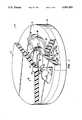
- FIG. 1is a perspective view of a centrifugal rotor constructed in accordance with the principles of the present invention, with portions broken away.
- FIGS. 1A and 1Billustrate alternate geometries for a separation chamber of the type employed in a centrifugal rotor constructed in accordance with the principles of the present invention.
- FIG. 2is a top plan view of the centrifugal rotor of FIG. 1.
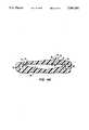
- FIG. 3is a vertical cross-sectional view of the rotor of FIGS. 1 and 2, taken along line 3--3 in FIG. 2.
- FIG. 4is a vertical cross-sectional view of the rotor of FIGS. 1 and 2, taken along line 4--4 in FIG. 2.
- FIG. 4Ais a cross-sectional view similar to that shown in FIG. 4, illustrating an alternative collection chamber geometry.
- FIG. 5is a horizontal cross-sectional view of the rotor of FIGS. 1-3, taken along line 5--5 in FIG. 3.
- FIG. 6is a horizontal cross-sectional view of the rotor of FIGS. 1-3, taken along line 6--6 in FIGS. 3 and 4.
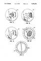
- FIGS. 7-11illustrate the method of the present invention utilizing the centrifugal rotor of FIG. 1.
- FIG. 12illustrates an alternate embodiment of the centrifugal rotor of the present invention.
- the present inventionprovides apparatus and methods for separating cellular components from biological fluids, and in particular for separating whole blood into plasma which may then be subjected to a wide variety of analytic procedures.
- the apparatus and methodswill also provide for distribution of the separated plasma into a plurality of test wells within the rotor so that different analytic procedures may be performed without having to transfer aliquots of the plasma from the apparatus.
- the apparatus and methodare able to separate very low volumes of blood, usually as low as about 0.03 cc, frequently as low as about 0.015 cc, and sometimes as low as about 0.005 cc, although the present invention is suitable for separating much larger volumes as well.
- the present inventiondoes not require the use of a displacement medium for effecting the desired separation and distribution, and the apparatus design is very simple with no separate or moving parts required. Of course, it may be desirable in certain circumstances to provide such separate or moving parts, but they are not required in order to achieve the blood separation according to the method of the present invention.
- the apparatusis very easy to manufacture and can be produced at a very low cost, making the apparatus suitable for use as a disposable in testing whole-blood samples.
- the apparatus and methodare able to separate precise volumes of blood without the need to premeasure the amount applied to the apparatus.
- the apparatuscan further provide for automatic combination of the separated plasma with a reagent or diluent and can apportion substantially equal volumes of plasma among the plurality of test wells.
- the apparatusis suitable for use with a variety of conventional analytic measurement devices, such as spectrophotometers and fluorometers, which allow the plasma in the test wells to be individually examined without the need to remove the plasma from the wells.
- the present inventionis particularly suitable for separating cells from blood to produce plasma, it will be useful with a wide variety of other biological fluids, such as urine, sputum, semen, saliva, ocular lens fluid, cerebral fluid, spinal fluid, amniotic fluid, and tissue culture media, as well as food and industrial chemicals, and the like, where it may be desirable to separate cells and other interfering substances prior to analysis or assay.
- biological fluidssuch as urine, sputum, semen, saliva, ocular lens fluid, cerebral fluid, spinal fluid, amniotic fluid, and tissue culture media, as well as food and industrial chemicals, and the like, where it may be desirable to separate cells and other interfering substances prior to analysis or assay.
- the apparatus of the present inventionincludes a centrifugal rotor which is capable of being mounted on a conventional laboratory centrifuge of the type which is commercially available from suppliers, such as Beckman Instruments, Inc., Spinco Division, Fullerton, Calif.; Fisher Scientific, Pittsburgh, Pa.; VWR Scientific, San Francisco, Calif., and the like.
- the centrifugal rotorswill include a receptacle or other coupling device suitable for mounting on a vertical drive shaft within the centrifuge.
- centrifugal rotor of the present inventionmay be adapted to be used with most types of centrifuges which are now available or which may become available in the future.
- the centrifugal rotorcomprises a body structure which maintains a desired geometric pattern or relationship between a plurality of chambers and interconnecting passages, as described in more detail hereinbelow.
- the bodywill be a substantially solid plate with the chambers and passages formed as spaces or voids in an otherwise solid matrix.
- such solid plate structuresmay be formed by laminating a plurality of separately formed layers together into a composite structure where the chambers and passages are generally formed between adjacent layers.
- the individual layersmay be formed by injection molding, machining, and combinations thereof, and will usually be joined together, typically using a suitable adhesive or by ultrasonic welding. The final enclosed volumes are formed when the layers are brought together.
- centrifugal rotorcould also be formed as a plurality of discrete components, such as tubes, vessels, chambers, etc., arranged in a suitable structural framework. Such assemblies, however, are generally more difficult to manufacture and are therefore less desirable than those formed in a substantially solid plate.
- the centrifugal rotormay be formed from a wide variety of materials and may optionally include two or more materials. Usually, the materials will be transparent so that the presence and distribution of blood, plasma, and other reagents, may be observed within the various internal chambers and passages. Also, it is generally required that the test wells formed within the rotor have suitable optical paths formed therethrough so that the contents of the test well may be observed spectrophotometrically, fluorometrically, or by other visual assessment instruments. In the exemplary embodiment described below, the rotor is formed from acrylic resins having the required optical properties, at least in those areas which define the optical paths.
- the apparatus and method of the present inventionare suitable for performing a wide variety of analytic procedures which are beneficially or necessarily performed on blood plasma.
- the analytic procedureswill generally require that the blood plasma be combined with one or more reagents so that some visibly detectable change occurs in the plasma which may be related to measurement of a particular component or characteristic of the plasma.
- the plasmawill undergo a reaction or other change which results in a change in color, fluorescence, luminescence, or the like, which may be measured by conventional spectrophotometers, fluorometers, light detectors, etc.
- immunoassays and other specific binding assaysmay be performed in the test wells.
- such assay proceduresmust be homogeneous and not require a separation step.
- it will be possible to accommodate heterogeneous assay systemsby providing a means to separate blood plasma from the test wells after an immunological reaction step has occurred.
- the rotor 10is in the form of a substantially solid disk including a top layer 12, middle layer 14, and bottom layer 16 laminated together to form a composite structure.
- each of the layers 12, 14, and 16will be composed of the same material, usually a transparent plastic such as an acrylate, but it is possible that the layers will be composed of different materials and that each layer may include two or more different materials forming different portions of the layer.
- the exposed surface of top layer 12will be referred to as the top surface while the exposed surface of the bottom layer 16 will be referred to as the bottom surface.
- a receptacle 18is formed in the bottom surface of layer 16 and is generally aligned with the vertical axis 20 of the rotor, as best observed in FIGS. 3 and 4.
- the receptacle 18is formed to mate with the drive shaft of a conventional centrifuge system, as described previously.
- the top surface 12includes a blood application port 22 and four vent ports 24, 26, 28, and 30.
- the blood application port 22 and vent ports 24, 26, 28, and 30,penetrate the entire thickness of the top layer 12 and, as described in more detail hereinbelow, are aligned with various chambers formed in the middle layer 14 of the rotor 10. These penetrations may conveniently be formed in the top layer 12 by machining, e.g., drilling.
- the upper surface of middle layer 14includes a plurality of chambers and passages formed therein.
- the chambers and passagesmay be formed by machining a disk having generally flat surfaces or may be formed by injection molding of a suitable plastic resin in order to initially form the disk.
- the middle layer 14includes a metering chamber 40 having an inlet segment 42 which is generally aligned with the blood application port 22 in top layer 12.
- the metering chamber 40is connected to an overflow chamber 44 by a connecting passage 46, with the overflow chamber being located radially outward from the metering chamber.
- a vent connector passage 48extends from the radially-outward end of overflow chamber 44, first in a generally annular direction and thereafter in a generally radially-inward direction.
- the distal terminus 50 of passage 46is aligned with vent port 28 in top layer 12 so that the outward radial extremity of overflow chamber 44 will be vented to the atmosphere during use of the rotor 10.
- the depth of metering chamber 40 and overflow chamber 44will be selected to provide for capillary dimensions when the chambers are completed by lamination of the top layer 12.
- the depthwill be in the range from about 0.1 to 1.0 mm, more typically being in the range from about 0.25 to 0.75 mm.
- the depthwill be uniform for both chambers 40 and 46 as well as the connecting passage 46, although it will be possible to vary the depth so long as capillarity is maintained.
- a separation chamber 60is formed in the upper surface of middle layer 14 and is disposed radially outward from the metering chamber 40.
- the separation chamber 60includes a cell trap 62 formed at its radially-outward periphery and a receptacle region 65 formed along its radially-inward perimeter.
- a capillary region 66is formed between the receptacle region 65 and the cell trap 62 in order to inhibit the backflow of cells after they have entered the cell trap 62 as a result of centrifugal separation.
- the receptacle region 65provides a volume which is capable of receiving whole blood or other biological fluid (optionally combined with a diluent or reagent) and which retains the blood plasma or other separated fluid after centrifugation has been completed.
- An axial port 64is conveniently formed as an annular passage which penetrates the entire thickness of middle layer 14 so that separated plasma may flow downward from receptacle region 65 of chamber 60 into a collection chamber 90 formed in bottom layer 16, as described in more detail hereinafter.
- the geometry of the separation chamber 60may be varied considerably, as discussed in more detail in connection with FIGS. 1A and 1B, below.
- the metering chamber 40is connected to the separation chamber 60 by a short capillary passage 70 which terminates in a vertical wall 72 which forms the inner surface of axial port 64. Such termination of passage 70 will, of course, terminate the capillarity which would otherwise draw fluid through the passage.
- the volume of metering chamber 40will vary depending on the desired application, but will usually be selected to be as low as possible to provide a desired amount of plasma to each of the test wells formed in bottom layer 16, as described in more detail hereinafter. Typically, the volume of metering chamber 40 will be in the range from about 0.005 to 0.05 cc, more typically being in the range from about 0.030 to 0.040 cc.
- the volume of overflow chamber 44will generally be larger than that of the metering chamber 40 in order to accommodate excess blood which may be applied through blood application port 42. Generally, the volume of the overflow chamber 44 will be at least twice that of the metering chamber 40, typically being three or more times larger.
- the volume of separation chamber 60will be selected to accommodate the expected volume of plasma and optionally reagent or dilent which can flow from the metering chamber 40 and reagent chamber 80 (as described below).
- the volume of the receptacle region 65will be in the range from about 0.1 cc to 1.0 cc, more typically being in the range from about 0.25 cc to 0.50 cc.
- the volume of the cell trap 62will depend at least in part on the volume of the receptacle region 65. In order to maximize the efficiency of separation, i.e., increase the amount of plasma obtained from a fixed amount of whole blood, it is desirable that the volume of the cell trap 62 be just large enough to accommodate the largest expected volume of cellular material.
- the volume of cell trap 62will then be the expected percentage of the volume of metering chamber 40.
- the volume of cell trap 62will be from about 100% to 200% of the volume of metering chamber 40.
- a reagent chamber 80is also formed in the upper surface of middle layer 14 and connected to the separation chamber 60 through a capillary passage 82.
- the reagent chamber 80will be disposed radially inward from the separation chamber 60 so that flow of reagent or diluent from the reagent chamber to the separation chamber 60 may be effected by spinning the rotor 14, as will be described in more detail hereinafter.
- the capillary passage 80terminates with an open channel in wall 72. In this way, flow of reagent from chamber 80 will not occur in the absence of outward centrifugal force resulting from spinning of the rotor 10.
- a removable seal or barrier in chamber 82or contain the reagent within a pouch or other package, to preserve the reagent and further assure that the reagent will not leak from chamber 80.
- a barrier, seal or packagewill be particularly desirable when the reagent is "prepackaged" into the centrifugal rotor 10 at a central preparation facility and later subjected to shipping, storing, and other handling procedures which might otherwise cause the reagent to degrade or leak.
- the reagent chamber 80may have substantially greater depth than the metering chamber 40 since the ability to provide capillary flow is not necessary. Thus, it is easy to store volumes of reagent which are substantially greater than the volume of blood or plasma which is provided to separation chamber 60 from metering chamber 40.
- a collection chamber 90is formed in the upper surface of bottom layer 16 and is disposed to receive plasma from the axial port 64.
- a plurality of test wells 92is formed about the periphery of the collection chamber 90 and connected by short radial passages 94. Generally, the test wells 92 will be spaced equally about the periphery of layer 16 in order to enhance the equal distribution of plasma to each of the test wells.
- the material above and below each test well 92will usually be optically transparent in order to provide a clear optical path for visual assessment of the plasma in each well. Alternate optical paths through the rotor 10 may also be provided.
- the volume of the test wells 92will usually be relatively low, typically being in the range from about 0.005 cc to 0.015 cc, more usually being in the range from about 0.008 cc to 0.010 cc. It is possible that liquid, dried, or lyophilized reagents may be provided within the individual test wells so that combination occurs with the plasma when it is introduced. Alternatively, the walls or bottom of the test well 92 may be derivatized with various active components, such as antibodies, antigens, receptors, or the like, which are intended to take part in the analytic procedure.
- the central feature of the separation chamber 60is the capillary region 66, which is preferably an annular space having an inner arcuate boundary 200 and an outer arcuate boundary 202.
- the capillarity of region 66is broken at each boundary 200 and 202 as the size of the adjoining regions, i.e., receptacle region 65 and cell trap 62, are increased to break the capillarity.
- fluidwill be unable to flow through the capillary region 66 except when sufficient centrifugal force is applied by centrifugation.
- the shapes of the receptacle region 65 and cell trap 62may vary substantially.
- the receptacle region 65will generally be tapered so that the distance between opposed horizontal surfaces increases in the radially inward direction. Such increasing distance provides the desired capillarity break, as discussed above.
- the tapermay be provided by inclining the lower surface relative to the horizontal plane (FIG. 1), inclining the upper surface relative to the horizontal plane (FIG. 1A), or inclining both surfaces (FIG. 1B).
- the angle between the opposed surfaces of receptacle region 65is not critical, typically being between 0° and 40°, and usually being between 18° and 22°.
- the inner arcuate boundary 200 of the capillary regionis usually formed contiguously with the narrow end of the tapered receptacle region which defines an arcuate aperture.
- the cell trap 62is typically formed as an annular well which penetrates axially downward in the rotor and which is disposed contiguously with the outer arcuate boundary 202 of the annular space of the capillary region 66.
- the cell trap 62may also extend upwardly, as illustrated in FIG. 1B, need not have a true annular shape.
- the geometry of collection chamber 90may be modified to promote mixing of the separated biological fluid, e.g., plasma, with a diluent or reagent combined in separation chamber 60.
- the volume of the collection chamber 90may be increased and a peripheral vertical wall 91 may be provided inside of radial passages 94.
- the radial passage 94will be capillaries which serve to prevent loss of fluid from the test wells 92 after the separation and distribution steps are completed.
- the increased volume of collection chamber 90 and peripheral wall 91both act to increase the retention time of liquid in chamber 90 as the rotor 10 is spun. Such increased retention time allows more thorough mixing prior to distribution.
- downward flow of plasma or other separated fluid through axial port 64may be restricted by surface tension.
- the surface tensioncan be disrupted by abruptly stopping the spinning of the rotor 10 after separation has been achieved. Such cessation of spinning will cause the fluid to wet the wall of the region 65, allowing downflow.
- reagent chamber 80will be filled with reagent to a desired volume. As illustrated, the chamber 80 is entirely filled, but it is also possible that the chamber will be partially filled.
- the reagentmay be loaded into rotor 10 either at a central preparation facility or immediately prior to use by the user. In the later case, the reagent may be filled using a pipette through vent port 24.
- Whole bloodmay be loaded onto the rotor 10 through application port 24 in a volume greater than that which can be accommodated by measuring chamber 40.
- the bloodAs soon as the blood is applied through port 22, it will begin to flow laterally both into the main portion of chamber 40 and through passage 46 into overflow chamber 44 by capillary action. Since the flow area into measuring chamber 40 is substantially larger than that through passage 46, the measuring chamber will quickly fill with blood, with the overflow passing into overflow chamber 44. In this way, the blood applied through port 22 need not be carefully measured prior to application. After a time sufficient for the blood to partition between measuring chamber 40 and overflow chamber 44, the distribution of blood will be as illustrated in FIG. 7 with the capillary portion of chamber 40 being completely filled and overflow chamber 44 being partially filled.
- the rotor 10will be centrifuged or spun at a rate sufficient to cause the blood from chamber 40 and reagent from chamber 80 to flow into separation chamber 60. Additionally, the blood in overflow chamber 44 will flow radially outward, as illustrated.
- the rotor 10will be spun at a rate in the range from about 1500 rpm to 5000 rpm, more usually from about 2500 rpm to 4000 rpm, for a time in the range from about 20 seconds to 5 minutes, more typically being about 1 minute to 3 minutes, so that the cellular components of the blood will flow into trap 66 while the plasma will remain generally in the open portion of separation chamber 60.
- the rotor 10After the separation of plasmas from the cellular components of the whole blood has been completed, spinning of the rotor 10 will be stopped and the separated plasma will flow downward through axial passage 64, as illustrated in FIGS. 9 and 10. The cellular components remain in cell trap 66, and the overflow blood remains in overflow chamber 44 while the plasma has flowed downward into a pool P in collection chamber 90. The plasma may then be distributed substantially equally into the individual test wells 92 by further rotation of the rotor 10, typically at a rate in the range from about 900 rpm to 5000 rpm for a time in the range from about 10 seconds to 1 minute. After the desired distribution has been achieved, the rotor 10 may be removed from the centrifuge and the rotor transferred to an appropriate instrument, such as a spectrophotometer or fluorometer, for testing.
- an appropriate instrumentsuch as a spectrophotometer or fluorometer
- the rotor 100will generally be a laminate structure similar to rotor 10, with only a middle layer 102 being illustrated in FIG. 12.
- the upper layerwill include an application port (not illustrated) which is aligned with an entry chamber 104 formed in the upper surface of layer 102.
- the entry chamber 104is generally aligned with the vertical (spinning) axis of the rotor 100, and a pair of passages 106 and 108 extend radially outward from said entry port.
- Chamber 106serves as the measuring chamber and has a larger cross-sectional area than passage 108 so that it will fill more rapidly.
- Chamber 108serves as the overflow chamber so that it can take up any excess blood which is applied through entry chamber 104.
- a reagent chamber 110is located radially outward from the entry chamber 104 and connects with a non-capillary passage 112, which is connected with the distal end of chamber 106 and extends generally radially outward.
- the rotor 100may be spun to cause both the blood from passage 106 and reagent from chamber 110 to flow outward through passage 112 into a separation chamber 114.
- the cellsgenerally to collect along the radially-outward wall 116 of chamber 114, and further to flow down a spirally-outward path 118 to collect in cell trap 120.
- the separation chamber 114 and cell trap 120are vented through the terminal end 122 of event path 124.
- a drainage port 126formed at the radially-inward periphery of separation chamber 114.
- the bottom floor of chamber 114will be sloped downward in the inward radial direction to promote the drainage of plasma through port 126.
- a collection chamberwill be formed beneath the drainage port 126 in a manner similar to that illustrated in FIGS. 1-6.
- metering chambersmay be provided in order to run simultaneous tests and assays which require different test conditions.
- multiple metering chambersmay be provided to allow combination with different reagents or diluents in isolated separation chambers.
- a single metering chambermay be connected by separate capillary passages to control flow into separate separation chambers. In either case, assays and tests requiring different protocols can be carried out in a single rotor system.
Landscapes
- Health & Medical Sciences (AREA)
- Life Sciences & Earth Sciences (AREA)
- Engineering & Computer Science (AREA)
- Biomedical Technology (AREA)
- Chemical & Material Sciences (AREA)
- Physics & Mathematics (AREA)
- General Health & Medical Sciences (AREA)
- General Physics & Mathematics (AREA)
- Immunology (AREA)
- Pathology (AREA)
- Biochemistry (AREA)
- Hematology (AREA)
- Analytical Chemistry (AREA)
- Ecology (AREA)
- Biophysics (AREA)
- Molecular Biology (AREA)
- Urology & Nephrology (AREA)
- Food Science & Technology (AREA)
- Medicinal Chemistry (AREA)
- Investigating Or Analysing Biological Materials (AREA)
- Centrifugal Separators (AREA)
Abstract
Description
Claims (29)
Priority Applications (13)
| Application Number | Priority Date | Filing Date | Title |
|---|---|---|---|
| US07/532,524US5061381A (en) | 1990-06-04 | 1990-06-04 | Apparatus and method for separating cells from biological fluids |
| US07/678,824US5122284A (en) | 1990-06-04 | 1991-04-01 | Apparatus and method for optically analyzing biological fluids |
| CA002082827ACA2082827C (en) | 1990-06-04 | 1991-05-31 | Analytical rotors and methods for analysis of biological fluids |
| EP19910910787EP0532591A4 (en) | 1990-06-04 | 1991-05-31 | Analytical rotors and methods for analysis of biological fluids |
| JP3510484AJP3061414B2 (en) | 1990-06-04 | 1991-05-31 | Rotating device for analysis and method for analyzing biological fluid |
| DE1991630986DE69130986T2 (en) | 1990-06-04 | 1991-05-31 | Rotors for analysis and methods for the analysis of biological fluids |
| EP94104814AEP0608006B1 (en) | 1990-06-04 | 1991-05-31 | Analytical rotors and methods for analysis of biological fluids |
| AU80838/91AAU8083891A (en) | 1990-06-04 | 1991-05-31 | Analytical rotors and methods for analysis of biological fluids |
| PCT/US1991/003840WO1991018656A1 (en) | 1990-06-04 | 1991-05-31 | Analytical rotors and methods for analysis of biological fluids |
| CA002347669ACA2347669C (en) | 1990-06-04 | 1991-05-31 | Analytical rotors and methods for analysis of biological fluids |
| CA002346975ACA2346975C (en) | 1990-06-04 | 1991-05-31 | Analytical rotors and methods for analysis of biological fluids |
| CA002346974ACA2346974C (en) | 1990-06-04 | 1991-05-31 | Analytical rotors and methods for analysis of biological fluids |
| US07/783,041US5242606A (en) | 1990-06-04 | 1991-10-29 | Sample metering port for analytical rotor having overflow chamber |
Applications Claiming Priority (1)
| Application Number | Priority Date | Filing Date | Title |
|---|---|---|---|
| US07/532,524US5061381A (en) | 1990-06-04 | 1990-06-04 | Apparatus and method for separating cells from biological fluids |
Related Child Applications (2)
| Application Number | Title | Priority Date | Filing Date |
|---|---|---|---|
| US07/678,824Continuation-In-PartUS5122284A (en) | 1990-06-04 | 1991-04-01 | Apparatus and method for optically analyzing biological fluids |
| US07/783,041Continuation-In-PartUS5242606A (en) | 1990-06-04 | 1991-10-29 | Sample metering port for analytical rotor having overflow chamber |
Publications (1)
| Publication Number | Publication Date |
|---|---|
| US5061381Atrue US5061381A (en) | 1991-10-29 |
Family
ID=24122158
Family Applications (1)
| Application Number | Title | Priority Date | Filing Date |
|---|---|---|---|
| US07/532,524Expired - LifetimeUS5061381A (en) | 1990-06-04 | 1990-06-04 | Apparatus and method for separating cells from biological fluids |
Country Status (1)
| Country | Link |
|---|---|
| US (1) | US5061381A (en) |
Cited By (153)
| Publication number | Priority date | Publication date | Assignee | Title |
|---|---|---|---|---|
| WO1993008893A1 (en)* | 1991-10-29 | 1993-05-13 | Abaxis, Inc. | Sample metering port for analytical rotor |
| WO1993016391A1 (en)* | 1992-02-11 | 1993-08-19 | Abaxis, Inc. | Reagent container for analytical rotor |
| WO1993019827A1 (en)* | 1992-04-02 | 1993-10-14 | Abaxis, Inc. | Analytical rotor with dye mixing chamber |
| WO1993022673A1 (en)* | 1992-05-01 | 1993-11-11 | Du Pont Canada Inc. | Flow restrictor-separation device |
| WO1995006870A1 (en)* | 1993-09-01 | 1995-03-09 | Abaxis, Inc. | Simplified inlet channels |
| WO1995006508A1 (en)* | 1993-09-01 | 1995-03-09 | Abaxis, Inc. | Simultaneous cuvette filling with means to isolate cuvettes |
| US5478750A (en)* | 1993-03-31 | 1995-12-26 | Abaxis, Inc. | Methods for photometric analysis |
| WO1996016715A1 (en)* | 1994-12-02 | 1996-06-06 | E.R. Squibb And Sons, Inc. | Centrifuge with annular filter |
| WO1996016714A1 (en)* | 1994-12-02 | 1996-06-06 | Bristol-Myers Squibb Company | Method and device for separating fibrin monomer from blood plasma |
| WO1996016713A1 (en)* | 1994-12-02 | 1996-06-06 | E.R. Squibb And Sons, Inc. | Centrifuge reagent delivery system |
| EP0641389A4 (en)* | 1991-08-19 | 1996-11-20 | Abay Sa | Reagent compositions for analytical testing. |
| US5610074A (en)* | 1993-02-24 | 1997-03-11 | Beritashvili; David R. | Centrifugal method and apparatus for isolating a substance from a mixture of substances in a sample liquid |
| US5631166A (en)* | 1995-03-21 | 1997-05-20 | Jewell; Charles R. | Specimen disk for blood analyses |
| US5750074A (en)* | 1995-01-23 | 1998-05-12 | Beckman Instruments, Inc. | Reagent segment |
| US5776563A (en)* | 1991-08-19 | 1998-07-07 | Abaxis, Inc. | Dried chemical compositions |
| US5858253A (en)* | 1993-11-19 | 1999-01-12 | Bristol-Myers Squibb Company | Blood separation process |
| US5916522A (en)* | 1997-08-07 | 1999-06-29 | Careside, Inc. | Electrochemical analytical cartridge |
| US5919711A (en)* | 1997-08-07 | 1999-07-06 | Careside, Inc. | Analytical cartridge |
| US6002475A (en)* | 1998-01-28 | 1999-12-14 | Careside, Inc. | Spectrophotometric analytical cartridge |
| US6030581A (en)* | 1997-02-28 | 2000-02-29 | Burstein Laboratories | Laboratory in a disk |
| US6143247A (en)* | 1996-12-20 | 2000-11-07 | Gamera Bioscience Inc. | Affinity binding-based system for detecting particulates in a fluid |
| US6143248A (en)* | 1996-08-12 | 2000-11-07 | Gamera Bioscience Corp. | Capillary microvalve |
| US6153148A (en)* | 1998-06-15 | 2000-11-28 | Becton, Dickinson And Company | Centrifugal hematology disposable |
| US6176962B1 (en) | 1990-02-28 | 2001-01-23 | Aclara Biosciences, Inc. | Methods for fabricating enclosed microchannel structures |
| US6302134B1 (en) | 1997-05-23 | 2001-10-16 | Tecan Boston | Device and method for using centripetal acceleration to device fluid movement on a microfluidics system |
| US6319469B1 (en)* | 1995-12-18 | 2001-11-20 | Silicon Valley Bank | Devices and methods for using centripetal acceleration to drive fluid movement in a microfluidics system |
| US6348176B1 (en) | 1999-02-11 | 2002-02-19 | Careside, Inc. | Cartridge-based analytical instrument using centrifugal force/pressure for metering/transport of fluids |
| US6391264B2 (en) | 1999-02-11 | 2002-05-21 | Careside, Inc. | Cartridge-based analytical instrument with rotor balance and cartridge lock/eject system |
| US20020076354A1 (en)* | 2000-12-01 | 2002-06-20 | Cohen David Samuel | Apparatus and methods for separating components of particulate suspension |
| US20020076805A1 (en)* | 2000-12-15 | 2002-06-20 | Jorma Virtanen | Detection system for disk-based laboratory and improved optical bio-disc including same |
| US20020098528A1 (en)* | 2000-11-17 | 2002-07-25 | Gordon John F. | Methods and apparatus for blood typing with optical bio-disc |
| US20020097632A1 (en)* | 2000-05-15 | 2002-07-25 | Kellogg Gregory J. | Bidirectional flow centrifugal microfluidic devices |
| WO2002072264A1 (en)* | 2001-03-09 | 2002-09-19 | Biomicro Systems, Inc. | Method and system for microfluidic interfacing to arrays |
| US20020196435A1 (en)* | 2000-11-22 | 2002-12-26 | Cohen David Samuel | Apparatus and methods for separating agglutinants and disperse particles |
| US6511814B1 (en) | 1999-03-26 | 2003-01-28 | Idexx Laboratories, Inc. | Method and device for detecting analytes in fluids |
| US6531095B2 (en) | 1999-02-11 | 2003-03-11 | Careside, Inc. | Cartridge-based analytical instrument with optical detector |
| US6551842B1 (en) | 1999-03-26 | 2003-04-22 | Idexx Laboratories, Inc. | Method and device for detecting analytes in fluids |
| US20030096434A1 (en)* | 2001-07-12 | 2003-05-22 | Krutzik Siegfried Richard | Multi-purpose optical analysis optical bio-disc for conducting assays and various reporting agents for use therewith |
| US20030104486A1 (en)* | 2000-11-16 | 2003-06-05 | Selvan Gowri Pyapali | Methods and apparatus for detecting and quantifying lymphocytes with optical biodiscs |
| US20030113925A1 (en)* | 2001-09-07 | 2003-06-19 | Gordon John Francis | Nuclear morphology based identification and quantification of white blood cell types using optical bio-disc systems |
| US20030129665A1 (en)* | 2001-08-30 | 2003-07-10 | Selvan Gowri Pyapali | Methods for qualitative and quantitative analysis of cells and related optical bio-disc systems |
| US20030143637A1 (en)* | 2001-08-31 | 2003-07-31 | Selvan Gowri Pyapali | Capture layer assemblies for cellular assays including related optical analysis discs and methods |
| US6602719B1 (en) | 1999-03-26 | 2003-08-05 | Idexx Laboratories, Inc. | Method and device for detecting analytes in fluids |
| US20030185713A1 (en)* | 2002-03-29 | 2003-10-02 | Leslie Leonard | Capillary flow for a heterogenous assay in a micro-channel environment |
| US6632399B1 (en) | 1998-05-22 | 2003-10-14 | Tecan Trading Ag | Devices and methods for using centripetal acceleration to drive fluid movement in a microfluidics system for performing biological fluid assays |
| US20030219713A1 (en)* | 2001-11-20 | 2003-11-27 | Valencia Ramoncito Magpantay | Optical bio-discs and fluidic circuits for analysis of cells and methods relating thereto |
| US20030224457A1 (en)* | 2000-11-17 | 2003-12-04 | Hurt Susan Newcomb | Methods and apparatus for blood typing with optical bio-discs |
| US20030232403A1 (en)* | 1999-06-18 | 2003-12-18 | Kellogg Gregory L. | Devices and methods for the performance of miniaturized homogeneous assays |
| US20030230383A1 (en)* | 2001-07-24 | 2003-12-18 | Glenn Sasaki | Method and apparatus for bonded fluidic circuit for optical bio-disc |
| US20040018116A1 (en)* | 2002-07-26 | 2004-01-29 | Desmond Sean M. | Microfluidic size-exclusion devices, systems, and methods |
| US6692701B2 (en)* | 2001-02-01 | 2004-02-17 | V & P Scientific, Inc. | Microarrayer |
| US20040038647A1 (en)* | 1993-12-20 | 2004-02-26 | Intermec Technologies Corporation | Local area network having multiple channel wireless access |
| WO2003043403A3 (en)* | 2001-11-19 | 2004-02-26 | Burstein Technologies Inc | Methods and apparatus for blood typing with optical bio-discs |
| US6709869B2 (en) | 1995-12-18 | 2004-03-23 | Tecan Trading Ag | Devices and methods for using centripetal acceleration to drive fluid movement in a microfluidics system |
| US20040078145A1 (en)* | 2002-10-18 | 2004-04-22 | Ostoich Vladimir E. | Systems and methods for the detection of short and long samples |
| US6736768B2 (en) | 2000-11-02 | 2004-05-18 | Gambro Inc | Fluid separation devices, systems and/or methods using a fluid pressure driven and/or balanced approach |
| US6752961B2 (en) | 1993-09-01 | 2004-06-22 | Abaxis, Inc. | Modified siphons for improving metering precision |
| US20040241381A1 (en)* | 2002-01-31 | 2004-12-02 | Chen Yihfar | Microfluidic structures with circumferential grooves for bonding adhesives and related optical analysis discs |
| US20050003459A1 (en)* | 2002-01-30 | 2005-01-06 | Krutzik Siegfried Richard | Multi-purpose optical analysis disc for conducting assays and related methods for attaching capture agents |
| US20050023765A1 (en)* | 2002-01-31 | 2005-02-03 | Coombs James Howard | Bio-safety features for optical analysis disc and disc system including same |
| US20050037484A1 (en)* | 2003-04-23 | 2005-02-17 | Norbert Staimer | Optical bio-discs including spiral fluidic circuits for performing assays |
| US20050047968A1 (en)* | 2003-06-19 | 2005-03-03 | Horacio Kido | Fluidic circuits for sample preparation including bio-discs and methods relating thereto |
| WO2005009581A3 (en)* | 2003-07-15 | 2005-03-24 | Nagaoka Kk | Methods and apparatus for blood separation and analysis using membranes on an optical bio-disc |
| US20050084422A1 (en)* | 2003-06-19 | 2005-04-21 | Horacio Kido | Fluidic circuits for sample preparation including bio-discs and methods relating thereto |
| US20050176059A1 (en)* | 2002-01-31 | 2005-08-11 | Pal Andrew A. | Bio-safe dispenser and optical analysis disc assembly |
| US20050221048A1 (en)* | 2002-01-31 | 2005-10-06 | James Rodney Norton | Manufacturing processes for making optical analysis discs including successive patterning operations and optical discs thereby manufactured |
| US20050230328A1 (en)* | 2004-04-16 | 2005-10-20 | Kyungyoon Min | Methods for determining flow rates of biological fluids |
| US20060013741A1 (en)* | 2004-07-15 | 2006-01-19 | Applera Corporation | Fluid processing device |
| US20060035271A1 (en)* | 2001-01-31 | 2006-02-16 | Mcentee John F | Reaction chamber roll pump |
| US7033747B2 (en) | 2001-04-11 | 2006-04-25 | Nagaoka & Co., Ltd | Multi-parameter assays including analysis discs and methods relating thereto |
| US20060133958A1 (en)* | 2004-12-22 | 2006-06-22 | Wen-Pin Hsieh | Fluid analytical devices |
| US20060228793A1 (en)* | 2005-02-05 | 2006-10-12 | Cho Yoon-Kyoung | Microsystem for separating serum from blood |
| US20060263265A1 (en)* | 2005-05-23 | 2006-11-23 | Der-Ren Kang | Blood micro-separator |
| US20070003437A1 (en)* | 2005-01-24 | 2007-01-04 | Matsushita Electric Industrial Co., Ltd. | Liquid delivery apparatus and liquid delivery method |
| US7166231B2 (en) | 1999-09-03 | 2007-01-23 | Baxter International Inc. | Red blood cell separation method |
| US20070041874A1 (en)* | 2003-05-06 | 2007-02-22 | Sivaprasad Sukavaneshvar | Systems and methods for measuring fluid properties |
| US7211037B2 (en) | 2002-03-04 | 2007-05-01 | Therakos, Inc. | Apparatus for the continuous separation of biological fluids into components and method of using same |
| US20070166721A1 (en)* | 2003-06-27 | 2007-07-19 | Phan Brigitte C | Fluidic circuits, methods and apparatus for use of whole blood samples in colorimetric assays |
| US7297272B2 (en) | 2002-10-24 | 2007-11-20 | Fenwal, Inc. | Separation apparatus and method |
| US20070274863A1 (en)* | 2003-07-25 | 2007-11-29 | Horacio Kido | Fluidic circuits for sample preparation including bio-discs and methods relating thereto |
| US20080035579A1 (en)* | 2006-08-11 | 2008-02-14 | Samsung Electronics Co., Ltd. | Centrifugal magnetic position control device, disk-shaped micro fluidic system including the same, and method of operating the compact disk-shaped micro fluidic system |
| KR100841355B1 (en) | 2006-04-04 | 2008-07-01 | 주식회사 올메디쿠스 | Biosensor chip with non-powered blood separation means |
| US20080171400A1 (en)* | 2006-08-30 | 2008-07-17 | Samsung Electronics Co., Ltd | Magnetic microparticle-packing unit, microfluidic device including the same, and immunoassay method using the microfluidic device |
| US20080225295A1 (en)* | 2007-03-12 | 2008-09-18 | Resolved Technologies, Inc. | Device for multiple tests from a single sample |
| US20080237151A1 (en)* | 2007-04-02 | 2008-10-02 | Samsung Electronics Co., Ltd. | Centrifugal force-based microfluidic device and microfluidic system including the same |
| US20080280365A1 (en)* | 2005-10-07 | 2008-11-13 | Albert-Ludwigs-Universiitat Freiburg | Apparatus and Method for Determining the Volume Fractions of the Phases in a Suspension |
| US7476209B2 (en) | 2004-12-21 | 2009-01-13 | Therakos, Inc. | Method and apparatus for collecting a blood component and performing a photopheresis treatment |
| US7479123B2 (en) | 2002-03-04 | 2009-01-20 | Therakos, Inc. | Method for collecting a desired blood component and performing a photopheresis treatment |
| EP2010326A4 (en)* | 2006-03-30 | 2009-05-06 | Applied Biosystems | High density plate filler |
| US20090114608A1 (en)* | 2007-11-02 | 2009-05-07 | Industrial Technology Research Institute | Fluid analytical device |
| US20090191643A1 (en)* | 2006-09-27 | 2009-07-30 | Roche Diagnostics Operations, Inc. | Rotatable Test Element |
| WO2009079051A3 (en)* | 2007-09-19 | 2009-08-27 | Nanogen, Inc. | Counter-centrifugal force device |
| US20090225316A1 (en)* | 2008-03-05 | 2009-09-10 | Sivaprasad Sukavaneshvar | Systems for Measuring Properties of a Physiological Fluid Suspension |
| US20090238724A1 (en)* | 2005-11-02 | 2009-09-24 | Matsushita Electric Industrial Co., Ltd. | Disc for analyzing sample |
| US20100050751A1 (en)* | 2008-09-02 | 2010-03-04 | Samsung Electronics Co., Ltd. | Microfluidic device and method of loading sample into the microfluidic device |
| WO2009130694A3 (en)* | 2008-04-21 | 2010-03-18 | Cell Kinetics Ltd. | Flat cell carriers with cell traps |
| US20100184228A1 (en)* | 2007-07-27 | 2010-07-22 | Panasonic Corporation | Device for analysis and analyzing apparatus and method using the device |
| US20100240142A1 (en)* | 2007-11-08 | 2010-09-23 | Panasonic Corporation | Analyzing device and analyzing method using same |
| US20100255589A1 (en)* | 2007-10-30 | 2010-10-07 | Panasonic Corporation | Analyzing device, analyzing apparatus using the device, and analyzing method |
| EP1483052B1 (en)* | 2001-08-28 | 2010-12-22 | Gyros Patent Ab | Retaining microfluidic microcavity and other microfluidic structures |
| US20110053202A1 (en)* | 2009-08-25 | 2011-03-03 | Industrial Technology Research Institute | Analytical system, analytical method and flow-path structure |
| US7914753B2 (en) | 2008-05-28 | 2011-03-29 | Industrial Technology Research Institute | Analytical system, and analytical method and flow structure thereof |
| US20110185827A1 (en)* | 2008-07-29 | 2011-08-04 | Sharp Kabushiki Kaisha | Microdevice, microchip apparatus and analysis method utilizing the same |
| US20110195502A1 (en)* | 2010-02-05 | 2011-08-11 | Medi Medical Engineering Corp. | Centrifugal rotor and method for using the same for delivering biological sample |
| US8075468B2 (en) | 2008-02-27 | 2011-12-13 | Fenwal, Inc. | Systems and methods for mid-processing calculation of blood composition |
| CN101450336B (en)* | 2007-12-06 | 2012-02-08 | 财团法人工业技术研究院 | Fluid separation device and fluid separation method thereof |
| WO2012055707A1 (en)* | 2010-10-28 | 2012-05-03 | Roche Diagnostics Gmbh | Microfluidic test carrier for dividing a liquid quantity into subquantities |
| WO2013044420A1 (en)* | 2011-09-30 | 2013-04-04 | 保生国际生医股份有限公司 | Centrifugal rotary disk |
| US8580560B1 (en) | 2012-12-14 | 2013-11-12 | Scientific Plastic Products, Inc. | Cap with filter and transfer apparatus |
| EP2664381A1 (en)* | 2012-05-18 | 2013-11-20 | Lite-On It Corporation | Analysis cartridge |
| CN103424356A (en)* | 2012-05-21 | 2013-12-04 | 建兴电子科技股份有限公司 | Analysis cassette and analysis system thereof |
| US8685258B2 (en) | 2008-02-27 | 2014-04-01 | Fenwal, Inc. | Systems and methods for conveying multiple blood components to a recipient |
| US8703070B1 (en) | 2012-04-24 | 2014-04-22 | Industrial Technology Research Institute | Apparatus for immunoassay |
| US20150093305A1 (en)* | 2013-09-27 | 2015-04-02 | Robert Bosch Gmbh | Device for handling fluids |
| EP2942104A1 (en) | 2014-05-08 | 2015-11-11 | Radisens Diagnostics Ltd. | Sample applicator for point of care device |
| US9221051B2 (en) | 2010-10-29 | 2015-12-29 | Roche Diagnostics Operations, Inc. | Microfluidic element for analysis of a sample liquid |
| US9261462B2 (en) | 2011-12-12 | 2016-02-16 | Step Ahead Innovations, Inc. | Monitoring of photo-aging of light-based chemical indicators using illumination-brightness differential scheme |
| CN105431726A (en)* | 2013-06-25 | 2016-03-23 | 华盛顿大学商业中心 | Self-digitization of sample volumes |
| EP2917362A4 (en)* | 2012-11-07 | 2016-07-13 | Sandstone Diagnostics Inc | METHODS AND DEVICES FOR SAMPLE PROCESSING AND CELL NUMBERING |
| EP2524234A4 (en)* | 2010-01-15 | 2016-07-20 | Samsung Electronics Co Ltd | SAMPLE ANALYSIS APPARATUS |
| US20160320276A9 (en)* | 2012-11-07 | 2016-11-03 | Sandstone Diagnostics, Inc. | Methods and Devices for Processing Samples and Counting Cells |
| WO2017024163A1 (en) | 2015-08-04 | 2017-02-09 | Abaxis, Inc. | Signal amplification in solution-based plasmonic specific-binding partner assays |
| US20170095812A1 (en)* | 2014-06-06 | 2017-04-06 | Roche Diagnostics Operations, Inc. | Rotatable cartridge with a metering chamber for analyzing a biological sample |
| US20170095813A1 (en)* | 2014-06-06 | 2017-04-06 | Roche Diagnostics Operations, Inc. | Rotatable cartridge for analyzing a biological sample |
| US20170095814A1 (en)* | 2014-06-16 | 2017-04-06 | Roche Diagnostics Operations, Inc. | Cartridge with a rotatable lid |
| US9784686B2 (en) | 2013-06-19 | 2017-10-10 | Step Ahead Innovations, Inc. | Aquatic environment water parameter testing systems and methods |
| US9962699B2 (en) | 2014-06-06 | 2018-05-08 | Roche Diagnostics Operations, Inc. | Rotatable cartridge for processing and analyzing a biological sample |
| CN108469367A (en)* | 2018-05-11 | 2018-08-31 | 石家庄禾柏生物技术股份有限公司 | A kind of centrifugal plasma separation CD |
| US20180361376A1 (en)* | 2013-03-14 | 2018-12-20 | Gen-Probe Incorporated | Reagent well having a capillary insert |
| USD837998S1 (en) | 2017-05-19 | 2019-01-08 | Sandstone Diagnostics, Inc | Centrifuge cartridge |
| US10281465B2 (en) | 2011-11-21 | 2019-05-07 | Abaxis, Inc. | Signal amplification in lateral flow and related immunoassays |
| US10376877B2 (en) | 2013-02-07 | 2019-08-13 | Sandstone Diagnostics, Inc. | Automated sample processing, fluid distribution, and sedimentation assay |
| US10421070B2 (en) | 2008-08-15 | 2019-09-24 | University Of Washington | Method and apparatus for the discretization and manipulation of sample volumes |
| US10488409B2 (en) | 2014-08-13 | 2019-11-26 | Abaxis, Inc. | Signal amplification in plasmonic specific-binding partner assays |
| US10533994B2 (en) | 2006-03-24 | 2020-01-14 | Theranos Ip Company, Llc | Systems and methods of sample processing and fluid control in a fluidic system |
| US10557786B2 (en) | 2011-01-21 | 2020-02-11 | Theranos Ip Company, Llc | Systems and methods for sample use maximization |
| US10634667B2 (en) | 2007-10-02 | 2020-04-28 | Theranos Ip Company, Llc | Modular point-of-care devices, systems, and uses thereof |
| US10717787B1 (en) | 2019-04-03 | 2020-07-21 | Ark Diagnostics, Inc. | Antibodies to symmetrically dimethylated arginine analytes and use thereof |
| US10761030B2 (en) | 2005-05-09 | 2020-09-01 | Labrador Diagnostics Llc | System and methods for analyte detection |
| US10794925B2 (en) | 2015-07-07 | 2020-10-06 | University Of Washington | Systems, methods, and devices for self-digitization of samples |
| US10919039B2 (en) | 2016-06-27 | 2021-02-16 | Abaxis, Inc. | Devices with modified conduits |
| US11094050B2 (en) | 2018-08-24 | 2021-08-17 | Zoetis Services Llc | Systems and methods for inspecting a microfluidic rotor device |
| US11139084B2 (en) | 2009-10-19 | 2021-10-05 | Labrador Diagnostics Llc | Integrated health data capture and analysis system |
| US11162947B2 (en) | 2006-05-10 | 2021-11-02 | Labrador Diagnostics Llc | Real-time detection of influenza virus |
| US11215610B2 (en) | 2006-10-13 | 2022-01-04 | Labrador Diagnostics Llc | Reducing optical interference in a fluidic device |
| US11287421B2 (en) | 2006-03-24 | 2022-03-29 | Labrador Diagnostics Llc | Systems and methods of sample processing and fluid control in a fluidic system |
| US11370177B2 (en) | 2018-08-24 | 2022-06-28 | Zoetis Services Llc | Systems and methods for manufacturing a microfluidic rotor device |
| US11369958B2 (en) | 2018-08-24 | 2022-06-28 | Zoetis Services Llc | Microfluidic rotor device |
| USD966460S1 (en) | 2017-01-10 | 2022-10-11 | Scientific Plastic Products, Inc. | Filter cap |
| US11628452B2 (en) | 2018-08-24 | 2023-04-18 | Zoetis Services Llc | Microfluidic rotor device |
| US11754554B2 (en) | 2007-08-06 | 2023-09-12 | Labrador Diagnostics Llc | Systems and methods of fluidic sample processing |
| US11977072B2 (en) | 2017-01-30 | 2024-05-07 | Zoetis Services Llc | Solution-based plasmonic specific-binding partner assays using metallic nanostructures |
| US12290810B2 (en) | 2018-08-24 | 2025-05-06 | Zoetis Services Llc | Microfluidic rotor device |
Citations (18)
| Publication number | Priority date | Publication date | Assignee | Title |
|---|---|---|---|---|
| US2885145A (en)* | 1956-10-19 | 1959-05-05 | Bo Nyman Abn Aktiebolag | Centrifuges |
| US3241752A (en)* | 1964-01-02 | 1966-03-22 | Monsanto Co | Double-sector centrifugation cells |
| US3707354A (en)* | 1970-06-16 | 1972-12-26 | Harold S Goodman | Means for mixing and centrifugation |
| US3901658A (en)* | 1974-07-30 | 1975-08-26 | Us Energy | Whole blood analysis rotor assembly having removable cellular sedimentation bowl |
| EP0160282A2 (en)* | 1984-05-03 | 1985-11-06 | Abbott Laboratories | Processor card for centrifuge |
| EP0195321A2 (en)* | 1985-03-19 | 1986-09-24 | Abbott Laboratories | Automatic centrifugal balancing mechanism |
| US4632908A (en)* | 1984-05-03 | 1986-12-30 | Abbott Laboratories | Heating system for rotating members |
| FR2589240A1 (en)* | 1985-10-29 | 1987-04-30 | Kis Photo Ind | Single-parameter analysis bar |
| EP0226518A2 (en)* | 1985-10-29 | 1987-06-24 | KIS PHOTO INDUSTRIE (société anonyme) | Centrifugal device for analysing boxes |
| EP0251946A1 (en)* | 1986-06-26 | 1988-01-07 | KIS PHOTO INDUSTRIE S.a.r.l. | Liquid sample analysing device |
| EP0262060A2 (en)* | 1986-09-25 | 1988-03-30 | KIS PHOTO INDUSTRIE S.a.r.l. | Centrifugal arrangement for carrying out analyses |
| US4740472A (en)* | 1985-08-05 | 1988-04-26 | The United States Of America As Represented By The United States Department Of Energy | Method and apparatus for automated processing and aliquoting of whole blood samples for analysis in a centrifugal fast analyzer |
| US4776832A (en)* | 1985-03-21 | 1988-10-11 | Abbott Laboratories | Centrifuge having multiple induction motors for rotating objects about a second axis |
| US4788154A (en)* | 1985-12-20 | 1988-11-29 | Jean Guigan | Method and apparatus for obtaining and delivering a predetermined quantity of plasma from a blood sample for analysis purposes |
| US4798579A (en)* | 1987-10-30 | 1989-01-17 | Beckman Instruments, Inc. | Rotor for centrifuge |
| US4814282A (en)* | 1984-05-03 | 1989-03-21 | Abbott Laboratories | Centrifuge for two-dimensional centrifugation |
| US4835106A (en)* | 1987-07-17 | 1989-05-30 | Martin Marietta Energy Systems, Inc. | Rotor for processing liquids using movable capillary tubes |
| US4847205A (en)* | 1987-04-08 | 1989-07-11 | Martin Marietta Energy Systems, Inc. | Device and method for automated separation of a sample of whole blood into aliquots |
- 1990
- 1990-06-04USUS07/532,524patent/US5061381A/ennot_activeExpired - Lifetime
Patent Citations (18)
| Publication number | Priority date | Publication date | Assignee | Title |
|---|---|---|---|---|
| US2885145A (en)* | 1956-10-19 | 1959-05-05 | Bo Nyman Abn Aktiebolag | Centrifuges |
| US3241752A (en)* | 1964-01-02 | 1966-03-22 | Monsanto Co | Double-sector centrifugation cells |
| US3707354A (en)* | 1970-06-16 | 1972-12-26 | Harold S Goodman | Means for mixing and centrifugation |
| US3901658A (en)* | 1974-07-30 | 1975-08-26 | Us Energy | Whole blood analysis rotor assembly having removable cellular sedimentation bowl |
| EP0160282A2 (en)* | 1984-05-03 | 1985-11-06 | Abbott Laboratories | Processor card for centrifuge |
| US4632908A (en)* | 1984-05-03 | 1986-12-30 | Abbott Laboratories | Heating system for rotating members |
| US4814282A (en)* | 1984-05-03 | 1989-03-21 | Abbott Laboratories | Centrifuge for two-dimensional centrifugation |
| EP0195321A2 (en)* | 1985-03-19 | 1986-09-24 | Abbott Laboratories | Automatic centrifugal balancing mechanism |
| US4776832A (en)* | 1985-03-21 | 1988-10-11 | Abbott Laboratories | Centrifuge having multiple induction motors for rotating objects about a second axis |
| US4740472A (en)* | 1985-08-05 | 1988-04-26 | The United States Of America As Represented By The United States Department Of Energy | Method and apparatus for automated processing and aliquoting of whole blood samples for analysis in a centrifugal fast analyzer |
| EP0226518A2 (en)* | 1985-10-29 | 1987-06-24 | KIS PHOTO INDUSTRIE (société anonyme) | Centrifugal device for analysing boxes |
| FR2589240A1 (en)* | 1985-10-29 | 1987-04-30 | Kis Photo Ind | Single-parameter analysis bar |
| US4788154A (en)* | 1985-12-20 | 1988-11-29 | Jean Guigan | Method and apparatus for obtaining and delivering a predetermined quantity of plasma from a blood sample for analysis purposes |
| EP0251946A1 (en)* | 1986-06-26 | 1988-01-07 | KIS PHOTO INDUSTRIE S.a.r.l. | Liquid sample analysing device |
| EP0262060A2 (en)* | 1986-09-25 | 1988-03-30 | KIS PHOTO INDUSTRIE S.a.r.l. | Centrifugal arrangement for carrying out analyses |
| US4847205A (en)* | 1987-04-08 | 1989-07-11 | Martin Marietta Energy Systems, Inc. | Device and method for automated separation of a sample of whole blood into aliquots |
| US4835106A (en)* | 1987-07-17 | 1989-05-30 | Martin Marietta Energy Systems, Inc. | Rotor for processing liquids using movable capillary tubes |
| US4798579A (en)* | 1987-10-30 | 1989-01-17 | Beckman Instruments, Inc. | Rotor for centrifuge |
Non-Patent Citations (2)
| Title |
|---|
| Analyse Biologique, Clinical Biology, Satelit 900, 6 pages.* |
| Truchaud et al. (1987), Clinical Chemistry 33:1560.* |
Cited By (307)
| Publication number | Priority date | Publication date | Assignee | Title |
|---|---|---|---|---|
| US6176962B1 (en) | 1990-02-28 | 2001-01-23 | Aclara Biosciences, Inc. | Methods for fabricating enclosed microchannel structures |
| US5242606A (en)* | 1990-06-04 | 1993-09-07 | Abaxis, Incorporated | Sample metering port for analytical rotor having overflow chamber |
| EP0641389A4 (en)* | 1991-08-19 | 1996-11-20 | Abay Sa | Reagent compositions for analytical testing. |
| US6251684B1 (en) | 1991-08-19 | 2001-06-26 | Abaxis, Inc. | Dried chemical compositions |
| US5776563A (en)* | 1991-08-19 | 1998-07-07 | Abaxis, Inc. | Dried chemical compositions |
| US5998031A (en)* | 1991-08-19 | 1999-12-07 | Abaxis, Inc. | Dried chemical compositions |
| WO1993008893A1 (en)* | 1991-10-29 | 1993-05-13 | Abaxis, Inc. | Sample metering port for analytical rotor |
| JPH07503794A (en)* | 1992-02-11 | 1995-04-20 | アバクシス,インコーポレイテッド | Reagent containers for analytical rotors |
| US5304348A (en)* | 1992-02-11 | 1994-04-19 | Abaxis, Inc. | Reagent container for analytical rotor |
| JP3361097B2 (en) | 1992-02-11 | 2003-01-07 | アバクシス,インコーポレイテッド | Reagent containers for analytical rotors |
| WO1993016391A1 (en)* | 1992-02-11 | 1993-08-19 | Abaxis, Inc. | Reagent container for analytical rotor |
| US5472603A (en)* | 1992-04-02 | 1995-12-05 | Abaxis, Inc. | Analytical rotor with dye mixing chamber |
| WO1993019827A1 (en)* | 1992-04-02 | 1993-10-14 | Abaxis, Inc. | Analytical rotor with dye mixing chamber |
| US5693233A (en)* | 1992-04-02 | 1997-12-02 | Abaxis | Methods of transporting fluids within an analytical rotor |
| WO1993022673A1 (en)* | 1992-05-01 | 1993-11-11 | Du Pont Canada Inc. | Flow restrictor-separation device |
| US5610074A (en)* | 1993-02-24 | 1997-03-11 | Beritashvili; David R. | Centrifugal method and apparatus for isolating a substance from a mixture of substances in a sample liquid |
| US5478750A (en)* | 1993-03-31 | 1995-12-26 | Abaxis, Inc. | Methods for photometric analysis |
| WO1995006870A1 (en)* | 1993-09-01 | 1995-03-09 | Abaxis, Inc. | Simplified inlet channels |
| US5591643A (en)* | 1993-09-01 | 1997-01-07 | Abaxis, Inc. | Simplified inlet channels |
| US7998411B2 (en) | 1993-09-01 | 2011-08-16 | Abaxis, Inc. | Modified siphons for improving metering precision |
| US20040209374A1 (en)* | 1993-09-01 | 2004-10-21 | Kopf-Sill Anne R. | Modified siphons for improving metering precision |
| US6752961B2 (en) | 1993-09-01 | 2004-06-22 | Abaxis, Inc. | Modified siphons for improving metering precision |
| US5518930A (en)* | 1993-09-01 | 1996-05-21 | Abaxis, Inc. | Simultaneous cuvette filling with means to isolate cuvettes |
| US5409665A (en)* | 1993-09-01 | 1995-04-25 | Abaxis, Inc. | Simultaneous cuvette filling with means to isolate cuvettes |
| WO1995006508A1 (en)* | 1993-09-01 | 1995-03-09 | Abaxis, Inc. | Simultaneous cuvette filling with means to isolate cuvettes |
| US5858253A (en)* | 1993-11-19 | 1999-01-12 | Bristol-Myers Squibb Company | Blood separation process |
| US20040038647A1 (en)* | 1993-12-20 | 2004-02-26 | Intermec Technologies Corporation | Local area network having multiple channel wireless access |
| US5738784A (en)* | 1994-12-02 | 1998-04-14 | E.R. Squibb & Sons, Inc. | Device for separating a blood component from blood or plasma |
| WO1996016714A1 (en)* | 1994-12-02 | 1996-06-06 | Bristol-Myers Squibb Company | Method and device for separating fibrin monomer from blood plasma |
| AU705790B2 (en)* | 1994-12-02 | 1999-06-03 | Vivolution A/S | Method and device for separating fibrin I from blood plasma |
| WO1996016715A1 (en)* | 1994-12-02 | 1996-06-06 | E.R. Squibb And Sons, Inc. | Centrifuge with annular filter |
| AU691719B2 (en)* | 1994-12-02 | 1998-05-21 | Vivolution A/S | Centrifuge with annular filter |
| US5824230A (en)* | 1994-12-02 | 1998-10-20 | E.R. Squibb & Sons, Inc. | Method and device for separating a component such as fibrin I from blood plasma |
| AU695602B2 (en)* | 1994-12-02 | 1998-08-20 | Vivolution A/S | Centrifuge reagent delivery system |
| WO1996016713A1 (en)* | 1994-12-02 | 1996-06-06 | E.R. Squibb And Sons, Inc. | Centrifuge reagent delivery system |
| CN1083284C (en)* | 1994-12-02 | 2002-04-24 | 布里斯托尔-迈尔斯斯奎布公司 | Method and apparatus for separating fibrin from plasma |
| US5750074A (en)* | 1995-01-23 | 1998-05-12 | Beckman Instruments, Inc. | Reagent segment |
| US5885528A (en)* | 1995-03-21 | 1999-03-23 | Immutech, Inc. | Apparatus for blood analysis |
| US6024883A (en)* | 1995-03-21 | 2000-02-15 | Immutech, Inc. | Method for blood analyses |
| US5631166A (en)* | 1995-03-21 | 1997-05-20 | Jewell; Charles R. | Specimen disk for blood analyses |
| US6319468B1 (en) | 1995-06-27 | 2001-11-20 | Tecan Trading Ag | Affinity binding-based system for detecting particulates in a fluid |
| US6709869B2 (en) | 1995-12-18 | 2004-03-23 | Tecan Trading Ag | Devices and methods for using centripetal acceleration to drive fluid movement in a microfluidics system |
| US6319469B1 (en)* | 1995-12-18 | 2001-11-20 | Silicon Valley Bank | Devices and methods for using centripetal acceleration to drive fluid movement in a microfluidics system |
| US6143248A (en)* | 1996-08-12 | 2000-11-07 | Gamera Bioscience Corp. | Capillary microvalve |
| US6143247A (en)* | 1996-12-20 | 2000-11-07 | Gamera Bioscience Inc. | Affinity binding-based system for detecting particulates in a fluid |
| US6656430B2 (en) | 1996-12-20 | 2003-12-02 | Tecan Trading Ag | Affinity binding-based system for detecting particulates in a fluid |
| LT4681B (en) | 1997-02-28 | 2000-07-25 | Burstein Laboratories, Inc | Laboratory in a disk |
| US6030581A (en)* | 1997-02-28 | 2000-02-29 | Burstein Laboratories | Laboratory in a disk |
| US20010048895A1 (en)* | 1997-02-28 | 2001-12-06 | Jorma Virtanen | Laboratory in a disk |
| US6548788B2 (en) | 1997-05-23 | 2003-04-15 | Tecan Trading Ag | Devices and methods for using centripetal acceleration to drive fluid movement in a microfluidics system |
| US6399361B2 (en) | 1997-05-23 | 2002-06-04 | Tecan Trading Ag | Devices and methods for using centripetal acceleration to drive fluid movement in a microfluidics system |
| US20040089616A1 (en)* | 1997-05-23 | 2004-05-13 | Gregory Kellogg | Devices and methods for using centripetal acceleration to drive fluid movement in a microfluidics system for performing biological fluid assays |
| US6302134B1 (en) | 1997-05-23 | 2001-10-16 | Tecan Boston | Device and method for using centripetal acceleration to device fluid movement on a microfluidics system |
| US6033914A (en)* | 1997-08-07 | 2000-03-07 | Careside, Inc. | Electrochemical analytical cartridge |
| US5919711A (en)* | 1997-08-07 | 1999-07-06 | Careside, Inc. | Analytical cartridge |
| US5916522A (en)* | 1997-08-07 | 1999-06-29 | Careside, Inc. | Electrochemical analytical cartridge |
| US6002475A (en)* | 1998-01-28 | 1999-12-14 | Careside, Inc. | Spectrophotometric analytical cartridge |
| US6632399B1 (en) | 1998-05-22 | 2003-10-14 | Tecan Trading Ag | Devices and methods for using centripetal acceleration to drive fluid movement in a microfluidics system for performing biological fluid assays |
| US6153148A (en)* | 1998-06-15 | 2000-11-28 | Becton, Dickinson And Company | Centrifugal hematology disposable |
| US6348176B1 (en) | 1999-02-11 | 2002-02-19 | Careside, Inc. | Cartridge-based analytical instrument using centrifugal force/pressure for metering/transport of fluids |
| US6531095B2 (en) | 1999-02-11 | 2003-03-11 | Careside, Inc. | Cartridge-based analytical instrument with optical detector |
| US6391264B2 (en) | 1999-02-11 | 2002-05-21 | Careside, Inc. | Cartridge-based analytical instrument with rotor balance and cartridge lock/eject system |
| US6602719B1 (en) | 1999-03-26 | 2003-08-05 | Idexx Laboratories, Inc. | Method and device for detecting analytes in fluids |
| US6511814B1 (en) | 1999-03-26 | 2003-01-28 | Idexx Laboratories, Inc. | Method and device for detecting analytes in fluids |
| US6551842B1 (en) | 1999-03-26 | 2003-04-22 | Idexx Laboratories, Inc. | Method and device for detecting analytes in fluids |
| US20030232403A1 (en)* | 1999-06-18 | 2003-12-18 | Kellogg Gregory L. | Devices and methods for the performance of miniaturized homogeneous assays |
| US7789245B2 (en) | 1999-09-03 | 2010-09-07 | Fenwal, Inc. | Blood separation chamber |
| US7166231B2 (en) | 1999-09-03 | 2007-01-23 | Baxter International Inc. | Red blood cell separation method |
| US20020097632A1 (en)* | 2000-05-15 | 2002-07-25 | Kellogg Gregory J. | Bidirectional flow centrifugal microfluidic devices |
| US6527432B2 (en)* | 2000-05-15 | 2003-03-04 | Tecan Trading Ag | Bidirectional flow centrifugal microfluidic devices |
| US7094196B2 (en) | 2000-11-02 | 2006-08-22 | Gambro Inc. | Fluid separation methods using a fluid pressure driven and/or balanced approach |
| US7094197B2 (en) | 2000-11-02 | 2006-08-22 | Gambro, Inc. | Method for fluid separation devices using a fluid pressure balanced configuration |
| US6773389B2 (en) | 2000-11-02 | 2004-08-10 | Gambro Inc | Fluid separation devices, systems and/or methods using a fluid pressure driven and/or balanced configuration |
| US6736768B2 (en) | 2000-11-02 | 2004-05-18 | Gambro Inc | Fluid separation devices, systems and/or methods using a fluid pressure driven and/or balanced approach |
| US20030104486A1 (en)* | 2000-11-16 | 2003-06-05 | Selvan Gowri Pyapali | Methods and apparatus for detecting and quantifying lymphocytes with optical biodiscs |
| US7087203B2 (en)* | 2000-11-17 | 2006-08-08 | Nagaoka & Co., Ltd. | Methods and apparatus for blood typing with optical bio-disc |
| US7026131B2 (en) | 2000-11-17 | 2006-04-11 | Nagaoka & Co., Ltd. | Methods and apparatus for blood typing with optical bio-discs |
| US20030224457A1 (en)* | 2000-11-17 | 2003-12-04 | Hurt Susan Newcomb | Methods and apparatus for blood typing with optical bio-discs |
| US20020098528A1 (en)* | 2000-11-17 | 2002-07-25 | Gordon John F. | Methods and apparatus for blood typing with optical bio-disc |
| US20020196435A1 (en)* | 2000-11-22 | 2002-12-26 | Cohen David Samuel | Apparatus and methods for separating agglutinants and disperse particles |
| US20020076354A1 (en)* | 2000-12-01 | 2002-06-20 | Cohen David Samuel | Apparatus and methods for separating components of particulate suspension |
| US7091034B2 (en) | 2000-12-15 | 2006-08-15 | Burstein Technologies, Inc. | Detection system for disk-based laboratory and improved optical bio-disc including same |
| US20020076805A1 (en)* | 2000-12-15 | 2002-06-20 | Jorma Virtanen | Detection system for disk-based laboratory and improved optical bio-disc including same |
| US20060035271A1 (en)* | 2001-01-31 | 2006-02-16 | Mcentee John F | Reaction chamber roll pump |
| US6692701B2 (en)* | 2001-02-01 | 2004-02-17 | V & P Scientific, Inc. | Microarrayer |
| WO2002072264A1 (en)* | 2001-03-09 | 2002-09-19 | Biomicro Systems, Inc. | Method and system for microfluidic interfacing to arrays |
| US7223363B2 (en) | 2001-03-09 | 2007-05-29 | Biomicro Systems, Inc. | Method and system for microfluidic interfacing to arrays |
| KR100916074B1 (en) | 2001-03-09 | 2009-09-08 | 바이오마이크로 시스템즈, 인크. | Microfluidic Interface Methods to Arrays and Systems for Interfaces |
| US7033747B2 (en) | 2001-04-11 | 2006-04-25 | Nagaoka & Co., Ltd | Multi-parameter assays including analysis discs and methods relating thereto |
| US20030096434A1 (en)* | 2001-07-12 | 2003-05-22 | Krutzik Siegfried Richard | Multi-purpose optical analysis optical bio-disc for conducting assays and various reporting agents for use therewith |
| US7141416B2 (en)* | 2001-07-12 | 2006-11-28 | Burstein Technologies, Inc. | Multi-purpose optical analysis optical bio-disc for conducting assays and various reporting agents for use therewith |
| US20070077599A1 (en)* | 2001-07-12 | 2007-04-05 | Krutzik Siegfried R | Multi-purpose optical analysis optical bio-disc for conducting assays and various reporting agents for use therewith |
| US20030230383A1 (en)* | 2001-07-24 | 2003-12-18 | Glenn Sasaki | Method and apparatus for bonded fluidic circuit for optical bio-disc |
| EP1483052B1 (en)* | 2001-08-28 | 2010-12-22 | Gyros Patent Ab | Retaining microfluidic microcavity and other microfluidic structures |
| US20030129665A1 (en)* | 2001-08-30 | 2003-07-10 | Selvan Gowri Pyapali | Methods for qualitative and quantitative analysis of cells and related optical bio-disc systems |
| US20030143637A1 (en)* | 2001-08-31 | 2003-07-31 | Selvan Gowri Pyapali | Capture layer assemblies for cellular assays including related optical analysis discs and methods |
| US20030113925A1 (en)* | 2001-09-07 | 2003-06-19 | Gordon John Francis | Nuclear morphology based identification and quantification of white blood cell types using optical bio-disc systems |
| WO2003043403A3 (en)* | 2001-11-19 | 2004-02-26 | Burstein Technologies Inc | Methods and apparatus for blood typing with optical bio-discs |
| US7157049B2 (en) | 2001-11-20 | 2007-01-02 | Nagaoka & Co., Ltd. | Optical bio-discs and fluidic circuits for analysis of cells and methods relating thereto |
| US20030219713A1 (en)* | 2001-11-20 | 2003-11-27 | Valencia Ramoncito Magpantay | Optical bio-discs and fluidic circuits for analysis of cells and methods relating thereto |
| US20050003459A1 (en)* | 2002-01-30 | 2005-01-06 | Krutzik Siegfried Richard | Multi-purpose optical analysis disc for conducting assays and related methods for attaching capture agents |
| US20050023765A1 (en)* | 2002-01-31 | 2005-02-03 | Coombs James Howard | Bio-safety features for optical analysis disc and disc system including same |
| US20050221048A1 (en)* | 2002-01-31 | 2005-10-06 | James Rodney Norton | Manufacturing processes for making optical analysis discs including successive patterning operations and optical discs thereby manufactured |
| US20050176059A1 (en)* | 2002-01-31 | 2005-08-11 | Pal Andrew A. | Bio-safe dispenser and optical analysis disc assembly |
| US20040241381A1 (en)* | 2002-01-31 | 2004-12-02 | Chen Yihfar | Microfluidic structures with circumferential grooves for bonding adhesives and related optical analysis discs |
| US7479123B2 (en) | 2002-03-04 | 2009-01-20 | Therakos, Inc. | Method for collecting a desired blood component and performing a photopheresis treatment |
| US9238097B2 (en) | 2002-03-04 | 2016-01-19 | Therakos, Inc. | Method for collecting a desired blood component and performing a photopheresis treatment |
| US7850634B2 (en) | 2002-03-04 | 2010-12-14 | Therakos, Inc. | Method for collecting a desired blood component and performing a photopheresis treatment |
| US10556055B2 (en) | 2002-03-04 | 2020-02-11 | Mallinckrodt Hospital Products IP Limited | Method for collecting a desired blood component and performing a photopheresis treatment |
| US7503889B2 (en) | 2002-03-04 | 2009-03-17 | Dennis Briggs | Apparatus for the continuous separation of biological fluids into components and method of using same |
| US7211037B2 (en) | 2002-03-04 | 2007-05-01 | Therakos, Inc. | Apparatus for the continuous separation of biological fluids into components and method of using same |
| US7914477B2 (en) | 2002-03-04 | 2011-03-29 | Therakos, Inc. | Apparatus for the continuous separation of biological fluids into components and method of using same |
| US7524462B2 (en) | 2002-03-29 | 2009-04-28 | Agilent Technologies, Inc. | Capillary flow for a heterogenous assay in a micro-channel environment |
| US20030185713A1 (en)* | 2002-03-29 | 2003-10-02 | Leslie Leonard | Capillary flow for a heterogenous assay in a micro-channel environment |
| US20040018116A1 (en)* | 2002-07-26 | 2004-01-29 | Desmond Sean M. | Microfluidic size-exclusion devices, systems, and methods |
| US20100298172A1 (en)* | 2002-07-26 | 2010-11-25 | Applied Biosystems, Llc | Microfluidic size-exclusion devices, systems, and methods |
| US20070207065A1 (en)* | 2002-07-26 | 2007-09-06 | Applera Corporation | Microfluidic size-exclusion devices, systems, and methods |
| US10625258B2 (en) | 2002-07-26 | 2020-04-21 | Applied Biosystems, Llc | Microfluidic size-exclusion devices, systems, and methods |
| US7214348B2 (en) | 2002-07-26 | 2007-05-08 | Applera Corporation | Microfluidic size-exclusion devices, systems, and methods |
| US8623296B2 (en) | 2002-07-26 | 2014-01-07 | Applied Biosystems, Llc | Microfluidic size-exclusion devices, systems, and methods |
| US7177767B2 (en) | 2002-10-18 | 2007-02-13 | Abaxis, Inc. | Systems and methods for the detection of short and long samples |
| US20050283318A1 (en)* | 2002-10-18 | 2005-12-22 | Abaxis, Inc. | Systems for the detection of short and long samples |
| US7765069B2 (en) | 2002-10-18 | 2010-07-27 | Abaxis, Inc. | Systems for the detection of short and long samples |
| US20040078145A1 (en)* | 2002-10-18 | 2004-04-22 | Ostoich Vladimir E. | Systems and methods for the detection of short and long samples |
| WO2004036180A2 (en) | 2002-10-18 | 2004-04-29 | Abaxis, Inc. | Systems and methods for the detection of short and long samples |
| US7918350B2 (en) | 2002-10-24 | 2011-04-05 | Fenwal, Inc. | Separation apparatus and method |
| US7297272B2 (en) | 2002-10-24 | 2007-11-20 | Fenwal, Inc. | Separation apparatus and method |
| US20050037484A1 (en)* | 2003-04-23 | 2005-02-17 | Norbert Staimer | Optical bio-discs including spiral fluidic circuits for performing assays |
| US20090162885A1 (en)* | 2003-05-06 | 2009-06-25 | Thrombodyne. Inc. | Systems and methods for measuring fluid properties |
| US20070041874A1 (en)* | 2003-05-06 | 2007-02-22 | Sivaprasad Sukavaneshvar | Systems and methods for measuring fluid properties |
| US7393690B2 (en) | 2003-05-06 | 2008-07-01 | Thrombodyne, Inc. | Systems and methods for measuring fluid properties |
| US7906338B2 (en) | 2003-05-06 | 2011-03-15 | Thrombodyne, Inc. | Systems and methods for measuring fluid properties |
| US20050047968A1 (en)* | 2003-06-19 | 2005-03-03 | Horacio Kido | Fluidic circuits for sample preparation including bio-discs and methods relating thereto |
| US7390464B2 (en) | 2003-06-19 | 2008-06-24 | Burstein Technologies, Inc. | Fluidic circuits for sample preparation including bio-discs and methods relating thereto |
| US20050084422A1 (en)* | 2003-06-19 | 2005-04-21 | Horacio Kido | Fluidic circuits for sample preparation including bio-discs and methods relating thereto |
| US20070280859A1 (en)* | 2003-06-19 | 2007-12-06 | Horacio Kido | Fluidic circuits for sample preparation including bio-discs and methods relating thereto |
| US20070166721A1 (en)* | 2003-06-27 | 2007-07-19 | Phan Brigitte C | Fluidic circuits, methods and apparatus for use of whole blood samples in colorimetric assays |
| WO2005009581A3 (en)* | 2003-07-15 | 2005-03-24 | Nagaoka Kk | Methods and apparatus for blood separation and analysis using membranes on an optical bio-disc |
| US20050130294A1 (en)* | 2003-07-15 | 2005-06-16 | Randall Brandon L. | Methods and apparatus for blood separation and analysis using membranes on an optical bio-disc |
| US7077996B2 (en) | 2003-07-15 | 2006-07-18 | Randall Brandon L | Methods and apparatus for blood separation and analysis using membranes on an optical bio-disc |
| US20070274863A1 (en)* | 2003-07-25 | 2007-11-29 | Horacio Kido | Fluidic circuits for sample preparation including bio-discs and methods relating thereto |
| US7087177B2 (en) | 2004-04-16 | 2006-08-08 | Baxter International Inc. | Methods for determining flow rates of biological fluids |
| US20050230328A1 (en)* | 2004-04-16 | 2005-10-20 | Kyungyoon Min | Methods for determining flow rates of biological fluids |
| US20070000848A1 (en)* | 2004-04-16 | 2007-01-04 | Kyungyoon Min | Apparatus for determining flow rates of biological fluids |
| US7396452B2 (en) | 2004-04-16 | 2008-07-08 | Fenwal, Inc. | Apparatus for determining flow rates of biological fluids |
| US7491363B2 (en) | 2004-07-15 | 2009-02-17 | Applied Biosystems, Llc. | Fluid processing device |
| US20060013741A1 (en)* | 2004-07-15 | 2006-01-19 | Applera Corporation | Fluid processing device |
| US7476209B2 (en) | 2004-12-21 | 2009-01-13 | Therakos, Inc. | Method and apparatus for collecting a blood component and performing a photopheresis treatment |
| US20060133958A1 (en)* | 2004-12-22 | 2006-06-22 | Wen-Pin Hsieh | Fluid analytical devices |
| US7320776B2 (en) | 2004-12-22 | 2008-01-22 | Industrial Technology Research Institute | Fluid analytical devices |
| US7497996B2 (en) | 2005-01-24 | 2009-03-03 | Panasonic Corporation | Liquid delivery apparatus and liquid delivery method |
| US20070003437A1 (en)* | 2005-01-24 | 2007-01-04 | Matsushita Electric Industrial Co., Ltd. | Liquid delivery apparatus and liquid delivery method |
| US20060228793A1 (en)* | 2005-02-05 | 2006-10-12 | Cho Yoon-Kyoung | Microsystem for separating serum from blood |
| US10761030B2 (en) | 2005-05-09 | 2020-09-01 | Labrador Diagnostics Llc | System and methods for analyte detection |
| US10908093B2 (en) | 2005-05-09 | 2021-02-02 | Labrador Diagnostics, LLC | Calibration of fluidic devices |
| US11630069B2 (en) | 2005-05-09 | 2023-04-18 | Labrador Diagnostics Llc | Fluidic medical devices and uses thereof |
| US20060263265A1 (en)* | 2005-05-23 | 2006-11-23 | Der-Ren Kang | Blood micro-separator |
| US7943386B2 (en)* | 2005-10-07 | 2011-05-17 | Albert-Ludwigs-Universitaet Freiburg | Apparatus and method for determining the volume fractions of the phases in a suspension |
| US20080280365A1 (en)* | 2005-10-07 | 2008-11-13 | Albert-Ludwigs-Universiitat Freiburg | Apparatus and Method for Determining the Volume Fractions of the Phases in a Suspension |
| US20090238724A1 (en)* | 2005-11-02 | 2009-09-24 | Matsushita Electric Industrial Co., Ltd. | Disc for analyzing sample |
| US10533994B2 (en) | 2006-03-24 | 2020-01-14 | Theranos Ip Company, Llc | Systems and methods of sample processing and fluid control in a fluidic system |
| US11287421B2 (en) | 2006-03-24 | 2022-03-29 | Labrador Diagnostics Llc | Systems and methods of sample processing and fluid control in a fluidic system |
| EP2010326A4 (en)* | 2006-03-30 | 2009-05-06 | Applied Biosystems | High density plate filler |
| KR100841355B1 (en) | 2006-04-04 | 2008-07-01 | 주식회사 올메디쿠스 | Biosensor chip with non-powered blood separation means |
| US11162947B2 (en) | 2006-05-10 | 2021-11-02 | Labrador Diagnostics Llc | Real-time detection of influenza virus |
| US20080035579A1 (en)* | 2006-08-11 | 2008-02-14 | Samsung Electronics Co., Ltd. | Centrifugal magnetic position control device, disk-shaped micro fluidic system including the same, and method of operating the compact disk-shaped micro fluidic system |
| US8101138B2 (en)* | 2006-08-11 | 2012-01-24 | Samsung Electronics Co., Ltd. | Centrifugal magnetic position control device, disk-shaped micro fluidic system including the same, and method of operating the compact disk-shaped micro fluidic system |
| WO2008021479A3 (en)* | 2006-08-15 | 2008-04-17 | Thrombodyne Inc | Systems and methods for measuring fluid properties |
| US20080171400A1 (en)* | 2006-08-30 | 2008-07-17 | Samsung Electronics Co., Ltd | Magnetic microparticle-packing unit, microfluidic device including the same, and immunoassay method using the microfluidic device |
| US20090191643A1 (en)* | 2006-09-27 | 2009-07-30 | Roche Diagnostics Operations, Inc. | Rotatable Test Element |
| US8470588B2 (en) | 2006-09-27 | 2013-06-25 | Roche Diagnostics Operations, Inc. | Rotatable test element |
| EP3524982A1 (en) | 2006-09-27 | 2019-08-14 | Roche Diagnostics GmbH | Rotatable test element |
| US11442061B2 (en) | 2006-10-13 | 2022-09-13 | Labrador Diagnostics Llc | Reducing optical interference in a fluidic device |
| US11215610B2 (en) | 2006-10-13 | 2022-01-04 | Labrador Diagnostics Llc | Reducing optical interference in a fluidic device |
| US9164111B2 (en)* | 2007-03-12 | 2015-10-20 | Resolved Technologies, Inc. | Device for multiple tests from a single sample |
| US20080225295A1 (en)* | 2007-03-12 | 2008-09-18 | Resolved Technologies, Inc. | Device for multiple tests from a single sample |
| US20080237151A1 (en)* | 2007-04-02 | 2008-10-02 | Samsung Electronics Co., Ltd. | Centrifugal force-based microfluidic device and microfluidic system including the same |
| US8191715B2 (en) | 2007-04-02 | 2012-06-05 | Samsung Electronics Co., Ltd. | Centrifugal force-based microfluidic device and microfluidic system including the same |
| CN101680906B (en)* | 2007-07-27 | 2013-10-02 | 松下电器产业株式会社 | Device for analysis, and analyzing apparatus and analyzing method using the device |
| US20100184228A1 (en)* | 2007-07-27 | 2010-07-22 | Panasonic Corporation | Device for analysis and analyzing apparatus and method using the device |
| US7897398B2 (en)* | 2007-07-27 | 2011-03-01 | Panasonic Corporation | Centrifugal analysis device with improved mixing and method using the device |
| US11754554B2 (en) | 2007-08-06 | 2023-09-12 | Labrador Diagnostics Llc | Systems and methods of fluidic sample processing |
| WO2009079051A3 (en)* | 2007-09-19 | 2009-08-27 | Nanogen, Inc. | Counter-centrifugal force device |
| US11366106B2 (en) | 2007-10-02 | 2022-06-21 | Labrador Diagnostics Llc | Modular point-of-care devices, systems, and uses thereof |
| US11143647B2 (en) | 2007-10-02 | 2021-10-12 | Labrador Diagnostics, LLC | Modular point-of-care devices, systems, and uses thereof |
| US11199538B2 (en) | 2007-10-02 | 2021-12-14 | Labrador Diagnostics Llc | Modular point-of-care devices, systems, and uses thereof |
| US11061022B2 (en) | 2007-10-02 | 2021-07-13 | Labrador Diagnostics Llc | Modular point-of-care devices, systems, and uses thereof |
| US10670588B2 (en) | 2007-10-02 | 2020-06-02 | Theranos Ip Company, Llc | Modular point-of-care devices, systems, and uses thereof |
| US11092593B2 (en) | 2007-10-02 | 2021-08-17 | Labrador Diagnostics Llc | Modular point-of-care devices, systems, and uses thereof |
| US10634667B2 (en) | 2007-10-02 | 2020-04-28 | Theranos Ip Company, Llc | Modular point-of-care devices, systems, and uses thereof |
| US11137391B2 (en) | 2007-10-02 | 2021-10-05 | Labrador Diagnostics Llc | Modular point-of-care devices, systems, and uses thereof |
| US11899010B2 (en) | 2007-10-02 | 2024-02-13 | Labrador Diagnostics Llc | Modular point-of-care devices, systems, and uses thereof |
| US10900958B2 (en) | 2007-10-02 | 2021-01-26 | Labrador Diagnostics Llc | Modular point-of-care devices, systems, and uses thereof |
| US10543484B2 (en) | 2007-10-30 | 2020-01-28 | Phc Holdings Corporation | Analyzing device having an inlet with a liquid reservoir |
| US9134286B2 (en)* | 2007-10-30 | 2015-09-15 | Panasonic Healthcare Co., Ltd. | Analyzing device, analyzing apparatus using the device, and analyzing method |
| US20100255589A1 (en)* | 2007-10-30 | 2010-10-07 | Panasonic Corporation | Analyzing device, analyzing apparatus using the device, and analyzing method |
| US9757722B2 (en) | 2007-10-30 | 2017-09-12 | Panasonic Healthcare Holdings Co., Ltd. | Microchannel analyzing device having a filling confirmation region |
| US10933413B2 (en) | 2007-10-30 | 2021-03-02 | Phc Holdings Corporation | Analyzing device having spot application section with inclined face |
| US8002995B2 (en) | 2007-11-02 | 2011-08-23 | Industrial Technology Research Institute | Fluid analytical device |
| US20090114608A1 (en)* | 2007-11-02 | 2009-05-07 | Industrial Technology Research Institute | Fluid analytical device |
| EP2219034A4 (en)* | 2007-11-08 | 2014-01-22 | Panasonic Corp | ANALYSIS DEVICE AND ANALYSIS METHOD USING THE SAME |
| US10101317B2 (en) | 2007-11-08 | 2018-10-16 | Phc Holdings Corporation | Rotatable analyzing device with a separating cavity and a capillary cavity |
| US20100240142A1 (en)* | 2007-11-08 | 2010-09-23 | Panasonic Corporation | Analyzing device and analyzing method using same |
| US9182384B2 (en) | 2007-11-08 | 2015-11-10 | Panasonic Healthcare Holdings Co., Ltd. | Analyzing device and analyzing method using same |
| CN101450336B (en)* | 2007-12-06 | 2012-02-08 | 财团法人工业技术研究院 | Fluid separation device and fluid separation method thereof |
| US8075468B2 (en) | 2008-02-27 | 2011-12-13 | Fenwal, Inc. | Systems and methods for mid-processing calculation of blood composition |
| US8685258B2 (en) | 2008-02-27 | 2014-04-01 | Fenwal, Inc. | Systems and methods for conveying multiple blood components to a recipient |
| US8559007B2 (en) | 2008-03-05 | 2013-10-15 | Aggredyne, Inc. | Systems for measuring properties of a physiological fluid suspension |
| US8289514B2 (en) | 2008-03-05 | 2012-10-16 | Aggredyne, Inc. | Systems for measuring properties of a physiological fluid suspension |
| US20090225316A1 (en)* | 2008-03-05 | 2009-09-10 | Sivaprasad Sukavaneshvar | Systems for Measuring Properties of a Physiological Fluid Suspension |
| WO2009130694A3 (en)* | 2008-04-21 | 2010-03-18 | Cell Kinetics Ltd. | Flat cell carriers with cell traps |
| US20110117634A1 (en)* | 2008-04-21 | 2011-05-19 | Asaf Halamish | Flat cell carriers with cell traps |
| US7914753B2 (en) | 2008-05-28 | 2011-03-29 | Industrial Technology Research Institute | Analytical system, and analytical method and flow structure thereof |
| US20110185827A1 (en)* | 2008-07-29 | 2011-08-04 | Sharp Kabushiki Kaisha | Microdevice, microchip apparatus and analysis method utilizing the same |
| US9080993B2 (en)* | 2008-07-29 | 2015-07-14 | Sharp Kabushiki Kaisha | Microdevice, microchip apparatus and analysis method utilizing the same |
| US10421070B2 (en) | 2008-08-15 | 2019-09-24 | University Of Washington | Method and apparatus for the discretization and manipulation of sample volumes |
| US8539823B2 (en)* | 2008-09-02 | 2013-09-24 | Samsung Electronics Co., Ltd. | Microfluidic device and method of loading sample into the microfluidic device |
| US20100050751A1 (en)* | 2008-09-02 | 2010-03-04 | Samsung Electronics Co., Ltd. | Microfluidic device and method of loading sample into the microfluidic device |
| US20110053202A1 (en)* | 2009-08-25 | 2011-03-03 | Industrial Technology Research Institute | Analytical system, analytical method and flow-path structure |
| US8216516B2 (en) | 2009-08-25 | 2012-07-10 | Industrial Technology Research Institute | Analytical system, analytical method and flow-path structure |
| US11158429B2 (en) | 2009-10-19 | 2021-10-26 | Labrador Diagnostics Llc | Integrated health data capture and analysis system |
| US11139084B2 (en) | 2009-10-19 | 2021-10-05 | Labrador Diagnostics Llc | Integrated health data capture and analysis system |
| US11195624B2 (en) | 2009-10-19 | 2021-12-07 | Labrador Diagnostics Llc | Integrated health data capture and analysis system |
| EP2524234A4 (en)* | 2010-01-15 | 2016-07-20 | Samsung Electronics Co Ltd | SAMPLE ANALYSIS APPARATUS |
| US20110195502A1 (en)* | 2010-02-05 | 2011-08-11 | Medi Medical Engineering Corp. | Centrifugal rotor and method for using the same for delivering biological sample |
| US8562911B2 (en) | 2010-02-05 | 2013-10-22 | Medi Medical Engineering Corp. | Centrifugal rotor and method for using the same for delivering biological sample |
| EP2486978A1 (en)* | 2010-10-28 | 2012-08-15 | Roche Diagnostics GmbH | Microfluid test carrier for separating a fluid volume in partial volumes |
| WO2012055707A1 (en)* | 2010-10-28 | 2012-05-03 | Roche Diagnostics Gmbh | Microfluidic test carrier for dividing a liquid quantity into subquantities |
| CN103167911A (en)* | 2010-10-28 | 2013-06-19 | 霍夫曼-拉罗奇有限公司 | Test carrier for microfluidics for dispensing liquid volumes into component volumes |
| US9186671B2 (en) | 2010-10-28 | 2015-11-17 | Roche Diagnostics Operations, Inc. | Microfluidic test carrier for apportioning a liquid quantity into subquantities |
| CN103167911B (en)* | 2010-10-28 | 2015-08-19 | 霍夫曼-拉罗奇有限公司 | For amount of liquid being distributed into the test carrier of the microfluid of component |
| US9221051B2 (en) | 2010-10-29 | 2015-12-29 | Roche Diagnostics Operations, Inc. | Microfluidic element for analysis of a sample liquid |
| US11199489B2 (en) | 2011-01-20 | 2021-12-14 | Labrador Diagnostics Llc | Systems and methods for sample use maximization |
| US10557786B2 (en) | 2011-01-21 | 2020-02-11 | Theranos Ip Company, Llc | Systems and methods for sample use maximization |
| US11644410B2 (en) | 2011-01-21 | 2023-05-09 | Labrador Diagnostics Llc | Systems and methods for sample use maximization |
| US10876956B2 (en) | 2011-01-21 | 2020-12-29 | Labrador Diagnostics Llc | Systems and methods for sample use maximization |
| WO2013044420A1 (en)* | 2011-09-30 | 2013-04-04 | 保生国际生医股份有限公司 | Centrifugal rotary disk |
| US10281465B2 (en) | 2011-11-21 | 2019-05-07 | Abaxis, Inc. | Signal amplification in lateral flow and related immunoassays |
| US11255854B2 (en) | 2011-11-21 | 2022-02-22 | Zoetis Services Llc | Signal amplification in lateral flow and related immunoassays |
| US9494527B2 (en) | 2011-12-12 | 2016-11-15 | Step Ahead Innovations, Inc. | Optical reader optic cleaning systems having motion deployed cleaning elements |
| US9494526B2 (en) | 2011-12-12 | 2016-11-15 | Step Ahead Innovations, Inc. | Combined illuminator/light collectors for optical readers |
| US9261462B2 (en) | 2011-12-12 | 2016-02-16 | Step Ahead Innovations, Inc. | Monitoring of photo-aging of light-based chemical indicators using illumination-brightness differential scheme |
| US10444158B2 (en) | 2011-12-12 | 2019-10-15 | Step Ahead Innovations, Inc. | Error monitoring and correction systems and methods in aquatic environment monitoring |
| US8703070B1 (en) | 2012-04-24 | 2014-04-22 | Industrial Technology Research Institute | Apparatus for immunoassay |
| TWI456196B (en)* | 2012-04-24 | 2014-10-11 | Ind Tech Res Inst | Immunoassay test apparatus |
| CN103424304B (en)* | 2012-05-18 | 2015-08-26 | 光宝科技股份有限公司 | Analysis cassette |
| CN103424304A (en)* | 2012-05-18 | 2013-12-04 | 建兴电子科技股份有限公司 | Analysis cassette |
| EP2664381A1 (en)* | 2012-05-18 | 2013-11-20 | Lite-On It Corporation | Analysis cartridge |
| US8956580B2 (en) | 2012-05-18 | 2015-02-17 | Lite-On Technology Corporation | Analysis cartridge |
| CN103424356B (en)* | 2012-05-21 | 2015-12-09 | 光宝科技股份有限公司 | Analysis cassette and its analysis system |
| CN103424356A (en)* | 2012-05-21 | 2013-12-04 | 建兴电子科技股份有限公司 | Analysis cassette and analysis system thereof |
| EP2917362A4 (en)* | 2012-11-07 | 2016-07-13 | Sandstone Diagnostics Inc | METHODS AND DEVICES FOR SAMPLE PROCESSING AND CELL NUMBERING |
| US20160320276A9 (en)* | 2012-11-07 | 2016-11-03 | Sandstone Diagnostics, Inc. | Methods and Devices for Processing Samples and Counting Cells |
| US10197480B2 (en)* | 2012-11-07 | 2019-02-05 | Sandstone Diagnostics, Inc. | Methods and devices for processing samples and counting cells |
| US11714034B2 (en) | 2012-11-07 | 2023-08-01 | Laboratory Corporation Of America Holdings | Methods and devices for processing samples and counting cells |
| US8580560B1 (en) | 2012-12-14 | 2013-11-12 | Scientific Plastic Products, Inc. | Cap with filter and transfer apparatus |
| US9327220B2 (en) | 2012-12-14 | 2016-05-03 | Scientific Plastic Products, Inc. | Cap filtration tool and transfer system |
| US11471881B2 (en) | 2013-02-07 | 2022-10-18 | Laboratory Corporation Of America Holdings | Automated sample processing, fluid distribution, and sedimentation assay |
| US10376877B2 (en) | 2013-02-07 | 2019-08-13 | Sandstone Diagnostics, Inc. | Automated sample processing, fluid distribution, and sedimentation assay |
| US20180361376A1 (en)* | 2013-03-14 | 2018-12-20 | Gen-Probe Incorporated | Reagent well having a capillary insert |
| US10203287B2 (en) | 2013-06-19 | 2019-02-12 | Step Ahead Innovations, Inc. | Aquatic environment water parameter testing systems |
| US9784686B2 (en) | 2013-06-19 | 2017-10-10 | Step Ahead Innovations, Inc. | Aquatic environment water parameter testing systems and methods |
| US9797844B2 (en) | 2013-06-19 | 2017-10-24 | Step Ahead Innovations, Inc. | Chemical indicator element systems for aquatic environment water parameter testing |
| CN105431726A (en)* | 2013-06-25 | 2016-03-23 | 华盛顿大学商业中心 | Self-digitization of sample volumes |
| US11219896B2 (en) | 2013-06-25 | 2022-01-11 | University Of Washington Through Its Center For Commercialization | Self-digitization of sample volumes |
| EP3014243A4 (en)* | 2013-06-25 | 2017-01-25 | University of Washington through its Center for Commercialization | Self-digitization of sample volumes |
| US20150093305A1 (en)* | 2013-09-27 | 2015-04-02 | Robert Bosch Gmbh | Device for handling fluids |
| WO2015169956A1 (en) | 2014-05-08 | 2015-11-12 | Radisens Diagnostics Ltd. | Sample applicator for point of care device |
| US10376882B2 (en) | 2014-05-08 | 2019-08-13 | Radisens Diagnostics Ltd. | Sample applicator for point of care device |
| EP2942104A1 (en) | 2014-05-08 | 2015-11-11 | Radisens Diagnostics Ltd. | Sample applicator for point of care device |
| US10478817B2 (en) | 2014-06-06 | 2019-11-19 | Roche Diagnostics Operations, Inc. | Rotatable cartridge for processing and analyzing a biological sample |
| US9868120B2 (en)* | 2014-06-06 | 2018-01-16 | Roche Diagnostics Operations, Inc. | Rotatable cartridge with a metering chamber for analyzing a biological sample |
| US11406979B2 (en) | 2014-06-06 | 2022-08-09 | Roche Diagnostics Operations, Inc. | Rotatable cartridge for processing and analyzing a biological sample and dispensing method therewith |
| US20170095812A1 (en)* | 2014-06-06 | 2017-04-06 | Roche Diagnostics Operations, Inc. | Rotatable cartridge with a metering chamber for analyzing a biological sample |
| US20170095813A1 (en)* | 2014-06-06 | 2017-04-06 | Roche Diagnostics Operations, Inc. | Rotatable cartridge for analyzing a biological sample |
| US10307757B2 (en) | 2014-06-06 | 2019-06-04 | Roche Diagnostics Operations, Inc. | Rotatable cartridge with a metering chamber for analyzing a biological sample |
| US10016758B2 (en)* | 2014-06-06 | 2018-07-10 | Roche Diagnostics Operations, Inc. | Rotatable cartridge for analyzing a biological sample |
| US9962699B2 (en) | 2014-06-06 | 2018-05-08 | Roche Diagnostics Operations, Inc. | Rotatable cartridge for processing and analyzing a biological sample |
| US20170095814A1 (en)* | 2014-06-16 | 2017-04-06 | Roche Diagnostics Operations, Inc. | Cartridge with a rotatable lid |
| US10086373B2 (en)* | 2014-06-16 | 2018-10-02 | Roche Diagnostics Operations, Inc. | Cartridge with a rotatable lid |
| US11209430B2 (en) | 2014-08-13 | 2021-12-28 | Zoetis Services Llc | Signal amplification in plasmonic specific-binding partner assays |
| US10488409B2 (en) | 2014-08-13 | 2019-11-26 | Abaxis, Inc. | Signal amplification in plasmonic specific-binding partner assays |
| US10794925B2 (en) | 2015-07-07 | 2020-10-06 | University Of Washington | Systems, methods, and devices for self-digitization of samples |
| US11408903B2 (en) | 2015-07-07 | 2022-08-09 | University Of Washington | Systems, methods, and devices for self-digitization of samples |
| US11614447B2 (en) | 2015-08-04 | 2023-03-28 | Zoetis Services Llc | Signal amplification in solution-based plasmonic specific-binding partner assays |
| WO2017024163A1 (en) | 2015-08-04 | 2017-02-09 | Abaxis, Inc. | Signal amplification in solution-based plasmonic specific-binding partner assays |
| US11215614B2 (en) | 2015-08-04 | 2022-01-04 | Zoetis Services Llc | Signal amplification in solution-based plasmonic specific-binding partner assays |
| US10429383B2 (en) | 2015-08-04 | 2019-10-01 | Abaxis, Inc. | Signal amplification in solution-based plasmonic specific-binding partner assays |
| EP4465021A2 (en) | 2015-08-04 | 2024-11-20 | Zoetis Services LLC | Signal amplification in solution-based plasmonic specific-binding partner assays |
| US10919039B2 (en) | 2016-06-27 | 2021-02-16 | Abaxis, Inc. | Devices with modified conduits |
| USD966460S1 (en) | 2017-01-10 | 2022-10-11 | Scientific Plastic Products, Inc. | Filter cap |
| US11977072B2 (en) | 2017-01-30 | 2024-05-07 | Zoetis Services Llc | Solution-based plasmonic specific-binding partner assays using metallic nanostructures |
| USD837998S1 (en) | 2017-05-19 | 2019-01-08 | Sandstone Diagnostics, Inc | Centrifuge cartridge |
| CN108469367A (en)* | 2018-05-11 | 2018-08-31 | 石家庄禾柏生物技术股份有限公司 | A kind of centrifugal plasma separation CD |
| US11094050B2 (en) | 2018-08-24 | 2021-08-17 | Zoetis Services Llc | Systems and methods for inspecting a microfluidic rotor device |
| US11369958B2 (en) | 2018-08-24 | 2022-06-28 | Zoetis Services Llc | Microfluidic rotor device |
| US11628452B2 (en) | 2018-08-24 | 2023-04-18 | Zoetis Services Llc | Microfluidic rotor device |
| US11370177B2 (en) | 2018-08-24 | 2022-06-28 | Zoetis Services Llc | Systems and methods for manufacturing a microfluidic rotor device |
| US12290810B2 (en) | 2018-08-24 | 2025-05-06 | Zoetis Services Llc | Microfluidic rotor device |
| US11459403B2 (en) | 2019-04-03 | 2022-10-04 | Ark Diagnostics, Inc. | Antibodies to symmetrically dimethylated arginine analytes and use thereof |
| US11384158B2 (en) | 2019-04-03 | 2022-07-12 | Ark Diagnostics, Inc. | Antibodies to symmetrically dimethylated arginine analytes and use thereof |
| US11149093B2 (en) | 2019-04-03 | 2021-10-19 | Ark Diagnostics, Inc. | Antibodies to symmetrically dimethylated arginine analytes and use thereof |
| US11136412B2 (en) | 2019-04-03 | 2021-10-05 | Ark Diagnostics, Inc. | Antibodies to symmetrically dimethylated arginine analytes and use thereof |
| US10919982B2 (en) | 2019-04-03 | 2021-02-16 | Ark Diagnostics, Inc. | Antibodies to symmetrically dimethylated arginine analytes and use thereof |
| US10745492B1 (en) | 2019-04-03 | 2020-08-18 | Ark Diagnostics, Inc. | Antibodies to symmetrically dimethylated arginine analytes and use thereof |
| US10717787B1 (en) | 2019-04-03 | 2020-07-21 | Ark Diagnostics, Inc. | Antibodies to symmetrically dimethylated arginine analytes and use thereof |
| US12391767B2 (en) | 2019-04-03 | 2025-08-19 | Ark Diagnostics, Inc. | Antibodies to symmetrically dimethylated arginine analytes and use thereof |
Similar Documents
| Publication | Publication Date | Title |
|---|---|---|
| US5061381A (en) | Apparatus and method for separating cells from biological fluids | |
| US5242606A (en) | Sample metering port for analytical rotor having overflow chamber | |
| US5186844A (en) | Apparatus and method for continuous centrifugal blood cell separation | |
| US5457053A (en) | Reagent container for analytical rotor | |
| CA2082827C (en) | Analytical rotors and methods for analysis of biological fluids | |
| US5591643A (en) | Simplified inlet channels | |
| US5122284A (en) | Apparatus and method for optically analyzing biological fluids | |
| US6752961B2 (en) | Modified siphons for improving metering precision | |
| US5173193A (en) | Centrifugal rotor having flow partition | |
| CA2192196C (en) | Modified siphons for improved metering precision | |
| US5409665A (en) | Simultaneous cuvette filling with means to isolate cuvettes | |
| US5472603A (en) | Analytical rotor with dye mixing chamber | |
| CA2347669C (en) | Analytical rotors and methods for analysis of biological fluids | |
| CA1132365A (en) | Cuvette array for analysers |
Legal Events
| Date | Code | Title | Description |
|---|---|---|---|
| AS | Assignment | Owner name:ABAXIS, INC., A CORP. OF CA, CALIFORNIA Free format text:ASSIGNMENT OF ASSIGNORS INTEREST.;ASSIGNOR:BURD, TAMMY L.;REEL/FRAME:005332/0318 Effective date:19900524 | |
| STCF | Information on status: patent grant | Free format text:PATENTED CASE | |
| FEPP | Fee payment procedure | Free format text:PAYOR NUMBER ASSIGNED (ORIGINAL EVENT CODE: ASPN); ENTITY STATUS OF PATENT OWNER: SMALL ENTITY | |
| FPAY | Fee payment | Year of fee payment:4 | |
| AS | Assignment | Owner name:TRANSAMERICA BUSINESS CREDIT CORPORATION, ILLINOIS Free format text:SECURITY INTEREST;ASSIGNOR:ABAXIS, INC.;REEL/FRAME:009490/0270 Effective date:19980908 | |
| FPAY | Fee payment | Year of fee payment:8 | |
| AS | Assignment | Owner name:SILICON VALLEY BANK, CALIFORNIA Free format text:SECURITY INTEREST;ASSIGNOR:ABAXIS, INC.;REEL/FRAME:010444/0111 Effective date:19990929 | |
| AS | Assignment | Owner name:COMERICA BANK-CALIFORNIA, CALIFORNIA Free format text:SECURITY AGREEMENT;ASSIGNOR:ABAXIS, INC.;REEL/FRAME:012785/0889 Effective date:20020313 | |
| AS | Assignment | Owner name:ABAXIX, INC., CALIFORNIA Free format text:RELEASE;ASSIGNOR:SILICON VALLEY BANK;REEL/FRAME:013011/0290 Effective date:20020612 | |
| FEPP | Fee payment procedure | Free format text:PAYER NUMBER DE-ASSIGNED (ORIGINAL EVENT CODE: RMPN); ENTITY STATUS OF PATENT OWNER: SMALL ENTITY Free format text:PAYOR NUMBER ASSIGNED (ORIGINAL EVENT CODE: ASPN); ENTITY STATUS OF PATENT OWNER: SMALL ENTITY | |
| FPAY | Fee payment | Year of fee payment:12 |