US5061331A - Ultrasonic cutting and edge sealing of thermoplastic material - Google Patents
Ultrasonic cutting and edge sealing of thermoplastic materialDownload PDFInfo
- Publication number
- US5061331A US5061331AUS07/539,560US53956090AUS5061331AUS 5061331 AUS5061331 AUS 5061331AUS 53956090 AUS53956090 AUS 53956090AUS 5061331 AUS5061331 AUS 5061331A
- Authority
- US
- United States
- Prior art keywords
- cutting
- cutter
- cut
- sealing
- support
- Prior art date
- Legal status (The legal status is an assumption and is not a legal conclusion. Google has not performed a legal analysis and makes no representation as to the accuracy of the status listed.)
- Expired - Fee Related
Links
- 238000005520cutting processMethods0.000titleclaimsabstractdescription171
- 238000007789sealingMethods0.000titleclaimsabstractdescription65
- 239000012815thermoplastic materialSubstances0.000titleclaimsdescription6
- 239000000463materialSubstances0.000claimsabstractdescription253
- 239000004744fabricSubstances0.000claimsabstractdescription20
- 229920001169thermoplasticPolymers0.000claimsabstractdescription18
- 239000004416thermosoftening plasticSubstances0.000claimsabstractdescription18
- 230000007246mechanismEffects0.000claimsdescription24
- 238000004519manufacturing processMethods0.000claimsdescription11
- 238000000034methodMethods0.000claimsdescription9
- 230000008878couplingEffects0.000claimsdescription6
- 238000010168coupling processMethods0.000claimsdescription6
- 238000005859coupling reactionMethods0.000claimsdescription6
- 239000012530fluidSubstances0.000claims10
- 238000010438heat treatmentMethods0.000claims2
- 230000000977initiatory effectEffects0.000claims2
- 238000003860storageMethods0.000claims2
- 229910000760Hardened steelInorganic materials0.000description8
- 230000008569processEffects0.000description4
- 230000000284resting effectEffects0.000description3
- 239000000853adhesiveSubstances0.000description2
- 230000001070adhesive effectEffects0.000description2
- 230000003100immobilizing effectEffects0.000description2
- 238000009434installationMethods0.000description2
- 230000002093peripheral effectEffects0.000description2
- 238000003825pressingMethods0.000description2
- 235000004936Bromus mangoNutrition0.000description1
- 240000007228Mangifera indicaSpecies0.000description1
- 235000014826Mangifera indicaNutrition0.000description1
- 235000009184Spondias indicaNutrition0.000description1
- 230000002708enhancing effectEffects0.000description1
- 239000000835fiberSubstances0.000description1
- 230000035699permeabilityEffects0.000description1
- 238000000926separation methodMethods0.000description1
- 239000004753textileSubstances0.000description1
- 238000005406washingMethods0.000description1
- XLYOFNOQVPJJNP-UHFFFAOYSA-NwaterSubstancesOXLYOFNOQVPJJNP-UHFFFAOYSA-N0.000description1
- 238000004804windingMethods0.000description1
Images


Classifications
- D—TEXTILES; PAPER
- D06—TREATMENT OF TEXTILES OR THE LIKE; LAUNDERING; FLEXIBLE MATERIALS NOT OTHERWISE PROVIDED FOR
- D06H—MARKING, INSPECTING, SEAMING OR SEVERING TEXTILE MATERIALS
- D06H7/00—Apparatus or processes for cutting, or otherwise severing, specially adapted for the cutting, or otherwise severing, of textile materials
- D06H7/22—Severing by heat or by chemical agents
- D06H7/221—Severing by heat or by chemical agents by heat
- D06H7/223—Severing by heat or by chemical agents by heat using ultrasonic vibration
- B—PERFORMING OPERATIONS; TRANSPORTING
- B26—HAND CUTTING TOOLS; CUTTING; SEVERING
- B26D—CUTTING; DETAILS COMMON TO MACHINES FOR PERFORATING, PUNCHING, CUTTING-OUT, STAMPING-OUT OR SEVERING
- B26D7/00—Details of apparatus for cutting, cutting-out, stamping-out, punching, perforating, or severing by means other than cutting
- B26D7/01—Means for holding or positioning work
- B26D7/018—Holding the work by suction
- B—PERFORMING OPERATIONS; TRANSPORTING
- B26—HAND CUTTING TOOLS; CUTTING; SEVERING
- B26D—CUTTING; DETAILS COMMON TO MACHINES FOR PERFORATING, PUNCHING, CUTTING-OUT, STAMPING-OUT OR SEVERING
- B26D7/00—Details of apparatus for cutting, cutting-out, stamping-out, punching, perforating, or severing by means other than cutting
- B26D7/08—Means for treating work or cutting member to facilitate cutting
- B26D7/086—Means for treating work or cutting member to facilitate cutting by vibrating, e.g. ultrasonically
- B—PERFORMING OPERATIONS; TRANSPORTING
- B29—WORKING OF PLASTICS; WORKING OF SUBSTANCES IN A PLASTIC STATE IN GENERAL
- B29C—SHAPING OR JOINING OF PLASTICS; SHAPING OF MATERIAL IN A PLASTIC STATE, NOT OTHERWISE PROVIDED FOR; AFTER-TREATMENT OF THE SHAPED PRODUCTS, e.g. REPAIRING
- B29C65/00—Joining or sealing of preformed parts, e.g. welding of plastics materials; Apparatus therefor
- B29C65/02—Joining or sealing of preformed parts, e.g. welding of plastics materials; Apparatus therefor by heating, with or without pressure
- B29C65/08—Joining or sealing of preformed parts, e.g. welding of plastics materials; Apparatus therefor by heating, with or without pressure using ultrasonic vibrations
- B—PERFORMING OPERATIONS; TRANSPORTING
- B29—WORKING OF PLASTICS; WORKING OF SUBSTANCES IN A PLASTIC STATE IN GENERAL
- B29C—SHAPING OR JOINING OF PLASTICS; SHAPING OF MATERIAL IN A PLASTIC STATE, NOT OTHERWISE PROVIDED FOR; AFTER-TREATMENT OF THE SHAPED PRODUCTS, e.g. REPAIRING
- B29C65/00—Joining or sealing of preformed parts, e.g. welding of plastics materials; Apparatus therefor
- B29C65/74—Joining or sealing of preformed parts, e.g. welding of plastics materials; Apparatus therefor by welding and severing, or by joining and severing, the severing being performed in the area to be joined, next to the area to be joined, in the joint area or next to the joint area
- B29C65/743—Joining or sealing of preformed parts, e.g. welding of plastics materials; Apparatus therefor by welding and severing, or by joining and severing, the severing being performed in the area to be joined, next to the area to be joined, in the joint area or next to the joint area using the same tool for both joining and severing, said tool being monobloc or formed by several parts mounted together and forming a monobloc
- B29C65/7443—Joining or sealing of preformed parts, e.g. welding of plastics materials; Apparatus therefor by welding and severing, or by joining and severing, the severing being performed in the area to be joined, next to the area to be joined, in the joint area or next to the joint area using the same tool for both joining and severing, said tool being monobloc or formed by several parts mounted together and forming a monobloc by means of ultrasonic vibrations
- B—PERFORMING OPERATIONS; TRANSPORTING
- B29—WORKING OF PLASTICS; WORKING OF SUBSTANCES IN A PLASTIC STATE IN GENERAL
- B29C—SHAPING OR JOINING OF PLASTICS; SHAPING OF MATERIAL IN A PLASTIC STATE, NOT OTHERWISE PROVIDED FOR; AFTER-TREATMENT OF THE SHAPED PRODUCTS, e.g. REPAIRING
- B29C66/00—General aspects of processes or apparatus for joining preformed parts
- B29C66/80—General aspects of machine operations or constructions and parts thereof
- B29C66/84—Specific machine types or machines suitable for specific applications
- B29C66/863—Robotised, e.g. mounted on a robot arm
- Y—GENERAL TAGGING OF NEW TECHNOLOGICAL DEVELOPMENTS; GENERAL TAGGING OF CROSS-SECTIONAL TECHNOLOGIES SPANNING OVER SEVERAL SECTIONS OF THE IPC; TECHNICAL SUBJECTS COVERED BY FORMER USPC CROSS-REFERENCE ART COLLECTIONS [XRACs] AND DIGESTS
- Y10—TECHNICAL SUBJECTS COVERED BY FORMER USPC
- Y10T—TECHNICAL SUBJECTS COVERED BY FORMER US CLASSIFICATION
- Y10T156/00—Adhesive bonding and miscellaneous chemical manufacture
- Y10T156/10—Methods of surface bonding and/or assembly therefor
- Y10T156/1052—Methods of surface bonding and/or assembly therefor with cutting, punching, tearing or severing
- Y10T156/1054—Methods of surface bonding and/or assembly therefor with cutting, punching, tearing or severing and simultaneously bonding [e.g., cut-seaming]
- Y—GENERAL TAGGING OF NEW TECHNOLOGICAL DEVELOPMENTS; GENERAL TAGGING OF CROSS-SECTIONAL TECHNOLOGIES SPANNING OVER SEVERAL SECTIONS OF THE IPC; TECHNICAL SUBJECTS COVERED BY FORMER USPC CROSS-REFERENCE ART COLLECTIONS [XRACs] AND DIGESTS
- Y10—TECHNICAL SUBJECTS COVERED BY FORMER USPC
- Y10T—TECHNICAL SUBJECTS COVERED BY FORMER US CLASSIFICATION
- Y10T156/00—Adhesive bonding and miscellaneous chemical manufacture
- Y10T156/10—Methods of surface bonding and/or assembly therefor
- Y10T156/1052—Methods of surface bonding and/or assembly therefor with cutting, punching, tearing or severing
- Y10T156/108—Flash, trim or excess removal
- Y—GENERAL TAGGING OF NEW TECHNOLOGICAL DEVELOPMENTS; GENERAL TAGGING OF CROSS-SECTIONAL TECHNOLOGIES SPANNING OVER SEVERAL SECTIONS OF THE IPC; TECHNICAL SUBJECTS COVERED BY FORMER USPC CROSS-REFERENCE ART COLLECTIONS [XRACs] AND DIGESTS
- Y10—TECHNICAL SUBJECTS COVERED BY FORMER USPC
- Y10T—TECHNICAL SUBJECTS COVERED BY FORMER US CLASSIFICATION
- Y10T156/00—Adhesive bonding and miscellaneous chemical manufacture
- Y10T156/12—Surface bonding means and/or assembly means with cutting, punching, piercing, severing or tearing
- Y10T156/1313—Cutting element simultaneously bonds [e.g., cut seaming]
- Y—GENERAL TAGGING OF NEW TECHNOLOGICAL DEVELOPMENTS; GENERAL TAGGING OF CROSS-SECTIONAL TECHNOLOGIES SPANNING OVER SEVERAL SECTIONS OF THE IPC; TECHNICAL SUBJECTS COVERED BY FORMER USPC CROSS-REFERENCE ART COLLECTIONS [XRACs] AND DIGESTS
- Y10—TECHNICAL SUBJECTS COVERED BY FORMER USPC
- Y10T—TECHNICAL SUBJECTS COVERED BY FORMER US CLASSIFICATION
- Y10T156/00—Adhesive bonding and miscellaneous chemical manufacture
- Y10T156/17—Surface bonding means and/or assemblymeans with work feeding or handling means
- Y10T156/1702—For plural parts or plural areas of single part
- Y10T156/1744—Means bringing discrete articles into assembled relationship
- Y10T156/1776—Means separating articles from bulk source
- Y10T156/1778—Stacked sheet source
- Y10T156/178—Rotary or pivoted picker
Definitions
- This inventionrelates to ultrasonic cutters that cut and seal the cut edges of semipermeable, thermoplastic fabric materials such as automotive safety air bag material.
- thermoplastic materialshave been known for some time.
- U.S. Pat. No. 4,534,819 to Payet and Ballardfor an apparatus and process for cutting and sealing a woven textile fabric having thermoplastic fibers to prevent the fabric from raveling after repeated washings.
- an anvil in the form of a roller having a doubly beveled peripheral surfacean ultrasonic cutting and sealing device, and material feeding means. Also disclosed are material feeding speed, anvil angle, cutting device frequency and anvil-cutting device spacing.
- U.S. Pat. No. 4,693,771also to Payet and Ballard, discloses a similar apparatus and process.
- U.S. Pat. No. 4,496,407 to Lowery and Payetdiscloses an apparatus and process for ultrasonically cutting off undesirable selvage and sealing the edge using a stationary cutter while moving the fabric for processing one edge and using a laterally movable cutter while moving the fabric for simultaneously processing an opposite edge. Also disclosed are a hydraulic fabric shifter and process and position sensors.
- U.S. Pat. No. 3,657,033 to SagerAnother apparatus for ultrasonically cutting and sealing sheet workpieces together is disclosed in U.S. Pat. No. 3,657,033 to Sager.
- This apparatusincludes an anvil having an inclined surface and a blade having a radius contacting edge.
- the bladeapplies a component of force acting perpendicularly to the contacting edge of the blade and a component of force acting parallel to the inclined surface of the anvil to simultaneously seal and cut material as it moves along between the blade and the anvil.
- the blade and anvilmay also be moved relative to the material.
- U.S. Pat. No. 3,457,132 to Tuma and Gafvertdisclose an apparatus for cutting and heat sealing two webs of material together using a heated member, which may be ultrasonically heated, having different surface temperatures at different areas of its surface, a hot central area being used to cut material and lateral areas of lower temperatures to heat and seal together sheet material pressed thereby.
- U.S. Pat. No. 4,157,719 to DeWoskindiscloses an apparatus including shaped cutting edges that cut material adjacent that portion thereof being sealed by an ultrasonic horn acting against an anvil. The cut material is blown away.
- U.S. Pat. No. 4,560,427 to Flooddiscloses an ultrasonic sealing and cutting method and apparatus having a roller-shaped anvil.
- the anvilhas a doubly beveled peripheral surface forming a centrally disposed cutting edge.
- a thermoplastic threadis fed through a cutting station with the fabric, proximate one beveled surface of the anvil, to be fused with the fabric. This allows low-thermoplastic-content material to be sealed.
- thermoplastic threadis U.S. Pat. No. 4,610,750 to Mango, which discloses an ultrasonic cut and seal apparatus having a roller-shaped anvil.
- the apparatusincludes a cutter having a removable tip the longitudinal axis of which is offset somewhat from the axis of rotation of the roller.
- the tipdefines therein an inclined bore through which a thermoplastic filament is fed to be fused with sheet material being cut and sealed.
- U.S. Pat. No. 4,224,091 to Sagerdiscloses a method for producing a corner in thermoplastic material using ultrasonically cutting and sealing.
- U.S. Pat. No. 4,491,491discloses an ultrasonic separation apparatus for simultaneously cutting and sealing thermoplastic material. Included is a resilient cutter mounting. The apparatus may be particularly adapted to cut strings of pocketed coil springs.
- An object of the present inventionis to provide an improved ultrasonic cutting and sealing apparatus that cuts material to a desired configuration by using a cutting device that is moved and guided along a prescribed path while the material is held immobilized by a negative pressure.
- Another object of the present inventionis to provide an improved ultrasonic cutting and sealing apparatus that automatically positions material to be cut, picks up and stacks cut material and also retrieves and stores material remnants.
- the ultrasonic cutting and sealing apparatus of the present inventionincludes a support to position material for cutting and sealing.
- the supportis a substantially flat, generally horizontal platform.
- a vacuum meansfor securing the material to the platform to immobilize the material while it is being cut and sealed.
- An embodiment of the present inventionincludes a vacuum means having a platform defining a plurality of apertures therein. The apertures are connected to a source of vacuum so that material disposed atop the platform is held thereagainst by the vacuum.
- a securing vacuum controlling meansincluding a vacuum controller applies vacuum to the apertures in the platform whenever material is being cut and sealed.
- the apparatus of the present inventionis perfectly capable of operating with material that is impermeable, it is particularly adapted to cutting and sealing cut edges of automotive safety bag material.
- materialis semipermeable, offering sufficient resistance to a flow of air therethrough to facilitate a rapid inflation of an air bag made therefrom but permitting air to exit at a rate sufficient to allow a rapid deflation of the air bag.
- Alternative material securing meansinclude a shaped weight to press the material against the platform and nontransferring adhesive disposed on the platform to temporarily adhere material being supported thereby.
- the present inventionalso includes cutting means having an ultrasonic cutter to cut the material and to seal cut edges to prevent their raveling.
- An embodiment of the present inventionincludes an ultrasonic cutter that is manually positioned.
- the cutterincludes an ultrasonically driven horn, which has a cutting tip.
- the cutteralso has a guide member attached thereto, the guide member and the cutting tip having collinear axes.
- the anvil and the guide membermay be formed as one integral part.
- the platformmay have guide rails disposed thereon to function as a guiding means in cooperation with the guide member attached to the cutter. More preferably, however, the platform of this embodiment defines a channel formed therein to function as a guiding means for the cutter.
- the guide member attached to the cutterfits into the channel, which describes a path coincident with the shape to be cut from the material. As the cutter is manually propelled, the guide member, and the cutter to which it is attached, follow the path defined by the channel, cutting the material in a desired configuration.
- Another embodiment of the present inventionincludes an ultrasonic cutter that is positioned by a robotic cutting arm.
- the armhas three degrees of freedom in which to guide the cutter along a two-dimensional cutting path.
- the embodimentalso includes cutting arm controlling means having a cutting arm controller to control the movement of the robot cutting arm.
- the present inventionalso includes a feeding means for feeding material onto the platform to position the material for cutting.
- the feeding meansincludes a supply reel rotatably mounted proximate a foot end of the platform to store a quantity of material rolled on the supply reel and to permit material to be pulled from the supply reel for positioning and cutting.
- a takeup reelis rotatably mounted proximate a head end of the platform to receive and store material remaining after a desired portion has been cut therefrom.
- the feeding meansalso includes a drive means, including a motor, connected to the takeup reel to rotate it, pulling uncut material from the supply reel, positioning the uncut material on the platform, and winding material remaining onto the takeup reel.
- a motormay also be connected to the supply reel to rotate it.
- the drive meansalso includes a motor control means, or feed controller, connected to the motors to initiate and terminate rotation of the takeup reel and the supply reel.
- Each cutterincludes an ultrasonically driven horn that impinges a hardened steel anvil rotatably mounted in effective apposition thereto.
- a robotic stacking armhaving a pickup means for temporarily coupling the robotic stacking arm to a portion cut from the material to facilitate removal of the latter from the platform.
- the pickup meansincludes at least one pickup member positionable by the robotic stacking arm against the portion cut from the material.
- the pickup memberis connected to a source of vacuum, the vacuum being communicated through an orifice in the pickup member to hold the portion cut from the material against the pickup member.
- the pickup meansalso includes a pickup controlling means for controlling the application of vacuum to the pickup member.
- the pickup controlling meansor pickup controller, controls the movement of the robotic stacking arm and controls the application of vacuum to the pickup member to pick up the portion cut from the material.
- At least one binis also provided to receive and store portions cut from the material.
- the robotic stacking armpositions the pickup member against a portion cut from the material, vacuum is applied to the pickup member to hold the cut material against it, the robotic stacking arm moves the pickup member and the cut material held thereagainst away from the platform to a position above the bin, and vacuum is removed from the pickup member, allowing the cut material to fall into the bin.
- An embodiment of the present inventionthat is an alternative to that including the robotic stacking arm has a pickup member mounted on the robotic cutting arm so that the latter can position the cutter to cut and seal a desired portion of the material and then pick up the cut material and deposit it in the bin.
- a pickup controllerapplies and removes vacuum to the pickup member.
- An embodiment of the present inventionthat is an alternative to that including a cutter-mounted anvil includes a configured anvil disposed on the platform.
- the anvilhas a shape coincident with a path traced by the cutting tip when cutting material to a desired configuration, a portion of the anvil being in effective apposition to the cutting tip whenever the cutting tip in engaged in cutting.
- Still another embodimentincludes a platform having a substantial portion of its upper surface formed of a material sufficiently hard to function as an anvil.
- Yet another embodiment of the present inventionincludes a platform having at least one slightly raised, hardened steel energy director, or anvil, shaped to match portions to be cut from the material.
- the ultrasonically driven horn usedrather than having a cutting tip, includes a flat plate for simultaneously pressing material disposed between the plate and the anvil against all portions of the raised anvil and cutting and sealing the material; and the cutter need have only one degree of freedom and need not be guided along a path coincident with the configuration of the portions to be cut from the material.
- Another embodiment of the present inventionincludes a ultrasonic cutter that is positioned by a cutter positioning mechanism having a longitudinal positioning means, or mechanism, for horizontally moving the cutter along a longitudinal axis to provide longitudinal components of motion to the cutter; a lateral positioning means, or mechanism, for horizontally moving the cutter along a lateral axis to provide lateral components of motion to the cutter, the lateral axis being at right angles to the longitudinal axis; and a vertical positioning means, or mechanism, for vertically moving the cutter into engagement with material to be cut and out of engagement with the material when cutting has been completed.
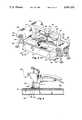
- FIG. 1is a partial, perspective view of an ultrasonic edge cutting and sealing apparatus embodying features of the present invention
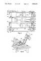
- FIG. 2is a partial, perspective view showing details of another embodiment of the present invention.
- FIG. 3is a partial, perspective view of yet another embodiment of the present invention.
- FIG. 4is a view, partly in section, taken along line 4--4 of FIG. 3;
- FIG. 5is a partial, plan view, partly diagrammatic, of still another embodiment of the present invention.
- FIG. 6is a partial, perspective view showing details of another embodiment of the present invention.
- FIG. 7is a partial, perspective view showing details of yet another embodiment of the present invention.
- an ultrasonic cutting and sealing apparatusfor cutting and sealing the cut edges of semipermeable and at least partially thermoplastic fabric material.
- the apparatus 10includes a support, generally indicated by reference number 12, for positioning the material for cutting and sealing.
- the support 12includes a substantially flat, generally horizontal platform 14 mounted on a plurality of supporting legs 16 or the like.
- a vacuum meansgenerally indicated by reference number 18, is a plurality of apertures 20 are shown formed in the platform 14.
- the aperturesare connected to a source of vacuum (not shown).
- the apertures 20are spaced about the platform 14 so that, when vacuum is applied to the apertures 20, material resting atop the platform 14 is pulled thereagainst and immobilized while being cut and sealed.
- the present apparatusis perfectly capable of operating with material that is impermeable, it is particularly adapted to cutting and sealing cut edges of automotive safety bag material.
- materialis semipermeable, offering sufficient resistance to a flow of air therethrough to facilitate a rapid inflation of an air bag made therefrom but permitting air to exit at a rate sufficient to allow a relatively rapid deflation of the air bag.
- the material typically used with the present inventionhas a permeability within a range that permits the material to be held in place by a vacuum not exceeding 74 inches of water.
- An ultrasonic cutteris shown mounted on a robotic cutting arm, generally indicated by reference numeral 24.
- the cutter 22includes an ultrasonically driven horn 26, which has a cutting tip 28.
- the cutter 22also has an anvil 30.
- the robotic cutting arm 24is mounted proximate the platform 14 and is articulated to provide three degrees of freedom in which to guide the cutter 22 along a two-dimensional cutting path.
- a pickup member 31Shown attached to the cutter 22 is a pickup member 31.
- the pickup member 31is connected to a source of vacuum (not shown).
- the robotic cutting arm 24may be positioned over the cut portion and vacuum applied to the pickup member 31, pulling the material thereagainst. The robotic cutter arm 24 may then be maneuvered to lift the cut portion and remove it from the platform 14.
- FIG. 2 of the drawingsshows another embodiment of the present invention.
- This embodimentincludes a support, generally indicated by reference numeral 12, for positioning material 32 for cutting and sealing.
- the support 12includes a substantially flat, generally horizontal platform 14 mounted on a plurality of supporting legs 16 or the like. Defined in the platform 14 are a plurality of apertures 20 connected to a source of vacuum (not shown) that pulls the material 32 against the platform 14 to immobilize the material 32 while it is being cut and sealed.
- a cutteris shown as it would typically be manually operated.
- the cutter 22includes an ultrasonically driven horn 26, which has a cutting tip 28.
- the cutter 22also has a guide member 34 attached thereto with a bracket 35.
- the guide member 34is substantially circular in horizontal cross section, and it and the cutting tip 28 have collinear axes.
- An anvil 30is formed as an integral part of the guide member 34.
- the platform 14 of this embodimentdefines a channel 36 formed therein to function as a guiding means for the cutter 22.
- the guide member 34 attached to the cutter 22fits into the channel 36, which describes a path coincident with the shape to be cut from the material 32.
- the guide member 34, and the cutter 22 to which it is attachedfollow the path defined by the channel 36, cutting the material 32 in a desired configuration.
- the circularity of the horizontal cross section of the guide member 34maintains the cutting tip 28 in the center of the channel 36 regardless of the orientation of the cutter 22.
- FIG. 3 of the drawingsShown in FIG. 3 of the drawings is another embodiment of the present invention.
- This embodimentincludes a cutter positioning mechanism, generally indicated by reference numeral 38.
- the cutter positioning mechanism 38includes a gantry support, generally indicated by reference numeral 40, which includes an elongate bridge member 42 horizontally supported at each end by a gantry leg 44.
- a longitudinal positioning means, or mechanism 46Movably mounted on the bridge 42 is a longitudinal positioning means, or mechanism 46, that horizontally moves a cutter, generally indicated by reference numeral 22, along a longitudinal axis to provide longitudinal components of motion to the cutter 22.
- a vertical positioning means, or mechanism 48Movably mounted on the longitudinal positioning mechanism 46 is a vertical positioning means, or mechanism 48, that vertically moves the cutter 22 into engagement with material 32 to be cut and out of engagement with the material 32 when cutting has been completed.
- a beam 49extending at right angles to the bridge member 42.
- a lateral positioning means, or mechanism 50Movably mounted on the beam 49 is a lateral positioning means, or mechanism 50, that horizontally moves along a lateral axis to provide lateral components of motion to the cutter 22.
- the lateral axisis at right angles to the longitudinal axis.
- this embodimentincludes a support, generally indicated by reference number 12, for positioning the material 32 for cutting and sealing.
- the support 12includes a substantially flat, generally horizontal platform 14 mounted on a plurality of supporting legs 16 or the like.
- a vacuum means as previously describedis also included in the embodiment for immobilizing the material while being cut and sealed.
- Alternative methods for immobilizing material to be cut and sealedinclude a shaped weight (not shown) to press the material 32 against the platform 14 and nontransferring adhesive (also not shown) disposed on the platform 14 to temporarily adhere material 32 being supported thereby.
- the platform 14has a foot end and a head end, generally indicated by reference numerals 52 and 54 respectively.
- a supply reel 56is rotatably mounted proximate the foot end 52 of the platform 14, and a takeup reel 58 is rotatably mounted proximate the head end 54.
- the reels 56 and 58may be mounted on A-frame supports 60 or the like.
- the supply reel 56 and the takeup reel 58form part of a feeding means, or mechanism, generally indicated by reference numeral 62.
- a quantity of material 32is stored on the supply reel 56 and may be pulled therefrom for positioning and cutting atop the platform 14.
- the takeup reel 58receives and stores material 32 remaining after a desired portion has been cut therefrom.
- the feeding mechanism 62also includes a drive means, or mechanism, generally indicated by reference numeral 64.
- the drive mechanism 64includes electric motors 66, a motor 66 being connected to each reel 56 and 58 to impart rotation thereto when positioning or removing material 32.
- FIG. 4is a view, taken along the line 4--4 of FIG. 3, of the cutter 22. Shown is the cutter 22 and portions of the platform 14 and material 32, the latter two items being shown in section.
- the cutter 22is shown including an ultrasonically driven horn 26 having a cutting tip 28.
- An anvil 30is formed as an integral part of a guide member 34, which is attached to the cutter 22 by a bracket 35.
- Apertures 20are shown formed in the platform 14.
- the apertures 20are connected to a source of vacuum (not shown).
- the apertures 20are spaced about the platform 14 so that, when vacuum is applied to the apertures 20, material 32 resting atop the platform 14 is pulled thereagainst and immobilized while being cut and sealed.
- This embodimentincludes a support, generally indicated by reference number 12, for positioning the material 32 for cutting and sealing.
- the support 12includes a substantially flat, generally horizontal, hardened steel platform 14.
- the embodimentincludes vacuum means having apertures defined in the hardened steel platform 14 and connected to a source of vacuum. As in previously described embodiments, the apertures are spaced about the platform 14 so that, when vacuum is applied, material 32 resting atop the platform 14 is pulled thereagainst and immobilized while being cut and sealed.
- An ultrasonic cutteris shown mounted on a robotic cutting arm, generally indicated by reference numeral 24.
- the cutter 22is not shown in detail in this figure but is as described in previous embodiments, including an ultrasonically driven horn having a cutting tip.
- the hardened steel portion of the platform 14serves as an anvil.
- the robotic cutting arm 24is mounted proximate the platform 14 and is articulated to provide three degrees of freedom in which to guide the cutter 22 along a two-dimensional cutting path.
- a cutter controlleris included to control the operation of the robotic cutting arm 24 and the cutter 22.
- the embodiments of the present inventioninclude one or more controllers, and these may be disposed in separate, interconnected enclosures; however, as shown in FIG. 5, they are represented as being disposed in one enclosure, generally indicated by reference numeral 68.
- the platform 14has a foot end and a head end, generally indicated by reference numerals 52 and 54 respectively.
- a supply reel 56is rotatably mounted on an A-frame support 60 proximate the foot end 52 of the platform 14, and a takeup reel 58 is similarly rotatably mounted proximate the head end 54.
- the reels 56 and 58may be mounted on A-frame supports 60 or the like.
- the supply reel 56 and the takeup reel 58form part of a feeding means, or mechanism, generally indicated by reference numeral 62.
- a quantity of material 32is stored on the supply reel 56 and may be pulled therefrom for positioning and cutting atop the platform 14.
- the takeup reel 58receives and stores material 32 remaining after a desired portion has been cut therefrom.
- the feeding mechanism 62also includes a drive means, or mechanism, generally indicated by reference numeral 64.
- the drive mechanism 64includes electric motors 66, a motor 66 being connected to each reel 56 and 58 to impart rotation thereto when positioning or removing material 32.
- the drive means 64also includes a motor control means, or feed controller, connected to the motor 66 to initiate and terminate rotation of the takeup reel 58 and the supply reel 56.
- controllersare represented in FIG. 5 as being disposed in one enclosure, generally indicated by reference numeral 68.
- Each cutter 67includes an ultrasonically driven horn (not shown) that impinges a hardened steel anvil 69 rotatably mounted in effective apposition thereto.
- a robotic stacking arm 70having a pickup means, generally indicated by reference numeral 72, for temporarily coupling the robotic stacking arm 70 to a portion cut from the material 32 to facilitate removal of the latter from the platform 14.
- the pickup means 72includes at least one pickup member 74 positionable by the robotic stacking arm 70 against the portion cut from the material 32.
- the pickup member 74is connected to a source of vacuum, the vacuum being communicated through an orifice in the pickup member 74 to hold the portion cut from the material 32 against the pickup member 74.
- the pickup meansalso includes a pickup controlling means for controlling the application of vacuum to the pickup member.
- the pickup controlling meansor pickup controller, controls the movement of the robotic stacking arm 70 and controls the application of vacuum to the pickup member 74 to pick up the portion cut from the material 32.
- controllersare represented in FIG. 5 as being disposed in one enclosure, generally indicated by reference numeral 68.
- original operating parametersmay be manually selected or input to the controller 68, as suggested by the FIG. 78; or, if a number of such cutting installations are being operated at one site, a master controller might be used to input such data to controllers located at each installation.
- At least one bin 76is provided to receive and store portions cut from the material 32.
- the robotic stacking arm 70positions the pickup member 74 against a portion cut from the material 32, vacuum is applied to the pickup member 74 to hold the cut material against it, the robotic stacking arm 70 moves the pickup member 74 and the cut material held thereagainst away from the platform 14 to a position above the bin 76; and vacuum is removed from the pickup member 74, allowing the cut material to drop into the bin 76.
- FIG. 5provision may be made for operating more than one cutter 22 simultaneously; and such an embodiment is illustrated by FIG. 5. Dashed lines are used in FIG. 5 to show one possible mode of operation, which would include positioning the robotic cutting arm 24 above the material 32 on one platform 14 while the robotic stacking arm 70 is positioned above the material 32 on the other platform 14. While the material 32 on one platform 14 is being out, the material previously cut on the other platform 14 is being removed.
- FIG. 6includes details illustrating another embodiment of the present invention.
- the embodimentincludes a platform 14 upon which material is positioned for cutting and sealing, the material being held in position by a vacuum means including a vacuum system acting through apertures 20 in the platform 14 as previously described.
- a robotic cutting arm 24positions a cutter 22 having an ultrasonically driven horn 26 over the platform 14.
- the anvil 80is configured to match the pattern of a portion to be cut from the material and, in fact, may be cut to match several different patterns or even to cover or form a substantial portion of the surface of the platform 14.
- the configured anvil 80may be inlaid into the platform 14 so that its upper surface is substantially coplanar with that of the platform 14, thus enhancing the effectiveness of the vacuum means.
- the platform 14has at least one slightly raised, hardened steel energy director, or anvil 82, shaped to match a portion to be cut from the material.
- the ultrasonically driven horn 26 usedrather than having a cutting tip, includes a flat plate 84 for simultaneously pressing material (not shown) disposed between the plate 84 and the anvil 82 against all portions of the raised anvil 82 and cutting and sealing the material; and the cutter 22 need have only one degree of freedom and need not be guided along a path coincident with the configuration of the portions to be cut from the material.
Landscapes
- Engineering & Computer Science (AREA)
- Life Sciences & Earth Sciences (AREA)
- Forests & Forestry (AREA)
- Mechanical Engineering (AREA)
- Textile Engineering (AREA)
- Treatment Of Fiber Materials (AREA)
Abstract
Description
Claims (36)
Priority Applications (1)
| Application Number | Priority Date | Filing Date | Title |
|---|---|---|---|
| US07/539,560US5061331A (en) | 1990-06-18 | 1990-06-18 | Ultrasonic cutting and edge sealing of thermoplastic material |
Applications Claiming Priority (1)
| Application Number | Priority Date | Filing Date | Title |
|---|---|---|---|
| US07/539,560US5061331A (en) | 1990-06-18 | 1990-06-18 | Ultrasonic cutting and edge sealing of thermoplastic material |
Publications (1)
| Publication Number | Publication Date |
|---|---|
| US5061331Atrue US5061331A (en) | 1991-10-29 |
Family
ID=24151750
Family Applications (1)
| Application Number | Title | Priority Date | Filing Date |
|---|---|---|---|
| US07/539,560Expired - Fee RelatedUS5061331A (en) | 1990-06-18 | 1990-06-18 | Ultrasonic cutting and edge sealing of thermoplastic material |
Country Status (1)
| Country | Link |
|---|---|
| US (1) | US5061331A (en) |
Cited By (59)
| Publication number | Priority date | Publication date | Assignee | Title |
|---|---|---|---|---|
| US5256238A (en)* | 1991-01-10 | 1993-10-26 | Gerber Garment Technology, Inc. | Vertically removable and emplacable tool carriage for use with a plurality of work supporting tables |
| EP0595511A1 (en) | 1992-10-27 | 1994-05-04 | Moore Business Forms, Inc. | Business form with integral label and method and apparatus for producing same |
| US5632831A (en)* | 1994-08-04 | 1997-05-27 | Superpac, Inc. | System and method for cutting and splicing polymeric webs |
| US5735984A (en)* | 1994-11-08 | 1998-04-07 | Minnesota Mining And Manufacturing Company | Method of aperturing thin sheet materials |
| US5846584A (en)* | 1997-04-30 | 1998-12-08 | Mars, Incorporated | Apparatus and method for forming cereal food products |
| US5871783A (en)* | 1996-08-22 | 1999-02-16 | Mars, Incorporated | Apparatus for ultrasonically forming confectionery products |
| US5879494A (en)* | 1996-09-23 | 1999-03-09 | Minnesota Mining And Manufacturing Company | Method of aperturing thin sheet materials |
| US5888639A (en) | 1994-07-11 | 1999-03-30 | Newell Operating Co | Cellular panel and method and apparatus for making the same |
| WO1999041076A1 (en)* | 1998-02-12 | 1999-08-19 | Tilia International, Incorporated | Plastic bag sealing apparatus with an ultracapacitor discharging power circuit |
| US6017406A (en)* | 1996-12-20 | 2000-01-25 | Kimberly-Clark Worldwide, Inc. | Methods for making absorbent articles with separate leg cuffs and waist pieces |
| US6098684A (en)* | 1997-03-31 | 2000-08-08 | Brother Kogyo Kabushiki Kaisha | Ultrasonic welding/cutting machine |
| US6231330B1 (en) | 1996-08-22 | 2001-05-15 | Mars, Incorporated | Ultrasonic forming of confectionery products |
| WO2001039941A1 (en)* | 1999-12-03 | 2001-06-07 | Bierrebi S.P.A. | An apparatus for cutting pieces of material into appropriate shaped portions |
| US6318248B1 (en) | 1996-11-27 | 2001-11-20 | Mars, Incorporated | Apparatus for ultrasonic molding |
| US6368647B1 (en) | 1998-12-29 | 2002-04-09 | Mars, Incorporated | Ultrasonically activated continuous slitter apparatus and method |
| US20020127310A1 (en)* | 1998-12-07 | 2002-09-12 | Capodieci Roberto A. | Cereal food product and method |
| US20020148555A1 (en)* | 2001-04-16 | 2002-10-17 | Omega International | Method of cutting and sealing material |
| US6574944B2 (en) | 2001-06-19 | 2003-06-10 | Mars Incorporated | Method and system for ultrasonic sealing of food product packaging |
| ES2189547A1 (en)* | 1998-12-17 | 2003-07-01 | Com De Tecnologia Sanitaria S | Machine for cutting and welding of continuous tape of plastic material, especially for security belts of vehicles and alike. |
| US6635292B2 (en) | 2001-10-26 | 2003-10-21 | Mars, Incorporated | Ultrasonic rotary forming of food products |
| US6655948B2 (en) | 2001-08-31 | 2003-12-02 | Mars, Incorporated | System of ultrasonic processing of pre-baked food product |
| US20040061262A1 (en)* | 2002-09-30 | 2004-04-01 | Glenn Cowelchuk | Instrument panel skin for covering airbag and method of making same |
| US6743322B2 (en)* | 2001-01-24 | 2004-06-01 | Printmark Industries Inc. | Process for manufacturing thermoplastic-trimmed article of clothing |
| EP1468794A1 (en)* | 2003-04-15 | 2004-10-20 | Telsonic Holding AG | Apparatus and method for making apertures in workpieces by an ultrasonic source |
| US6835346B1 (en)* | 1999-11-17 | 2004-12-28 | Pearl Kogyo Co., Ltd. | Method and apparatus for processing a linear groove to an air bag portion of a skin for a vehicle |
| EP1579966A1 (en)* | 2004-03-24 | 2005-09-28 | Equipment Poler, S.l. | Fabric cutting system |
| WO2005097474A1 (en)* | 2004-04-07 | 2005-10-20 | Otto Bock Scandinavia Ab | Method and device for cutting a laminate and a laminated product |
| US7003928B2 (en) | 2002-10-04 | 2006-02-28 | Jcs/Thg, Llc | Appliance for vacuum sealing food containers |
| US20060044376A1 (en)* | 2004-08-26 | 2006-03-02 | Baird Richard W | Apparatus and methods for applying images to a surface |
| WO2006067512A1 (en)* | 2004-12-24 | 2006-06-29 | Magellan Textile Holdings Limited | A method and apparatus for shaping of fabrics |
| US7076929B2 (en) | 2002-10-04 | 2006-07-18 | Jcs/Thg, Llc | Appliance for vacuum sealing food containers |
| US7131250B2 (en) | 2002-10-04 | 2006-11-07 | Jcs/Thg, Llp | Appliance for vacuum sealing food containers |
| DE102005036416A1 (en)* | 2005-07-29 | 2007-02-01 | Hans Striewski | Apparatus for cutting carpet and welding the pile |
| US20070234861A1 (en)* | 2006-04-05 | 2007-10-11 | Mikkelsen Steen B | Method and apparatus for fray-free textile cutting |
| US20070234862A1 (en)* | 2006-04-05 | 2007-10-11 | Mikkelsen Graphic Engineering, Inc. | Method and Apparatus for Fray-Free Cutting with Laser Anti-Fray Inducement |
| US20070296109A1 (en)* | 2006-02-21 | 2007-12-27 | Francis Vezina | Block tumbler with block-immobilizing device |
| US20080048367A1 (en)* | 2004-09-23 | 2008-02-28 | Meadwestvaco Corporation | Method for Forming Packaging Blanks From Plastic Sheet |
| US20080083481A1 (en)* | 2004-01-15 | 2008-04-10 | Georgia Tech Research Corporation | Method and Apparatus to Create Electrical Junctions for Information Routing in Textile Structures |
| US20100294814A1 (en)* | 2009-05-20 | 2010-11-25 | Paul Urban Geiwald | Method for creating garment cuffs with stretch and recovery characteristics |
| US20140374020A1 (en)* | 2013-06-21 | 2014-12-25 | Miller Weldmaster Corporation | Method and apparatus for welding a curved seam |
| CN104674537A (en)* | 2015-03-27 | 2015-06-03 | 苏州大学 | Space cutting device and space cutting method for fabric with complicated shape |
| US20150174817A1 (en)* | 2013-12-20 | 2015-06-25 | Google Inc. | System for constructing balloon envelopes |
| US20160158876A1 (en)* | 2014-12-09 | 2016-06-09 | GM Global Technology Operations LLC | Ultrasonic welding of composites using c frame tooling |
| CN106436263A (en)* | 2016-12-06 | 2017-02-22 | 江苏英普科电子材料有限公司 | Ultrasonic transverse cutting machine |
| CN107116805A (en)* | 2016-02-24 | 2017-09-01 | 耐克创新有限合伙公司 | Vacuum cutter |
| CN108193476A (en)* | 2018-01-09 | 2018-06-22 | 海宁市中发纺织有限公司 | A kind of ultrasonic wave knitted fabric cutter device |
| US10086561B1 (en) | 2016-03-24 | 2018-10-02 | X Development Llc | Automated balloon assembly machine |
| US20190143553A1 (en)* | 2016-10-25 | 2019-05-16 | Nakata Coating Co., Ltd. | Portal-shaped tear processing device |
| US10293913B1 (en) | 2014-07-25 | 2019-05-21 | Loon Llc | Termination assembly for use with balloon envelopes |
| IT201900009180A1 (en)* | 2019-06-17 | 2020-12-17 | Gmi Srl | DEVICE AND METHOD FOR CUTTING CARPET |
| US20210260712A1 (en)* | 2020-02-20 | 2021-08-26 | The Boeing Company | Methods of ultrasonic drilling for forming perforations in composite materials |
| US11168489B2 (en) | 2014-12-22 | 2021-11-09 | Cover Care, Llc | Mesh fence material and method for making thereof |
| US11377783B2 (en)* | 2016-07-14 | 2022-07-05 | Cafe24 Corp. | Device and method for cutting raw fabric |
| US11478994B1 (en)* | 2020-09-09 | 2022-10-25 | Kyle W. Burns | HDPE covers for wastewater treatment lagoons, and HDPE patches thereon in service for further attachments |
| US20230071522A1 (en)* | 2021-09-09 | 2023-03-09 | Lockheed Martin Corporation | Ultrasonic Cutting System and Method |
| US20230081765A1 (en)* | 2021-09-10 | 2023-03-16 | Chun-Fu Kuo | Processing device for processing opposing edges of a flexible sheet body |
| US20230271387A1 (en)* | 2022-02-28 | 2023-08-31 | Capital One Services, Llc | System for sealing an article |
| US12194689B1 (en) | 2020-09-09 | 2025-01-14 | Kyle W. Burns | HDPE covers for wastewater treatment lagoons, and HDPE patches thereon in service for further attachments |
| EP4606542A1 (en) | 2024-02-21 | 2025-08-27 | R. Van Den Hanenberg B.V. | Method of forming an elastomeric foam element |
Citations (17)
| Publication number | Priority date | Publication date | Assignee | Title |
|---|---|---|---|---|
| US3457132A (en)* | 1964-12-28 | 1969-07-22 | Tetra Pak Ab | Apparatus for severing and sealing webs of heat sealable packaging material in a single operation |
| US3657033A (en)* | 1969-03-26 | 1972-04-18 | Ultrasonic Systems | Method and apparatus for continuous cutting and joining of thermoplastic sheet material |
| US4157719A (en)* | 1977-02-17 | 1979-06-12 | Beltx Corporation | Method and apparatus for ultrasonic sealing and cutting, and tabs produced thereby |
| US4224091A (en)* | 1977-12-01 | 1980-09-23 | Branson Ultrasonics Corp. | Method of producing corners in channel material using ultrasonic energy |
| US4392257A (en)* | 1979-10-04 | 1983-07-12 | Furga Giulio S | Method of making dresses for dolls and the like and product obtained by this method |
| US4491491A (en)* | 1983-11-02 | 1985-01-01 | Simmons U.S.A. Corporation | Ultrasonic separation apparatus |
| US4496407A (en)* | 1983-11-28 | 1985-01-29 | Springs Industries, Inc. | Apparatus and process for ultrasonically cutting off predetermined widths of selvages and sealing the cut edges of textile fabric |
| US4534819A (en)* | 1983-11-28 | 1985-08-13 | Springs Industries, Inc. | Woven textile fabric having an ultrasonically cut and sealed edge and apparatus and process for producing same |
| US4560427A (en)* | 1984-12-03 | 1985-12-24 | Branson Ultrasonics Corporation | Ultrasonic seal and cut method and apparatus |
| US4610750A (en)* | 1985-04-05 | 1986-09-09 | Branson Ultrasonics Corporation | Ultrasonic cut and seal apparatus |
| US4630987A (en)* | 1983-08-18 | 1986-12-23 | Siemens Aktiengesellschaft | Peripheral auxiliary system for the automatic feeding and unloading of a stamping/nibbling machine |
| US4693771A (en)* | 1983-11-28 | 1987-09-15 | Springs Industries, Inc. | Woven textile fabric having an ultrasonically cut and sealed edge and apparatus and process for producing same |
| US4750970A (en)* | 1986-07-21 | 1988-06-14 | Malosh Peter G | Plastic sheet sealing/welding machine |
| US4804432A (en)* | 1985-12-27 | 1989-02-14 | Bodiguard Technologies, Inc. | Manufacture of gloves and the like |
| US4896014A (en)* | 1987-10-13 | 1990-01-23 | Mazda Motor Corporation | Method of automatically grinding an electrode for spot welding use and apparatus for effecting said method |
| US4900379A (en)* | 1988-05-20 | 1990-02-13 | The Boeing Company | Method for producing composite materials |
| US4927479A (en)* | 1983-11-02 | 1990-05-22 | Boeck Josef | Process and plant for pressing flexible sheets |
- 1990
- 1990-06-18USUS07/539,560patent/US5061331A/ennot_activeExpired - Fee Related
Patent Citations (17)
| Publication number | Priority date | Publication date | Assignee | Title |
|---|---|---|---|---|
| US3457132A (en)* | 1964-12-28 | 1969-07-22 | Tetra Pak Ab | Apparatus for severing and sealing webs of heat sealable packaging material in a single operation |
| US3657033A (en)* | 1969-03-26 | 1972-04-18 | Ultrasonic Systems | Method and apparatus for continuous cutting and joining of thermoplastic sheet material |
| US4157719A (en)* | 1977-02-17 | 1979-06-12 | Beltx Corporation | Method and apparatus for ultrasonic sealing and cutting, and tabs produced thereby |
| US4224091A (en)* | 1977-12-01 | 1980-09-23 | Branson Ultrasonics Corp. | Method of producing corners in channel material using ultrasonic energy |
| US4392257A (en)* | 1979-10-04 | 1983-07-12 | Furga Giulio S | Method of making dresses for dolls and the like and product obtained by this method |
| US4630987A (en)* | 1983-08-18 | 1986-12-23 | Siemens Aktiengesellschaft | Peripheral auxiliary system for the automatic feeding and unloading of a stamping/nibbling machine |
| US4491491A (en)* | 1983-11-02 | 1985-01-01 | Simmons U.S.A. Corporation | Ultrasonic separation apparatus |
| US4927479A (en)* | 1983-11-02 | 1990-05-22 | Boeck Josef | Process and plant for pressing flexible sheets |
| US4693771A (en)* | 1983-11-28 | 1987-09-15 | Springs Industries, Inc. | Woven textile fabric having an ultrasonically cut and sealed edge and apparatus and process for producing same |
| US4496407A (en)* | 1983-11-28 | 1985-01-29 | Springs Industries, Inc. | Apparatus and process for ultrasonically cutting off predetermined widths of selvages and sealing the cut edges of textile fabric |
| US4534819A (en)* | 1983-11-28 | 1985-08-13 | Springs Industries, Inc. | Woven textile fabric having an ultrasonically cut and sealed edge and apparatus and process for producing same |
| US4560427A (en)* | 1984-12-03 | 1985-12-24 | Branson Ultrasonics Corporation | Ultrasonic seal and cut method and apparatus |
| US4610750A (en)* | 1985-04-05 | 1986-09-09 | Branson Ultrasonics Corporation | Ultrasonic cut and seal apparatus |
| US4804432A (en)* | 1985-12-27 | 1989-02-14 | Bodiguard Technologies, Inc. | Manufacture of gloves and the like |
| US4750970A (en)* | 1986-07-21 | 1988-06-14 | Malosh Peter G | Plastic sheet sealing/welding machine |
| US4896014A (en)* | 1987-10-13 | 1990-01-23 | Mazda Motor Corporation | Method of automatically grinding an electrode for spot welding use and apparatus for effecting said method |
| US4900379A (en)* | 1988-05-20 | 1990-02-13 | The Boeing Company | Method for producing composite materials |
Cited By (113)
| Publication number | Priority date | Publication date | Assignee | Title |
|---|---|---|---|---|
| US5256238A (en)* | 1991-01-10 | 1993-10-26 | Gerber Garment Technology, Inc. | Vertically removable and emplacable tool carriage for use with a plurality of work supporting tables |
| EP0595511A1 (en) | 1992-10-27 | 1994-05-04 | Moore Business Forms, Inc. | Business form with integral label and method and apparatus for producing same |
| US6045890A (en) | 1994-07-11 | 2000-04-04 | Newell Operating Company | Cellular panel and method and apparatus for making the same |
| US6284347B1 (en) | 1994-07-11 | 2001-09-04 | Newell Operating Company | Cellular panel and method and apparatus for making the same |
| US6908661B2 (en) | 1994-07-11 | 2005-06-21 | Newell Operating Company | Cellular panel and method and apparatus for making the same |
| US5888639A (en) | 1994-07-11 | 1999-03-30 | Newell Operating Co | Cellular panel and method and apparatus for making the same |
| US5632831A (en)* | 1994-08-04 | 1997-05-27 | Superpac, Inc. | System and method for cutting and splicing polymeric webs |
| US5735984A (en)* | 1994-11-08 | 1998-04-07 | Minnesota Mining And Manufacturing Company | Method of aperturing thin sheet materials |
| US6530767B1 (en) | 1996-08-22 | 2003-03-11 | Mars Incorporated | Ultrasonic forming of confectionery products |
| US6431849B1 (en) | 1996-08-22 | 2002-08-13 | Mars, Incorporated | Ultrasonic forming of confectionery products |
| US6607765B2 (en) | 1996-08-22 | 2003-08-19 | Mars, Incorporated | Ultrasonic forming of confectionery products |
| US5871783A (en)* | 1996-08-22 | 1999-02-16 | Mars, Incorporated | Apparatus for ultrasonically forming confectionery products |
| US20030003207A1 (en)* | 1996-08-22 | 2003-01-02 | Capodieci Roberto A. | Ultrasonic forming of confectionery products |
| US6210728B1 (en) | 1996-08-22 | 2001-04-03 | Mars Incorporated | Ultrasonic forming of confectionery products |
| US6231330B1 (en) | 1996-08-22 | 2001-05-15 | Mars, Incorporated | Ultrasonic forming of confectionery products |
| US5879494A (en)* | 1996-09-23 | 1999-03-09 | Minnesota Mining And Manufacturing Company | Method of aperturing thin sheet materials |
| US6318248B1 (en) | 1996-11-27 | 2001-11-20 | Mars, Incorporated | Apparatus for ultrasonic molding |
| US6517879B2 (en) | 1996-11-27 | 2003-02-11 | Mars Incorporated | Method and apparatus for ultrasonic molding |
| US6017406A (en)* | 1996-12-20 | 2000-01-25 | Kimberly-Clark Worldwide, Inc. | Methods for making absorbent articles with separate leg cuffs and waist pieces |
| US6440239B1 (en) | 1996-12-20 | 2002-08-27 | Kimberly-Clark Worldwide, Inc. | Methods for making absorbent articles with separate leg cuffs and waist pieces |
| US6098684A (en)* | 1997-03-31 | 2000-08-08 | Brother Kogyo Kabushiki Kaisha | Ultrasonic welding/cutting machine |
| US6403132B1 (en) | 1997-04-30 | 2002-06-11 | Mars, Incorporated | System and method for forming cereal food products |
| US5846584A (en)* | 1997-04-30 | 1998-12-08 | Mars, Incorporated | Apparatus and method for forming cereal food products |
| US6058998A (en)* | 1998-02-12 | 2000-05-09 | Tilia International, Inc. | Plastic bag sealing apparatus with an ultracapacitor discharging power circuit |
| WO1999041076A1 (en)* | 1998-02-12 | 1999-08-19 | Tilia International, Incorporated | Plastic bag sealing apparatus with an ultracapacitor discharging power circuit |
| US20020127310A1 (en)* | 1998-12-07 | 2002-09-12 | Capodieci Roberto A. | Cereal food product and method |
| ES2189547A1 (en)* | 1998-12-17 | 2003-07-01 | Com De Tecnologia Sanitaria S | Machine for cutting and welding of continuous tape of plastic material, especially for security belts of vehicles and alike. |
| ES2189547B1 (en)* | 1998-12-17 | 2004-04-01 | Comercial De Tecnologia Sanitaria, S.A. | MACHINE FOR THE CUTTING AND WELDING OF CONTINUOUS TAPE OF PLASTIC MATERIAL; IN SPECIAL FOR VEHICLE AND SIMILAR SEAT BELTS. |
| US20020119225A1 (en)* | 1998-12-29 | 2002-08-29 | Capodieci Roberto A. | Ultrasonically activated continuous slitter apparatus and method |
| US7141259B2 (en) | 1998-12-29 | 2006-11-28 | Mars, Incorporated | Ultrasonically activated continuous slitter apparatus and method |
| US6368647B1 (en) | 1998-12-29 | 2002-04-09 | Mars, Incorporated | Ultrasonically activated continuous slitter apparatus and method |
| US6835346B1 (en)* | 1999-11-17 | 2004-12-28 | Pearl Kogyo Co., Ltd. | Method and apparatus for processing a linear groove to an air bag portion of a skin for a vehicle |
| WO2001039941A1 (en)* | 1999-12-03 | 2001-06-07 | Bierrebi S.P.A. | An apparatus for cutting pieces of material into appropriate shaped portions |
| CN101046058B (en)* | 1999-12-03 | 2011-06-22 | 比雷比股份公司 | Equipment for cutting sheets into suitable shapes |
| CN1308124C (en)* | 1999-12-03 | 2007-04-04 | 比雷比股份公司 | Equipment for cutting sheets into suitable shapes |
| US7047855B2 (en) | 1999-12-03 | 2006-05-23 | Bierrebi S.P.A. | Apparatus for cutting pieces of material into appropriate shaped portions |
| US20060096433A1 (en)* | 1999-12-03 | 2006-05-11 | Bierrebi S.P.A. | Apparatus for cutting pieces of material into appropriate shaped portion |
| EP1426153A3 (en)* | 1999-12-03 | 2004-07-21 | Bierrebi S.P.A. | An apparatus for cutting pieces of material into appropriate shaped portions |
| US6743322B2 (en)* | 2001-01-24 | 2004-06-01 | Printmark Industries Inc. | Process for manufacturing thermoplastic-trimmed article of clothing |
| US20020148555A1 (en)* | 2001-04-16 | 2002-10-17 | Omega International | Method of cutting and sealing material |
| US6574944B2 (en) | 2001-06-19 | 2003-06-10 | Mars Incorporated | Method and system for ultrasonic sealing of food product packaging |
| US8028503B2 (en) | 2001-06-19 | 2011-10-04 | Robert Bosch Gmbh | Method and system for ultrasonic sealing of food product packaging |
| US6655948B2 (en) | 2001-08-31 | 2003-12-02 | Mars, Incorporated | System of ultrasonic processing of pre-baked food product |
| US6635292B2 (en) | 2001-10-26 | 2003-10-21 | Mars, Incorporated | Ultrasonic rotary forming of food products |
| US20040061262A1 (en)* | 2002-09-30 | 2004-04-01 | Glenn Cowelchuk | Instrument panel skin for covering airbag and method of making same |
| US7076929B2 (en) | 2002-10-04 | 2006-07-18 | Jcs/Thg, Llc | Appliance for vacuum sealing food containers |
| US7454884B2 (en) | 2002-10-04 | 2008-11-25 | Sunbeam Products, Inc. | Appliance for vacuum sealing food containers |
| US7401452B2 (en) | 2002-10-04 | 2008-07-22 | Sunbeam Products, Inc. | Appliance for vacuum sealing food containers |
| US7131250B2 (en) | 2002-10-04 | 2006-11-07 | Jcs/Thg, Llp | Appliance for vacuum sealing food containers |
| US7003928B2 (en) | 2002-10-04 | 2006-02-28 | Jcs/Thg, Llc | Appliance for vacuum sealing food containers |
| US7231753B2 (en) | 2002-10-04 | 2007-06-19 | Sunbeam Products, Inc. | Appliance for vacuum sealing food containers |
| EP1468794A1 (en)* | 2003-04-15 | 2004-10-20 | Telsonic Holding AG | Apparatus and method for making apertures in workpieces by an ultrasonic source |
| US20080083481A1 (en)* | 2004-01-15 | 2008-04-10 | Georgia Tech Research Corporation | Method and Apparatus to Create Electrical Junctions for Information Routing in Textile Structures |
| US20180102619A1 (en)* | 2004-01-15 | 2018-04-12 | Georgia Institute Of Technology | Method and apparatus to create electrical junctions for information routing in textile structures |
| EP1579966A1 (en)* | 2004-03-24 | 2005-09-28 | Equipment Poler, S.l. | Fabric cutting system |
| US20080250906A1 (en)* | 2004-04-07 | 2008-10-16 | Otto Bock Scandinavia Ab | Method and Device for Cutting a Laminate and Laminate Product |
| WO2005097474A1 (en)* | 2004-04-07 | 2005-10-20 | Otto Bock Scandinavia Ab | Method and device for cutting a laminate and a laminated product |
| US8110053B2 (en) | 2004-04-07 | 2012-02-07 | Otto Bock Scandinavia Ab | Method and device for cutting a laminate and laminate product |
| US7350890B2 (en) | 2004-08-26 | 2008-04-01 | The Boeing Company | Apparatus and methods for applying images to a surface |
| US20080152807A1 (en)* | 2004-08-26 | 2008-06-26 | The Boeing Company | Applying images to a surface |
| US20060044376A1 (en)* | 2004-08-26 | 2006-03-02 | Baird Richard W | Apparatus and methods for applying images to a surface |
| US20080048367A1 (en)* | 2004-09-23 | 2008-02-28 | Meadwestvaco Corporation | Method for Forming Packaging Blanks From Plastic Sheet |
| GB2421477B (en)* | 2004-12-24 | 2008-02-27 | Sara Lee Corp | A method and apparatus for shaping of fabrics |
| WO2006067512A1 (en)* | 2004-12-24 | 2006-06-29 | Magellan Textile Holdings Limited | A method and apparatus for shaping of fabrics |
| US20090026661A1 (en)* | 2004-12-24 | 2009-01-29 | Richard Sturman | Method and Apparatus for Shaping of Fabrics |
| DE102005036416A1 (en)* | 2005-07-29 | 2007-02-01 | Hans Striewski | Apparatus for cutting carpet and welding the pile |
| US20070296109A1 (en)* | 2006-02-21 | 2007-12-27 | Francis Vezina | Block tumbler with block-immobilizing device |
| US7615128B2 (en) | 2006-04-05 | 2009-11-10 | Mikkelsen Graphic Engineering, Inc. | Method and apparatus for fray-free textile cutting |
| US20070234862A1 (en)* | 2006-04-05 | 2007-10-11 | Mikkelsen Graphic Engineering, Inc. | Method and Apparatus for Fray-Free Cutting with Laser Anti-Fray Inducement |
| US20070234861A1 (en)* | 2006-04-05 | 2007-10-11 | Mikkelsen Steen B | Method and apparatus for fray-free textile cutting |
| US8146172B2 (en) | 2009-05-20 | 2012-04-03 | Winds Enterprises, Inc. | Method for creating garment cuffs with stretch and recovery characteristics |
| US20100294814A1 (en)* | 2009-05-20 | 2010-11-25 | Paul Urban Geiwald | Method for creating garment cuffs with stretch and recovery characteristics |
| US9289945B2 (en)* | 2013-06-21 | 2016-03-22 | Miller Weldmaster Corporation | Method and apparatus for welding a curved seam |
| US20140374020A1 (en)* | 2013-06-21 | 2014-12-25 | Miller Weldmaster Corporation | Method and apparatus for welding a curved seam |
| US9371123B2 (en)* | 2013-12-20 | 2016-06-21 | Google Inc. | System for constructing balloon envelopes |
| CN106029504B (en)* | 2013-12-20 | 2017-09-12 | 谷歌公司 | System for making balloons |
| US20150174817A1 (en)* | 2013-12-20 | 2015-06-25 | Google Inc. | System for constructing balloon envelopes |
| US10406756B1 (en) | 2013-12-20 | 2019-09-10 | Loon Llc | Tendon placement for high-altitude balloons |
| CN106029504A (en)* | 2013-12-20 | 2016-10-12 | 谷歌公司 | System for making balloons |
| US9701061B1 (en) | 2013-12-20 | 2017-07-11 | X Development Llc | Tendon placement for high-altitude balloons |
| US9925718B2 (en) | 2013-12-20 | 2018-03-27 | X Development Llc | System for constructing balloon envelopes |
| US10293913B1 (en) | 2014-07-25 | 2019-05-21 | Loon Llc | Termination assembly for use with balloon envelopes |
| US10239150B2 (en)* | 2014-12-09 | 2019-03-26 | GM Global Technology Operations LLC | Ultrasonic welding of composites using C frame tooling |
| US20160158876A1 (en)* | 2014-12-09 | 2016-06-09 | GM Global Technology Operations LLC | Ultrasonic welding of composites using c frame tooling |
| CN105689883A (en)* | 2014-12-09 | 2016-06-22 | 通用汽车环球科技运作有限责任公司 | ultrasonic welding of composites using C frame tooling |
| US11168489B2 (en) | 2014-12-22 | 2021-11-09 | Cover Care, Llc | Mesh fence material and method for making thereof |
| US11773618B2 (en) | 2014-12-22 | 2023-10-03 | Cover Care, Llc | Mesh fence material and method for making thereof |
| CN104674537A (en)* | 2015-03-27 | 2015-06-03 | 苏州大学 | Space cutting device and space cutting method for fabric with complicated shape |
| CN107116805A (en)* | 2016-02-24 | 2017-09-01 | 耐克创新有限合伙公司 | Vacuum cutter |
| CN110406120A (en)* | 2016-02-24 | 2019-11-05 | 耐克创新有限合伙公司 | Vacuum cutter |
| US10710316B2 (en) | 2016-02-24 | 2020-07-14 | Nike, Inc. | Vacuum knife tool |
| US10350831B2 (en) | 2016-02-24 | 2019-07-16 | Nike, Inc. | Vacuum knife tool |
| CN107116805B (en)* | 2016-02-24 | 2019-08-16 | 耐克创新有限合伙公司 | vacuum cutter |
| US10086561B1 (en) | 2016-03-24 | 2018-10-02 | X Development Llc | Automated balloon assembly machine |
| US10780648B1 (en) | 2016-03-24 | 2020-09-22 | Loon Llc | Automated balloon assembly machine |
| US10456990B1 (en)* | 2016-03-24 | 2019-10-29 | Loon Llc | Automated balloon assembly machine |
| US11377783B2 (en)* | 2016-07-14 | 2022-07-05 | Cafe24 Corp. | Device and method for cutting raw fabric |
| US20190143553A1 (en)* | 2016-10-25 | 2019-05-16 | Nakata Coating Co., Ltd. | Portal-shaped tear processing device |
| CN106436263A (en)* | 2016-12-06 | 2017-02-22 | 江苏英普科电子材料有限公司 | Ultrasonic transverse cutting machine |
| CN108193476A (en)* | 2018-01-09 | 2018-06-22 | 海宁市中发纺织有限公司 | A kind of ultrasonic wave knitted fabric cutter device |
| WO2020254947A1 (en)* | 2019-06-17 | 2020-12-24 | Gmi Srl | Device and method for cutting carpeting |
| IT201900009180A1 (en)* | 2019-06-17 | 2020-12-17 | Gmi Srl | DEVICE AND METHOD FOR CUTTING CARPET |
| US20210260712A1 (en)* | 2020-02-20 | 2021-08-26 | The Boeing Company | Methods of ultrasonic drilling for forming perforations in composite materials |
| US12330258B2 (en)* | 2020-02-20 | 2025-06-17 | The Boeing Company | Methods of ultrasonic drilling for forming perforations in composite materials |
| US11478994B1 (en)* | 2020-09-09 | 2022-10-25 | Kyle W. Burns | HDPE covers for wastewater treatment lagoons, and HDPE patches thereon in service for further attachments |
| US12194689B1 (en) | 2020-09-09 | 2025-01-14 | Kyle W. Burns | HDPE covers for wastewater treatment lagoons, and HDPE patches thereon in service for further attachments |
| US20230071522A1 (en)* | 2021-09-09 | 2023-03-09 | Lockheed Martin Corporation | Ultrasonic Cutting System and Method |
| US11858160B2 (en)* | 2021-09-09 | 2024-01-02 | Lockheed Martin Corporation | Ultrasonic cutting system and method |
| US20230081765A1 (en)* | 2021-09-10 | 2023-03-16 | Chun-Fu Kuo | Processing device for processing opposing edges of a flexible sheet body |
| US20230271387A1 (en)* | 2022-02-28 | 2023-08-31 | Capital One Services, Llc | System for sealing an article |
| US12208584B2 (en)* | 2022-02-28 | 2025-01-28 | Capital One Services, Llc | System for sealing an article |
| EP4606542A1 (en) | 2024-02-21 | 2025-08-27 | R. Van Den Hanenberg B.V. | Method of forming an elastomeric foam element |
| NL2037079B1 (en)* | 2024-02-21 | 2025-08-28 | R Van Den Hanenberg B V | Method of forming an elastomeric element. |
Similar Documents
| Publication | Publication Date | Title |
|---|---|---|
| US5061331A (en) | Ultrasonic cutting and edge sealing of thermoplastic material | |
| US4373412A (en) | Method and apparatus for cutting sheet material with a cutting wheel | |
| US4401001A (en) | Apparatus for cutting sheet material with a cutting wheel | |
| US4391168A (en) | Method for cutting sheet material with a cutting wheel | |
| US8500617B2 (en) | Method for manufacturing extraction bag sheet | |
| US6021621A (en) | Process for bonding a zipper seal to a package in a form, fill, seal machine | |
| EP0081690B1 (en) | Method and apparatus for cutting woven labels | |
| US3737361A (en) | Apparatus for exposing sheet material to ultrasonic energy | |
| JP2539985B2 (en) | Label sticker with automatic height adjustment mechanism | |
| US4542672A (en) | Sheet material conveyor loading apparatus | |
| JPS60198B2 (en) | Sheet material processing equipment with magnetic holding device | |
| US6521074B1 (en) | Automatic cutting of pieces in a sheet material | |
| JPS6223104B2 (en) | ||
| US5049219A (en) | Method and apparatus for manufacturing surgical sponges | |
| JPS59176022A (en) | Automatic tape lay-up method and device | |
| EP4126483B1 (en) | Overlay sheet tensioner apparatus | |
| US5055155A (en) | Method and apparatus for laminating flexible magnetic strips onto flexible plastic substrates | |
| JP2003025468A (en) | Method and device for bonding cross-directional zipper | |
| US5519983A (en) | Shrink wrap packaging system with an ultrasonic side sealer | |
| MXPA03003738A (en) | Cutting and laminating apparatus for producing reinforced web. | |
| US6210308B1 (en) | Apparatus and method for sealing foil material | |
| EP0335270A1 (en) | An apparatus for sequential sealing of at least two endless panels of thermoplastic material along predetermined outlines and for cutting articles from one or more of such endless panels | |
| JPH04122611A (en) | Method of severing and editing prepreg tape and apparatus therefor | |
| CN208344674U (en) | A kind of novel foam bundle silk packaging facilities | |
| JPH0465026B2 (en) |
Legal Events
| Date | Code | Title | Description |
|---|---|---|---|
| AS | Assignment | Owner name:PLASTA FIBER INDUSTRIES, INC., MICHIGAN Free format text:ASSIGNMENT OF ASSIGNORS INTEREST.;ASSIGNOR:GUTE, ROBERT M.;REEL/FRAME:005345/0558 Effective date:19900611 | |
| AS | Assignment | Owner name:PF ACQUISITION CO.,, MINNESOTA Free format text:ASSIGNMENT OF ASSIGNORS INTEREST.;ASSIGNOR:PLASTA FIBER INDUSTRIES, INC.;REEL/FRAME:006012/0232 Effective date:19920210 | |
| AS | Assignment | Owner name:BANK OF NOVA SCOTIA, THE Free format text:SECURITY INTEREST;ASSIGNOR:PF ACQUISITION CO., A DE CORP.;REEL/FRAME:006012/0721 Effective date:19920211 | |
| REMI | Maintenance fee reminder mailed | ||
| LAPS | Lapse for failure to pay maintenance fees | ||
| FP | Lapsed due to failure to pay maintenance fee | Effective date:19951101 | |
| AS | Assignment | Owner name:AUTOMOTIVE INDUSTRIES MANUFACTURING, INC., MICHIGA Free format text:ASSIGNMENT OF ASSIGNORS INTEREST;ASSIGNOR:PLASTA FIBER INDUSTRIES, INC.;REEL/FRAME:007824/0021 Effective date:19960212 | |
| FEPP | Fee payment procedure | Free format text:PAYOR NUMBER ASSIGNED (ORIGINAL EVENT CODE: ASPN); ENTITY STATUS OF PATENT OWNER: SMALL ENTITY | |
| STCH | Information on status: patent discontinuation | Free format text:PATENT EXPIRED DUE TO NONPAYMENT OF MAINTENANCE FEES UNDER 37 CFR 1.362 |