US5060506A - Method and apparatus for monitoring the content of binary gas mixtures - Google Patents
Method and apparatus for monitoring the content of binary gas mixturesDownload PDFInfo
- Publication number
- US5060506A US5060506AUS07/424,931US42493189AUS5060506AUS 5060506 AUS5060506 AUS 5060506AUS 42493189 AUS42493189 AUS 42493189AUS 5060506 AUS5060506 AUS 5060506A
- Authority
- US
- United States
- Prior art keywords
- gas
- sample
- cylinder
- temperature
- sample chamber
- Prior art date
- Legal status (The legal status is an assumption and is not a legal conclusion. Google has not performed a legal analysis and makes no representation as to the accuracy of the status listed.)
- Expired - Lifetime
Links
Images


Classifications
- G—PHYSICS
- G01—MEASURING; TESTING
- G01N—INVESTIGATING OR ANALYSING MATERIALS BY DETERMINING THEIR CHEMICAL OR PHYSICAL PROPERTIES
- G01N29/00—Investigating or analysing materials by the use of ultrasonic, sonic or infrasonic waves; Visualisation of the interior of objects by transmitting ultrasonic or sonic waves through the object
- G01N29/02—Analysing fluids
- G01N29/024—Analysing fluids by measuring propagation velocity or propagation time of acoustic waves
- G—PHYSICS
- G01—MEASURING; TESTING
- G01N—INVESTIGATING OR ANALYSING MATERIALS BY DETERMINING THEIR CHEMICAL OR PHYSICAL PROPERTIES
- G01N2291/00—Indexing codes associated with group G01N29/00
- G01N2291/02—Indexing codes associated with the analysed material
- G01N2291/028—Material parameters
- G01N2291/02881—Temperature
Definitions
- This inventionrelates generally to the analysis of gases and deals more particularly with a method and apparatus which makes use of ultrasound to monitor the ratio of gases in a binary mixture such as a therapeutic air/oxygen mixture.
- the objectiveis to continuously monitor the ratio of only two gases of known identity.
- the measurement systemneed not be specific for the gases involved since their identity is known, and it is normally important for the equipment and technique to be simple, reliable and inexpensive.
- oxygen/nitrogen mixturesare used in the therapeutic administration of oxygen from oxygen concentrators in home healthcare.
- respirators, ventilators and air/oxygen blendersare commonly used in hospitals. There are other medical applications aside from the obvious ones in anesthesia. All of these involve what can be treated as binary mixtures.
- the transmitter elementmust have a mechanical resonant frequency that matches the driving frequency while the receiver element must be mechanically tuned to the anti-resonant frequency in order to provide the necessary low driving impedance and high receiving impedance.
- the receiveraccepts acoustic energy from the transmitter within a transducer chamber and generates a signal, with phase shift affected by mean molecular weight and temperature of the gas, to the receiver circuit.
- the acoustical wavesalso reflect from the surfaces within the transducer chamber, thus setting up the standing waves that frustrate repeatable measurements.
- the receiverretransmits a signal at its anti-resonant frequency in a complex fashion back toward the transmitter, and the result is a beat-frequency that has an unpredictable effect on response to temperature, in addition to the other problems normally associated with standing waves.
- Ceramic transducersthough simple, sensitive and inexpensive, have widely varying temperature coefficients. In addition to the normal sound-in-gas temperature factor that is mathematically predictable, there are unpredictable temperature induced shifts in transducer capacitance and mechanical resonant frequency. There are also other more subtle variables that contribute to standing waves. For all of these reasons, even though they are useful for approximate triggering of low oxygen alarms in oxygen concentrators, gas analyzers based on the continuous-wave technique have inadequate accuracy and repeatability for requirements that are more sophisticated, such as these served by the present invention.
- U.S. Pat. No. 2,963,899 to Martinproposes filling the transducer chamber with granular material that is permeable to gas to prevent standing waves. However, filling the chamber in this manner entraps gas in small pockets and markedly slows down the response of the system to change in gas composition.
- U.S. Pat. No. 3,848,457 to Behymer and Japanese Patent No. 52-36089 to Kokishow units that tune the driving frequency in order to deliberately establish a standing wave and then note deviations in loops and nodes with changes in gas composition. Both U.K. Patent No.
- Noguchiproposes a workable solution by damping the receiver and transmitter by way of "negative emittance amplifiers.” These are essentially emitter-coupled flip flops which are said to present a short circuit across both transducer elements and thus damp them.
- the "sing-around" techniqueinvolves using the received impulse to retrigger the transmitter pulse, so that the frequency generated by this electro-acoustic loop varies with gas composition and temperature.
- Impulse methodsavoid standing wave problems and thereby greatly improve the predictability of temperature behavior; however, they require the use of nonresonant transducer elements. They also lack the high sensitivity of the continuous-wave method, and they suffer a reduced signal-to-noise ratio due to the fact that transient noise spikes, such as those encountered in an environment with mechanically vibrating parts, can trigger false signals.
- the present inventionprovides a gas analyzer that meets the need for a practical and economical monitor for oxygen concentration in a nitrogen/oxygen mixture.
- the percentage of oxygenis continuously displayed digitally, and an audio/visual alarm is triggered if the oxygen concentrations falls below or rises above limits that can be adjusted as desired. Response to a change in oxygen level is virtually immediate. Routine replacement of parts and calibration are unnecessary, and temperature stability is provided. Moreover, changes in atmospheric pressure, ambient vibration and noise have no adverse effects on the unit.
- the present inventionutilizes the physical phenomenon that sound waves travel at different velocities through different gases, so the principles of the invention are applicable to virtually all binary mixtures, the preferred one being the air/oxygen mixtures that are encountered most commonly in medical applications.
- the inventionalso overcomes the major problems encountered in ultrasound technology for gas analysis.
- VThe velocity of sound through a gas at constant temperature
- Vthe velocity
- ethe adiabatic elasticity
- dthe density
- Pressurealters e and d proportionately, so pressure does not affect the velocity.
- Vthe velocity
- Tthe temperature (.sup. ⁇ K)
- Mthe molecular weight of the gas.
- the physical construction of the transducerprovides more accuracy in the temperature measurement of the gas.
- the inner and outer cylindersboth provide thermal insulation, and they are separated by a gas space.
- the temperature sensoris mounted inside of the inner cylinder on an acoustical lining which insulates the sensor from the inner cylinder wall. The only path along which heat can move freely is provided by three small lead wires, and even these are stabilized at the gas temperature because the ga flows directly past them.
- the inner cylinderis provided with a resonant transmitter at one end and with a resonant receiver at the other end which is only about 1.5 inches away from the transmitter to minimize the length of the transducer. It is an important feature of the invention that the transmitter is excited with sequential bursts of pulses which each contain a selected number of pulses at the resonant frequency of the transmitter. The successive bursts are separated by a quiescent time period having a duration long enough to allow all reverberations and transients to dissipate so that standing waves cannot form.
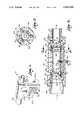
- FIG. 1is a perspective view of a binary gas monitoring device constructed according to the present invention
- FIG. 2is a cross sectional view taken through the transducer of the gas monitoring device
- FIG. 3is a sectional view taken generally along line 3--3 of FIG. 2 in the direction of the arrows;
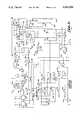
- FIG. 4is a block diagram of the electronic circuitry in the gas monitoring device
- FIG. 5is a schematic diagram of the circuitry
- FIG. 6is a diagramatic view of the waveforms at various parts of the circuitry.
- numeral 10generally designates a gas monitoring device constructed in accordance with the present invention and suitable for use in monitoring the relative concentration in a binary gas such as air (which is predominately nitrogen and oxygen).
- the gas monitoring device 10has a body 12 which houses an acoustical transducer and electronic circuitry which will be described in more detail.
- the transduceris housed within the upper portion of the body 12, while the electronics are housed within the lower portion of the body.
- the lower portion of the bodyincludes a front face 14 having a liquid crystal display (LCD) 16, an LED alarm indicator 17, an off switch 18, an audio alarm 19, an on switch 20, a low oxygen level adjustment switch 22 and a high level adjustment switch 24.
- LCDliquid crystal display
- the switches 18-24are membrane type switches. From each side of body 12 protrudes the edge of a thumbwheel adjustment control. Left hand control 25a sets the low alarm limit while switch 22 is depressed to reveal the value of the alarm setting, and right hand switch 25b sets the high alarm limit while switch 24 is depressed for the same purpose.
- the acoustical transducerincludes a cylindrical body 26 which may be constructed of a suitable plastic material. Glued or otherwise secured to the opposite ends of the body 26 are end caps 27 and 28. Fittings 29 and 30 are pressed into the end caps 27 and 28 and may be mated with standard ventilator ports in order to connect the transducer in a ventilator line. O rings 32 provide seals between the fittings and the end caps 28.
- a smaller tube or cylinder 34which is spaced inwardly from the inside wall of body 26 by two sets of spacers 36.
- Each set of spacers 36includes three spacers which are spaced apart 120° circumferentially and which locate the inner cylinder 34 in a coaxial relationship with the body 26.
- the spacers 36 in the two sets of spacersare located near the opposite ends of the inner cylinder 34.
- the opposite ends of cylinder 34are closed by dome shaped end caps 38 which maintain the turbulence of the gas that is being analyzed within acceptable limits.
- the wall of cylinder 34is provided with a plurality of inlet ports 40a which permit the gas to flow into the cylinder 34 and a plurality of outlet ports 40b which permit the gas to flow back out of the cylinder.
- the ports 40a and 40bare located near the opposite ends of cylinder 34 and spaced apart circumferentially around the cylinder.
- An acoustic transmitter 42is mounted within cylinder 34 at one end and includes a transmitting crystal 44.
- An acoustic receiver 46is mounted in the opposite end of cylinder 34 and is equipped with a receiving crystal 48.
- the crystals 44 and 48are preferably a matched pair of piezoelectric crystals which are mechanically resonant at 25 kHz. It should be noted that transmitting and receiving elements having other resonant frequencies can be used if desired.
- the spacing between the transmitter 44 and receiver 48is 1.50 inches. This distance has been selected because with air at 25° C. and with sound waves having a frequency of 25 kHz, 1.50 inches is approximately 2.75 times the wavelength or 90° shy of three wavelengths.
- the total wavelength shift from 0 to 100% oxygen (with a mixture of nitrogen and oxygen)is 0.157 wavelength, or a total phase shift of 20°.
- a pulse amplitude of 2.5 volts(as will be explained more fully), a full scale signal span of 278 mv results, and this has proven to be an adequate signal.
- the inside surface of cylinder 34is lined with an acoustic open cell foam 50 in order to minimize the reflection of sound waves from the inner cylinder wall.
- a temperature sensor 52which may be a commercially available electronic component sold by National Semiconductor under the designation LM34.
- the temperature sensor 52is preferably laser trimmed so that it provides a consistent output signal having a linear slope of +10 millivolts/° F.
- Electrical poweris supplied to the transmitter 44, the receiver 48 and the temperature sensor 52 by small wires 54 which extend through the wall of the outer body 26, through the annular space that is presented between body 26 and cylinder 34, and through the wall of cylinder 34 and the acoustical lining 50.
- Suitable sealing compound 56is used to seal the opening through which the wires extend into the outer body 26.
- This interior of cylinder 34presents a sample chamber 57 within the lining 50.
- a 25 kHz crystal controlled clock 58provides a clock signal to the LCD 16 and for the rest of the system as well.
- the 25 kHz clock signalis applied to serially arranged counting circuits 60 and 62 and also as one input to an AND gate 64.
- the output signal from the first counting circuit 60is applied as a 2.5 kHz signal to one input of an AND gate 66 which controls an audible alarm 68.
- the first counting circuitalso supplies one input to another AND gate 70.
- the second input to each of the gates 64 and 70is supplied by the second counting circuit 62.
- the output from gate 64is conditioned by buffer circuitry 72 and is provided to the transmitter 42 as a ten cycle burst of 25 kHz square waves every four milliseconds.
- Transmitter 42is damped by the very low impedance of buffer 72. This signal energizes the acoustical transmitter 42 which then applies corresponding bursts of acoustic waves that are picked up by the receiver 46.
- the electrical output signal from the receiver 46is partially damped by a resistor 74 and is amplified and inverted in a zero crossing inverting comparator 76.
- the output signal from circuit 76forms one input to an AND gate 78, the other input of which is supplied by gate 70 representing the tenth pulse that is transmitted by the transmitter 42. Consequently, the output signal from gate 78 is a signal that represents an isolation of the seventh pulse which is received by the receiver 46.
- the output signal from gate 78is applied to a phase discriminator 80 (which may be a flip flop circuit).
- the output signal from gate 70is also applied to the phase discriminator 80 which measures the phase difference between the signals from gates 70 and 78 to provide a measure of the transit time of the acoustical waves and thus a measure of the percentage of oxygen in the oxygen/nitrogen gas mixture between the transmitter 42 and receiver 46.
- the gas monitoring deviceis a battery operated instrument, and it is necessary to standardize the amplitude of the output signal from the phase discriminator 80. This is accomplished by a precision shunt regulator 82 which clips the output signal from the phase discriminator 80 to a 2.5 volt signal 83 at the output of a buffer 84 that receives the output signal from the phase discriminator 80. Therefore, 2.5 volt signal 83 occurs only once every 100th cycle from the clock circuit 58.
- the 2.5 volt signal 83is applied to a sample and hold circuit 86 along with the output signal from the phase discriminator 80.
- the sample and hold circuit 86has a controlled leakage and thereby acts as a pulse averaging (pulsewidth-to-voltage) discriminator.
- the sample-and-hold circuitthus provides an output analog DC signal that is proportional to the transit time of the acoustic signal, and the transit time is in turn proportional to the mean molecular weight of the gas mixture.
- the output signal from circuit 86is thus indicative of the relative proportions of the two known gases in the mixture.
- the sample and hold circuit 86also acts as an amplifier which brings the repeatable and mathematically predictable temperature coefficient of -3.628 mv/° F. up to -10 mv/° F. which matches the +10 mv/° F. characteristic of the temperature sensor 52.
- the output signals from the temperature sensor 52 and the sample and hold circuit 86are added together in an adder circuit 88, thus totally canceling the effects of temperature changes.
- An amplifier 90removes the DC offset signal and provides both scale and span adjustments.
- the output signal from the amplifier 90is thus a temperature compensated analog of the oxygen concentration in the oxygen/nitrogen gas mixture having a span of from 0 volts (pure nitrogen) to 1 volt (pure oxygen.)
- the scaleis linear.
- the 0-1 volt output from the amplifier 90is applied to the LCD 16 and provides a three digit readout of the percent of oxygen in the mixture.
- a peak detector 92adjusts the 2.5 signal 83 to a constant and stable reference voltage of 2.18 volts which is applied to a low battery comparator 94 and, through potentiometers 96 and 98, to respective comparators 100 and 102.
- the output signal from amplifier 90supplies the other input to each comparator 100 and 102.
- the second input to comparator 94is supplied by a battery 104, and comparator 94 supplies the LCD 16 with a signal in the event that the battery charge drops below a preselected level. The LCD 16 then displays a "low bat" indication on the face of the instrument.
- the potentiometer 96is used to set the high limit for the oxygen concentration, and its setting is made available to the LCD 16 through switch 24. When switch 24 is depressed, the high oxygen limit is displayed by the LCD 16. Similarly, switch 22 makes available to the LCD the low oxygen limit which is set by the other potentiometer 98. When switch 22 is depressed, the low oxygen setting is displayed by the LCD 16.
- An out of limit alarm 106is activated whenever the output signal from amplifier 90 is above the high oxygen limit set by potentiometer 96 or below the low oxygen alarm limit set by potentiometer 98. Then, the alarm LED 17 is energized, and the audible alarm 19 is energized at the frequency of the output from the first counting circuit 60 (2.5 kHz).
- FIG. 5is a schematic diagram of the circuitry which is shown in block diagram form in FIG. 4.
- the 25 kHz crystal controlled square wave oscillator 58serves as the master clock and may be either self contained or, as shown, located within the LCD display circuitry.
- the clock signalis applied to the first counter 60 and also to gate 64.
- the output signal from the second counter 62is applied as the other input to gate 64 and also as one input to gate 70, the other input of which comes from the first counter 60.
- the output signal from the first counter 60is a 2.5 kHz square wave which is applied to gate 66 and used to control the frequency of the audio alarm 19.
- the output signal from the second counter 62is high during ten cycles (400 microseconds) of the clock 58, and it operates on a duty cycle of 1:10 (every 4 milliseconds).
- the output signal from gate 64drives three parallel connected noninverting buffers 72a which collectively form the buffer 72 that excites the transmitter 42.
- the combined output impedance of the buffers 72aclosely matches that of the transmitter 42 and thus damps the transmitter when each pulse burst ceases.
- the output signal from gate 70is a pulse that is commensurate with the tenth cycle in each burst of ten transmitted pulses.
- the spacing between the transmitter 44 and receiver 48(2.75 wavelengths) imposes a delay of 110 microseconds, so that the seventh pulse in each pulse burst is received by the inverting comparator 76 20 microseconds after the beginning of the tenth transmitted pulse.
- signals commensurate with the tenth transmitted pulse and the seventh received pulseare applied to gate 78, the output of which is differentiated by a circuit formed by capacitor 108 and resistor 110 and applied to a noninverting buffer 112.
- the output from buffer 112is applied through a diode 114 to the flip flop which forms the phase discriminator 80.
- the output signal from gate 70is differentiated by a circuit formed by capacitor 116 and resistor 118 and is then applied to a noninverting buffer 120 and through diode 122 to the phase discriminator 80.
- the phase comparison between the tenth transmitted pulse and the seventh received pulseis made on a 100:1 duty cycle, thus minimizing current drain and assuring that there is sufficient quiescent time between successive bursts of pulses to allow full dissipation of reverberations and other transients.
- the output from the flip flop circuit 80is a rectangular pulse generated every four milliseconds, and the width of each pulse varies with the transit time of the selected ultrasound pulse.
- the precision shunt regulator 82clips the output pulse from buffer 84 to a constant amplitude of 2.5 volts over a battery range down to 4 volts, thus eliminating error as the 6 volt battery decays with age.
- the peak detector 92is formed by a diode 124, a capacitor 126 and an operational amplifier (op amp) 128, and the output signal from the op amp 128 is at a constant level of 2.18 volts which is applied to the low battery comparator 94.
- the voltage of the battery 104is applied through a voltage divider formed by resistors 130 and 132 as the other input to comparator 94, and a low battery signal is applied by comparator 94 to the display circuitry 16 whenever the battery voltage drops below a level of 4.3 volts.
- the voltage drop from 2.5 volts to 2.18 voltsresults from the forward junction drop of the diode 124.
- the sample-and-hold circuit 86is formed by an analog switch 134, resistors 136 and 138, a capacitor 140, and an op - amp 142.
- the op amp 142applies its output signal to the adder circuit 88 formed by resistors 144 and 146.
- the other input to the adder circuitis applied by the temperature sensor 52.
- sensor 52As previously indicated, sensor 52 generates a voltage of +10 mv/° F.
- the demodulated signalcontains a temperature error of -3.628 mv/° F.
- the op amp 142amplifies the temperature error to a level of -10 mv/° F. in order to cancel the +10 mv/° F. signal from the sensor 52 in the adder circuit 88 so that the effects of temperature are compensated for completely.
- the output signal from the adder circuit 88is applied to the amplifier circuit 90 which includes a comparator 148 and a pair of potentiometers 150 and 152.
- the 2.18 volt reference signal from op amp 128is also applied to the potentiometer 152, as well as to the high and low alarm setting potentiometers 96 and 98 respectively.
- the output signal from the amplifier circuit 90is applied on line 154 as an analog voltage that represents the percentage of oxygen in the oxygen/nitrogen gas mixture that is being analyzed.
- Line 154also connects with comparators 100 and 102 and through an analog switch 156 with an op amp 158.
- the output from comparator 158is applied to the display circuitry 16 which then generates a digital readout displaying the percentage of oxygen in the mixture.
- transistor 162When the on switch 20 is depressed, transistor 162 is conductive and applies battery power to the entire circuit.
- transistor 162becomes nonconductive, and power to the circuit is removed.
- a corresponding analog switch 164closes, and the signal circuit from the low oxygen potentiometer 98 is then applied through switch 164 to the op amp 158.
- the output from an inverter 166is driven low through diode switch 22 and 168 to open switch 156.
- the transmitter 44is excited at its resonant frequency of 25 kHz and emits successive bursts of acoustic waves, each containing ten consecutive pulses as indicated by the pulses identified by numeral 174 in FIG. 6.
- the quiescent time between the successive bursts of pulsesis long enough to assure that all reverberations and transients have dissipated before the initiation of each following burst of pulses, and this avoids standing waves that can interfere with proper operation of the device.
- the acoustic wavesare received by the receiver 48, following the transit time from the transmitter to the receiver, and the receiver 48 applies to comparator 76 an electrical signal which represents the acoustic energy it receives.
- the waveform which is input to comparator 76is shown in FIG. 6 and identified by numeral 176.
- the signal 176is amplified in the zero crossing inverting comparator 76 such that the output from comparator 76 is a square wave signal identified by the pulses 178 in FIG. 6.
- the output signal from gate 70represents the tenth transmitted pulse, as indicated by the pulse identified by numeral 180 in FIG. 6.
- Pulse 180is combined in gate 78 with the output from comparator 76 to isolate the seventh received pulse, as indicated by pulse 182 in FIG. 6.
- phase difference between pulses 180 and 182is measured in the phase discriminator provided by flip flop 80 and produces an output signal represented by pulse 184 in FIG. 6.
- the pulse 184is clipped to a 2.5 volt amplitude, as indicated by pulse 186 which is provided by the precision shunt regulator 82.
- Pulse 186occurs only once every 100th cycle of the clock, which requires the use of a sample-and-hold circuit 86, together with a controlled leakage to provide pulsewidth-to-voltage conversion.
- the output from the sample and hold circuit 86thus provides an output analog DC signal that is proportional to the transit time of the acoustic signal, and this transit time is in turn proportional to the mean molecular weight of the gas mixture so that it provides an identification of the relative proportion of the two gases contained in the air (which is considered to be a binary mixture of oxygen and nitrogen), or any other binary gas mixture which is being monitored.
- the high and low alarm points for the oxygenare set by adjusting potentiometers 98 and 96, respectively, and the value that is selected is displayed on the LCD 16 by depressing the corresponding membrane switch 22 or 24. It is again pointed out that when neither switch 22 or 24 is depressed, the LCD 16 displays the percent oxygen in the gas mixture that is being analyzed. If the oxygen content mixture is below the low alarm limit or above the high alarm limit, the audio alarm 19 generates an audio alarm signal and the LED 17 is energized to provide a visual alarm signal on the face of the instrument.
- the physical construction of the transduceralso adds to the accuracy and reliability of the instrument.
- the coaxial arrangement of body 26 and cylinder 34is advantageous in several respects. First, it assures that the gas flow through the sample chamber 57 is gentle and thus avoids the possible error that can be caused by high velocity gas flow. Secondly, it eliminates the possibility of a pressure differential between the inside and outside of the sample chamber that could alter the spacing and orientation of the components enough to cause a slight error. Finally, the temperature of the sample gas can be measured more accurately because the sensor 52 is in direct contact with the sample gas and effective thermal barriers are provided by body 26, cylinder 34, lining 50 and especially by the sample gas itself which flows in gently from the annular space between body 26 and cylinder 34.
Landscapes
- Physics & Mathematics (AREA)
- Acoustics & Sound (AREA)
- Health & Medical Sciences (AREA)
- Life Sciences & Earth Sciences (AREA)
- Chemical & Material Sciences (AREA)
- Analytical Chemistry (AREA)
- Biochemistry (AREA)
- General Health & Medical Sciences (AREA)
- General Physics & Mathematics (AREA)
- Immunology (AREA)
- Pathology (AREA)
- Investigating Or Analyzing Materials By The Use Of Ultrasonic Waves (AREA)
Abstract
Description
Claims (16)
Priority Applications (1)
| Application Number | Priority Date | Filing Date | Title |
|---|---|---|---|
| US07/424,931US5060506A (en) | 1989-10-23 | 1989-10-23 | Method and apparatus for monitoring the content of binary gas mixtures |
Applications Claiming Priority (1)
| Application Number | Priority Date | Filing Date | Title |
|---|---|---|---|
| US07/424,931US5060506A (en) | 1989-10-23 | 1989-10-23 | Method and apparatus for monitoring the content of binary gas mixtures |
Publications (1)
| Publication Number | Publication Date |
|---|---|
| US5060506Atrue US5060506A (en) | 1991-10-29 |
Family
ID=23684484
Family Applications (1)
| Application Number | Title | Priority Date | Filing Date |
|---|---|---|---|
| US07/424,931Expired - LifetimeUS5060506A (en) | 1989-10-23 | 1989-10-23 | Method and apparatus for monitoring the content of binary gas mixtures |
Country Status (1)
| Country | Link |
|---|---|
| US (1) | US5060506A (en) |
Cited By (105)
| Publication number | Priority date | Publication date | Assignee | Title |
|---|---|---|---|---|
| US5247826A (en)* | 1992-11-12 | 1993-09-28 | Devilbiss Health Care, Inc. | Gas concentration and/or flow sensor |
| US5313820A (en)* | 1989-11-30 | 1994-05-24 | Puritan Bennett Corporation | Ultrasonic gas measuring device |
| US5351522A (en)* | 1993-11-02 | 1994-10-04 | Aequitron Medical, Inc. | Gas sensor |
| US5392635A (en)* | 1993-12-30 | 1995-02-28 | At&T Corp. | Acoustic analysis of gas mixtures |
| USD360841S (en) | 1994-06-27 | 1995-08-01 | Stevens John J | Gas flow meter |
| US5467637A (en)* | 1992-12-24 | 1995-11-21 | Canon Kabushiki Kaisha | Method of measuring gas purity information, chamber unit and exposure unit using the method and a device production method |
| US5524477A (en)* | 1993-11-29 | 1996-06-11 | Leybold Inficon Inc. | Quantitative determination of air present in refrigerant sample by measurement of pressure coefficient of resonance frequency |
| US5528924A (en)* | 1993-11-29 | 1996-06-25 | Leybold Inficon Inc. | Acoustic tool for analysis of a gaseous substance |
| US5581014A (en)* | 1995-04-05 | 1996-12-03 | Douglas; David W. | Method and apparatus for acoustic analysis of binary gas mixtures with continuous self-calibration |
| WO1996029575A3 (en)* | 1995-03-13 | 1996-12-05 | Honeywell Inc | Low power signal processing and measurement apparatus |
| US5625140A (en)* | 1995-12-12 | 1997-04-29 | Lucent Technologies Inc. | Acoustic analysis of gas mixtures |
| US5627323A (en)* | 1995-05-25 | 1997-05-06 | Stern; Michael | Ultrasonic binary gas measuring device |
| US5697346A (en)* | 1993-05-28 | 1997-12-16 | Servojet Products International | Method for using sonic gas-fueled internal combustion engine control system |
| US5768937A (en)* | 1996-11-13 | 1998-06-23 | Leybold Inficon, Inc. | Acoustic sensor for in-line continuous monitoring of gasses |
| US5792665A (en)* | 1996-05-29 | 1998-08-11 | Morrow, Iii; Donald W. | Oxygen sensing method and hand held analyzer therefore |
| US5836200A (en)* | 1993-08-09 | 1998-11-17 | Uhp Corp. | Cell for measuring acoustical properties of fluid samples under high pressure |
| DE19745954A1 (en)* | 1997-10-17 | 1999-04-22 | Bernd Horst Dr Meier | Monitoring gas mixture compositions using musical instrument sounds to give oscillation in gas as oscillation frequency changes |
| US5900552A (en)* | 1997-03-28 | 1999-05-04 | Ohmeda Inc. | Inwardly directed wave mode ultrasonic transducer, gas analyzer, and method of use and manufacture |
| WO1999032236A1 (en)* | 1997-12-18 | 1999-07-01 | Fraunhofer-Gesellschaft zur Förderung der angewandten Forschung e.V. | Piezoelectric transducer with a temperature-sensitive component |
| WO1999067629A1 (en)* | 1998-06-24 | 1999-12-29 | Lattice Intellectual Property Limited | Measuring the speed of sound of a gas |
| US6277645B1 (en) | 1998-08-03 | 2001-08-21 | James R. Mault | Method and apparatus for respiratory gas analysis employing measurement of expired gas mass |
| US6309360B1 (en) | 1997-03-17 | 2001-10-30 | James R. Mault | Respiratory calorimeter |
| US6378372B1 (en) | 2000-05-17 | 2002-04-30 | Lawrence J. Karr | Acoustic resonance analysis of gas mixtures |
| US6402698B1 (en) | 1998-02-05 | 2002-06-11 | James R. Mault | Metabolic calorimeter employing respiratory gas analysis |
| US6406435B1 (en) | 1998-11-17 | 2002-06-18 | James R. Mault | Method and apparatus for the non-invasive determination of cardiac output |
| US6468222B1 (en) | 1999-08-02 | 2002-10-22 | Healthetech, Inc. | Metabolic calorimeter employing respiratory gas analysis |
| US6478736B1 (en) | 1999-10-08 | 2002-11-12 | Healthetech, Inc. | Integrated calorie management system |
| US6482158B2 (en) | 2000-05-19 | 2002-11-19 | Healthetech, Inc. | System and method of ultrasonic mammography |
| US20030023181A1 (en)* | 2001-07-26 | 2003-01-30 | Mault James R. | Gas analyzer of the fluorescent-film type particularly useful for respiratory analysis |
| US6517496B1 (en) | 1999-05-10 | 2003-02-11 | Healthetech, Inc. | Airway-based cardiac output monitor and methods for using same |
| US20030065274A1 (en)* | 1999-08-02 | 2003-04-03 | Mault James R. | Method of respiratory gas analysis using a metabolic calorimeter |
| WO2003037786A1 (en)* | 2001-10-30 | 2003-05-08 | Teijin Limited | Oxygen enriching device |
| US6572561B2 (en) | 1998-01-16 | 2003-06-03 | Healthetech, Inc. | Respiratory calorimeter |
| US20030105407A1 (en)* | 2001-11-30 | 2003-06-05 | Pearce, Edwin M. | Disposable flow tube for respiratory gas analysis |
| US20030150262A1 (en)* | 2000-03-14 | 2003-08-14 | Wei Han | Acoustic sensor for fluid characterization |
| US6607387B2 (en) | 2000-10-30 | 2003-08-19 | Healthetech, Inc. | Sensor system for diagnosing dental conditions |
| USD478660S1 (en) | 2002-07-01 | 2003-08-19 | Healthetech, Inc. | Disposable mask with sanitation insert for a respiratory analyzer |
| US6612306B1 (en) | 1999-10-13 | 2003-09-02 | Healthetech, Inc. | Respiratory nitric oxide meter |
| US6620106B2 (en) | 2000-09-29 | 2003-09-16 | Healthetech, Inc. | Indirect calorimetry system |
| US6629934B2 (en) | 2000-02-02 | 2003-10-07 | Healthetech, Inc. | Indirect calorimeter for medical applications |
| US20030208133A1 (en)* | 2000-06-07 | 2003-11-06 | Mault James R | Breath ketone analyzer |
| US20030210153A1 (en)* | 2002-05-13 | 2003-11-13 | Right Robert W. | Method and apparatus for adjusting audible and visual outputs of a mounted alarm device |
| US20040017014A1 (en)* | 2002-06-03 | 2004-01-29 | Teruhiko Tobinai | Rotary throttle valve carburetor |
| US20040050142A1 (en)* | 2000-10-09 | 2004-03-18 | Bertil Hok | Co2 sensor |
| US20040097822A1 (en)* | 2002-06-21 | 2004-05-20 | Nicolay Verwaltungs-Gmbh | Process and device for determination of a portion of a component of the air exhaled by a breathing living being characteristic of the metabolic function of such living being |
| US20040149285A1 (en)* | 2003-01-23 | 2004-08-05 | Maquet Critical Care Ab | Gas supply monitoring apparatus and method |
| US6790178B1 (en) | 1999-09-24 | 2004-09-14 | Healthetech, Inc. | Physiological monitor and associated computation, display and communication unit |
| US20040194539A1 (en)* | 2003-01-13 | 2004-10-07 | Gysling Daniel L. | Apparatus for measuring parameters of a flowing multiphase mixture |
| US20040220751A1 (en)* | 2003-03-27 | 2004-11-04 | Southwest Research Institute | Indirect measurement of diluents in a multi-component natural gas |
| US20050125170A1 (en)* | 2003-10-10 | 2005-06-09 | Gysling Daniel L. | Flow measurement apparatus having strain-based sensors and ultrasonic sensors |
| US6981947B2 (en) | 2002-01-22 | 2006-01-03 | University Of Florida Research Foundation, Inc. | Method and apparatus for monitoring respiratory gases during anesthesia |
| US7052854B2 (en) | 2001-05-23 | 2006-05-30 | University Of Florida Research Foundation, Inc. | Application of nanotechnology and sensor technologies for ex-vivo diagnostics |
| US7052468B2 (en) | 2001-05-24 | 2006-05-30 | University Of Florida Research Foundation, Inc. | Method and apparatus for detecting environmental smoke exposure |
| US20060150712A1 (en)* | 2005-01-13 | 2006-07-13 | Viktors Berstis | Method and apparatus for indicating a parameter of transmitted fluid |
| US7104963B2 (en) | 2002-01-22 | 2006-09-12 | University Of Florida Research Foundation, Inc. | Method and apparatus for monitoring intravenous (IV) drug concentration using exhaled breath |
| WO2006133738A1 (en) | 2005-06-17 | 2006-12-21 | Maquet Critical Care Ab | Reduction of pressure induced temperature influence on the speed of sound in a gas |
| US7291114B2 (en) | 2002-04-01 | 2007-11-06 | Microlife Corporation | System and method of determining an individualized drug administration protocol |
| US20070283748A1 (en)* | 2006-04-26 | 2007-12-13 | Tf Instruments, Inc. | Cell for measuring acoustical properties of a fluid sample |
| US7389187B2 (en) | 2003-01-13 | 2008-06-17 | Cidra Corporation | Apparatus and method using an array of ultrasonic sensors for determining the velocity of a fluid within a pipe |
| US7392193B2 (en) | 2000-06-16 | 2008-06-24 | Microlife Corporation | Speech recognition capability for a personal digital assistant |
| US7437946B2 (en) | 2005-05-27 | 2008-10-21 | Cidra Corporation | Apparatus and method for measuring a parameter of a multiphase flow |
| US20090065007A1 (en)* | 2007-09-06 | 2009-03-12 | Wilkinson William R | Oxygen concentrator apparatus and method |
| US7526966B2 (en) | 2005-05-27 | 2009-05-05 | Expro Meters, Inc. | Apparatus and method for measuring a parameter of a multiphase flow |
| DE202009003553U1 (en) | 2009-03-12 | 2009-08-27 | Habekost, Achim, Prof. Dr. | gas sensor |
| US7624651B2 (en) | 2006-10-30 | 2009-12-01 | Expro Meters, Inc. | Apparatus and method for attenuating acoustic waves in pipe walls for clamp-on ultrasonic flow meter |
| US7624650B2 (en) | 2006-07-27 | 2009-12-01 | Expro Meters, Inc. | Apparatus and method for attenuating acoustic waves propagating within a pipe wall |
| USD606655S1 (en) | 2008-06-27 | 2009-12-22 | Inova Labs, Llc | Portable oxygen concentrator |
| US7673526B2 (en) | 2006-11-01 | 2010-03-09 | Expro Meters, Inc. | Apparatus and method of lensing an ultrasonic beam for an ultrasonic flow meter |
| US7752918B2 (en) | 2006-11-09 | 2010-07-13 | Expro Meters, Inc. | Apparatus and method for measuring a fluid flow parameter within an internal passage of an elongated body |
| US7820108B2 (en) | 1999-11-08 | 2010-10-26 | University Of Florida Research Foundation, Inc. | Marker detection method and apparatus to monitor drug compliance |
| EP2280275A2 (en) | 2005-06-17 | 2011-02-02 | Maquet Critical Care AB | Reduction of pressure induced temperature influence on the speed of sound in a gas |
| US7914460B2 (en) | 2006-08-15 | 2011-03-29 | University Of Florida Research Foundation, Inc. | Condensate glucose analyzer |
| US8211035B2 (en) | 2002-01-22 | 2012-07-03 | University Of Florida Research Foundation, Inc. | System and method for monitoring health using exhaled breath |
| US8365724B2 (en) | 2009-12-29 | 2013-02-05 | General Electric Company | Medical vaporizer and method of control of a medical vaporizer |
| WO2013083978A1 (en) | 2011-12-06 | 2013-06-13 | The Technology Partnership Plc | Acoustic sensor |
| WO2013151447A1 (en) | 2012-04-05 | 2013-10-10 | Fisher & Paykel Healthcare Limited | Respiratory assistance apparatus |
| US8603228B2 (en) | 2010-09-07 | 2013-12-10 | Inova Labs, Inc. | Power management systems and methods for use in an oxygen concentrator |
| US8616207B2 (en) | 2010-09-07 | 2013-12-31 | Inova Labs, Inc. | Oxygen concentrator heat management system and method |
| US8641813B2 (en) | 2005-07-07 | 2014-02-04 | Expro Meters, Inc. | System and method for optimizing a gas/liquid separation process |
| US8752544B2 (en) | 2011-03-21 | 2014-06-17 | General Electric Company | Medical vaporizer and method of monitoring of a medical vaporizer |
| WO2016018919A1 (en)* | 2014-07-30 | 2016-02-04 | Towle Jonathan P | Ionic fluid antenna |
| US9440179B2 (en) | 2014-02-14 | 2016-09-13 | InovaLabs, LLC | Oxygen concentrator pump systems and methods |
| US9440180B2 (en) | 2012-10-12 | 2016-09-13 | Inova Labs, Llc | Oxygen concentrator systems and methods |
| US9440036B2 (en) | 2012-10-12 | 2016-09-13 | InovaLabs, LLC | Method and systems for the delivery of oxygen enriched gas |
| US9717876B2 (en) | 2012-10-12 | 2017-08-01 | Inova Labs, Inc. | Dual oxygen concentrator systems and methods |
| EP3148624A4 (en)* | 2014-05-27 | 2018-01-17 | Fisher&Paykel Healthcare Limited | Gases mixing and measuring for a medical device |
| WO2019110670A1 (en)* | 2017-12-05 | 2019-06-13 | Eaton Intelligent Power Limited | Gas sensor |
| WO2019139121A1 (en)* | 2018-01-12 | 2019-07-18 | 超音波工業株式会社 | Device for measuring speed-of-sound-related eigenvalue of gas, device for measuring component ratio of gas to which said device is applied, and global environment monitor device to which said devices are applied |
| US10610659B2 (en) | 2017-03-23 | 2020-04-07 | General Electric Company | Gas mixer incorporating sensors for measuring flow and concentration |
| US10709866B2 (en) | 2014-05-13 | 2020-07-14 | Fisher & Paykel Healthcare Limited | Usability features for respiratory humidification system |
| US10828482B2 (en) | 2013-12-20 | 2020-11-10 | Fisher & Paykel Healthcare Limited | Humidification system connections |
| US10946160B2 (en) | 2017-03-23 | 2021-03-16 | General Electric Company | Medical vaporizer with carrier gas characterization, measurement, and/or compensation |
| US10974015B2 (en) | 2012-03-15 | 2021-04-13 | Fisher & Paykel Healthcare Limited | Respiratory gas humidification system |
| US11029284B2 (en) | 2018-02-08 | 2021-06-08 | South Dakota Board Of Regents | Acoustic resonance chamber |
| US11129956B2 (en) | 2012-04-27 | 2021-09-28 | Fisher & Paykel Healthcare Limited | Usability features for respiratory humidification system |
| US11173272B2 (en) | 2014-05-02 | 2021-11-16 | Fisher & Paykel Healthcare Limited | Gas humidification arrangement |
| US11278689B2 (en) | 2014-11-17 | 2022-03-22 | Fisher & Paykel Healthcare Limited | Humidification of respiratory gases |
| US11324911B2 (en) | 2014-06-03 | 2022-05-10 | Fisher & Paykel Healthcare Limited | Flow mixers for respiratory therapy systems |
| US11351332B2 (en) | 2016-12-07 | 2022-06-07 | Fisher & Paykel Healthcare Limited | Sensing arrangements for medical devices |
| US11458274B2 (en) | 2016-05-03 | 2022-10-04 | Inova Labs, Inc. | Method and systems for the delivery of oxygen enriched gas |
| US11511069B2 (en) | 2013-09-13 | 2022-11-29 | Fisher & Paykel Healthcare Limited | Humidification system |
| US11559653B2 (en) | 2014-02-07 | 2023-01-24 | Fisher & Paykel Healthcare Limited | Respiratory humidification system |
| US11666720B2 (en) | 2015-12-02 | 2023-06-06 | Fisher & Paykel Healthcare Limited | Flow path sensing for flow therapy apparatus |
| US11801360B2 (en) | 2013-09-13 | 2023-10-31 | Fisher & Paykel Healthcare Limited | Connections for humidification system |
| DE102023133190A1 (en)* | 2023-11-28 | 2025-05-28 | Technische Universität Chemnitz, Körperschaft des öffentlichen Rechts | Sound speed sensor |
Citations (2)
| Publication number | Priority date | Publication date | Assignee | Title |
|---|---|---|---|---|
| US4630482A (en)* | 1985-06-17 | 1986-12-23 | John Traina | Method and apparatus for ultrasonic measurements of a medium |
| US4938066A (en)* | 1988-01-29 | 1990-07-03 | Xecutek Corporation | Ultrasonic apparatus for measuring the speed of sound in a gaseous medium |
- 1989
- 1989-10-23USUS07/424,931patent/US5060506A/ennot_activeExpired - Lifetime
Patent Citations (2)
| Publication number | Priority date | Publication date | Assignee | Title |
|---|---|---|---|---|
| US4630482A (en)* | 1985-06-17 | 1986-12-23 | John Traina | Method and apparatus for ultrasonic measurements of a medium |
| US4938066A (en)* | 1988-01-29 | 1990-07-03 | Xecutek Corporation | Ultrasonic apparatus for measuring the speed of sound in a gaseous medium |
Cited By (185)
| Publication number | Priority date | Publication date | Assignee | Title |
|---|---|---|---|---|
| US5313820A (en)* | 1989-11-30 | 1994-05-24 | Puritan Bennett Corporation | Ultrasonic gas measuring device |
| EP0597604A1 (en)* | 1992-11-12 | 1994-05-18 | Devilbiss Health Care, Inc. | Gas concentration and/or flow sensor |
| US5247826A (en)* | 1992-11-12 | 1993-09-28 | Devilbiss Health Care, Inc. | Gas concentration and/or flow sensor |
| US5467637A (en)* | 1992-12-24 | 1995-11-21 | Canon Kabushiki Kaisha | Method of measuring gas purity information, chamber unit and exposure unit using the method and a device production method |
| US5697346A (en)* | 1993-05-28 | 1997-12-16 | Servojet Products International | Method for using sonic gas-fueled internal combustion engine control system |
| US5836200A (en)* | 1993-08-09 | 1998-11-17 | Uhp Corp. | Cell for measuring acoustical properties of fluid samples under high pressure |
| US5351522A (en)* | 1993-11-02 | 1994-10-04 | Aequitron Medical, Inc. | Gas sensor |
| US5528924A (en)* | 1993-11-29 | 1996-06-25 | Leybold Inficon Inc. | Acoustic tool for analysis of a gaseous substance |
| US5524477A (en)* | 1993-11-29 | 1996-06-11 | Leybold Inficon Inc. | Quantitative determination of air present in refrigerant sample by measurement of pressure coefficient of resonance frequency |
| US5392635A (en)* | 1993-12-30 | 1995-02-28 | At&T Corp. | Acoustic analysis of gas mixtures |
| EP0661536B1 (en)* | 1993-12-30 | 2002-01-23 | AT&T Corp. | Acoustic analysis of gas mixtures |
| JP3104956B2 (en) | 1993-12-30 | 2000-10-30 | エイ・ティ・アンド・ティ・コーポレーション | Apparatus and method for acoustic analysis of mixed gas |
| US5501098A (en)* | 1993-12-30 | 1996-03-26 | At&T Corp. | Acoustic analysis of gas mixtures |
| USD360841S (en) | 1994-06-27 | 1995-08-01 | Stevens John J | Gas flow meter |
| WO1996029575A3 (en)* | 1995-03-13 | 1996-12-05 | Honeywell Inc | Low power signal processing and measurement apparatus |
| US5650571A (en)* | 1995-03-13 | 1997-07-22 | Freud; Paul J. | Low power signal processing and measurement apparatus |
| US5581014A (en)* | 1995-04-05 | 1996-12-03 | Douglas; David W. | Method and apparatus for acoustic analysis of binary gas mixtures with continuous self-calibration |
| US5627323A (en)* | 1995-05-25 | 1997-05-06 | Stern; Michael | Ultrasonic binary gas measuring device |
| US5625140A (en)* | 1995-12-12 | 1997-04-29 | Lucent Technologies Inc. | Acoustic analysis of gas mixtures |
| EP0779511A1 (en) | 1995-12-12 | 1997-06-18 | AT&T Corp. | Acoustic analysis of gas mixtures |
| US5792665A (en)* | 1996-05-29 | 1998-08-11 | Morrow, Iii; Donald W. | Oxygen sensing method and hand held analyzer therefore |
| US5768937A (en)* | 1996-11-13 | 1998-06-23 | Leybold Inficon, Inc. | Acoustic sensor for in-line continuous monitoring of gasses |
| US6616615B2 (en) | 1997-03-17 | 2003-09-09 | Healthetech, Inc. | Respiratory calorimeter |
| US6309360B1 (en) | 1997-03-17 | 2001-10-30 | James R. Mault | Respiratory calorimeter |
| US5900552A (en)* | 1997-03-28 | 1999-05-04 | Ohmeda Inc. | Inwardly directed wave mode ultrasonic transducer, gas analyzer, and method of use and manufacture |
| DE19745954A1 (en)* | 1997-10-17 | 1999-04-22 | Bernd Horst Dr Meier | Monitoring gas mixture compositions using musical instrument sounds to give oscillation in gas as oscillation frequency changes |
| WO1999032236A1 (en)* | 1997-12-18 | 1999-07-01 | Fraunhofer-Gesellschaft zur Förderung der angewandten Forschung e.V. | Piezoelectric transducer with a temperature-sensitive component |
| US6572561B2 (en) | 1998-01-16 | 2003-06-03 | Healthetech, Inc. | Respiratory calorimeter |
| US6402698B1 (en) | 1998-02-05 | 2002-06-11 | James R. Mault | Metabolic calorimeter employing respiratory gas analysis |
| US6645158B2 (en) | 1998-02-05 | 2003-11-11 | Healthetech, Inc. | Metabolic calorimeter employing respiratory gas analysis |
| AU746704B2 (en)* | 1998-06-24 | 2002-05-02 | Lattice Intellectual Property Limited | Measuring the speed of sound of a gas |
| WO1999067629A1 (en)* | 1998-06-24 | 1999-12-29 | Lattice Intellectual Property Limited | Measuring the speed of sound of a gas |
| US6481288B1 (en)* | 1998-06-24 | 2002-11-19 | Lattice Intellectual Property Ltd. | Measuring the speed of sound of a gas |
| US6277645B1 (en) | 1998-08-03 | 2001-08-21 | James R. Mault | Method and apparatus for respiratory gas analysis employing measurement of expired gas mass |
| US6506608B2 (en) | 1998-08-03 | 2003-01-14 | Healthetech, Inc. | Method and apparatus for respiratory gas analysis employing measurement of expired gas mass |
| US6406435B1 (en) | 1998-11-17 | 2002-06-18 | James R. Mault | Method and apparatus for the non-invasive determination of cardiac output |
| US6517496B1 (en) | 1999-05-10 | 2003-02-11 | Healthetech, Inc. | Airway-based cardiac output monitor and methods for using same |
| US20030167016A1 (en)* | 1999-05-10 | 2003-09-04 | Mault James R. | Airway-based cardiac output monitor and methods for using same |
| US6468222B1 (en) | 1999-08-02 | 2002-10-22 | Healthetech, Inc. | Metabolic calorimeter employing respiratory gas analysis |
| US20030065275A1 (en)* | 1999-08-02 | 2003-04-03 | Mault James R. | Metabolic calorimeter employing respiratory gas analysis |
| US20030065274A1 (en)* | 1999-08-02 | 2003-04-03 | Mault James R. | Method of respiratory gas analysis using a metabolic calorimeter |
| US6899683B2 (en) | 1999-08-02 | 2005-05-31 | Healthetech, Inc. | Metabolic calorimeter employing respiratory gas analysis |
| US6955650B2 (en) | 1999-08-02 | 2005-10-18 | Healthetech, Inc. | Metabolic calorimeter employing respiratory gas analysis |
| US6790178B1 (en) | 1999-09-24 | 2004-09-14 | Healthetech, Inc. | Physiological monitor and associated computation, display and communication unit |
| US6478736B1 (en) | 1999-10-08 | 2002-11-12 | Healthetech, Inc. | Integrated calorie management system |
| US6612306B1 (en) | 1999-10-13 | 2003-09-02 | Healthetech, Inc. | Respiratory nitric oxide meter |
| US7820108B2 (en) | 1999-11-08 | 2010-10-26 | University Of Florida Research Foundation, Inc. | Marker detection method and apparatus to monitor drug compliance |
| US6629934B2 (en) | 2000-02-02 | 2003-10-07 | Healthetech, Inc. | Indirect calorimeter for medical applications |
| US20030150262A1 (en)* | 2000-03-14 | 2003-08-14 | Wei Han | Acoustic sensor for fluid characterization |
| US6817229B2 (en)* | 2000-03-14 | 2004-11-16 | Halliburton Energy Services, Inc. | Acoustic sensor for fluid characterization |
| US6378372B1 (en) | 2000-05-17 | 2002-04-30 | Lawrence J. Karr | Acoustic resonance analysis of gas mixtures |
| US6482158B2 (en) | 2000-05-19 | 2002-11-19 | Healthetech, Inc. | System and method of ultrasonic mammography |
| US20030208133A1 (en)* | 2000-06-07 | 2003-11-06 | Mault James R | Breath ketone analyzer |
| US7392193B2 (en) | 2000-06-16 | 2008-06-24 | Microlife Corporation | Speech recognition capability for a personal digital assistant |
| US6620106B2 (en) | 2000-09-29 | 2003-09-16 | Healthetech, Inc. | Indirect calorimetry system |
| US20040050142A1 (en)* | 2000-10-09 | 2004-03-18 | Bertil Hok | Co2 sensor |
| US6843101B2 (en)* | 2000-10-09 | 2005-01-18 | Hoek Bertil | CO2 sensor |
| US6607387B2 (en) | 2000-10-30 | 2003-08-19 | Healthetech, Inc. | Sensor system for diagnosing dental conditions |
| US7052854B2 (en) | 2001-05-23 | 2006-05-30 | University Of Florida Research Foundation, Inc. | Application of nanotechnology and sensor technologies for ex-vivo diagnostics |
| US7052468B2 (en) | 2001-05-24 | 2006-05-30 | University Of Florida Research Foundation, Inc. | Method and apparatus for detecting environmental smoke exposure |
| US20030023181A1 (en)* | 2001-07-26 | 2003-01-30 | Mault James R. | Gas analyzer of the fluorescent-film type particularly useful for respiratory analysis |
| AU2002363201B2 (en)* | 2001-10-30 | 2007-03-22 | Teijin Limited | Oxygen enriching device |
| WO2003037786A1 (en)* | 2001-10-30 | 2003-05-08 | Teijin Limited | Oxygen enriching device |
| US20040060445A1 (en)* | 2001-10-30 | 2004-04-01 | Naotoshi Fujimoto | Oxygen enriching device |
| US6960246B2 (en) | 2001-10-30 | 2005-11-01 | Teijin Limited | Oxygen concentrating apparatus |
| US20030105407A1 (en)* | 2001-11-30 | 2003-06-05 | Pearce, Edwin M. | Disposable flow tube for respiratory gas analysis |
| US7104963B2 (en) | 2002-01-22 | 2006-09-12 | University Of Florida Research Foundation, Inc. | Method and apparatus for monitoring intravenous (IV) drug concentration using exhaled breath |
| US8211035B2 (en) | 2002-01-22 | 2012-07-03 | University Of Florida Research Foundation, Inc. | System and method for monitoring health using exhaled breath |
| US6981947B2 (en) | 2002-01-22 | 2006-01-03 | University Of Florida Research Foundation, Inc. | Method and apparatus for monitoring respiratory gases during anesthesia |
| US7291114B2 (en) | 2002-04-01 | 2007-11-06 | Microlife Corporation | System and method of determining an individualized drug administration protocol |
| US6927673B2 (en)* | 2002-05-13 | 2005-08-09 | Edwards Systems Technology, Inc. | Method and apparatus for adjusting audible and visual outputs of a mounted alarm device |
| WO2003098565A3 (en)* | 2002-05-13 | 2005-04-14 | Edwards Systems Technology Inc | Method and apparatus for adjusting audible and visual outputs of a mounted alarm device |
| US20030210153A1 (en)* | 2002-05-13 | 2003-11-13 | Right Robert W. | Method and apparatus for adjusting audible and visual outputs of a mounted alarm device |
| US20040017014A1 (en)* | 2002-06-03 | 2004-01-29 | Teruhiko Tobinai | Rotary throttle valve carburetor |
| US6991607B2 (en)* | 2002-06-21 | 2006-01-31 | Nicolay Verwaltungs-Gmbh | Process and device for measuring exhaled air to determine metabolic function of a living being |
| US20040097822A1 (en)* | 2002-06-21 | 2004-05-20 | Nicolay Verwaltungs-Gmbh | Process and device for determination of a portion of a component of the air exhaled by a breathing living being characteristic of the metabolic function of such living being |
| USD478660S1 (en) | 2002-07-01 | 2003-08-19 | Healthetech, Inc. | Disposable mask with sanitation insert for a respiratory analyzer |
| US20040194539A1 (en)* | 2003-01-13 | 2004-10-07 | Gysling Daniel L. | Apparatus for measuring parameters of a flowing multiphase mixture |
| US7096719B2 (en)* | 2003-01-13 | 2006-08-29 | Cidra Corporation | Apparatus for measuring parameters of a flowing multiphase mixture |
| US7389187B2 (en) | 2003-01-13 | 2008-06-17 | Cidra Corporation | Apparatus and method using an array of ultrasonic sensors for determining the velocity of a fluid within a pipe |
| US20040149285A1 (en)* | 2003-01-23 | 2004-08-05 | Maquet Critical Care Ab | Gas supply monitoring apparatus and method |
| US7010433B2 (en)* | 2003-03-27 | 2006-03-07 | Southwest Research Institute | Indirect measurement of diluents in a multi-component natural gas |
| WO2005022122A3 (en)* | 2003-03-27 | 2006-08-10 | Southwest Res Inst | Indirect measurement of diluents in a multi-component natural gas |
| US20040220751A1 (en)* | 2003-03-27 | 2004-11-04 | Southwest Research Institute | Indirect measurement of diluents in a multi-component natural gas |
| US7237440B2 (en) | 2003-10-10 | 2007-07-03 | Cidra Corporation | Flow measurement apparatus having strain-based sensors and ultrasonic sensors |
| US20050125170A1 (en)* | 2003-10-10 | 2005-06-09 | Gysling Daniel L. | Flow measurement apparatus having strain-based sensors and ultrasonic sensors |
| US7430924B2 (en) | 2003-10-10 | 2008-10-07 | Expro Meters Inc. | Flow measurement apparatus having strain-based sensors and ultrasonic sensors |
| US20060150712A1 (en)* | 2005-01-13 | 2006-07-13 | Viktors Berstis | Method and apparatus for indicating a parameter of transmitted fluid |
| US7093479B2 (en)* | 2005-01-13 | 2006-08-22 | International Business Machines Corporation | Method and apparatus for indicating a parameter of transmitted fluid |
| US7437946B2 (en) | 2005-05-27 | 2008-10-21 | Cidra Corporation | Apparatus and method for measuring a parameter of a multiphase flow |
| US7526966B2 (en) | 2005-05-27 | 2009-05-05 | Expro Meters, Inc. | Apparatus and method for measuring a parameter of a multiphase flow |
| EP3045905A1 (en) | 2005-06-17 | 2016-07-20 | Maquet Critical Care AB | Reduction of pressure induced temperature influence on the speed of sound in a gas |
| US8381574B2 (en) | 2005-06-17 | 2013-02-26 | Maquet Critical Care Ab | Reduction of pressure induced temperature influence on the speed of sound in a gas |
| US20090314058A1 (en)* | 2005-06-17 | 2009-12-24 | Erik Cardelius | Reduction of pressure induced temperature influence on the speed of sound in a gas |
| WO2006133738A1 (en) | 2005-06-17 | 2006-12-21 | Maquet Critical Care Ab | Reduction of pressure induced temperature influence on the speed of sound in a gas |
| US7784327B2 (en) | 2005-06-17 | 2010-08-31 | Maquet Critical Care Ab | Reduction of pressure induced temperature influence on the speed of sound in a gas |
| EP2280275A2 (en) | 2005-06-17 | 2011-02-02 | Maquet Critical Care AB | Reduction of pressure induced temperature influence on the speed of sound in a gas |
| US8641813B2 (en) | 2005-07-07 | 2014-02-04 | Expro Meters, Inc. | System and method for optimizing a gas/liquid separation process |
| US20070283748A1 (en)* | 2006-04-26 | 2007-12-13 | Tf Instruments, Inc. | Cell for measuring acoustical properties of a fluid sample |
| US7624650B2 (en) | 2006-07-27 | 2009-12-01 | Expro Meters, Inc. | Apparatus and method for attenuating acoustic waves propagating within a pipe wall |
| US7914460B2 (en) | 2006-08-15 | 2011-03-29 | University Of Florida Research Foundation, Inc. | Condensate glucose analyzer |
| US7624651B2 (en) | 2006-10-30 | 2009-12-01 | Expro Meters, Inc. | Apparatus and method for attenuating acoustic waves in pipe walls for clamp-on ultrasonic flow meter |
| US7673526B2 (en) | 2006-11-01 | 2010-03-09 | Expro Meters, Inc. | Apparatus and method of lensing an ultrasonic beam for an ultrasonic flow meter |
| US7752918B2 (en) | 2006-11-09 | 2010-07-13 | Expro Meters, Inc. | Apparatus and method for measuring a fluid flow parameter within an internal passage of an elongated body |
| US20110030684A1 (en)* | 2007-09-06 | 2011-02-10 | Inova Labs, Inc. | Oxygen concentrator apparatus and method having flow restricted coupling of the canisters |
| US8794237B2 (en) | 2007-09-06 | 2014-08-05 | Inova Labs, Inc. | Oxygen concentrator apparatus and method having flow restricted coupling of the canisters |
| US20110030685A1 (en)* | 2007-09-06 | 2011-02-10 | Wilkinson William R | Oxygen concentrator apparatus and method of delivering pulses of oxygen |
| US20110030686A1 (en)* | 2007-09-06 | 2011-02-10 | Inova Labs, Inc. | Oxygen concentrator apparatus and method having variable operation modes |
| US20110030687A1 (en)* | 2007-09-06 | 2011-02-10 | Inova Labs, Inc. | Oxygen concentrator apparatus and method with an oxygen assisted venting system |
| US20110030689A1 (en)* | 2007-09-06 | 2011-02-10 | Inova Labs, Inc. | Oxygen concentrator apparatus and method having an ultrasonic detector |
| US9956370B2 (en) | 2007-09-06 | 2018-05-01 | Inova, Labs, LLC. | Oxygen concentrator apparatus and method having flow restricted coupling of the canisters |
| US9649464B2 (en) | 2007-09-06 | 2017-05-16 | Inova Labs, Inc. | Oxygen concentrator apparatus and method having an ultrasonic detector |
| US9649465B2 (en) | 2007-09-06 | 2017-05-16 | Inova Labs, Inc. | Oxygen concentrator apparatus and method having variable operation modes |
| US20090065007A1 (en)* | 2007-09-06 | 2009-03-12 | Wilkinson William R | Oxygen concentrator apparatus and method |
| US8915248B2 (en) | 2007-09-06 | 2014-12-23 | Inova Labs, Inc. | Oxygen concentrator apparatus and method with an oxygen assisted venting system |
| USD606655S1 (en) | 2008-06-27 | 2009-12-22 | Inova Labs, Llc | Portable oxygen concentrator |
| DE202009003553U1 (en) | 2009-03-12 | 2009-08-27 | Habekost, Achim, Prof. Dr. | gas sensor |
| US8365724B2 (en) | 2009-12-29 | 2013-02-05 | General Electric Company | Medical vaporizer and method of control of a medical vaporizer |
| US8616207B2 (en) | 2010-09-07 | 2013-12-31 | Inova Labs, Inc. | Oxygen concentrator heat management system and method |
| US8603228B2 (en) | 2010-09-07 | 2013-12-10 | Inova Labs, Inc. | Power management systems and methods for use in an oxygen concentrator |
| US9586020B2 (en) | 2011-03-21 | 2017-03-07 | General Electric Company | Medical vaporizer and method of monitoring of a medical vaporizer |
| US8752544B2 (en) | 2011-03-21 | 2014-06-17 | General Electric Company | Medical vaporizer and method of monitoring of a medical vaporizer |
| WO2013083978A1 (en) | 2011-12-06 | 2013-06-13 | The Technology Partnership Plc | Acoustic sensor |
| US9869659B2 (en) | 2011-12-06 | 2018-01-16 | The Technology Partnership Plc. | Acoustic sensor |
| US10974015B2 (en) | 2012-03-15 | 2021-04-13 | Fisher & Paykel Healthcare Limited | Respiratory gas humidification system |
| US12350436B2 (en) | 2012-03-15 | 2025-07-08 | Fisher & Paykel Healthcare Limited | Respiratory gas humidification system |
| EP3446737A1 (en)* | 2012-04-05 | 2019-02-27 | Fisher & Paykel Healthcare Limited | Respiratory assistance apparatus |
| AU2018204819B2 (en)* | 2012-04-05 | 2020-02-20 | Fisher & Paykel Healthcare Limited | Respiratory assistance apparatus |
| EP3998097A1 (en)* | 2012-04-05 | 2022-05-18 | Fisher & Paykel Healthcare Limited | Respiratory assistance apparatus |
| AU2021221906B2 (en)* | 2012-04-05 | 2023-08-10 | Fisher & Paykel Healthcare Limited | Respiratory assistance apparatus |
| WO2013151447A1 (en) | 2012-04-05 | 2013-10-10 | Fisher & Paykel Healthcare Limited | Respiratory assistance apparatus |
| EP3915620A1 (en)* | 2012-04-05 | 2021-12-01 | Fisher & Paykel Healthcare Limited | Respiratory assistance apparatus |
| CN104602743B (en)* | 2012-04-05 | 2018-01-05 | 费雪派克医疗保健有限公司 | breathing assistance device |
| US10980967B2 (en) | 2012-04-05 | 2021-04-20 | Fisher & Paykel Healthcare Limited | Respiratory assistance apparatus |
| US12296103B2 (en) | 2012-04-05 | 2025-05-13 | Fisher & Paykel Healthcare Limited | Respiratory assistance apparatus |
| EP2833953A4 (en)* | 2012-04-05 | 2015-11-11 | Fisher & Paykel Healthcare Ltd | RESPIRATORY ASSISTANCE APPARATUS |
| CN107998495A (en)* | 2012-04-05 | 2018-05-08 | 费雪派克医疗保健有限公司 | Respiratory auxiliary system |
| CN104602743A (en)* | 2012-04-05 | 2015-05-06 | 费雪派克医疗保健有限公司 | breathing assistance device |
| US11918748B2 (en) | 2012-04-05 | 2024-03-05 | Fisher & Paykel Healthcare Limited | Respiratory assistance apparatus |
| EP4353291A3 (en)* | 2012-04-05 | 2024-06-05 | Fisher & Paykel Healthcare Limited | Respiratory assistance apparatus |
| US10357629B2 (en) | 2012-04-05 | 2019-07-23 | Fisher & Paykel Healthcare Limited | Respiratory assistance apparatus |
| JP2015512320A (en)* | 2012-04-05 | 2015-04-27 | フィッシャー アンド ペイケル ヘルスケア リミテッド | Respiratory device |
| US11878093B2 (en) | 2012-04-27 | 2024-01-23 | Fisher & Paykel Healthcare Limited | Usability features for respiratory humidification system |
| US11129956B2 (en) | 2012-04-27 | 2021-09-28 | Fisher & Paykel Healthcare Limited | Usability features for respiratory humidification system |
| US9717876B2 (en) | 2012-10-12 | 2017-08-01 | Inova Labs, Inc. | Dual oxygen concentrator systems and methods |
| US9440036B2 (en) | 2012-10-12 | 2016-09-13 | InovaLabs, LLC | Method and systems for the delivery of oxygen enriched gas |
| US11364359B2 (en) | 2012-10-12 | 2022-06-21 | Inova Labs, Inc. | Method and systems for the delivery of oxygen enriched gas |
| US9440180B2 (en) | 2012-10-12 | 2016-09-13 | Inova Labs, Llc | Oxygen concentrator systems and methods |
| US11684744B2 (en) | 2012-10-12 | 2023-06-27 | Inova Labs, Inc. | Method and systems for the delivery of oxygen enriched gas |
| US12053589B2 (en) | 2013-09-13 | 2024-08-06 | Fisher & Paykel Healthcare Limited | Humidification system |
| US11511069B2 (en) | 2013-09-13 | 2022-11-29 | Fisher & Paykel Healthcare Limited | Humidification system |
| US11801360B2 (en) | 2013-09-13 | 2023-10-31 | Fisher & Paykel Healthcare Limited | Connections for humidification system |
| US10828482B2 (en) | 2013-12-20 | 2020-11-10 | Fisher & Paykel Healthcare Limited | Humidification system connections |
| US11826538B2 (en) | 2013-12-20 | 2023-11-28 | Fisher & Paykel Healthcare Limited | Humidification system connections |
| US12397127B2 (en) | 2014-02-07 | 2025-08-26 | Fisher & Paykel Healthcare Limited | Respiratory humidification system |
| US11559653B2 (en) | 2014-02-07 | 2023-01-24 | Fisher & Paykel Healthcare Limited | Respiratory humidification system |
| US9440179B2 (en) | 2014-02-14 | 2016-09-13 | InovaLabs, LLC | Oxygen concentrator pump systems and methods |
| US11173272B2 (en) | 2014-05-02 | 2021-11-16 | Fisher & Paykel Healthcare Limited | Gas humidification arrangement |
| US11992622B2 (en) | 2014-05-13 | 2024-05-28 | Fisher & Paykel Healthcare Limited | Usability features for respiratory humidification system |
| US10709866B2 (en) | 2014-05-13 | 2020-07-14 | Fisher & Paykel Healthcare Limited | Usability features for respiratory humidification system |
| CN110393839A (en)* | 2014-05-27 | 2019-11-01 | 费雪派克医疗保健有限公司 | Gas mixing and measurement for medical device |
| EP3148624A4 (en)* | 2014-05-27 | 2018-01-17 | Fisher&Paykel Healthcare Limited | Gases mixing and measuring for a medical device |
| US11433210B2 (en) | 2014-05-27 | 2022-09-06 | Fisher & Paykel Healthcare Limited | Gases mixing and measuring for a medical device |
| US12053585B2 (en) | 2014-05-27 | 2024-08-06 | Fisher & Paykel Healthcare Limited | Gases mixing and measuring for a medical device |
| AU2015268171B2 (en)* | 2014-05-27 | 2020-05-07 | Fisher & Paykel Healthcare Limited | Gases mixing and measuring for a medical device |
| EP4235120A3 (en)* | 2014-05-27 | 2023-10-04 | Fisher & Paykel Healthcare Limited | Gases mixing and measuring for a medical device |
| US11712536B2 (en) | 2014-06-03 | 2023-08-01 | Fisher & Paykel Healthcare Limited | Flow mixers for respiratory therapy systems |
| US11324911B2 (en) | 2014-06-03 | 2022-05-10 | Fisher & Paykel Healthcare Limited | Flow mixers for respiratory therapy systems |
| WO2016018919A1 (en)* | 2014-07-30 | 2016-02-04 | Towle Jonathan P | Ionic fluid antenna |
| KR20170037611A (en)* | 2014-07-30 | 2017-04-04 | 조나단 피. 토우레 | Ionic fluid antenna |
| US10498018B2 (en)* | 2014-07-30 | 2019-12-03 | Jonathan P. Towle | Ionic fluid antenna |
| US11278689B2 (en) | 2014-11-17 | 2022-03-22 | Fisher & Paykel Healthcare Limited | Humidification of respiratory gases |
| US11666720B2 (en) | 2015-12-02 | 2023-06-06 | Fisher & Paykel Healthcare Limited | Flow path sensing for flow therapy apparatus |
| US11458274B2 (en) | 2016-05-03 | 2022-10-04 | Inova Labs, Inc. | Method and systems for the delivery of oxygen enriched gas |
| US11351332B2 (en) | 2016-12-07 | 2022-06-07 | Fisher & Paykel Healthcare Limited | Sensing arrangements for medical devices |
| US10946160B2 (en) | 2017-03-23 | 2021-03-16 | General Electric Company | Medical vaporizer with carrier gas characterization, measurement, and/or compensation |
| US10610659B2 (en) | 2017-03-23 | 2020-04-07 | General Electric Company | Gas mixer incorporating sensors for measuring flow and concentration |
| WO2019110670A1 (en)* | 2017-12-05 | 2019-06-13 | Eaton Intelligent Power Limited | Gas sensor |
| US11255774B2 (en) | 2017-12-05 | 2022-02-22 | Eaton Intelligent Power Limited | Gas sensor |
| WO2019139121A1 (en)* | 2018-01-12 | 2019-07-18 | 超音波工業株式会社 | Device for measuring speed-of-sound-related eigenvalue of gas, device for measuring component ratio of gas to which said device is applied, and global environment monitor device to which said devices are applied |
| US11029284B2 (en) | 2018-02-08 | 2021-06-08 | South Dakota Board Of Regents | Acoustic resonance chamber |
| US11796510B2 (en) | 2018-02-08 | 2023-10-24 | South Dakota Board Of Regents | Acoustic resonance chamber |
| DE102023133190A1 (en)* | 2023-11-28 | 2025-05-28 | Technische Universität Chemnitz, Körperschaft des öffentlichen Rechts | Sound speed sensor |
| EP4563951A1 (en) | 2023-11-28 | 2025-06-04 | Technische Universität Chemnitz Körperschaft des öffentlichen Rechts | Sound velocity sensor |
| DE102023133190B4 (en)* | 2023-11-28 | 2025-06-18 | Technische Universität Chemnitz, Körperschaft des öffentlichen Rechts | Sound speed sensor |
Similar Documents
| Publication | Publication Date | Title |
|---|---|---|
| US5060506A (en) | Method and apparatus for monitoring the content of binary gas mixtures | |
| US5351522A (en) | Gas sensor | |
| US5060514A (en) | Ultrasonic gas measuring device | |
| EP0100584B1 (en) | Ultrasonic flowmeter | |
| US4248087A (en) | System and method for determining fluid level in a container | |
| US4662212A (en) | Measuring instrument for concentration of gas | |
| Rooney | Determination of acoustic power outputs in the microwatt-milliwatt range | |
| EP0597604A1 (en) | Gas concentration and/or flow sensor | |
| US5581014A (en) | Method and apparatus for acoustic analysis of binary gas mixtures with continuous self-calibration | |
| EP1325319B1 (en) | Acoustic co2-sensor | |
| US5385069A (en) | Device for determining the volume of objects using a chamber with two resonators to compensate for temperature and humidity effects | |
| EP1205748A1 (en) | Acoustic gas analyser | |
| US4555932A (en) | Method and apparatus for assaying the purity of a gas | |
| US4380167A (en) | Apparatus and method for detecting a fraction of a gas | |
| US6820462B2 (en) | Acoustic gas monitor | |
| CA1249363A (en) | Biological fluid specific gravity monitor with ultrasonic sensor circuit | |
| Buess et al. | Design and construction of a pulsed ultrasonic air flowmeter | |
| US6079266A (en) | Fluid-level measurement by dynamic excitation of a pressure- and fluid-load-sensitive diaphragm | |
| US20040200266A1 (en) | Acoustic analysis of gas mixtures | |
| CN2100612U (en) | Sonar levelmeter | |
| SU700784A1 (en) | Acoustic level meter | |
| RU2210764C1 (en) | Procedure determining density of liquids and device for its implementation | |
| JPH0337522A (en) | Current meter | |
| JPS623379B2 (en) | ||
| SU605081A1 (en) | Method and apparatus for monitoring sheet material thickness |
Legal Events
| Date | Code | Title | Description |
|---|---|---|---|
| STCF | Information on status: patent grant | Free format text:PATENTED CASE | |
| AS | Assignment | Owner name:HEALTHDYNE TECHNOLOGIES, INC., GEORGIA Free format text:ASSIGNMENT OF ASSIGNORS INTEREST.;ASSIGNOR:HEALTHDYNE, INC.;REEL/FRAME:006505/0794 Effective date:19930412 | |
| AS | Assignment | Owner name:HEALTHDYNE TECHNOLOGIES, INC., GEORGIA Free format text:ASSIGNMENT OF ASSIGNORS INTEREST;ASSIGNOR:DOUGLAS, DAVID W.;REEL/FRAME:006528/0855 Effective date:19930421 | |
| AS | Assignment | Owner name:CONTINENTAL BANK, N.A., ILLINOIS Free format text:SECURITY INTEREST;ASSIGNOR:HEALTHDYNE TECHNOLOGIES, INC.;REEL/FRAME:006611/0362 Effective date:19930629 | |
| FEPP | Fee payment procedure | Free format text:PAT HLDR NO LONGER CLAIMS SMALL ENT STAT AS INDIV INVENTOR (ORIGINAL EVENT CODE: LSM1); ENTITY STATUS OF PATENT OWNER: LARGE ENTITY Free format text:PAYOR NUMBER ASSIGNED (ORIGINAL EVENT CODE: ASPN); ENTITY STATUS OF PATENT OWNER: LARGE ENTITY Free format text:PAYER NUMBER DE-ASSIGNED (ORIGINAL EVENT CODE: RMPN); ENTITY STATUS OF PATENT OWNER: LARGE ENTITY | |
| REFU | Refund | Free format text:REFUND PROCESSED. MAINTENANCE FEE HAS ALREADY BEEN PAID (ORIGINAL EVENT CODE: R160); ENTITY STATUS OF PATENT OWNER: LARGE ENTITY | |
| AS | Assignment | Owner name:BANK OF AMERICA NATIONAL TRUST AND SAVINGS ASSOCIA Free format text:AMENDED AND RESTATED PATENT AND TRADEMARK SECURITY AGREEMENT;ASSIGNOR:HEALTHDYNE TECHNOLOGIES, INC.;REEL/FRAME:007365/0425 Effective date:19941229 Owner name:HEALTHDYNE TECHNOLOGIES, INC., GEORGIA Free format text:RELEASE OF PATENT & TRADEMARK SECURITY AGREEMENT;ASSIGNOR:CONTINENTAL BANK, N.A.;REEL/FRAME:007365/0420 Effective date:19941229 | |
| FPAY | Fee payment | Year of fee payment:4 | |
| FPAY | Fee payment | Year of fee payment:8 | |
| AS | Assignment | Owner name:RESPIRONICS GEORGIA, INC., GEORGIA Free format text:CHANGE OF NAME;ASSIGNOR:HEALTHDYNE TECHNOLOGIES, INC.;REEL/FRAME:010579/0043 Effective date:19980421 | |
| FPAY | Fee payment | Year of fee payment:12 | |
| AS | Assignment | Owner name:RESPIRONICS, INC., PENNSYLVANIA Free format text:MERGER;ASSIGNOR:RESPIRONICS GEORGIA, INC.;REEL/FRAME:016735/0555 Effective date:20021216 | |
| AS | Assignment | Owner name:RIC INVESTMENTS, INC., DELAWARE Free format text:DIVIDEND FROM SUBSIDIARY TO PARENT;ASSIGNOR:RESPIRONICS, INC.;REEL/FRAME:016747/0220 Effective date:20020627 Owner name:RIC INVESTMENTS, LLC., DELAWARE Free format text:CHANGE OF NAME;ASSIGNOR:RIC INVESTMENTS, INC.;REEL/FRAME:016750/0202 Effective date:20040317 |