US5059185A - Safety needled medical devices - Google Patents
Safety needled medical devicesDownload PDFInfo
- Publication number
- US5059185A US5059185AUS07/162,569US16256988AUS5059185AUS 5059185 AUS5059185 AUS 5059185AUS 16256988 AUS16256988 AUS 16256988AUS 5059185 AUS5059185 AUS 5059185A
- Authority
- US
- United States
- Prior art keywords
- shield
- inner tube
- shield member
- hollow
- hollow body
- Prior art date
- Legal status (The legal status is an assumption and is not a legal conclusion. Google has not performed a legal analysis and makes no representation as to the accuracy of the status listed.)
- Expired - Fee Related
Links
- 239000008280bloodSubstances0.000claimsdescription30
- 210000004369bloodAnatomy0.000claimsdescription30
- 239000012530fluidSubstances0.000claimsdescription20
- 230000003247decreasing effectEffects0.000claimsdescription6
- 230000007423decreaseEffects0.000claimsdescription5
- 239000004033plasticSubstances0.000claimsdescription4
- 206010069803Injury associated with deviceDiseases0.000abstractdescription5
- 238000000034methodMethods0.000description11
- 238000004519manufacturing processMethods0.000description10
- 239000003814drugSubstances0.000description8
- 229940079593drugDrugs0.000description7
- 229940071643prefilled syringeDrugs0.000description6
- 238000002347injectionMethods0.000description5
- 239000007924injectionSubstances0.000description5
- 230000007246mechanismEffects0.000description5
- 230000008901benefitEffects0.000description4
- 208000012266Needlestick injuryDiseases0.000description3
- 230000009471actionEffects0.000description3
- 230000008859changeEffects0.000description3
- 210000005069earsAnatomy0.000description3
- 230000012953feeding on blood of other organismEffects0.000description3
- 239000007788liquidSubstances0.000description3
- 239000002184metalSubstances0.000description3
- 208000027418Wounds and injuryDiseases0.000description2
- 238000010276constructionMethods0.000description2
- 230000006378damageEffects0.000description2
- 230000001419dependent effectEffects0.000description2
- 201000010099diseaseDiseases0.000description2
- 208000037265diseases, disorders, signs and symptomsDiseases0.000description2
- 208000014674injuryDiseases0.000description2
- 238000001990intravenous administrationMethods0.000description2
- 239000000463materialSubstances0.000description2
- 230000013011matingEffects0.000description2
- 238000007789sealingMethods0.000description2
- 208000035473Communicable diseaseDiseases0.000description1
- 238000011109contaminationMethods0.000description1
- 230000008602contractionEffects0.000description1
- 238000005336crackingMethods0.000description1
- 230000002498deadly effectEffects0.000description1
- 239000011521glassSubstances0.000description1
- 230000036541healthEffects0.000description1
- 230000002452interceptive effectEffects0.000description1
- 238000005259measurementMethods0.000description1
- 238000002483medicationMethods0.000description1
- 238000012986modificationMethods0.000description1
- 230000004048modificationEffects0.000description1
- 239000002991molded plasticSubstances0.000description1
- 230000035515penetrationEffects0.000description1
- 230000001681protective effectEffects0.000description1
- 210000003462veinAnatomy0.000description1
- 230000000007visual effectEffects0.000description1
- 238000003466weldingMethods0.000description1
Images


Classifications
- A—HUMAN NECESSITIES
- A61—MEDICAL OR VETERINARY SCIENCE; HYGIENE
- A61M—DEVICES FOR INTRODUCING MEDIA INTO, OR ONTO, THE BODY; DEVICES FOR TRANSDUCING BODY MEDIA OR FOR TAKING MEDIA FROM THE BODY; DEVICES FOR PRODUCING OR ENDING SLEEP OR STUPOR
- A61M5/00—Devices for bringing media into the body in a subcutaneous, intra-vascular or intramuscular way; Accessories therefor, e.g. filling or cleaning devices, arm-rests
- A61M5/178—Syringes
- A61M5/31—Details
- A61M5/32—Needles; Details of needles pertaining to their connection with syringe or hub; Accessories for bringing the needle into, or holding the needle on, the body; Devices for protection of needles
- A61M5/3205—Apparatus for removing or disposing of used needles or syringes, e.g. containers; Means for protection against accidental injuries from used needles
- A61M5/321—Means for protection against accidental injuries by used needles
- A61M5/3243—Means for protection against accidental injuries by used needles being axially-extensible, e.g. protective sleeves coaxially slidable on the syringe barrel
Definitions
- the present inventiongenerally relates to improvements in safety needled medical devices which are designed to minimize the incidence of accidental pricking of the skin and resulting spread of infectious diseases by an exposed contaminated needle after use thereof.
- the disclosed devicesmay be used as blood collection tube holders, syringes with or without an attached needle, and prefilled syringes.
- the prior artdiscloses a number of devices which are arranged to shield the needle of the device after use, but none are as simple to manufacture, assemble, and use as the devices of the present invention.
- a benefit of the devices of the present inventionis that the devices require no change in the method of use or technique by medical personnel, i.e. the medical practioners will use the devices in the same way they previously used standard hypodermic syringes, IV catheters, and blood collection tube holders, except that after use they will move a shield to cover the exposed contaminated needle in a very easy, simple and straightforward manner.
- safety-needled syringessuch as are disclosed in U.S. Pat. Nos. 2,571,653 to Bastien, 4,026,287 to Haller, 4,425,120 to Sampson et al., 4,573,976 to Sampson et al., 4,631,057 to Mitchell, et al. 4,643,199 to Jennings, Jr. et al., 4,655,751 to Harbaugh, 4,666,435 to Braginetz, 4,681,567 to Masters et al.
- U.S. Pat. No. 4,655,751 to Harbaughrequires at least one slide groove to maintain the shield in the proper rotational axis and to thereby align a pair of ears on the shield with either one of two pairs of pockets in the outer surface of the syringe tube. Besides being relatively expensive to manufacture and assemble due to the ears and pockets, it also requires flexing of the shield to move it to the needle-shielding position, and thus has the potential for cracking or breaking. Similarly, U.S. Pat. No. 4,681,567 to Masters et al., requires a slide grooves in a shield and knobs or ears on the tube. Restrictions in the groove provide locking positions for the shield.
- knobsmay be costly to manufacture and assemble and are prone to breaking. Also, it is not evident how such a device could be manufactured without sonically welding the shield around the tube, as any attempt to slide the shield over the tube and into a non-extended position would require overcoming the same locking action which is used to finally lock the shield relative to the tube.
- U.S. Pat. No. 4,666,435 to Braginetzrequires a complex and difficult to manufacture arrangement of tracks, rails, detents and stop surfaces, and would be much more expensive to make and assemble than the present invention. Further, to lock the syringe tube and shield, the user must step through a predetermined sequence of relative rotational and longitudinal movements between the shield and the syringe tube.
- U.S. Pat. No. 2,571,653 to Bastienis simpler in design and has a single latch secured by a tensioning device to lock the shield at fixed points on the syringe tube, but the shield would not be as secure in its position covering the needle due to the single latch, and any mishandling of the device could cause movement of the tensioning device and exposure of the needle.
- a further object of the present inventionis to provide improved shielded medical blood collection tube holders, and syringes of different kinds with standardized locking mechanisms in which movement of the shield from the unshielded position to the locked shielded position may be accomplished in an easy, uniform sliding motion.
- Another object of the inventionis to provide economical improved shielded medical devices utilizing a shield which provides a positive indication when locking into a shielded position.
- Yet another object of the present inventionis to provide improved shielded medical devices in which rotation of the shield relative to an inner tube body is prevented when the medical device is in use.
- the improved safety needled medical devices of the present inventionachieve the above-listed objects as hereinafter disclosed.
- the devicesare comprised of two parts.
- a first partis a hollow cylindrical inner tube body which is adapted to have mounted at its forward end a standard hollow needle, and to receive a standard plunger or vacuum blood collection tube through its open rearward end.
- the outside of the inner tube body(hereinafter referred to as the "tube", or the “inner tube”) is configured with a pair of axially spaced circumferential grooves with one of the grooves preferably being formed towards the rearmost end of the tube adjacent an outward extending finger positioning flange, and the other of the grooves preferably being near the forward end of the tube.
- the second part of the safety needled devicesis an outer safety shield.
- the outer safety shield(hereinafter referred to as the "shield”, or the “outer shield”) is of slightly larger diameter than the inner tube and is assembled over the tube.
- the outer shieldis arranged to be slidable relative to the inner tube, and has a plurality of slits in the rearward end thereof, the slits being coaxial with the long axis of the outer shield and inner tube.
- An inward circumferential protrusion which is cut by the coaxial slitsprovide inwardly extending lugs which are circumferentially spaced about the rearward end of the shield. The lugs yieldingly engage the rearmost groove thereby allowing the needle to be exposed and permitting normal use of the medical device.
- the shieldmay be moved forward from the rearmost groove to a needle shielding position where the lugs engage the forward groove.
- the shieldthen prevents accidental contact with the contaminated needle.
- Rachet, or other similar means connected with the inner tube and the outer shieldare provided to prevent rotation of the outer shield relative to the inner tube when the shield is in its retracted position and the needle is exposed.
- FIG. 1is a plan view showing the standardized locking mechanism of the inner tube and outer shield of the invention prior to assembly as a medical safety-needled device;
- FIG. 2is an end view of the outer shield of FIG. 1, taken along line 2--2 of FIG. 1, and showing a ratchet mechanism;
- FIG. 3is a side view of the ratchet mechanism of the outer shield shown in FIG. 1;
- FIG. 4is an end view of the outer shield taken along line 4--4 of FIG. 1;
- FIG. 5ais a longitudinal sectional view of the syringe embodiment of the safety-needled invention where the outer shield is in a retracted position relative to the inner tube so that the needle is unshielded and ready for use;
- FIG. 5bis a longitudinal sectional view of the syringe embodiment of the safety needled invention where the outer shield is in an extended position relative to the inner tube so that the contaminated needle is shielded;
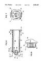
- FIG. 6is a longitudinal sectional view of the inner tube of a blood collection tube holder embodiment of the invention.
- FIG. 7is an end view of the inner tube of FIG. 6, taken along line 7--7 of FIG. 6;
- FIG. 8is a side view of the inner tube ratchet means shown in FIG. 6;
- FIG. 9ais plan view of the inner tube for the prefilled syringe embodiment of the safety-needled invention.
- FIG. 9bis a plan view of the plunger arm for a prefilled syringe.
- FIGS. 1-4show the basic structure of the improved safety-needled device of the invention, with FIG. 5a showing the syringe embodiment with the needle exposed and ready for use, and FIG. 5b showing the syringe embodiment after use with the outer shield in its forwardmost position in which the needle is covered, FIGS. 6-8 showing the blood collection tube holder of the invention, and FIG. 9 showing the prefilled syringe embodiment of the invention.
- the improved safety medical devicecomprises two generally cylindrical pieces, a hollow inner tube 10 and an outer shield 12, both pieces typically being made of molded plastic or other acceptable material. Molded into the forward end of the outer surface of inner tube 10 is a rachet assembly 14 including locking teeth which are shown in detail in FIGS. 7 and 8 with reference to the blood collection tube holder embodiment.
- Inner tube 10is also adapted to securely mate typically with a threaded structure to hold a standard hollow needle 16 shown with a removable needle cover 18 thereon
- Inner tube 10is further provided with a cavity 22 into which drugs, pharmaceuticals, blood or other fluids may be aspirated and then forced through needle 16 into a body, or into which a blood collection tube may be placed so that blood from the body may be drawn.
- a flange 24is molded at the rearward end of inner tube 10 to act as a finger support while forcing the contents in the cavity into the body, or while withdrawing the needle from the patient, pharmaceutical vial, or other container.
- Circumferential grooves 36 and 38are formed in wall 42.
- An end wall 44extends from the forwardmost end of wall 42 and supports ratchet assembly 14 which is integral therewith and is described in more detail hereinafter with respect to the blood collection tube holder embodiment shown in FIGS. 6-8.
- a shoulder 46is formed, the rearward extension of shoulder 46 forming the forwardmost ledge 48 of circumferential groove 38.
- the rearmost ledge 50 of groove 38has a slightly smaller diameter than that of shoulder 46, and as wall 42 extends rearward from ledge 50, its outside diameter gradually decreases to form a sloped wall portion or ramp generally illustrated by 52.
- the wall 42is of constant diameter until it reaches slightly raised shoulder 54 which forms the forwardmost ledge 56 of circumferential groove 36.
- the forwardmost portion of flange 24forms the rearwardmost ledge of groove 36, and flange 24 has tine 57 for added finger support.
- the outer shield 12has an inside diameter which is slightly larger than the outer diameter of the inner tube 10.
- the outer shield 12is adapted to fit over inner tube 10 and to be slidable between a rearward position and a forward position (as respectively shown in FIGS. 5a and 5b for the syringe embodiment).
- the outer shield 12has a locking nozzle or ratchet means 26 molded into its inner surface at the forward end thereof, the locking nozzle including a plurality of locking notches, shown particularly in FIGS. 2 and 3.
- Locking nozzle 26is preferably annular in shape and is connected to the outer cylindrical wall 70 of shield 12 by end wall 72.
- a substantially annular opening 74 at the center of locking nozzle 26is adapted to permit a standard needle 16 to extend therethrough when the shield 12 is in its closed position.
- the locking nozzle 26engages the locking teeth in the rachet assembly 14 when the shield 12 is in its rearward (retracted) position, thereby preventing rotation of the outer shield 12 relative to the inner tube 10 during an injection or phlebotomy.
- a flanged safety ridge 28is formed near the forward end of outer shield 12 to assist the user in grasping the shield 12 and slidably moving it from its retracted position to its extended and locked position.
- the shield 12also has at its rearmost end a plurality of circumferentially spaced axial slots 30 which form there-between tabs 32, the tabs 32 being slightly flexible.
- Formed on the inner surface of tabs 32are a plurality of protrusions or lug members 34 (seen in FIG. 4) which are adapted to yieldingly engage a circumferential groove 36 preferably located at the rear end of inner tube 10 to thereby maintain the shield 12 in its retracted position (shown in FIG. 5a with respect to the syringe embodiment).
- the tabs 32are sufficiently flexible to permit the lug members 34 to be forced out of groove 36, and to permit the shield 12 to be moved forward manually to its extended or locked position (shown in FIG. 5b with respect to the syringe embodiment) in which the lug members 34 engage a second circumferential groove 38.
- the construction of the shield 12 and inner tube 10are such that the shield 12, when in the extended locked position with lug members 34 locked into groove 38, is extremely difficult to remove from the inner tube 10, while during assembly, the shield 12 is slipped over tube 10 without lug members 34 locking into groove 38.
- a plurality of notches or grooves 76are formed on the inside wall of locking nozzle 26.
- the notches 76are designed and sized to mesh with the raised teeth 66 (seen in FIG. 7) extending from the outside of wall 60 of ratchet assembly 14 when shield 12 is positioned as shown in FIG. 5a with respect to the syringe embodiment.
- the meshing of the teeth 66 and notches 76prevents rotation of shield 12 relative to inner tube 10 which could be distracting to the medical personnel using the medical device.
- twenty-four notches 76are shown extending completely about the inside wall of locking nozzle 26, the exact number and shape may be varied and will be dependent on the size, shape and location of raised teeth 66. With raised teeth 66 on opposite sides of wall 60, the teeth 66 will mesh with notches 76 regardless of the relative circumferential alignment between inner tube 10 an outer shield 12.
- tab 32 and their corresponding lug members 34provide advantages in assembling the shielded medical device, and in moving the shield 12 from its unshielded (open) to its shielded (closed) position.
- the precise size and shape of lug members 34may be changed to suit the particular situation.
- FIGS. 5a and 5bthe safety-needled syringe embodiment of the invention is shown, with like numbers indicating like parts.
- the outer shield 12is in its retracted position relative to the inner syringe tube 10 such that needle 16 is unshielded Ratchet means 14 of the syringe tube 10, and locking nozzle 26 of the outer shield 12 are engaged to prevent rotation of the shield relative to the inner syringe tube 10, while lug member 34 of tabs 32 are seated in 3 circumferential groove 36.
- FIGS. 5athe outer shield 12 is in its retracted position relative to the inner syringe tube 10 such that needle 16 is unshielded Ratchet means 14 of the syringe tube 10, and locking nozzle 26 of the outer shield 12 are engaged to prevent rotation of the shield relative to the inner syringe tube 10, while lug member 34 of tabs 32 are seated in 3 circumferential groove 36.
- inner syringe tube 10as arranged to be generally cylindrical in shape, and at its forward end is shaped to accommodate the typically rubber end of a standard plunger 20.
- chamber 22 of the syringe tube 10is shown accepting plunger 20 which will either force the contents of chamber 22 through a small annular opening 58a in the ratchet assembly 14 and into and through the needle 16, or aspirate a fluid through the needle 16, the small annular opening 58a in the ratchet assembly, and into the chamber 22.
- graduated markings 40typically in cc measurements are placed on shield 12 for clear visibility, although since shield 12 is preferably transparent, the markings 40 may be placed on the syringe tube 10.
- the shield 12is essentially identical for all of the medical devices of the invention, its exact length and shape at the front end is dependent on the device with which it is to engage so as to prevent rotation.
- rachet assembly 14has an annular opening 58b at the center thereof.
- the ratchet 14 assembly of inner tube 10 of the blood collection tube holderhas a cylindrical forwardly extending wall 60 which is provided at the inside circumference thereof with threads 62 or other means by which a standard hollow needle may be attached and communicate through annular opening 58b with cavity 22.
- inner tube 10is also provided with a rearwardly extending cylindrical wall 64 may be shaped to receive the forward end of a vacuum blood collection vial (not shown) in sealing engagement therebetween.
- the flange 28 on the outer shield 12not only provides a safety ridge for grasping and pushing shield 12, but may be used as a vacuum vial penetration indicator line.
- the self-sealing rubber end of the vacuum vialmay be axially inserted up until that point without the back point of the standard phlebotomy needle puncturing the same.
- the rachet assembly 14 of the inner tube 10includes a plurality of raised teeth 66, which as seen in FIGS. 7 and 8 extend outwardly from the outside surface of wall 60 of rachet assembly 14.
- Five teeth 66are shown on diametrically opposed sides of wall 60, but the exact number and exact location of the teeth 66 may be varied.
- the teeth 66mesh with notches 76 of in the locking nozzle 26 of shield 12 to prevent rotation of shield 12 relative to inner tube 10 when the shield is in its retracted position.
- the inner tube 110 of the prefilled safety syringe embodiment of the inventionis seen in FIG. 9a, with the disposable plunger arm 105 seen in FIG. 9b. (In this embodiment corresponding elements will have corresponding numbers with the numbers of FIG. 9a being greater by one hundred).
- the inner tube 110 of FIG. 9acombines many of the standard features of a prefilled syringe with the afore-described inner tube features of the instant safety-needled invention
- the inner tube 110is preferably made of or lined with glass.
- the medicated liquid 121is maintained in chamber 122 which is bounded by the cylindrical wall 142, a shaped metal cap 145 having an hermetic seal 147, and a rubber plunger seal 149 having a male threaded member 151 extending therefrom.
- the rear end of the inner tube 110is provided with a groove 161 for a preferably plastic snap-on flange 163, while the front end metal cap 145 is arranged to mate with a needle hub 165 having a ridge ring 167 on one end for mating with the metal cap 145 , and means for accepting and holding a double pointed needle 116 on the other end.
- the needle 116is provided with a protective cover 118 which must be removed before an injection.
- a disposable plunger arm 105 seen in FIG. 9bis provided with a female thread member 181 which is screwed onto the male threaded member 151 of the inner tube 110 prior to injection. After mating, force may be applied to the plunger arm 105 so as to force the medicated liquid out through the double pointed needle 116.
- the inner tube 110also includes the safety-needled features.
- front and rear grooves 138 and 136into which the lugs of an outer shield may extend, with front groove 138 being deeper than rear groove 136.
- the outer surface of inner tube 110is provided with a shoulder 146 which prevents the outer shield from leaving the front groove 138, as well as a ramped surface 152 which helps provide the clicking/locking action.
- the open end of the outer shield 12is forced over the shoulder 46 (146) of the inner tube 10 (110), (FIG. 9 numbers not being listed hereafter).
- the lug members 34 attached to tabs 32initially contact the sloped wall portion 90 (FIG. 1) and the sloped wall portion 90 forces the flexible tabs 32 outwardly in a fanlike manner.
- the lug members 34pass over and by raised shoulder 46, they instantaneously remain spread, both due to the contraction time required to reassume an unstressed position and due to the position assumed with the tabs angling away from wall 42 of tube 10, such that they can be quickly moved past groove 38 without falling into groove 38.
- the lug members 34press against ramp 52 which is of decreasing diameter, i.e. the tabs 32 are no longer flexed outwardly as a result of the reduced diameter of wall 42, and become parallel.
- the lug members 34 at the end of the shield 12ultimately pass over slightly raised shoulder 54, and lug members 34 fall into circumferential groove 36, where the shield 12 is substantially fixed as shown in FIG. 5a.
- circumferential groove 36is not as deep as circumferential groove 38, lug members 34 are not deeply seated in circumferential groove 36. Since tabs 32 are slightly flexible, it does not take a great deal of force to push the lugs 34 out of groove 36 and over raised shoulder 54. As the shield 12 is pushed forward, the lug members 34 contact ramp 52 in a direction in which the diameter of the wall 42 is increasing. This provides increased friction and tension on the tabs 32, i.e., the user is aware of the increase in force needed to keep the shield 12 moving forward.
- the lug members 34eventually fall into circumferential groove 38 with an audible click, providing a positive indication of locking beyond the visual indication. Because of its depth and because of the increased diameter of raised shoulder 46, groove 38 retains the shield fixed as shown in FIG. 5b. It is difficult to remove the shield once it is locked into circumferential groove 38, and a positive lock is assured, completely protecting medical personnel and others against needlestick injuries from the contaminated needle 16. The shielded medical device is then safely discarded in accord with established procedures.
- the shielded safety medical devices of this inventionmay be used in numerous circumstances and for differing purposes, all of which are within the scope of this invention
- a common usewould be by a phlebotomist (clinician) for obtaining blood samples from a patient.
- the phlebotomist (clinician)screws a capped sterile blood collection needle 16 into the threads 62 of inner tube 10.
- the phlebotomy needle(not shown) extends a short distance into cavity 22 of the inner tube 10, and a vacuum vial (not shown) having a rubber or plastic stopper is inserted into the tube 10 rather than a plunger.
- the stopper of the vacuum vialis penetrated by contact with the rearward extension of the needle, and blood is drawn into the vacuum vial through the needle which has been inserted into a vein of the patient.
- the needleis removed from the patient, the vacuum vial(s) now filled with a blood sample(s) is removed from the inner tube 10, and the phlebotomist (clinician) then slides the shield 12 over the inner tube 10 until the shield clicks and locks in place, thereby protecting personnel from injury from the contaminated needle or blood.
- the shielded blood collection tube holderis then safely disposed of, protecting against potential injuries an inadvertent contamination.
- the clinicianattaches the appropriate size needle to the syringe tube, removes the end cap and aspirates the required drug, medication, or blood into the syringe.
- the drug, medication, or other liquidis then administered to the patient directly by injection or through I.V. administration lines.
- the safety shieldis moved forward until the lugs of the tabs of the outer shield click and lock securely in the forward groove in the syringe tube. With such a procedure, the shield surrounds the needle as shown in FIG. 5b, and the syringe and contaminated needle may then be safely discarded.
- the locations of the grooves in the inner tube of the embodimentswere described as being at the forward and rear ends of the inner tube, those skilled in the art will appreciate that the exact location is not critical provided the contaminated needle is shielded by the shield after use. Thus, if the needle is short relative to the shield, the front groove can be located further back on the inner tube. Without jeopardizing the effectiveness of the device. Likewise, if the inner tube is long relative to the shield, the rear groove can be located away from the rear of the inner tube without the shield interfering with the needle when the shield is in its retracted position. Further yet, while the rear portion of the outer shield was described as having axial "slits", the slits may be thought of as "slots".
Landscapes
- Health & Medical Sciences (AREA)
- Engineering & Computer Science (AREA)
- Heart & Thoracic Surgery (AREA)
- Vascular Medicine (AREA)
- Anesthesiology (AREA)
- Biomedical Technology (AREA)
- Environmental & Geological Engineering (AREA)
- Hematology (AREA)
- Life Sciences & Earth Sciences (AREA)
- Animal Behavior & Ethology (AREA)
- General Health & Medical Sciences (AREA)
- Public Health (AREA)
- Veterinary Medicine (AREA)
- Infusion, Injection, And Reservoir Apparatuses (AREA)
Abstract
Description
Claims (19)
Priority Applications (14)
| Application Number | Priority Date | Filing Date | Title |
|---|---|---|---|
| US07/162,569US5059185A (en) | 1988-03-01 | 1988-03-01 | Safety needled medical devices |
| US07/224,920US4923445A (en) | 1988-03-01 | 1988-07-27 | Safety needled medical devices |
| US07/257,407US5088982A (en) | 1988-03-01 | 1988-10-13 | Safety winged needle medical devices |
| US07/303,588US5067945A (en) | 1988-03-01 | 1989-01-27 | Safety needled medical devices capable of one-handed manipulation |
| AU30716/89AAU3071689A (en) | 1988-03-01 | 1989-02-24 | Safety needled medical devices capable of one-handed manipulation |
| DE89302013TDE68908584T2 (en) | 1988-03-01 | 1989-02-28 | Protected needle medical device. |
| ES198989302013TES2046464T3 (en) | 1988-03-01 | 1989-02-28 | MEDICAL DEVICES WITH SAFETY NEEDLE. |
| KR1019890002380AKR910008024B1 (en) | 1988-03-01 | 1989-02-28 | One-handed adjustable needle medical device |
| EP89302013AEP0331452B1 (en) | 1988-03-01 | 1989-02-28 | Safety needled medical devices |
| CN89101033ACN1013343B (en) | 1988-03-01 | 1989-02-28 | Safety needled medical devices capable of one handed manipulation |
| CA000592266ACA1324546C (en) | 1988-03-01 | 1989-02-28 | Safety needles medical devices capable of one handed manipulation |
| JP1049737AJP2791082B2 (en) | 1988-03-01 | 1989-03-01 | Medical instrument with needle |
| US07/416,927US5085639A (en) | 1988-03-01 | 1989-10-04 | Safety winged needle medical devices |
| US07/551,142US5154699A (en) | 1988-03-01 | 1990-07-11 | Safety winged needle device for use with fistulas |
Applications Claiming Priority (1)
| Application Number | Priority Date | Filing Date | Title |
|---|---|---|---|
| US07/162,569US5059185A (en) | 1988-03-01 | 1988-03-01 | Safety needled medical devices |
Related Child Applications (5)
| Application Number | Title | Priority Date | Filing Date |
|---|---|---|---|
| US07/224,920Continuation-In-PartUS4923445A (en) | 1988-03-01 | 1988-07-27 | Safety needled medical devices |
| US07/257,407Continuation-In-PartUS5088982A (en) | 1988-03-01 | 1988-10-13 | Safety winged needle medical devices |
| US07/303,588Continuation-In-PartUS5067945A (en) | 1988-03-01 | 1989-01-27 | Safety needled medical devices capable of one-handed manipulation |
| US07/416,927Continuation-In-PartUS5085639A (en) | 1988-03-01 | 1989-10-04 | Safety winged needle medical devices |
| US07/551,142Continuation-In-PartUS5154699A (en) | 1988-03-01 | 1990-07-11 | Safety winged needle device for use with fistulas |
Publications (1)
| Publication Number | Publication Date |
|---|---|
| US5059185Atrue US5059185A (en) | 1991-10-22 |
Family
ID=22586193
Family Applications (1)
| Application Number | Title | Priority Date | Filing Date |
|---|---|---|---|
| US07/162,569Expired - Fee RelatedUS5059185A (en) | 1988-03-01 | 1988-03-01 | Safety needled medical devices |
Country Status (1)
| Country | Link |
|---|---|
| US (1) | US5059185A (en) |
Cited By (44)
| Publication number | Priority date | Publication date | Assignee | Title |
|---|---|---|---|---|
| US5147326A (en)* | 1988-06-28 | 1992-09-15 | Sherwood Medical Company | Combined syringe and needle shield and method of manufacture |
| US5160326A (en)* | 1988-06-28 | 1992-11-03 | Sherwood Medical Company | Combined syringe and needle shield |
| US5217437A (en)* | 1988-06-28 | 1993-06-08 | Sherwood Medical Company | Needle protecting device |
| US5226894A (en)* | 1990-09-11 | 1993-07-13 | Sterling Winthrop Inc. | Safety syringe assembly with radially deformable body |
| US5290255A (en)* | 1993-02-02 | 1994-03-01 | Vallelunga Anthony J | Apparatus for shielding a syringe needle |
| US5306258A (en)* | 1991-04-03 | 1994-04-26 | Fuente Ricardo L De | Safety syringe and method of using same |
| US5342309A (en)* | 1993-03-05 | 1994-08-30 | Becton, Dickinson And Company | Syringe having safety shield |
| US5344407A (en)* | 1993-05-04 | 1994-09-06 | Ryan Dana W | Safety holder for pre-filled disposable syringe cartridge |
| US5385555A (en)* | 1993-01-08 | 1995-01-31 | Becton, Dickinson And Company | Lockable safety shield for hypodermic syringe |
| US5498243A (en)* | 1995-01-31 | 1996-03-12 | Unique Management Enterprises, Inc. | Apparatus for shielding a syringe needle |
| US5624400A (en)* | 1990-05-09 | 1997-04-29 | Safety Syringes, Inc. | Disposable self-shielding aspirating syringe |
| US5733264A (en)* | 1997-01-22 | 1998-03-31 | Becton, Dickinson And Company | Shieldable syringe assembly |
| US5746727A (en)* | 1994-10-21 | 1998-05-05 | Becton, Dickinson And Company | Safety needle assembly having telescoping shield |
| US5843047A (en)* | 1997-01-29 | 1998-12-01 | Okanogan House, Inc. | Syringe with integral safety cover |
| US6004296A (en)* | 1997-09-30 | 1999-12-21 | Becton Dickinson France, S.A. | Lockable safety shield assembly for a prefillable syringe |
| WO2000020070A1 (en)* | 1998-10-05 | 2000-04-13 | Rymed Technologies, Inc. | Swabbable needleless low reflux injection port system |
| US6059756A (en)* | 1998-11-04 | 2000-05-09 | Yeh; Song-Hwa | Safety injection device |
| US6171283B1 (en)* | 1997-03-10 | 2001-01-09 | Safety Syringes, Inc. | Disposable self-shielding unit dose syringe guard |
| US6319233B1 (en) | 1998-04-17 | 2001-11-20 | Becton, Dickinson And Company | Safety shield system for prefilled syringes |
| US20020077522A1 (en)* | 2000-12-15 | 2002-06-20 | Kawasumi Laboratories, Inc. | Protective tool for therapeutic material delivery device, cartridge for therapeutic material delivery device, and a therapeutic material delivery device |
| US6679864B2 (en) | 1998-04-17 | 2004-01-20 | Becton Dickinson And Company | Safety shield system for prefilled syringes |
| US6719730B2 (en) | 1998-04-17 | 2004-04-13 | Becton, Dickinson And Company | Safety shield system for prefilled syringes |
| US20050033242A1 (en)* | 1997-03-10 | 2005-02-10 | Safety Syringes, Inc. | Disposable self-shielding unit dose syringe guard |
| US20050043688A1 (en)* | 2003-08-19 | 2005-02-24 | Gremel Robert F. | Apparatus for retaining concentric parts within one another |
| US20050148944A1 (en)* | 2003-12-24 | 2005-07-07 | Hsin-Po Hsieh | Syringe safety sleeve |
| US20060100589A1 (en)* | 2004-08-10 | 2006-05-11 | Biotop Technology Co. Ltd. | Syringe safety sleeve |
| US20060195062A1 (en)* | 2005-02-25 | 2006-08-31 | Gremel Robert F | Apparatus for locking concentric components in alignment |
| US7118552B2 (en) | 2000-02-18 | 2006-10-10 | Astrazeneca Ab | Automatically operable safety shield system for syringes |
| US20070113861A1 (en)* | 2005-11-08 | 2007-05-24 | Novo Nordisk A/S | Cap for a medical device |
| US20080125673A1 (en)* | 2006-09-08 | 2008-05-29 | Becton, Dickinson And Company | Sample container with physical fill-line indicator |
| US20080132845A1 (en)* | 2000-02-10 | 2008-06-05 | Shigeru Nemoto | Syringe Barrel With Reinforcing Rib |
| US20080144739A1 (en)* | 1998-09-17 | 2008-06-19 | At&T Mobility Ii Llc | Maximum ratio transmission |
| US20080228147A1 (en)* | 2007-03-15 | 2008-09-18 | Bristol-Myers Squibb Company | Injector for use with pre-filled syringes and method of assembly |
| US7985216B2 (en) | 2004-03-16 | 2011-07-26 | Dali Medical Devices Ltd. | Medicinal container engagement and automatic needle device |
| US20110202011A1 (en)* | 2008-08-28 | 2011-08-18 | Owen Mumford Limited | Autoinjection devices |
| US20120095408A1 (en)* | 2009-05-01 | 2012-04-19 | Owen Mumford Limited | Injection devices |
| US20120316466A1 (en)* | 2011-06-08 | 2012-12-13 | Becton, Dickinson And Company | Safety Syringe Having A Manually Activated Retractable Needle |
| US8372044B2 (en) | 2005-05-20 | 2013-02-12 | Safety Syringes, Inc. | Syringe with needle guard injection device |
| US8376998B2 (en) | 2003-09-17 | 2013-02-19 | Elcam Medical Agricultural Cooperative Association Ltd. | Automatic injection device |
| US20140135706A1 (en)* | 2008-06-02 | 2014-05-15 | Sta-Med, Llc | Needle cover |
| US20160067410A1 (en)* | 2013-05-17 | 2016-03-10 | Carrtech Llc | Filtering Needle Cap |
| US9694140B2 (en) | 2010-06-23 | 2017-07-04 | Sta-Med, Llc | Automatic-locking safety needle covers and methods of use and manufacture |
| US9848810B2 (en) | 2011-05-31 | 2017-12-26 | Sta-Med, Llc | Blood collection safety devices and methods of use and manufacture |
| US11857768B1 (en) | 2022-10-01 | 2024-01-02 | CARRTECH Corp. | Filtering needle assembly with seal plug |
Citations (21)
| Publication number | Priority date | Publication date | Assignee | Title |
|---|---|---|---|---|
| US2571653A (en)* | 1950-02-25 | 1951-10-16 | Bastien Victor Gerard | Syringe |
| US3073306A (en)* | 1958-09-03 | 1963-01-15 | Linder Fritz | Hypodermic syringe |
| US3469581A (en)* | 1967-10-23 | 1969-09-30 | Burron Medical Prod Inc | Syringe and needle adapter assembly |
| US4356822A (en)* | 1980-10-17 | 1982-11-02 | Winstead Hall Deborah | Syringe assembly |
| US4417887A (en)* | 1981-10-30 | 1983-11-29 | Fuji Terumo Co., Ltd. | Connector for catheter |
| US4425120A (en)* | 1982-04-15 | 1984-01-10 | Sampson Norma A | Shielded hypodermic syringe |
| US4573976A (en)* | 1984-05-24 | 1986-03-04 | Dolores A. Smith | Shielded needle |
| US4631057A (en)* | 1985-12-17 | 1986-12-23 | Dolores A. Smith | Shielded needle |
| US4643199A (en)* | 1986-02-28 | 1987-02-17 | Jennings Jr Baldwin P | Safety blood sample apparatus |
| US4655751A (en)* | 1986-02-14 | 1987-04-07 | Harbaugh John T | Liquid dispensing and receiving syringe |
| US4666435A (en)* | 1986-05-22 | 1987-05-19 | Braginetz Paul A | Shielded medical syringe |
| US4681567A (en)* | 1986-04-03 | 1987-07-21 | Masters Edwin J | Syringe with safety sheath |
| US4702739A (en)* | 1985-11-27 | 1987-10-27 | Milorad Milosevic M | Holder for a syringe to facilitate injection procedure |
| US4702738A (en)* | 1986-05-22 | 1987-10-27 | Spencer Treesa A | Disposable hypodermic syringe and needle combination having retractable, accident preventing sheath |
| US4723943A (en)* | 1986-12-31 | 1988-02-09 | Montana Deaconess Medical Center | Sheathed syringe |
| US4737144A (en)* | 1987-03-09 | 1988-04-12 | Choksi Pradip V | Syringe with selectively exposed and enveloped needle |
| US4738603A (en)* | 1983-03-08 | 1988-04-19 | Kabushiki Kaisha Toyota Chuo Kenkyusho | Hydraulic vane pump |
| US4747837A (en)* | 1987-05-01 | 1988-05-31 | Hauck Martin W | Syringe needle recapping protective device |
| US4747830A (en)* | 1986-04-28 | 1988-05-31 | Gloyer Walter W | Anti-stick contagion free disposable hypodermic safety syringe |
| US4788231A (en)* | 1987-07-14 | 1988-11-29 | Huls Aktiengesellschaft | Process for producing pourable powdered rubber containing filler |
| US4790827A (en)* | 1987-04-27 | 1988-12-13 | Habley Medical Technology Corporation | Shielded safety syringe |
- 1988
- 1988-03-01USUS07/162,569patent/US5059185A/ennot_activeExpired - Fee Related
Patent Citations (21)
| Publication number | Priority date | Publication date | Assignee | Title |
|---|---|---|---|---|
| US2571653A (en)* | 1950-02-25 | 1951-10-16 | Bastien Victor Gerard | Syringe |
| US3073306A (en)* | 1958-09-03 | 1963-01-15 | Linder Fritz | Hypodermic syringe |
| US3469581A (en)* | 1967-10-23 | 1969-09-30 | Burron Medical Prod Inc | Syringe and needle adapter assembly |
| US4356822A (en)* | 1980-10-17 | 1982-11-02 | Winstead Hall Deborah | Syringe assembly |
| US4417887A (en)* | 1981-10-30 | 1983-11-29 | Fuji Terumo Co., Ltd. | Connector for catheter |
| US4425120A (en)* | 1982-04-15 | 1984-01-10 | Sampson Norma A | Shielded hypodermic syringe |
| US4738603A (en)* | 1983-03-08 | 1988-04-19 | Kabushiki Kaisha Toyota Chuo Kenkyusho | Hydraulic vane pump |
| US4573976A (en)* | 1984-05-24 | 1986-03-04 | Dolores A. Smith | Shielded needle |
| US4702739A (en)* | 1985-11-27 | 1987-10-27 | Milorad Milosevic M | Holder for a syringe to facilitate injection procedure |
| US4631057A (en)* | 1985-12-17 | 1986-12-23 | Dolores A. Smith | Shielded needle |
| US4655751A (en)* | 1986-02-14 | 1987-04-07 | Harbaugh John T | Liquid dispensing and receiving syringe |
| US4643199A (en)* | 1986-02-28 | 1987-02-17 | Jennings Jr Baldwin P | Safety blood sample apparatus |
| US4681567A (en)* | 1986-04-03 | 1987-07-21 | Masters Edwin J | Syringe with safety sheath |
| US4747830A (en)* | 1986-04-28 | 1988-05-31 | Gloyer Walter W | Anti-stick contagion free disposable hypodermic safety syringe |
| US4666435A (en)* | 1986-05-22 | 1987-05-19 | Braginetz Paul A | Shielded medical syringe |
| US4702738A (en)* | 1986-05-22 | 1987-10-27 | Spencer Treesa A | Disposable hypodermic syringe and needle combination having retractable, accident preventing sheath |
| US4723943A (en)* | 1986-12-31 | 1988-02-09 | Montana Deaconess Medical Center | Sheathed syringe |
| US4737144A (en)* | 1987-03-09 | 1988-04-12 | Choksi Pradip V | Syringe with selectively exposed and enveloped needle |
| US4790827A (en)* | 1987-04-27 | 1988-12-13 | Habley Medical Technology Corporation | Shielded safety syringe |
| US4747837A (en)* | 1987-05-01 | 1988-05-31 | Hauck Martin W | Syringe needle recapping protective device |
| US4788231A (en)* | 1987-07-14 | 1988-11-29 | Huls Aktiengesellschaft | Process for producing pourable powdered rubber containing filler |
Cited By (75)
| Publication number | Priority date | Publication date | Assignee | Title |
|---|---|---|---|---|
| US5160326A (en)* | 1988-06-28 | 1992-11-03 | Sherwood Medical Company | Combined syringe and needle shield |
| US5217437A (en)* | 1988-06-28 | 1993-06-08 | Sherwood Medical Company | Needle protecting device |
| US5147326A (en)* | 1988-06-28 | 1992-09-15 | Sherwood Medical Company | Combined syringe and needle shield and method of manufacture |
| USRE37439E1 (en)* | 1990-05-09 | 2001-11-06 | Safety Syringes, Inc. | Disposable self-shielding aspirating syringe |
| US5624400A (en)* | 1990-05-09 | 1997-04-29 | Safety Syringes, Inc. | Disposable self-shielding aspirating syringe |
| US5226894A (en)* | 1990-09-11 | 1993-07-13 | Sterling Winthrop Inc. | Safety syringe assembly with radially deformable body |
| US5531706A (en)* | 1991-04-03 | 1996-07-02 | Protecs Syringes International Corporation | Safety syringe |
| US5306258A (en)* | 1991-04-03 | 1994-04-26 | Fuente Ricardo L De | Safety syringe and method of using same |
| US5385555A (en)* | 1993-01-08 | 1995-01-31 | Becton, Dickinson And Company | Lockable safety shield for hypodermic syringe |
| US5290255A (en)* | 1993-02-02 | 1994-03-01 | Vallelunga Anthony J | Apparatus for shielding a syringe needle |
| US5342309A (en)* | 1993-03-05 | 1994-08-30 | Becton, Dickinson And Company | Syringe having safety shield |
| US5344407A (en)* | 1993-05-04 | 1994-09-06 | Ryan Dana W | Safety holder for pre-filled disposable syringe cartridge |
| US5746727A (en)* | 1994-10-21 | 1998-05-05 | Becton, Dickinson And Company | Safety needle assembly having telescoping shield |
| US5498243A (en)* | 1995-01-31 | 1996-03-12 | Unique Management Enterprises, Inc. | Apparatus for shielding a syringe needle |
| US5733264A (en)* | 1997-01-22 | 1998-03-31 | Becton, Dickinson And Company | Shieldable syringe assembly |
| US5843047A (en)* | 1997-01-29 | 1998-12-01 | Okanogan House, Inc. | Syringe with integral safety cover |
| US6171283B1 (en)* | 1997-03-10 | 2001-01-09 | Safety Syringes, Inc. | Disposable self-shielding unit dose syringe guard |
| US7041085B2 (en) | 1997-03-10 | 2006-05-09 | Safety Syrines, Inc. | Disposable self-shielding unit dose syringe guard |
| US20050054987A1 (en)* | 1997-03-10 | 2005-03-10 | Safety Syringes, Inc. | Disposable self-shielding unit dose syringe guard |
| US20050033242A1 (en)* | 1997-03-10 | 2005-02-10 | Safety Syringes, Inc. | Disposable self-shielding unit dose syringe guard |
| US6638256B2 (en) | 1997-09-30 | 2003-10-28 | Becton Dickinson France S.A. | Lockable safety shield assembly for a prefillable syringe |
| US6193696B1 (en) | 1997-09-30 | 2001-02-27 | Becton Dickinson France, S.A. | Lockable safety shield assembly for a prefillable syringe |
| US6004296A (en)* | 1997-09-30 | 1999-12-21 | Becton Dickinson France, S.A. | Lockable safety shield assembly for a prefillable syringe |
| US6319233B1 (en) | 1998-04-17 | 2001-11-20 | Becton, Dickinson And Company | Safety shield system for prefilled syringes |
| US6626864B2 (en) | 1998-04-17 | 2003-09-30 | Becton Dickinson France, S.A. | Safety shield system for prefilled syringes |
| US6679864B2 (en) | 1998-04-17 | 2004-01-20 | Becton Dickinson And Company | Safety shield system for prefilled syringes |
| US6685676B2 (en) | 1998-04-17 | 2004-02-03 | Becton Dickinson And Company | Safety shield system for prefilled syringes |
| US6719730B2 (en) | 1998-04-17 | 2004-04-13 | Becton, Dickinson And Company | Safety shield system for prefilled syringes |
| US20080144739A1 (en)* | 1998-09-17 | 2008-06-19 | At&T Mobility Ii Llc | Maximum ratio transmission |
| AU765829B2 (en)* | 1998-10-05 | 2003-10-02 | Rymed Technologies, Llc | Swabbable needleless low reflux injection port system |
| WO2000020070A1 (en)* | 1998-10-05 | 2000-04-13 | Rymed Technologies, Inc. | Swabbable needleless low reflux injection port system |
| US6059756A (en)* | 1998-11-04 | 2000-05-09 | Yeh; Song-Hwa | Safety injection device |
| US7794435B2 (en)* | 2000-02-10 | 2010-09-14 | Shigeru Nemoto | Syringe barrel with reinforcing rib |
| US20080132845A1 (en)* | 2000-02-10 | 2008-06-05 | Shigeru Nemoto | Syringe Barrel With Reinforcing Rib |
| US7500964B2 (en) | 2000-02-18 | 2009-03-10 | Astrazeneca Ab | Automatically operable safety shield system for syringes |
| US7118552B2 (en) | 2000-02-18 | 2006-10-10 | Astrazeneca Ab | Automatically operable safety shield system for syringes |
| US6988981B2 (en) | 2000-12-15 | 2006-01-24 | Kawasumi Laboratories, Inc. | Protective tool for therapeutic material delivery device, cartridge for therapeutic material delivery device, and a therapeutic material delivery device |
| US20040122351A1 (en)* | 2000-12-15 | 2004-06-24 | Kawasumi Laboratories, Inc. | Protective tool for therapeutic material delivery device, cartridge for therapeutic material delivery device, and a therapeutic material delivery device |
| US20020077522A1 (en)* | 2000-12-15 | 2002-06-20 | Kawasumi Laboratories, Inc. | Protective tool for therapeutic material delivery device, cartridge for therapeutic material delivery device, and a therapeutic material delivery device |
| US6723037B2 (en)* | 2000-12-15 | 2004-04-20 | Kawasumi Laboratories, Inc. | Protective tool for therapeutic material delivery device, cartridge for therapeutic material delivery device, and a therapeutic material delivery device |
| US20050043688A1 (en)* | 2003-08-19 | 2005-02-24 | Gremel Robert F. | Apparatus for retaining concentric parts within one another |
| US6994694B2 (en) | 2003-08-19 | 2006-02-07 | Saftey 1St Medical, Inc. | Apparatus for retaining concentric parts within one another |
| EP2650033A2 (en) | 2003-09-17 | 2013-10-16 | Elcam Medical Agricultural Cooperative Association Ltd. | Automatic injection device |
| US8376998B2 (en) | 2003-09-17 | 2013-02-19 | Elcam Medical Agricultural Cooperative Association Ltd. | Automatic injection device |
| US11623051B2 (en) | 2003-09-17 | 2023-04-11 | E3D Agricultural Cooperative Association Ltd. | Automatic injection device |
| US20050148944A1 (en)* | 2003-12-24 | 2005-07-07 | Hsin-Po Hsieh | Syringe safety sleeve |
| US7985216B2 (en) | 2004-03-16 | 2011-07-26 | Dali Medical Devices Ltd. | Medicinal container engagement and automatic needle device |
| US20060100589A1 (en)* | 2004-08-10 | 2006-05-11 | Biotop Technology Co. Ltd. | Syringe safety sleeve |
| US20060195062A1 (en)* | 2005-02-25 | 2006-08-31 | Gremel Robert F | Apparatus for locking concentric components in alignment |
| US8372044B2 (en) | 2005-05-20 | 2013-02-12 | Safety Syringes, Inc. | Syringe with needle guard injection device |
| US20070113861A1 (en)* | 2005-11-08 | 2007-05-24 | Novo Nordisk A/S | Cap for a medical device |
| US9409176B2 (en) | 2006-09-08 | 2016-08-09 | Becton, Dickinson And Company | Sample container with physical fill-line indicator |
| US20080125673A1 (en)* | 2006-09-08 | 2008-05-29 | Becton, Dickinson And Company | Sample container with physical fill-line indicator |
| US20080228147A1 (en)* | 2007-03-15 | 2008-09-18 | Bristol-Myers Squibb Company | Injector for use with pre-filled syringes and method of assembly |
| US20140135706A1 (en)* | 2008-06-02 | 2014-05-15 | Sta-Med, Llc | Needle cover |
| US10335554B2 (en)* | 2008-06-02 | 2019-07-02 | Sta-Med, Llc | Needle cover |
| US11090443B2 (en) | 2008-06-02 | 2021-08-17 | Sta-Med, Llc | Needle cover |
| US11992665B2 (en) | 2008-06-02 | 2024-05-28 | Sta-Med, Llc | Needle cover |
| US9242053B2 (en)* | 2008-08-28 | 2016-01-26 | Owen Mumford Limited | Autoinjection devices |
| US20110202011A1 (en)* | 2008-08-28 | 2011-08-18 | Owen Mumford Limited | Autoinjection devices |
| US20120095408A1 (en)* | 2009-05-01 | 2012-04-19 | Owen Mumford Limited | Injection devices |
| US9302054B2 (en)* | 2009-05-01 | 2016-04-05 | Owen Mumford Limited | Injection devices |
| US9694140B2 (en) | 2010-06-23 | 2017-07-04 | Sta-Med, Llc | Automatic-locking safety needle covers and methods of use and manufacture |
| US11992666B2 (en) | 2010-06-23 | 2024-05-28 | Sta-Med, Llc | Automatic-locking safety needle covers and methods of use and manufacture |
| US10682470B2 (en) | 2010-06-23 | 2020-06-16 | Sta-Med, Llc | Automatic-locking safety needle covers and methods of use and manufacture |
| US9848810B2 (en) | 2011-05-31 | 2017-12-26 | Sta-Med, Llc | Blood collection safety devices and methods of use and manufacture |
| US11116432B2 (en) | 2011-05-31 | 2021-09-14 | Sta-Med, Llc | Blood collection safety devices and methods of use and manufacture |
| US12274550B2 (en) | 2011-05-31 | 2025-04-15 | Sta-Med, Llc | Blood collection safety devices and methods of use and manufacture |
| US9849251B2 (en)* | 2011-06-08 | 2017-12-26 | Becton, Dickinson And Company | Safety syringe having a manually activated retractable needle |
| US20120316466A1 (en)* | 2011-06-08 | 2012-12-13 | Becton, Dickinson And Company | Safety Syringe Having A Manually Activated Retractable Needle |
| US11446447B2 (en) | 2011-06-08 | 2022-09-20 | Becton, Dickinson And Company | Safety syringe having a manually activated retractable needle |
| US9669164B2 (en)* | 2013-05-17 | 2017-06-06 | Carrtech Llc | Filtering needle cap having a sleeve sealing around a needle |
| US10512728B2 (en) | 2013-05-17 | 2019-12-24 | Carrtech Llc | Filtering needle cap with a seal around a needle |
| US20160067410A1 (en)* | 2013-05-17 | 2016-03-10 | Carrtech Llc | Filtering Needle Cap |
| US11857768B1 (en) | 2022-10-01 | 2024-01-02 | CARRTECH Corp. | Filtering needle assembly with seal plug |
Similar Documents
| Publication | Publication Date | Title |
|---|---|---|
| US5059185A (en) | Safety needled medical devices | |
| US4923445A (en) | Safety needled medical devices | |
| US5067945A (en) | Safety needled medical devices capable of one-handed manipulation | |
| EP0331452B1 (en) | Safety needled medical devices | |
| US4737144A (en) | Syringe with selectively exposed and enveloped needle | |
| US4826491A (en) | Needle bearing medical device with three-position shield | |
| US4752290A (en) | Needle bearing medical device with three-position shield | |
| US5843041A (en) | Hypodermic needle guard and method to prevent needle stick injuries | |
| JP4298821B2 (en) | Disposable pen needle | |
| US10052438B2 (en) | Tamper evident needle guard for syringes | |
| JP3946324B2 (en) | Medical infusion device having a lockable safety shield | |
| EP1483004B1 (en) | Pen needle and safety shield system | |
| US7666164B2 (en) | Pen needle and safety shield system | |
| EP0941134B1 (en) | Lockable safety shield assembly for a prefillable syringe | |
| US5256153A (en) | Hypodermic needle guard and method to prevent needle stick injuries | |
| US5501672A (en) | Disposable self-shielding hypodermic syringe | |
| US5181524A (en) | Needle guard for blood collection | |
| US5338303A (en) | Safety syringes | |
| US6017329A (en) | Hypodermic needle guard and method to prevent needle stick injuries | |
| US5314414A (en) | Hypodermic needle guard and method to prevent needle stick injuries | |
| US20040193110A1 (en) | Pen needle and safety shield system | |
| US6945958B2 (en) | Safety needle apparatus | |
| EP1358847B1 (en) | Needle holder with safety needle assembly | |
| US20060111676A1 (en) | Passively guarded, pre-filled injection syringe | |
| WO2008118101A1 (en) | Safety guard for syringe needle |
Legal Events
| Date | Code | Title | Description |
|---|---|---|---|
| AS | Assignment | Owner name:RYAN MEDICAL, INC., C/O RICHARD BROWN, ESQ. KIMBAL Free format text:ASSIGNMENT OF ASSIGNORS INTEREST.;ASSIGNOR:RYAN, DANA WM.;REEL/FRAME:004874/0616 Effective date:19880227 Owner name:RYAN MEDICAL, INC., C/O RICHARD BROWN, ESQ. KIMBAL Free format text:ASSIGNMENT OF ASSIGNORS INTEREST;ASSIGNOR:RYAN, DANA WM.;REEL/FRAME:004874/0616 Effective date:19880227 | |
| FPAY | Fee payment | Year of fee payment:4 | |
| AS | Assignment | Owner name:WINFIELD MEDICAL A CORP. OF CA., CALIFORNIA Free format text:CHANGE OF NAME;ASSIGNOR:WINFIELD INDUSTRIES A CORP OF CA.;REEL/FRAME:009703/0412 Effective date:19961001 Owner name:WINFIELD INDUSTRIES, CALIFORNIA Free format text:MERGER;ASSIGNOR:RYAN MEDICAL, INC.;REEL/FRAME:009703/0460 Effective date:19930803 Owner name:MAXXIM MEDICAL, INC., FLORIDA Free format text:MERGER;ASSIGNOR:WINFIELD MEDICAL, A CORPORATION OF CALIFORNIA;REEL/FRAME:009703/0400 Effective date:19980811 | |
| REMI | Maintenance fee reminder mailed | ||
| LAPS | Lapse for failure to pay maintenance fees | ||
| AS | Assignment | Owner name:MAXXIM MEDICAL, INC., A CORP. OF DELAWARE, FLORIDA Free format text:MERGER;ASSIGNOR:WINFIELD MEDICAL, A CORP. OF CALIFORNIA;REEL/FRAME:010676/0688 Effective date:19980626 | |
| FP | Lapsed due to failure to pay maintenance fee | Effective date:19991022 | |
| AS | Assignment | Owner name:MPS CAPITAL, INC., CALIFORNIA Free format text:ASSIGNMENT OF ASSIGNORS INTEREST;ASSIGNOR:MAXXIM MEDICAL, INC., A DELAWARE CORPORATION;REEL/FRAME:010977/0578 Effective date:20000523 | |
| STCH | Information on status: patent discontinuation | Free format text:PATENT EXPIRED DUE TO NONPAYMENT OF MAINTENANCE FEES UNDER 37 CFR 1.362 |