US5058198A - Radio frequency tap unit which can be reconfigured with minimal disruption of service - Google Patents
Radio frequency tap unit which can be reconfigured with minimal disruption of serviceDownload PDFInfo
- Publication number
- US5058198A US5058198AUS07/331,687US33168789AUS5058198AUS 5058198 AUS5058198 AUS 5058198AUS 33168789 AUS33168789 AUS 33168789AUS 5058198 AUS5058198 AUS 5058198A
- Authority
- US
- United States
- Prior art keywords
- signal
- radio frequency
- tap
- component
- coupling
- Prior art date
- Legal status (The legal status is an assumption and is not a legal conclusion. Google has not performed a legal analysis and makes no representation as to the accuracy of the status listed.)
- Expired - Lifetime
Links
- 150000001875compoundsChemical group0.000claimsabstract5
- 230000008878couplingEffects0.000claimsdescription38
- 238000010168coupling processMethods0.000claimsdescription38
- 238000005859coupling reactionMethods0.000claimsdescription38
- 230000007717exclusionEffects0.000claimsdescription4
- 230000001143conditioned effectEffects0.000claims2
- 239000003990capacitorSubstances0.000description25
- 238000010586diagramMethods0.000description18
- 238000004804windingMethods0.000description10
- 230000005540biological transmissionEffects0.000description7
- 239000004020conductorSubstances0.000description3
- 238000013461designMethods0.000description3
- 230000004044responseEffects0.000description3
- 238000000034methodMethods0.000description2
- 239000004065semiconductorSubstances0.000description2
- 230000008054signal transmissionEffects0.000description2
- 230000003321amplificationEffects0.000description1
- 239000000969carrierSubstances0.000description1
- 230000008859changeEffects0.000description1
- 238000004891communicationMethods0.000description1
- 230000000295complement effectEffects0.000description1
- 238000010276constructionMethods0.000description1
- 230000002950deficientEffects0.000description1
- 230000001419dependent effectEffects0.000description1
- 230000000694effectsEffects0.000description1
- 238000005516engineering processMethods0.000description1
- 238000007667floatingMethods0.000description1
- 238000012986modificationMethods0.000description1
- 230000004048modificationEffects0.000description1
- 238000012544monitoring processMethods0.000description1
- 238000003199nucleic acid amplification methodMethods0.000description1
- 230000001105regulatory effectEffects0.000description1
- 230000008439repair processEffects0.000description1
- 238000010079rubber tappingMethods0.000description1
- 229910000859α-FeInorganic materials0.000description1
Images


Classifications
- H—ELECTRICITY
- H04—ELECTRIC COMMUNICATION TECHNIQUE
- H04N—PICTORIAL COMMUNICATION, e.g. TELEVISION
- H04N7/00—Television systems
- H04N7/10—Adaptations for transmission by electrical cable
- H04N7/102—Circuits therefor, e.g. noise reducers, equalisers, amplifiers
- H04N7/104—Switchers or splitters
- H—ELECTRICITY
- H03—ELECTRONIC CIRCUITRY
- H03H—IMPEDANCE NETWORKS, e.g. RESONANT CIRCUITS; RESONATORS
- H03H7/00—Multiple-port networks comprising only passive electrical elements as network components
- H03H7/48—Networks for connecting several sources or loads, working on the same frequency or frequency band, to a common load or source
- H03H7/482—Networks for connecting several sources or loads, working on the same frequency or frequency band, to a common load or source particularly adapted for use in common antenna systems
Definitions
- the present inventionrelates generally to a radio frequency (RF) distribution network and in particular to a modular radio frequency signal tapping system that is useful in a broadband signal transmission network.
- RFradio frequency
- Broadband networksare commonly used to transport video signals and digital data to users who may be distributed over a wide area.
- This applicationis primarily concerned with a particular type of broadband network, a cable television distribution system.
- the principles set forth hereinare generally applicable to other types of broadband network.
- several television signalseach having a bandwidth of approximately 6 MHz, are frequency division multiplexed onto one coaxial cable by modulating respective radio frequency carrier signals with the television signals.
- These carrier signalsmay have frequencies ranging from 5 MHz to 550 MHz in increments of 6 MHz.
- the combined signalis distributed to the public via a coaxial cable transmission network.
- a typical cable networkmay include as many as 30 amplifiers in one line and may have cable spans of up to 1500 feet between the amplifiers.
- a tapis inserted in the coaxial cable at locations along a cable span where the transmitted signal is provided to one or more subscribers.
- a tapis a signal coupler which sends a prescribed amount of signal energy from the cable to a subscriber and passes the remainder to subscribers farther along the network.
- a typical tapmay have outlets for up to eight subscribers.
- the amount of signal energy provided to a subscriberdepends on two factors, the available signal energy at the tap and the coupling coefficient of the tap.
- the coupling coefficient of a tapis the amount of signal energy provided to the subscribers divided by the amount of signal energy applied to the tap.
- taps having a relatively small coupling coefficientare used near the start of a cable span, where the signal is strong and taps having a relatively large coupling coefficient are used near the end of the cable span where the signal is weak.
- a cable television networkis desirably configured so that each subscriber receives approximately the same signal level. Accordingly, a cable network designer wants to have a relatively large number of different types of tap modules available for his use. For example, a typical cable television network may use taps having 12 different coupling coefficients and four different subscriber outlet configurations (i.e. for two, four, six or eight subscribers). Thus an equipment manufacturer may be asked to supply its customers with a total of 48 different tap types.
- taps in the networkmay fail and need to be replaced. Since most cable operators rely on customer complaints to determine when the system has failed, it may be relatively difficult to determine exactly which tap in the network has failed. Accordingly, the cable operator may need to stock his service trucks with one tap of each type to ensure that any fault may be corrected with one service call.
- the present inventionis embodied in a modular RF tap for a wideband signal distribution network.
- the wideband signal conveyed by the networkhas an RF component signal that is frequency division multiplexed with a component that provides operational power to elements of the network.
- the networkincludes spans of radio frequency cable coupled by RF tap units.
- a modular RF tap unit in accordance with the present inventionincludes an input port for receiving a wideband signal.
- the tapincludes a base unit which separates the operational power and RF signal components from the received wideband signal.
- the operational power componentis passed from the input port to an output port of the tap.
- the base unitfurther includes a first connector for providing the RF component of the wideband signal to a signal coupler circuit.
- the signal couplerhas a first connector for coupling with the first connector of the base unit, apparatus for separating the RF component provided by the base unit into first and second signals, a second connector for applying the first separated signal to a second connector of the base unit and a third connector for providing the second separated signal.
- the tapfurther includes a signal splitter having an input connector for coupling to receive the second separated signal. The signal splitter divides this signal into a plurality of signals to be provided to the users.
- FIG. 1(prior art) is a block diagram of a portion of a cable television distribution system.
- FIG. 2(prior art) is a block diagram of an exemplary tap unit for use in the portion of the cable television distribution system shown in FIG. 1.
- FIG. 3(prior art) is a block diagram of a modular tap unit suitable for use in the portion of the cable television distribution system shown in FIG. 1.
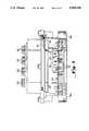
- FIG. 4is a perspective view of a tap unit which includes an embodiment of the present invention.
- FIG. 5is a cut-away side plan view of the tap unit shown in FIG. 4.
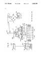
- FIG. 6is a schematic diagram, partially in block diagram form, of circuitry used in the tap unit shown in FIG. 4.
- FIG. 7is a schematic diagram of a signal coupler module suitable for use in the circuitry shown in FIG. 6.
- FIG. 8is a block diagram, partially in schematic diagram form of a signal splitter module suitable for use in the circuitry shown in FIG. 6.
- FIG. 9is a schematic diagram of a two-way splitter suitable for use in the splitter module shown in FIG. 8.
- FIG. 10is a schematic diagram of a portion of the switch circuitry shown in FIG. 8.
- the wideband RF tap described belowhas a modular construction. It includes three parts, a base unit, a directional coupler and a signal splitter.
- the base unitcouples two cable spans together. It conveys a power signal component and an RF signal component through the tap.
- the directional coupler moduleplugs into the base unit to separate a portion of the RF signal for use by the signal splitter.
- the signal splitter modulealso plugs into the base unit. Through this connection, it receives operational power and the portion of the RF signal separated by the directional coupler.
- the splitterdivides this signal among a number of RF connectors to provide each subscriber coupled to the tap with substantially the same signal level.
- the apparatus described belowincludes one type of base unit module, 12 different types of directional coupler modules and four different types of signal splitter modules. Any of 48 tap types commonly used by a cable operator may be built by combining one of the directional coupler modules and one of the signal splitter modules with the base unit module. Thus, using the system described below greatly reduces the inventory overhead for a cable television operator.
- the individual modules in the embodiment of the invention described beloware configured to simplify the repair of a defective tap unit.
- the RF signal and operational power signal passed by the base unit from one cable span to the nextare not significantly disrupted when the directional coupler module, the signal splitter module or both are removed from the tap unit. Consequently, fixing one broken tap in the distribution system will not generate complaints from other subscribers whose service would otherwise be disrupted.
- the directional coupler modulesince the directional coupler module does not convey operational power, it may be designed to be a relatively small module, using inexpensive low-power components. This coupler module design also reduces potential electric shock hazards to service personnel relative to a coupler which passes electrical power.
- the signal splitter modules used in this embodiment of the inventionreceive both RF and operational power signals via a single connector from the base unit.
- These modulesare designed with power efficient complementary metal-oxide-semiconductor (CMOS) technology, thus, its power requirements are relatively low. This design feature reduces the potential electric shock hazard to service personnel and reduces the power requirements for the cable operator.
- CMOScomplementary metal-oxide-semiconductor
- a signal splitter modulemay include between two and eight subscriber output terminals.
- the splitter moduleincludes circuitry which allows any of these output terminals to be disconnected from the cable system via a command sent along the cable system from a remote location.
- the shut-off operationis accomplished using RF relay circuitry. This circuitry strongly attenuates signals provided to the subscriber and terminates the output port of the splitter. This prevents amplitude response changes at other subscriber ports and maintains signal input impedance.
- FIG. 1labeled Prior Art, is a block diagram of one branch line of a conventional cable television distribution network.
- An RF signalwhich may occupy a band of frequencies between 5 MHz and 550 MHz and a 60 volt alternating current (AC) power signal are generated at the head end (not shown) of the cable network and applied to a feeder cable 110.
- the feeder cableis connected to the input port of a coupling tap (C-tap) 112.
- Power supply circuits(not shown) which increase the level of the operational power signal are also inserted in the cable span as necessary.
- the C-tap 112separates a relatively small portion of the signal provided by the feeder cable 110 and provides the separated portion to subscribers via terminals 112a and 112b.
- the remainder of the signal provided by the feeder cable 110is passed to one end of a cable span 114 coupled to the output port of the C-tap 112.
- the other end of the cable span 114is coupled to the input port of a C-tap 116.
- This C-tapalso separates a small portion of the signal applied to its input port and provides this separated portion to subscribers.
- the remainder of the signalis passed through the tap to a cable span 117.
- S-tapsplitter tap
- An S-tapincludes two-way signal splitter circuitry in place of the directional coupler.
- the S-tap 118provides one-half of the signal applied to its input port to the subscribers and provides the other half to an RF amplifier 120.
- the amplifier 120increases the amplitude of the RF signal to a level sufficient to drive another string of taps.
- the noise level of the available signalis too great to permit further amplification.
- the signal provided by an S-tapis applied to a terminating tap.
- thisis illustrated by the S-tap 128 and terminating tap 130.
- a terminating tapmay be formed, for example, by replacing the two-way splitter of an S-tap with a conductor.
- each of the tapsis passive, that is to say, the taps merely channel signals from the cable network to the subscribers.
- the operational power signalis used only for RF amplifiers such as elements 120 and 122.
- Active tapsmay include circuitry for monitoring or disabling the signal delivered to the subscribers and for establishing a communication link between the subscriber and the head-end of the network.
- FIG. 2labeled Prior Art, illustrates the structure of a typical passive C-tap.
- the combined operational power and RF signalis applied to the tap via a shielded transmission cable 208.
- the operational power component of the signalis passed to an output cable 209 via a inductor 210.
- the inductor 210is selected to provides a relatively large impedance to the RF signal component and a negligible impedance to the operational power signal, which, in the present embodiment of the invention is a 60 Hz AC signal.
- the RF component signalis passed from the input cable 208 to the output cable 209 by a capacitor 212, a directional coupler 216 and a capacitor 214.
- the capacitors 212 and 214are selected to have a capacitance that provides a relatively high impedance to the operational power signal and a negligible impedance to the RF signal.
- the directional coupler 216divides the signal applied to its input port into two portions. One portion is passed through to the output cable and the other portion is applied to signal splitter circuitry 218.
- the circuitry 218may include, for example, a network of hierarchically coupled two-way splitters which successively halve the signal provided by the directional coupler 218 to produce eight subscriber signals.
- the subscriber signalsare provided by the splitter circuitry via signal transmission cables 220. As shown in FIG. 2, the ground connection provided by the cable shield 208s is used to ground the shields of the output cable 209 and each of the subscriber cables 220.
- FIG. 3labeled Prior Art, is a block diagram, partially in schematic diagram form of an active C-tap.
- the circuitry shown in FIG. 3is a simplified diagram of tap circuitry described in U.S. Pat. No. 4,450,481 entitled "TAMPER-RESISTANT, EXPANDABLE COMMUNICATIONS SYSTEM,” which is hereby incorporated by reference.
- This unitis called an active tap because it may be programmed, inter alia, to block signals provided to an individual subscriber.
- the C-tap shown in FIG. 3comprises three component parts, a housing which includes RF connectors 310 and 312, a signal coupling circuit 311 and a signal splitter 321.
- the signal coupling circuit 311connects to cable spans in the distribution network by the RF connectors 310 and 312. When the network 311 is removed from this C-tap, The RF and power connections are broken to taps farther down the branch of the cable network.
- the signal splitter 321connects to the signal coupling circuit via three connectors: an RF connector 324 and two operational power connectors SG and SP.
- the signal coupling circuit 311includes a inductor 313, capacitors 314 and 316 and a directional coupler 318 which correspond to the respective elements 210, 212, 214 and 216 of the passive C-tap shown in FIG. 2.
- the inductor 320is included in the coupling circuitry 311 to pass the power signal component from the output port of the coupling circuitry 311 to the power input connector SP of the signal splitting circuitry 321.
- the connector SG of the signal splitting circuitry 321is coupled to the shield 310s of the cable 310 as a source of reference potential (e.g. ground).
- the signal splitter circuitry 321includes a power supply circuit which converts the AC power signal provided at the terminals SG and SP into a direct current (DC) operating potential V. This operating potential is used by components of the signal splitting circuitry 321 as set forth below.
- DCdirect current
- the main component of the circuitry 321is a hierarchical signal splitter 326.
- This splittermay be identical to the splitter 218 described above in reference to FIG. 2.
- the output signals of the splitter 326are applied provided to subscribers via a switch network 328.
- the network 328includes one RF switch for each signal provided by the splitter 326. These RF switches are controlled by a microprocessor 332 which receives control signals from the cable distribution system via a receiver 330. In the system shown in FIG. 3, these signals are modulated onto a carrier signal having a frequency outside of the band of frequencies occupied by the RF television signals.
- the signals provided by the receiver 330control the switch 328 to selectively provide RF signal to ones of the subscriber taps 430.
- a tap having the ability to remotely connect or disconnect a subscriberis known in the industry as an addressable tap.
- FIG. 4is a perspective view of the exemplary tap.
- the tapincludes three modules, a base unit 410, a plug-in directional coupler 416 and a plug-in splitter 418.
- Input signalsare applied to the tap via an RF connector 408.
- a mother-board assembly 412 in the base unit 410separates the operational power component from the input signals and channels this signal to an output RF connector 409 (shown in FIG. 5).
- the assembly 412includes connectors 422 for coupling the directional coupler 416 to the base unit.
- the directional coupler module 416includes connecting pins 420 aligned to fit the connectors 422 on the mother-board assembly 412.
- An RF connector 426is also included on the mother-board 412 to couple the splitter module to the tap. This connector joins with a connector 424 on the splitter module 418. As illustrated in FIG.
- the directional coupler module 416 and the signal splitter module 418are configured for easy removal from the mother-board assembly 412.
- the circuitry for the splitter module 418is implemented on a printed circuit board 510 (shown in FIG. 5) mounted beneath an RF shield 42B. Subscriber signals are provided by RF connectors 430 mounted on the front of the splitter module 418.
- FIG. 5is a cut-away side-plan view of the tap shown in FIG. 4. This Figure illustrates the physical coupling of the base unit directional coupler and splitter modules when the tap is assembled.
- FIG. 6shows circuitry suitable for use as the mother-board assembly 412.
- the directional coupler module 416 and splitter module 418are shown as blocks to provide a context for describing the assembly 412.
- signals from the cable networkare applied to the tap through the RF connector 408.
- the 60 Hz AC power signalis passed through an inductor 613 to the output RF connector 409.
- the inductor 613is selected to provide negligible impedance to the 60 Hz power signal component of the cable television signal and to provide a relatively high impedance to the RF signal component.
- the RF component of the cable television signalis passed through a coupling capacitor 614 to an output connector 422i of the mother-board assembly.
- This output connectoris configured to receive an input connector 420i of the directional coupler 416.
- the directional coupler 416passes a portion of the RF signal to an output connector 420c which is coupled to the splitter module 418. However, most of the RF signal is passed through the coupler 416 to an output connector 420o.
- Connectors 422c and 422o on the mother-board assemblyare configured to receive the connectors 420c and 420o of the directional coupler module.
- RF signals applied to the connector 422oare passed through a capacitor 616 to the output RF connector 409 of the tap.
- the RF component of the cable television signalmay be passed through the tap by a resistor 612 or, alternatively by a switch 613 shown in phantom.
- the resistor 612 used in this embodiment of the inventionhas an impedance of 75 ohms. This impedance is significantly greater than the effective series impedance of any of the directional coupler modules 416. Consequently, when a directional coupler module is plugged into the mother board assembly, the resistor 612 passes only a relatively small portion of the RF signal.
- the switch 613represents an alternative method of passing the RF signal through the tap when the directional coupler is removed.
- the switch 613 shown in this alternative embodiment of the inventionmay be, for example, a normally closed switch which is held open by the directional coupler when it is plugged into the tap.
- the mother-board assembly shown in FIG. 6receives an RF signal from the directional coupler 412 via the connector 422d. This signal is coupled through a capacitor 618 to the RF connector 426 which supplies the RF signal and an AC operating power signal to the splitter module 418.
- the AC power signalis passed through an inductor 620 and a inductor 630. These elements are selected to present a relatively small impedance to the 60 Hz AC power signal component and a relatively large impedance to the RF signal component of the cable television signal.
- the inductor 630includes a primary winding 628 and a secondary winding 631. Each winding consists of a few (less than 10) turns of wire. The windings are wrapped around a ferrite core.
- a resistor 626is coupled across the primary winding to reduce the magnitude of any change in impedance due to series self resonance of the inductor 630.
- the power signal passing circuitryincludes a capacitor 622 coupled between ground and the junction of the inductor 620 and the inductor 630. This capacitor sets the resonant frequency of the network which also includes the inductor 620 and the inductor 630 to a frequency below of the band of frequencies occupied by the RF signal component.
- a varistor 624is coupled in parallel with the capacitor 622 to shunt voltage surges to ground. This resistor protects the circuitry in the splitter module from voltage surges produced, for example, by nearby lightning strikes.
- the power passing circuitrycouples the AC power signal to the RF signal at the junction of the capacitor 618 and RF connector 426. This combined signal is applied to the splitter module 41 to produce RF signals to be provided to the subscribers via the RF connectors 430. Circuitry suitable for use as the splitter module 418 is described below in reference to FIGS. 8, 9 and 10.
- FIG. 7is a block diagram of circuitry suitable for use as the directional coupler module 416.
- the central element of the circuitry shown in FIG. 7is a coupling transformer 710.
- the transformer 710includes a current transformer 712 and a voltage transformer 714.
- the primary winding 711 of the current transformer 712is coupled between an input connector 420i and an output connector 420o.
- the primary winding 715 of the voltage transformer 714is coupled between the output connector 420o and ground.
- the output signals of the two transformersare combined and applied to a voltage divider network formed by resistors 732, 734 and 736.
- the resistor 734may be replaced by a conductor as indicated in phantom by the jumper 738.
- the resistor 736is coupled in parallel with the coupler output connector 420c.
- the voltage divider networkmatches the output impedance of the coupler to the input impedance of its load (i.e. to the circuitry coupled via the connector 420c).
- the resistor networkalso provides a method of adjusting the amount of power transferred to the load so that a defined tap-loss value may be realized.
- the resistor 730is included in the coupler to terminate the grounded end of the secondary winding 716 of the transformer 714. This resistor reduces the level of signals that may propagate from the output 420c and interfere with the RF component of the cable television signal.
- the circuitry shown in FIG. 7is known as a directional coupler because it allows signals to propagate from the connector 420i to the coupler connector 420c more efficiently than from the connector 420c to the connector 420o.
- the capacitor 728is included to adjust the circuit impedance at the point at which the transformer 710 is attached.
- the capacitors 722, 724, and 726are included in the circuitry to adjust the impedance presented at the respective connectors 420i, 420o and 420c. Each of these capacitors may have a capacitance of between 1 pf and 10 pf. The exact value used depends on the inductance of the various windings of the transformer 710.
- Coupler moduleAs set forth above, 12 different types of coupler module are provided for use in this embodiment of the invention.
- the couplersare identified by their tap-loss values, where tap-loss is defined as the negative of ten times the logarithm of the ratio of the power provided at the connector 420i to the input power provided at the connector 420c. Tap-loss is expressed in units of decibels (dB).
- the 12 types of coupler modulehave tap-loss values of between 0 dB and 33 dB in steps of 3 dB. These tap-loss values are exemplary, it is contemplated that couplers may be made having tap-loss values in increments of 1 dB.
- the 0 dB coupleris implemented as a conductor joining the terminals 420i and 420c. This coupler is used in a terminating tap such as the tap 130 shown in FIG. 1.
- the 3 dB coupler used in this embodiment of the inventionis a two-way splitter such as that shown in FIG. 9.
- the tap-loss value for this type of coupleris approximately 4 dB.
- the other ten couplershaving tap loss values between 6 dB and 33 dB, are directional couplers of the type shown in FIG. 7.
- a directional couplermay be designed to have a specific tap-loss value by selecting the number of turns of each of the windings 711, 713, 715 and 716 and the values of the resistors 732, 734 and 736.
- One skilled in the art of designing RF circuitrywould be able to construct suitable circuitry without undue experimentation.
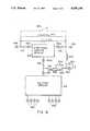
- FIG. 8is a block diagram, partially in schematic diagram form of circuitry suitable for use as the splitter module 418.
- this circuitryincludes a hierarchical signal splitting network which divides the RF signal energy into eight substantially equal parts. These eight signals are applied to a switching network 836 which, under control of a microprocessor 842, selectively provides the signals to subscribers via the RF connectors 430.
- the microprocessorreceives command signals from the head-end of the cable system via a receiver 840.
- the tap unit shown in FIG. 6is an addressable tap. It is contemplated that a passive tap unit may be used in place of the tap unit shown in FIG. 8.
- the command signals used in this embodiment of the inventionare frequency-shift keyed (FSK) signals that modulate a carrier having a frequency of approximately 51.5 MHz. This signal is outside of the band of frequencies occupied by the modulated television signals.
- FSKfrequency-shift keyed
- These command signalsare demodulated by a receiver 840 which provides its output signal to the microprocessor 842.
- these commandscondition the microprocessor to selectively disable or enable a subscriber connection to the cable network.
- the status of each subscriber connectionis stored in a nonvolatile memory 844 which is coupled to the microprocessor 842. Operational power for the switching network 836, the microprocessor 842, the memory 844 and the receiver 840 is provided by a power supply 814.
- the combined RF and operational power signalis applied to the splitter module 418 via the RF connector 424.
- This signalis applied to an inductor 810 which passes the operational power signal to the relative exclusion of the RF signal.
- This power signalis applied to a first AC terminal, A1, of a bridge rectifier 812.
- Another AC terminal, A2is coupled to the signal ground, provided by the shield connection of the RF connector 424.
- the bridge rectifier 812produces a DC operating potential between two terminals, D1 and D2.
- the potential at terminal D1is approximately +60 volts above the potential at terminal D2.
- the terminals D1 and D2are coupled to the power supply circuitry 814.
- the potential at terminal D2is defined as circuit ground. Different ground symbols are used to represent circuit ground and signal ground to emphasize that the circuit ground is "floating" with respect to signal ground.
- the circuit and signal groundsare coupled for AC signals by a coupling capacitor 816.
- the power supply circuitry 814may be of conventional design and is not described in detail. This circuitry provides a filtered signal VR having a potential with respect to the circuit ground of, for example, 60 volts. It also produces a voltage regulated signal, VL, which may have a potential of, for example five volts with respect to the circuit ground.
- the signal VRis used as an operational power signal by the switch network 836.
- the signal VLis used as an operational power signal by the receiver 840, microprocessor 842 and the non-volatile memory circuit 844.
- the RF component of the signal applied to the connector 424is passed by a capacitor 818 to a two-way splitter 822.
- Exemplary two-way splitter circuitryis shown in FIG. 9.
- the splitter 822divides the signal applied to its input terminal, IN, into two approximately equal parts and provides these two signals at output terminals OUT1 and OUT2.
- the splitter moduleincludes seven two-way splitters arranged hierarchically so that the two output terminals of the splitter 822 are coupled to input terminals of respective splitters 824 and 826.
- the splitter 824is coupled to the splitters 828 and 830, while the output terminals of the splitter 826 are coupled to the respective splitters 832 and 834.
- the output terminals of the splitters 828, 830, 832 and 834are coupled to the switch network 836.
- the switch network 836includes eight switch elements, 836a through 836h, one for each of the eight output signals provided by the four two-way splitters 834, 832, 830 and 828, respectively.
- Each switch elementis separately controlled by the microprocessor 842 to selectively provide the television signal portion of the cable television signal to a subscriber via one of the RF connectors 430.
- An exemplary switch elementis described below in reference to FIG. 10.
- a splitter modulemay be configured to provide either two, four, six or eight subscriber connections.
- a single printed circuit boardis used to implement all four types of splitter module.
- a particular configurationis achieved by inserting or removing two jumpers, J1 and J2 (shown in phantom), and by selectively depopulating sections of the printed circuit board that are not used in a given configuration.
- the exemplary splitter shown in FIG. 8may be configured to have two subscriber ports by inserting the two jumpers J1 and J2 and by omitting all components corresponding to the splitters 822, 824, 826, 828, 830 and 832 as well as the components for the switch elements 836c through 836h.
- a splitter module having four subscriber portswould have only jumper J1 inserted.
- Components corresponding to the splitters 822, 824, 828 and 830would be omitted as well as the components corresponding to the switch elements 836c through 836h.
- a six-port splitter modulewould have only the jumper J2 inserted.
- An eight-port splitter modulehas a fully populated printed circuit board and does not use either of the jumpers J1 or J2.
- FIG. 10is a schematic diagram of circuitry suitable for use as one of the switch elements 836a through 836h.
- RF signals provided by one of the two-way splitters 828, 830, 832 and 834are applied to a signal input terminal of an RF relay 1010.
- the relayincludes a coil 1011 which may be energized or de-energized to connect the signal input terminal to one terminal of a coupling capacitor 1014 or to a terminating resistor 1012, respectively.
- the other terminal of the capacitor 1014is coupled to one of the subscriber RF connectors 430.
- the relay coil 1011is energized by circuitry which includes a driver transistor 1028. This transistor is biased point of fixed operating current by an emitter resistor 1029 and a zener diode 1032. A control signal from the microprocessor 842 is applied to the base terminal of the transistor 1028 via a resistor 1030. The amplitude of this control signal is limited by the zener diode 1032.
- the capacitors 1018, 1022, 1024 and 1026are bypass capacitors which conduct any RF signals which may be induced on the connections between the transistor 1028, the relay 1010 and the power supply 814 to ground. These RF signals may be induced by transmission line effects of these connections. It is contemplated that the three capacitors 1022, 1024 and 1026 may be replaced by a single capacitor.
- the capacitor 1034is a bypass capacitor which shunts any RF signals carried by the control signal to the circuit ground.
- a logic-one control signal from the microprocessor 842conditions the transistor 1028 to conduct the fixed current between its emitter and collector electrodes, energizing the relay independent of changes in VR.
- the microprocessor 842changes the signal to a logic-zero, the transistor ceases to conduct and the relay is de-energized.
- the control signal from the cable television networkconditions the microprocessor 842 to apply a logic-one control signal to the switch element which couples the subscriber to the network. This signal energizes the relay, connecting the subscriber.
- a logic-zero control signaldisconnects the subscriber.
- the cable connectionis terminated via the resistor 1012. This prevents amplitude response changes at the other subscriber ports and maintains the signal input impedance of the splitter module at a substantially constant value. Moreover, the signal to the former subscriber is reduced by approximately 60 dB.
- the RF relaysare more effective than conventional solid-state switches which may require more complex circuitry to achieve an equivalent level of attenuation and which may also produce undesirable intermodulation products between the RF carriers of the cable television signal.
- subscriber informationis stored in the nonvolatile memory 844 of the tap unit, this information is not lost when the tap loses operational power. Each subscriber is automatically reconnected when operational power returns.
- a modular tap for an RF signal distribution networkhas been described.
- This apparatushas significant advantages over prior systems since it reduces the number and size of the components used by a cable television operator to build and maintain a distribution system.
- the apparatus described abovehas significant safety advantages since only relatively low levels of operational power are broken when components of the tap unit are removed for servicing.
Landscapes
- Engineering & Computer Science (AREA)
- Multimedia (AREA)
- Signal Processing (AREA)
- Two-Way Televisions, Distribution Of Moving Picture Or The Like (AREA)
- Details Of Television Systems (AREA)
Abstract
Description
______________________________________ Resistors: 612, 730, 1012 75ohm 624 1.1K ohm 626 102v varistor 838 470920, 1016 10 ohm 1029 130 ohm 1030 1 K ohm Capacitors: 614, 616, 618, 622, 818, 1014 .01 ohm microfarad 728 1.5picofarad 816 .02microfarad 910 1.8picofarad 913 3.3picofarad 914 4.3picofarad 918 5picofarad 922 21022, 1026 270 picofarad 1024, 1034 1000 picofarad Semiconductors: 1020 picofarad 1N4004 1028MPSA42 1034 2.4 volt zener diode Relay: 1010 UM1-48W-K Mfd. by Takamisawa Corp. ______________________________________
Claims (10)
Priority Applications (1)
| Application Number | Priority Date | Filing Date | Title |
|---|---|---|---|
| US07/331,687US5058198A (en) | 1989-03-31 | 1989-03-31 | Radio frequency tap unit which can be reconfigured with minimal disruption of service |
Applications Claiming Priority (1)
| Application Number | Priority Date | Filing Date | Title |
|---|---|---|---|
| US07/331,687US5058198A (en) | 1989-03-31 | 1989-03-31 | Radio frequency tap unit which can be reconfigured with minimal disruption of service |
Publications (1)
| Publication Number | Publication Date |
|---|---|
| US5058198Atrue US5058198A (en) | 1991-10-15 |
Family
ID=23294942
Family Applications (1)
| Application Number | Title | Priority Date | Filing Date |
|---|---|---|---|
| US07/331,687Expired - LifetimeUS5058198A (en) | 1989-03-31 | 1989-03-31 | Radio frequency tap unit which can be reconfigured with minimal disruption of service |
Country Status (1)
| Country | Link |
|---|---|
| US (1) | US5058198A (en) |
Cited By (74)
| Publication number | Priority date | Publication date | Assignee | Title |
|---|---|---|---|---|
| US5382971A (en)* | 1992-08-19 | 1995-01-17 | U.S. Philips Corporation | Television signal cable distribution system and assembly of elements for constituting such a system |
| US5386226A (en)* | 1992-08-19 | 1995-01-31 | U.S. Philips Corporation | Connection unit for a television signal distribution system |
| EP0652675A1 (en)* | 1993-11-05 | 1995-05-10 | Yee, Bark-Lee | CATV signal splitter |
| US5434610A (en)* | 1992-07-13 | 1995-07-18 | Scientific-Atlanta, Inc. | Methods and apparatus for the reconfiguration of cable television systems |
| US5550824A (en)* | 1995-02-24 | 1996-08-27 | Harris Corporation | RF signal distribution scheme |
| US5555015A (en)* | 1995-03-20 | 1996-09-10 | Intrinzix Technologies, Inc. | Wireless two way transmission between center and user stations via a relay |
| WO1996029782A1 (en)* | 1995-03-21 | 1996-09-26 | Scientific-Atlanta, Inc. | Non-interruptible tap and method |
| WO1996029825A1 (en)* | 1995-03-22 | 1996-09-26 | Scientific-Atlanta, Inc. | Distribution of ac and rf signals to taps |
| WO1997015096A1 (en)* | 1995-10-18 | 1997-04-24 | J.E. Thomas Specialties Limited | Top exit coupler |
| US5632647A (en)* | 1994-10-17 | 1997-05-27 | Lucent Technologies Inc. | RF/power tap |
| US5635881A (en)* | 1995-04-20 | 1997-06-03 | J.E. Thomas Specialties Limited | Switched pedestal/aerial port coaxial cable distribution network |
| WO1997024878A1 (en)* | 1995-12-29 | 1997-07-10 | General Instrument Corporation | System to reduce gain variance and ingress in catv return transmissions |
| US5675300A (en)* | 1995-10-18 | 1997-10-07 | J.E. Thomas Specialties Limited | Top exit coupler |
| EP0800242A4 (en)* | 1994-12-22 | 1998-03-25 | Maspro Denko Kk | High-frequency signal branching device |
| US5768084A (en)* | 1996-07-25 | 1998-06-16 | Tii Industries, Inc. | Combination coaxial surge arrestor/power extractor |
| US5805202A (en)* | 1995-10-20 | 1998-09-08 | Sensormatic Electronics Corporation | Automatic video cable compensation system |
| US5834989A (en)* | 1995-04-21 | 1998-11-10 | J.E. Thomas Specialties Limited | Circuitry for use with coaxial cable distribution networks with a ground plane near the ports |
| US5909154A (en)* | 1997-06-02 | 1999-06-01 | Antec Corporation | Broadband signal tap with continuity bridge |
| US5909155A (en)* | 1996-12-06 | 1999-06-01 | Adc Telecommunications, Inc. | RF splitter/combiner module |
| USD410630S (en) | 1998-06-29 | 1999-06-08 | Uro Denshi Kogyo Kabushiki Kaisha | Tap off for a cable television |
| US5920239A (en)* | 1997-10-07 | 1999-07-06 | Scientific-Atlanta, Inc. | Multiple dwelling unit tap off including an equalizer circuit |
| US5945634A (en)* | 1995-04-24 | 1999-08-31 | Raychem Corporation | Coaxial cable tap with slitted housing and non-piercing tap insert |
| US5973262A (en)* | 1995-10-13 | 1999-10-26 | Maspro Denkoh Co., Ltd. | Multi-tap distribution apparatus |
| US5990759A (en)* | 1996-06-18 | 1999-11-23 | Maspro Denkoh, Co., Ltd. | Directional coupler rotatable around a fulcrum |
| US6025760A (en)* | 1998-05-01 | 2000-02-15 | Tang; Danny Q. | Tool for shunting a cable multi-tap |
| US6031432A (en)* | 1997-02-28 | 2000-02-29 | Schreuders; Ronald C. | Balancing apparatus for signal transmissions |
| US6031300A (en)* | 1997-03-28 | 2000-02-29 | Bell Atlantic Networks Services, Inc. | Bridge tap remover |
| US6069797A (en)* | 1998-12-29 | 2000-05-30 | Motorola, Inc. | Power distribution assembly |
| JP3076960B2 (en) | 1995-06-23 | 2000-08-14 | マスプロ電工株式会社 | Switch |
| USH1858H (en)* | 1998-06-26 | 2000-09-05 | Scientific-Atlanta, Inc. | Radio frequency sensed, switched reverse path tap |
| US6130703A (en)* | 1998-02-10 | 2000-10-10 | Scientific-Atlanta, Inc. | Local status monitoring of taps in a cable television system |
| EP1022815A3 (en)* | 1999-01-11 | 2000-12-20 | General Instrument Corporation | Catv directional component with signal reversing capability and method |
| US6289210B1 (en) | 1996-12-06 | 2001-09-11 | Adc Telecommunications, Inc. | Rf circuit module |
| US20020174435A1 (en)* | 2001-02-27 | 2002-11-21 | Hillel Weinstein | System, apparatus and method for expanding the operational bandwidth of a communication system |
| US6560778B1 (en)* | 1999-03-29 | 2003-05-06 | Masprodenkoh Kabushikikaisha | Tap device of cable broadcasting system |
| US6570465B2 (en)* | 2000-12-01 | 2003-05-27 | Danny Q. Tang | Multi-tap kit for cable television systems |
| US6580336B1 (en)* | 1998-12-31 | 2003-06-17 | At&T Corp. | Method and apparatus for providing uninterrupted service in a hybrid fiber coaxial system |
| US6624721B1 (en)* | 2000-10-13 | 2003-09-23 | Tektronix, Inc. | Apparatus for acquiring a signal from an intermediate point on a series impedance source terminated unidirectional transmission line |
| US20040059838A1 (en)* | 2000-12-05 | 2004-03-25 | Rainer Schenkyr | Distribution of data |
| US20040139476A1 (en)* | 1999-11-18 | 2004-07-15 | Bacon Kinney C. | Systems and methods of decoding and processing transactions for an addressable cable television tap |
| US6811430B1 (en) | 2003-11-04 | 2004-11-02 | Tyco Electronics Corporation | Toggle type telecommunications terminal blocks including a travel limit member |
| US20040219815A1 (en)* | 2003-04-30 | 2004-11-04 | Thompson Roy Keller | Toggle type telecommunications terminal blocks |
| EP1505833A3 (en)* | 2003-08-06 | 2005-07-13 | Xtend Networks Ltd. | A wideband catv tap device |
| US20050155082A1 (en)* | 2001-02-27 | 2005-07-14 | Hillel Weinstein | Device, system and method for connecting a subscriber device to a wideband distribution network |
| US20050206475A1 (en)* | 2002-05-02 | 2005-09-22 | Yeshayahu Strull | Wideband catv signal splitter device |
| US20050210529A1 (en)* | 2004-03-22 | 2005-09-22 | C-Cor.Net Corp. | Coaxial communication active tap device and distribution system |
| US20060101501A1 (en)* | 2000-10-16 | 2006-05-11 | Zeev Orbach | System, device and method of expanding the operational bandwidth of a communication infrastructure |
| US7110534B1 (en) | 2000-07-27 | 2006-09-19 | Tyco Electronics Corporation | Terminal blocks and methods for making and breaking connections in a telecommunication conductor |
| US20060279379A1 (en)* | 2005-06-13 | 2006-12-14 | Gale Robert D | Electric signal splitters |
| US20070063790A1 (en)* | 2005-05-19 | 2007-03-22 | Yeshayahu Strull | Wideband CATV signal splitter device |
| EP1780828A1 (en)* | 2005-10-28 | 2007-05-02 | Mitsubishi Electric Information Technology Centre Europe B.V. | Frequency diplexer with an input port and a first and a second output ports |
| US20070257025A1 (en)* | 2006-05-04 | 2007-11-08 | Nordstrom Robert A | Method and apparatus for probing |
| US20080040764A1 (en)* | 2001-07-20 | 2008-02-14 | Hillel Weinstein | System, apparatus and method for expanding the operational bandwidth of a communication system |
| US20080107016A1 (en)* | 2006-11-03 | 2008-05-08 | Tang Neil H | High-frequency uninterruptible signal and power bypass |
| US20080150546A1 (en)* | 2005-06-15 | 2008-06-26 | Gale Robert D | Continuity tester adaptors |
| US20090119735A1 (en)* | 2000-10-16 | 2009-05-07 | Oleg Dounaevski | Wideband node in a catv network |
| US20090133095A1 (en)* | 2007-11-20 | 2009-05-21 | Commscope, Inc. Of North Carolina | Addressable Tap Units for Cable Television Networks and Related Methods of Remotely Controlling Bandwidth Allocation in Such Networks |
| US20100173523A1 (en)* | 2009-01-02 | 2010-07-08 | Gavriel Magnezi | Dual-direction connector and method for cable system |
| US20100244980A1 (en)* | 2009-03-30 | 2010-09-30 | Olson Thomas A | Method and apparatus for a self-terminating signal path |
| WO2010133884A1 (en)* | 2009-05-22 | 2010-11-25 | Technetix Group Limited | Signal splitter for use in moca/catv networks |
| US20120278850A1 (en)* | 2011-04-28 | 2012-11-01 | Cable Vision Electronics Co. | Rf directional coupler circuit assembly for matching high frequency cable tv apparatus |
| US20150237683A1 (en)* | 2012-10-22 | 2015-08-20 | Officine Di Cartigliano Spa | Device for generating an alternate radiofrequency electromagnetic field, control method and plant using such device |
| US20170201001A1 (en)* | 2014-07-16 | 2017-07-13 | Technetix B.V. | Cable Tap |
| US10050328B2 (en)* | 2015-11-27 | 2018-08-14 | Technetix B.V. | Cable tap |
| WO2019051448A1 (en)* | 2017-09-11 | 2019-03-14 | Antronix Inc. | Power passing directional coupler having a split ferrite element |
| US20190253663A1 (en)* | 2018-02-13 | 2019-08-15 | Cable Vision Electronics Co., Ltd | Cable television apparatus using coupled-line directional coupler implementing high pass filter function |
| US10784664B2 (en)* | 2018-03-05 | 2020-09-22 | Cisco Technology, Inc. | Three-piece electronics enclosure |
| US11038250B1 (en)* | 2018-10-23 | 2021-06-15 | MiniRF, Inc. | Directional coupler assembly |
| US11044440B2 (en) | 2019-11-04 | 2021-06-22 | Times Fiber Communications, Inc. | Universal MoCA gateway splitter |
| US11437694B2 (en)* | 2020-03-04 | 2022-09-06 | Holland Electronics, Llc | Uninterruptable tap |
| IT202100013946A1 (en)* | 2021-05-27 | 2022-11-27 | Emme Esse S P A | DERIVATOR FOR TELEVISION SYSTEMS |
| US20230078603A1 (en)* | 2020-03-04 | 2023-03-16 | Holland Electronics Llc | Uninterruptable tap |
| US11665314B2 (en)* | 2020-04-27 | 2023-05-30 | Cable Vision Electronics Co., Ltd. | Signal splitting device |
| US12160073B1 (en)* | 2022-06-14 | 2024-12-03 | Lockheed Martin Corporation | Symmetric radio frequency coaxial splitters |
Citations (5)
| Publication number | Priority date | Publication date | Assignee | Title |
|---|---|---|---|---|
| US4367557A (en)* | 1975-08-09 | 1983-01-04 | Stern Joseph L | Wired broadcasting systems |
| US4450481A (en)* | 1981-08-25 | 1984-05-22 | E-Com Corporation | Tamper-resistant, expandable communications system |
| US4578702A (en)* | 1984-05-31 | 1986-03-25 | American Television & Communications Corporation | CATV tap-off unit with detachable directional coupler |
| US4755776A (en)* | 1987-03-06 | 1988-07-05 | Broadband Networks, Inc. | Tap device for broadband communications systems |
| US4810898A (en)* | 1987-07-17 | 1989-03-07 | Am Communications, Inc. | RF network isolation switch |
- 1989
- 1989-03-31USUS07/331,687patent/US5058198A/ennot_activeExpired - Lifetime
Patent Citations (5)
| Publication number | Priority date | Publication date | Assignee | Title |
|---|---|---|---|---|
| US4367557A (en)* | 1975-08-09 | 1983-01-04 | Stern Joseph L | Wired broadcasting systems |
| US4450481A (en)* | 1981-08-25 | 1984-05-22 | E-Com Corporation | Tamper-resistant, expandable communications system |
| US4578702A (en)* | 1984-05-31 | 1986-03-25 | American Television & Communications Corporation | CATV tap-off unit with detachable directional coupler |
| US4755776A (en)* | 1987-03-06 | 1988-07-05 | Broadband Networks, Inc. | Tap device for broadband communications systems |
| US4810898A (en)* | 1987-07-17 | 1989-03-07 | Am Communications, Inc. | RF network isolation switch |
Cited By (117)
| Publication number | Priority date | Publication date | Assignee | Title |
|---|---|---|---|---|
| US5434610A (en)* | 1992-07-13 | 1995-07-18 | Scientific-Atlanta, Inc. | Methods and apparatus for the reconfiguration of cable television systems |
| US5386226A (en)* | 1992-08-19 | 1995-01-31 | U.S. Philips Corporation | Connection unit for a television signal distribution system |
| US5382971A (en)* | 1992-08-19 | 1995-01-17 | U.S. Philips Corporation | Television signal cable distribution system and assembly of elements for constituting such a system |
| EP0652675A1 (en)* | 1993-11-05 | 1995-05-10 | Yee, Bark-Lee | CATV signal splitter |
| US5632647A (en)* | 1994-10-17 | 1997-05-27 | Lucent Technologies Inc. | RF/power tap |
| US5990758A (en)* | 1994-12-22 | 1999-11-23 | Masprodenkoh Kabushikikaisha | High-frequency signal branching device |
| EP0800242A4 (en)* | 1994-12-22 | 1998-03-25 | Maspro Denko Kk | High-frequency signal branching device |
| US5550824A (en)* | 1995-02-24 | 1996-08-27 | Harris Corporation | RF signal distribution scheme |
| US5555015A (en)* | 1995-03-20 | 1996-09-10 | Intrinzix Technologies, Inc. | Wireless two way transmission between center and user stations via a relay |
| US5675372A (en)* | 1995-03-20 | 1997-10-07 | Intrinzix Technologies, Inc. | Wireless two-way communication system between center and user stations |
| WO1996029782A1 (en)* | 1995-03-21 | 1996-09-26 | Scientific-Atlanta, Inc. | Non-interruptible tap and method |
| WO1996029781A1 (en)* | 1995-03-21 | 1996-09-26 | Scientific-Atlanta, Inc. | Non-interruptible tap and method |
| US5781844A (en)* | 1995-03-22 | 1998-07-14 | Scientific-Atlanta, Inc. | Method and apparatus for distributing a power signal and an RF signal |
| US5581801A (en)* | 1995-03-22 | 1996-12-03 | Scientific-Atlanta, Inc. | Apparatus for distributing RF signals and AC power to taps |
| WO1996029825A1 (en)* | 1995-03-22 | 1996-09-26 | Scientific-Atlanta, Inc. | Distribution of ac and rf signals to taps |
| AU704992B2 (en)* | 1995-04-20 | 1999-05-13 | J.E. Thomas Specialties Limited | Circuitry for use with coaxial cable distribution networks |
| EP0739052A3 (en)* | 1995-04-20 | 1997-12-10 | J.E. Thomas Specialties Limited | Circuitry for use with coaxial cable distribution networks |
| US5638035A (en)* | 1995-04-20 | 1997-06-10 | J. E. Thomas Specialties Limited | Coaxial cable distribution network having a reversible directional coupler |
| US5635881A (en)* | 1995-04-20 | 1997-06-03 | J.E. Thomas Specialties Limited | Switched pedestal/aerial port coaxial cable distribution network |
| US5834989A (en)* | 1995-04-21 | 1998-11-10 | J.E. Thomas Specialties Limited | Circuitry for use with coaxial cable distribution networks with a ground plane near the ports |
| US5945634A (en)* | 1995-04-24 | 1999-08-31 | Raychem Corporation | Coaxial cable tap with slitted housing and non-piercing tap insert |
| JP3076960B2 (en) | 1995-06-23 | 2000-08-14 | マスプロ電工株式会社 | Switch |
| US5973262A (en)* | 1995-10-13 | 1999-10-26 | Maspro Denkoh Co., Ltd. | Multi-tap distribution apparatus |
| US5796316A (en)* | 1995-10-18 | 1998-08-18 | J.E. Thomas-Specialties Limited | Top exit coupler |
| US5675300A (en)* | 1995-10-18 | 1997-10-07 | J.E. Thomas Specialties Limited | Top exit coupler |
| WO1997015096A1 (en)* | 1995-10-18 | 1997-04-24 | J.E. Thomas Specialties Limited | Top exit coupler |
| AU711308B2 (en)* | 1995-10-18 | 1999-10-07 | J.E. Thomas Specialties Limited | Top exit coupler |
| US5805202A (en)* | 1995-10-20 | 1998-09-08 | Sensormatic Electronics Corporation | Automatic video cable compensation system |
| US5835844A (en)* | 1995-12-29 | 1998-11-10 | General Instrument Corporation | Bidirectional CATV system having losses for equalizing upstream communication gain |
| WO1997024878A1 (en)* | 1995-12-29 | 1997-07-10 | General Instrument Corporation | System to reduce gain variance and ingress in catv return transmissions |
| US5990759A (en)* | 1996-06-18 | 1999-11-23 | Maspro Denkoh, Co., Ltd. | Directional coupler rotatable around a fulcrum |
| US5768084A (en)* | 1996-07-25 | 1998-06-16 | Tii Industries, Inc. | Combination coaxial surge arrestor/power extractor |
| US6650885B2 (en) | 1996-12-06 | 2003-11-18 | Adc Telecommunications, Inc. | RF circuit module |
| US5909155A (en)* | 1996-12-06 | 1999-06-01 | Adc Telecommunications, Inc. | RF splitter/combiner module |
| US20080014898A1 (en)* | 1996-12-06 | 2008-01-17 | Adc Telecommunications, Inc. | RF circuit module |
| US7197294B2 (en) | 1996-12-06 | 2007-03-27 | Adc Telecommunications, Inc. | RF circuit module |
| US20040018826A1 (en)* | 1996-12-06 | 2004-01-29 | Adc Telecommunications, Inc. | RF circuit module |
| US8244203B2 (en) | 1996-12-06 | 2012-08-14 | Atx Networks Corp. | RF circuit module |
| DE19782146B4 (en)* | 1996-12-06 | 2007-09-20 | ADC Telecommunications, Inc., Minnetonka | Radio frequency circuit module |
| US6289210B1 (en) | 1996-12-06 | 2001-09-11 | Adc Telecommunications, Inc. | Rf circuit module |
| US6031432A (en)* | 1997-02-28 | 2000-02-29 | Schreuders; Ronald C. | Balancing apparatus for signal transmissions |
| US6031300A (en)* | 1997-03-28 | 2000-02-29 | Bell Atlantic Networks Services, Inc. | Bridge tap remover |
| US5909154A (en)* | 1997-06-02 | 1999-06-01 | Antec Corporation | Broadband signal tap with continuity bridge |
| US5920239A (en)* | 1997-10-07 | 1999-07-06 | Scientific-Atlanta, Inc. | Multiple dwelling unit tap off including an equalizer circuit |
| US6130703A (en)* | 1998-02-10 | 2000-10-10 | Scientific-Atlanta, Inc. | Local status monitoring of taps in a cable television system |
| US6025760A (en)* | 1998-05-01 | 2000-02-15 | Tang; Danny Q. | Tool for shunting a cable multi-tap |
| USH1858H (en)* | 1998-06-26 | 2000-09-05 | Scientific-Atlanta, Inc. | Radio frequency sensed, switched reverse path tap |
| USD410630S (en) | 1998-06-29 | 1999-06-08 | Uro Denshi Kogyo Kabushiki Kaisha | Tap off for a cable television |
| US6069797A (en)* | 1998-12-29 | 2000-05-30 | Motorola, Inc. | Power distribution assembly |
| US6580336B1 (en)* | 1998-12-31 | 2003-06-17 | At&T Corp. | Method and apparatus for providing uninterrupted service in a hybrid fiber coaxial system |
| EP1022815A3 (en)* | 1999-01-11 | 2000-12-20 | General Instrument Corporation | Catv directional component with signal reversing capability and method |
| US7086078B1 (en) | 1999-01-11 | 2006-08-01 | General Instrument Corporation | CATV directional component with signal reversing capability and method |
| US6560778B1 (en)* | 1999-03-29 | 2003-05-06 | Masprodenkoh Kabushikikaisha | Tap device of cable broadcasting system |
| US20040139476A1 (en)* | 1999-11-18 | 2004-07-15 | Bacon Kinney C. | Systems and methods of decoding and processing transactions for an addressable cable television tap |
| US7743401B2 (en)* | 1999-11-18 | 2010-06-22 | Scientific-Atlanta, Inc. | Systems and methods of decoding and processing transactions for an addressable cable television tap |
| US7110534B1 (en) | 2000-07-27 | 2006-09-19 | Tyco Electronics Corporation | Terminal blocks and methods for making and breaking connections in a telecommunication conductor |
| US6624721B1 (en)* | 2000-10-13 | 2003-09-23 | Tektronix, Inc. | Apparatus for acquiring a signal from an intermediate point on a series impedance source terminated unidirectional transmission line |
| US20060101501A1 (en)* | 2000-10-16 | 2006-05-11 | Zeev Orbach | System, device and method of expanding the operational bandwidth of a communication infrastructure |
| US7904932B2 (en) | 2000-10-16 | 2011-03-08 | Xtend Networks Ltd. | Wideband node in a CATV network |
| US7616890B2 (en) | 2000-10-16 | 2009-11-10 | Xtend Networks Ltd. | System, device and method of expanding the operational bandwidth of a communication infrastructure |
| US20090119735A1 (en)* | 2000-10-16 | 2009-05-07 | Oleg Dounaevski | Wideband node in a catv network |
| US6570465B2 (en)* | 2000-12-01 | 2003-05-27 | Danny Q. Tang | Multi-tap kit for cable television systems |
| US7743170B2 (en)* | 2000-12-05 | 2010-06-22 | Hirschmann Electronic GmbH & Co. KG | Active tap for directing distribution of data over data transmission network |
| US20040059838A1 (en)* | 2000-12-05 | 2004-03-25 | Rainer Schenkyr | Distribution of data |
| US20050155082A1 (en)* | 2001-02-27 | 2005-07-14 | Hillel Weinstein | Device, system and method for connecting a subscriber device to a wideband distribution network |
| US7748023B2 (en) | 2001-02-27 | 2010-06-29 | Xtend Networks Ltd. | Device, system and method for connecting a subscriber device to a wideband distribution network |
| US20020174435A1 (en)* | 2001-02-27 | 2002-11-21 | Hillel Weinstein | System, apparatus and method for expanding the operational bandwidth of a communication system |
| US20080040764A1 (en)* | 2001-07-20 | 2008-02-14 | Hillel Weinstein | System, apparatus and method for expanding the operational bandwidth of a communication system |
| US20050206475A1 (en)* | 2002-05-02 | 2005-09-22 | Yeshayahu Strull | Wideband catv signal splitter device |
| US7138886B2 (en) | 2002-05-02 | 2006-11-21 | Xtend Networks Ltd. | Wideband CATV signal splitter device |
| US20040219815A1 (en)* | 2003-04-30 | 2004-11-04 | Thompson Roy Keller | Toggle type telecommunications terminal blocks |
| US6893280B2 (en) | 2003-04-30 | 2005-05-17 | Tyco Electronics Corporation | Toggle type telecommunications terminal blocks |
| EP1505833A3 (en)* | 2003-08-06 | 2005-07-13 | Xtend Networks Ltd. | A wideband catv tap device |
| US6811430B1 (en) | 2003-11-04 | 2004-11-02 | Tyco Electronics Corporation | Toggle type telecommunications terminal blocks including a travel limit member |
| US7721317B2 (en) | 2004-03-22 | 2010-05-18 | Arris Group | Coaxial communication active tap device and distribution system |
| US20050210529A1 (en)* | 2004-03-22 | 2005-09-22 | C-Cor.Net Corp. | Coaxial communication active tap device and distribution system |
| US8495696B1 (en)* | 2004-03-22 | 2013-07-23 | Arris Solutions, Inc. | Coaxial communication active tap device and distribution system |
| WO2005091980A3 (en)* | 2004-03-22 | 2009-01-08 | Broadband Royalty Corp | Coaxial communication active tap device and distribution system |
| US20070063790A1 (en)* | 2005-05-19 | 2007-03-22 | Yeshayahu Strull | Wideband CATV signal splitter device |
| US20060279379A1 (en)* | 2005-06-13 | 2006-12-14 | Gale Robert D | Electric signal splitters |
| US7830225B2 (en) | 2005-06-13 | 2010-11-09 | Gale Robert D | Electric signal splitters |
| US20080150546A1 (en)* | 2005-06-15 | 2008-06-26 | Gale Robert D | Continuity tester adaptors |
| US7830154B2 (en) | 2005-06-15 | 2010-11-09 | Gale Robert D | Continuity tester adaptors |
| US20070096846A1 (en)* | 2005-10-28 | 2007-05-03 | Mitsubishi Electric Corporation | Frequency diplexer with an input port and a first and a second output ports |
| EP1780828A1 (en)* | 2005-10-28 | 2007-05-02 | Mitsubishi Electric Information Technology Centre Europe B.V. | Frequency diplexer with an input port and a first and a second output ports |
| US7538634B2 (en) | 2005-10-28 | 2009-05-26 | Mitsubishi Electric Corporation | Frequency diplexer with an input port and a first and a second output ports |
| US20070257025A1 (en)* | 2006-05-04 | 2007-11-08 | Nordstrom Robert A | Method and apparatus for probing |
| US8067718B2 (en)* | 2006-05-04 | 2011-11-29 | Tektronix, Inc. | Method and apparatus for probing |
| US7807935B2 (en) | 2006-11-03 | 2010-10-05 | Antronix, Inc. | High-frequency uninterruptible signal and power bypass |
| US20080107016A1 (en)* | 2006-11-03 | 2008-05-08 | Tang Neil H | High-frequency uninterruptible signal and power bypass |
| US20090133095A1 (en)* | 2007-11-20 | 2009-05-21 | Commscope, Inc. Of North Carolina | Addressable Tap Units for Cable Television Networks and Related Methods of Remotely Controlling Bandwidth Allocation in Such Networks |
| WO2009067173A3 (en)* | 2007-11-20 | 2009-10-29 | Commscope Inc. Of North Carolina | Addressable tap units for cable television networks and related methods of remotely controlling bandwidth allocation in such networks |
| US8132222B2 (en) | 2007-11-20 | 2012-03-06 | Commscope, Inc. Of North Carolina | Addressable tap units for cable television networks and related methods of remotely controlling bandwidth allocation in such networks |
| US9065185B2 (en) | 2009-01-02 | 2015-06-23 | Xtend Networks Ltd. | Dual-direction connector and method for cable system |
| US20100173523A1 (en)* | 2009-01-02 | 2010-07-08 | Gavriel Magnezi | Dual-direction connector and method for cable system |
| US8082570B2 (en)* | 2009-03-30 | 2011-12-20 | John Mezzalingua Associates, Inc. | Method and apparatus for a self-terminating signal path |
| US20100244980A1 (en)* | 2009-03-30 | 2010-09-30 | Olson Thomas A | Method and apparatus for a self-terminating signal path |
| WO2010133884A1 (en)* | 2009-05-22 | 2010-11-25 | Technetix Group Limited | Signal splitter for use in moca/catv networks |
| US8810334B2 (en) | 2009-05-22 | 2014-08-19 | Technetix Group Limited | Signal splitter for use in MoCA/CATV networks |
| US20120278850A1 (en)* | 2011-04-28 | 2012-11-01 | Cable Vision Electronics Co. | Rf directional coupler circuit assembly for matching high frequency cable tv apparatus |
| US8587387B2 (en)* | 2011-04-28 | 2013-11-19 | Cable Vision Electronics Co., Ltd. | RF directional coupler circuit assembly for matching high frequency cable TV apparatus |
| US20150237683A1 (en)* | 2012-10-22 | 2015-08-20 | Officine Di Cartigliano Spa | Device for generating an alternate radiofrequency electromagnetic field, control method and plant using such device |
| US10149351B2 (en)* | 2012-10-22 | 2018-12-04 | Officine Di Cartigliano Spa | Device for generating an alternate radiofrequency electromagnetic field, control method and plant using such device |
| US20170201001A1 (en)* | 2014-07-16 | 2017-07-13 | Technetix B.V. | Cable Tap |
| US10103420B2 (en)* | 2014-07-16 | 2018-10-16 | Technetix B.V. | Cable tap |
| US10050328B2 (en)* | 2015-11-27 | 2018-08-14 | Technetix B.V. | Cable tap |
| WO2019051448A1 (en)* | 2017-09-11 | 2019-03-14 | Antronix Inc. | Power passing directional coupler having a split ferrite element |
| US11152679B2 (en) | 2017-09-11 | 2021-10-19 | Antronix Inc. | Power passing directional coupler having a split ferrite element |
| US20190253663A1 (en)* | 2018-02-13 | 2019-08-15 | Cable Vision Electronics Co., Ltd | Cable television apparatus using coupled-line directional coupler implementing high pass filter function |
| US10784664B2 (en)* | 2018-03-05 | 2020-09-22 | Cisco Technology, Inc. | Three-piece electronics enclosure |
| US11038250B1 (en)* | 2018-10-23 | 2021-06-15 | MiniRF, Inc. | Directional coupler assembly |
| US11044440B2 (en) | 2019-11-04 | 2021-06-22 | Times Fiber Communications, Inc. | Universal MoCA gateway splitter |
| US11437694B2 (en)* | 2020-03-04 | 2022-09-06 | Holland Electronics, Llc | Uninterruptable tap |
| US20230078603A1 (en)* | 2020-03-04 | 2023-03-16 | Holland Electronics Llc | Uninterruptable tap |
| US11665314B2 (en)* | 2020-04-27 | 2023-05-30 | Cable Vision Electronics Co., Ltd. | Signal splitting device |
| IT202100013946A1 (en)* | 2021-05-27 | 2022-11-27 | Emme Esse S P A | DERIVATOR FOR TELEVISION SYSTEMS |
| US12160073B1 (en)* | 2022-06-14 | 2024-12-03 | Lockheed Martin Corporation | Symmetric radio frequency coaxial splitters |
Similar Documents
| Publication | Publication Date | Title |
|---|---|---|
| US5058198A (en) | Radio frequency tap unit which can be reconfigured with minimal disruption of service | |
| US5781844A (en) | Method and apparatus for distributing a power signal and an RF signal | |
| US5933071A (en) | Electricity distribution and/or power transmission network and filter for telecommunication over power lines | |
| US5805053A (en) | Appliance adapted for power line communications | |
| US5027426A (en) | Signal coupling device and system | |
| EP1050164B1 (en) | Catv power inserter | |
| US4890089A (en) | Distribution of line carrier communications | |
| US4755776A (en) | Tap device for broadband communications systems | |
| US3671885A (en) | High frequency signal routing devices for use in catv systems | |
| EP1050163B1 (en) | Catv passive component with rf splitter and power adding/removal port | |
| US7154382B2 (en) | Arrangement of inductive couplers for data communication | |
| EP0940006B1 (en) | Method and apparatus for routing signals through a cable television signal distribution amplifier | |
| US5990758A (en) | High-frequency signal branching device | |
| US5663682A (en) | Wide bandwidth combiner-amplifier | |
| WO2020167700A1 (en) | Catv device with resistive signal distribution network | |
| WO2006012681A1 (en) | Method and device for power line head-end data transmission | |
| KR200224151Y1 (en) | Rf signals branch terminal | |
| KR200218907Y1 (en) | Rf signals distribution terminal | |
| AU2005269258A1 (en) | Method and device for power line head-end data transmission | |
| JP2001045455A (en) | Connection method for monitor signal for feeder and its connection circuit | |
| JPH0969964A (en) | Tap-off with transforming function for catv |
Legal Events
| Date | Code | Title | Description |
|---|---|---|---|
| AS | Assignment | Owner name:AM COMMUNICATIONS, INC., A CORP. OF PA, PENNSYLVAN Free format text:ASSIGNMENT OF ASSIGNORS INTEREST.;ASSIGNORS:ROCCI, JOSEPH D.;QUELLY, MICHAEL;HALLETT, ROBERT;AND OTHERS;REEL/FRAME:005126/0590;SIGNING DATES FROM 19890509 TO 19890525 | |
| STCF | Information on status: patent grant | Free format text:PATENTED CASE | |
| FPAY | Fee payment | Year of fee payment:4 | |
| REMI | Maintenance fee reminder mailed | ||
| FPAY | Fee payment | Year of fee payment:8 | |
| SULP | Surcharge for late payment | ||
| AS | Assignment | Owner name:MASPRO DENKOH KABUSHIKI KAISHA, JAPAN Free format text:ASSIGNMENT OF ASSIGNORS INTEREST;ASSIGNOR:AM COMMUNICATIONS;REEL/FRAME:010226/0464 Effective date:19990820 | |
| AS | Assignment | Owner name:MASPRO DENKOH KABUSHIKI KAISHA, JAPAN Free format text:ASSIGNMENT OF ASSIGNORS INTEREST;ASSIGNOR:AM COMMUNICATIONS, INC.;REEL/FRAME:010437/0185 Effective date:19990820 | |
| AS | Assignment | Owner name:MASPRO DENKOH KABUSHIKI KAISHA, JAPAN Free format text:RE-RECORD TO CORRECT THE ASSIGNOR'S NAME, PREVIOUSLY RECORDED AT REEL 010437, FRAME 0185.;ASSIGNOR:AM COMMUNICATIONS, INC.;REEL/FRAME:010848/0307 Effective date:19990820 | |
| FEPP | Fee payment procedure | Free format text:PAYOR NUMBER ASSIGNED (ORIGINAL EVENT CODE: ASPN); ENTITY STATUS OF PATENT OWNER: LARGE ENTITY | |
| FEPP | Fee payment procedure | Free format text:PAYER NUMBER DE-ASSIGNED (ORIGINAL EVENT CODE: RMPN); ENTITY STATUS OF PATENT OWNER: LARGE ENTITY Free format text:PAT HOLDER CLAIMS SMALL ENTITY STATUS, ENTITY STATUS SET TO SMALL (ORIGINAL EVENT CODE: LTOS); ENTITY STATUS OF PATENT OWNER: LARGE ENTITY Free format text:PAYOR NUMBER ASSIGNED (ORIGINAL EVENT CODE: ASPN); ENTITY STATUS OF PATENT OWNER: LARGE ENTITY Free format text:PAT HOLDER NO LONGER CLAIMS SMALL ENTITY STATUS, ENTITY STATUS SET TO UNDISCOUNTED (ORIGINAL EVENT CODE: STOL); ENTITY STATUS OF PATENT OWNER: LARGE ENTITY | |
| REFU | Refund | Free format text:REFUND - PAYMENT OF MAINTENANCE FEE, 12TH YR, SMALL ENTITY (ORIGINAL EVENT CODE: R2553); ENTITY STATUS OF PATENT OWNER: LARGE ENTITY | |
| FPAY | Fee payment | Year of fee payment:12 | |
| SULP | Surcharge for late payment | Year of fee payment:11 | |
| FEPP | Fee payment procedure | Free format text:ENTITY STATUS SET TO SMALL (ORIGINAL EVENT CODE: SMAL); ENTITY STATUS OF PATENT OWNER: LARGE ENTITY | |
| AS | Assignment | Owner name:NESTRONIX ACQUISITION, LLC, VIRGINIA Free format text:ASSIGNMENT OF ASSIGNORS INTEREST;ASSIGNOR:AM COMMUNICATIONS, INC.;REEL/FRAME:014357/0264 Effective date:20031219 |