US5058108A - Local area network for digital data processing system - Google Patents
Local area network for digital data processing systemDownload PDFInfo
- Publication number
- US5058108A US5058108AUS07/412,576US41257689AUS5058108AUS 5058108 AUS5058108 AUS 5058108AUS 41257689 AUS41257689 AUS 41257689AUS 5058108 AUS5058108 AUS 5058108A
- Authority
- US
- United States
- Prior art keywords
- message
- node
- server
- data
- response
- Prior art date
- Legal status (The legal status is an assumption and is not a legal conclusion. Google has not performed a legal analysis and makes no representation as to the accuracy of the status listed.)
- Expired - Lifetime
Links
Images


Classifications
- G—PHYSICS
- G06—COMPUTING OR CALCULATING; COUNTING
- G06F—ELECTRIC DIGITAL DATA PROCESSING
- G06F15/00—Digital computers in general; Data processing equipment in general
- G06F15/16—Combinations of two or more digital computers each having at least an arithmetic unit, a program unit and a register, e.g. for a simultaneous processing of several programs
- G06F15/161—Computing infrastructure, e.g. computer clusters, blade chassis or hardware partitioning
- H—ELECTRICITY
- H04—ELECTRIC COMMUNICATION TECHNIQUE
- H04L—TRANSMISSION OF DIGITAL INFORMATION, e.g. TELEGRAPHIC COMMUNICATION
- H04L69/00—Network arrangements, protocols or services independent of the application payload and not provided for in the other groups of this subclass
- H—ELECTRICITY
- H04—ELECTRIC COMMUNICATION TECHNIQUE
- H04L—TRANSMISSION OF DIGITAL INFORMATION, e.g. TELEGRAPHIC COMMUNICATION
- H04L69/00—Network arrangements, protocols or services independent of the application payload and not provided for in the other groups of this subclass
- H04L69/30—Definitions, standards or architectural aspects of layered protocol stacks
- H04L69/32—Architecture of open systems interconnection [OSI] 7-layer type protocol stacks, e.g. the interfaces between the data link level and the physical level
- H04L69/322—Intralayer communication protocols among peer entities or protocol data unit [PDU] definitions
- H04L69/326—Intralayer communication protocols among peer entities or protocol data unit [PDU] definitions in the transport layer [OSI layer 4]
- H—ELECTRICITY
- H04—ELECTRIC COMMUNICATION TECHNIQUE
- H04L—TRANSMISSION OF DIGITAL INFORMATION, e.g. TELEGRAPHIC COMMUNICATION
- H04L9/00—Cryptographic mechanisms or cryptographic arrangements for secret or secure communications; Network security protocols
- H04L9/40—Network security protocols
- H—ELECTRICITY
- H04—ELECTRIC COMMUNICATION TECHNIQUE
- H04L—TRANSMISSION OF DIGITAL INFORMATION, e.g. TELEGRAPHIC COMMUNICATION
- H04L67/00—Network arrangements or protocols for supporting network services or applications
- H04L67/01—Protocols
- H—ELECTRICITY
- H04—ELECTRIC COMMUNICATION TECHNIQUE
- H04L—TRANSMISSION OF DIGITAL INFORMATION, e.g. TELEGRAPHIC COMMUNICATION
- H04L67/00—Network arrangements or protocols for supporting network services or applications
- H04L67/50—Network services
- H04L67/51—Discovery or management thereof, e.g. service location protocol [SLP] or web services
- H—ELECTRICITY
- H04—ELECTRIC COMMUNICATION TECHNIQUE
- H04L—TRANSMISSION OF DIGITAL INFORMATION, e.g. TELEGRAPHIC COMMUNICATION
- H04L67/00—Network arrangements or protocols for supporting network services or applications
- H04L67/50—Network services
- H04L67/54—Presence management, e.g. monitoring or registration for receipt of user log-on information, or the connection status of the users
- H—ELECTRICITY
- H04—ELECTRIC COMMUNICATION TECHNIQUE
- H04L—TRANSMISSION OF DIGITAL INFORMATION, e.g. TELEGRAPHIC COMMUNICATION
- H04L69/00—Network arrangements, protocols or services independent of the application payload and not provided for in the other groups of this subclass
- H04L69/18—Multiprotocol handlers, e.g. single devices capable of handling multiple protocols
- H—ELECTRICITY
- H04—ELECTRIC COMMUNICATION TECHNIQUE
- H04L—TRANSMISSION OF DIGITAL INFORMATION, e.g. TELEGRAPHIC COMMUNICATION
- H04L69/00—Network arrangements, protocols or services independent of the application payload and not provided for in the other groups of this subclass
- H04L69/24—Negotiation of communication capabilities
- H—ELECTRICITY
- H04—ELECTRIC COMMUNICATION TECHNIQUE
- H04L—TRANSMISSION OF DIGITAL INFORMATION, e.g. TELEGRAPHIC COMMUNICATION
- H04L69/00—Network arrangements, protocols or services independent of the application payload and not provided for in the other groups of this subclass
- H04L69/28—Timers or timing mechanisms used in protocols
- H—ELECTRICITY
- H04—ELECTRIC COMMUNICATION TECHNIQUE
- H04L—TRANSMISSION OF DIGITAL INFORMATION, e.g. TELEGRAPHIC COMMUNICATION
- H04L69/00—Network arrangements, protocols or services independent of the application payload and not provided for in the other groups of this subclass
- H04L69/30—Definitions, standards or architectural aspects of layered protocol stacks
- H04L69/32—Architecture of open systems interconnection [OSI] 7-layer type protocol stacks, e.g. the interfaces between the data link level and the physical level
- H04L69/322—Intralayer communication protocols among peer entities or protocol data unit [PDU] definitions
- H04L69/329—Intralayer communication protocols among peer entities or protocol data unit [PDU] definitions in the application layer [OSI layer 7]
- Y—GENERAL TAGGING OF NEW TECHNOLOGICAL DEVELOPMENTS; GENERAL TAGGING OF CROSS-SECTIONAL TECHNOLOGIES SPANNING OVER SEVERAL SECTIONS OF THE IPC; TECHNICAL SUBJECTS COVERED BY FORMER USPC CROSS-REFERENCE ART COLLECTIONS [XRACs] AND DIGESTS
- Y10—TECHNICAL SUBJECTS COVERED BY FORMER USPC
- Y10S—TECHNICAL SUBJECTS COVERED BY FORMER USPC CROSS-REFERENCE ART COLLECTIONS [XRACs] AND DIGESTS
- Y10S370/00—Multiplex communications
- Y10S370/908—Local area network
Definitions
- the device servertransmits a message through the virtual circuit. Until the server circuit timer times out, the device server is inhibited from transmitting a new message over the virtual circuit. Furthermore, the data waiting flag inhibits the device server from transmitting any messages until the data waiting flag is set, indicating it has received a message from the node in which the response requested flag is set or that is has new slot data from the service users to send.
- the response requested flagallows the node to immediately acknowledge a message received from the device server, whether or not it has data to send immediately, and to reserve for itself the ability to transmit a second message which has data if no data is sent in the initial message, which second message can be sent even if it receives no intervening message from the device server.
- the response requested flagin conjunction with the data waiting flag allows the node to force the device server to acknowledge a message that includes data when the server circuit timer next times out, whether or not the device server has data to send.
- the server circuit timerestablishes a minimum delay period after the device server transmits a message before it transmits a subsequent message, thereby allowing other device servers to transmit messages through virtual circuits which they have established over the communications link.
- the device server and the nodethus have the benefit of both a timer based system, based on the server circuit timer, and an event driven system, based on the response requested and data waiting flags.
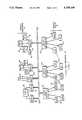
- FIG. 1is a general block diagram of a local area network constructed in accordance with this invention
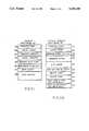
- FIG. 2Ais a diagram illustrating the contents of a service advertising message transmitted by the service providers in the network depicted in FIG. 1, and FIG. 2B is a diagram of a data base established by the service users in the network of FIG. 1 in response to the service advertising message depicted in FIG. 2A;
- FIG. 3Ais a diagram depicting a virtual circuit and service sessions, that is useful in understanding the operations of the network depicted in FIG. 1;
- FIGS. 3B and 3Care diagrams depicting databases used by the service providers and service users in the network depicted in FIG. 1;
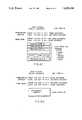
- FIG. 4is a state diagram useful in understanding the operation of the virtual circuit depicted in FIG. 3A;
- FIG. 5is a state diagram useful in understanding the operation of the service sessions depicted in FIG. 1;
- FIGS. 6A through 6Ddepict various formats of virtual circuit messages transmitted through the virtual circuit depicted in FIG. 3A;
- FIGS. 7A through 7Ddepict various formats of session slot messages transmitted between corresponding sessions in the device servers and nodes as depicted in FIG. 3A;
- FIG. 8depicts the timings of messages transmitted through the virtual circuits as depicted in FIG. 3A.
- FIG. 1illustrates a local area network 10 in which a plurality of service users, generally indicated by reference numeral 12, communicate with a plurality of service providers, generally indicated by reference numeral 14, over a common communications link 16.
- a communications link 16may take the form of any one of a number of communications lines and interface circuitry which transfer data between the service users and service providers in bit serial or parallel form.
- the communications linkmay take the form of a coaxial cable and interface circuitry which transmits messages using the well-known Ethernet local area network protocol. In that protocol, data is organized into messages having a predetermined format and transmitted in bit serial form between stations over the coaxial cable.
- the service users 12may include a plurality of devices such as, for example, video display terminals 18, printers 20, and personal computers 22.
- Network 10also includes a plurality of device servers 24 each of which may connect to several service users and enable the service users to communicate over communications link 16 with the service providers 14.
- the service providers 14may include devices such as processors 26, disk drives 28, tape storage units 30 and data links 32 (such as telephone lines or microwave links) and analog-to-digital converters 33.
- Network 10also includes a plurality of nodes 34, each of which may be connected to several service providers. Furthermore, each node 34 connects directly to communications link 16 and provides communications between the service providers connected to it and the communications link. It will be appreciated that in some cases a service provider and node may be integrated into one unit that performs both functions.
- the service providers 14provide service to the service users 12.
- Such servicesmay include, for example, electronic mail storage and forwarding among service users, word processing capabilities, access to programs such as payroll accounting, inventory control or the like, the ability to store or retrieve records on or from disk and tape files, the ability to communicate over telephone lines and microwave links, and the ability to acquire data from, for example, scientific instruments through analog-to-digital converters 33.
- Such services, as well as additional services,are well known in the art and will not be discussed further herein.
- service usersmay also provide services.
- certain personal computers 22 in network 10in addition to being a service user, may also have programs that may be accessed and used by another user, such as a terminal 18.
- the personal computermay be connected to a node 34 as well as to a device server 24 to make its programs available to a service user as services.
- a unit which interfaces the personal computer to the communications linkmay provide the facilities of both a node and a device server.
- each node 34transmits an "advertising" message which is received by all of the device servers 24, which identifies itself and the services provided by the service providers 14 connected to that node, as well as a "rating" for each service.
- the service advertising messageincludes a plurality of fields including a header 50, the contents of which depends on the protocol used over a communications line 16, and a body 54.
- the header 50has a node identification field 51 which identifies the transmitting node, a protocol type field 52 identifying the message as the service advertising message, and a multi-cast address field 53 which enables all of the device servers 24 to receive the message.
- the nodetransmits the body 54 of the message which identifies the various services provided by it and the rating for each service.
- the ratingsindicate, for example, how prompt the service provider 14 may be in responding to a service request, based in part on the number of service users 12 then using the service provided by the specific provider and, thus, the potential delay in responding to communications from another service user who might request the service.
- each device server 24(FIG. 1) establishes a service directory such as depicted in FIG. 2B.
- the directorycomprises a table in which the node identifications, the services provided by the nodes, and the service ratings are stored.
- the device servercan use the contents of the service directory depicted in FIG. 2B to determine which nodes provide that service. If more than one node provides the service requested, the device server uses the rating in the rating fields to determine which node has the highest rating for the service and requests that node to provide the service.
- the diverse services that are available from the service providersmay be divided into groups or classes and each user may be able to access only those services that are of interest to him.
- the service namesmay be organized into groups identified by group names, and the device server will display only those services to a particular user which are in the groups which the user can access.
- the device server 24When a user 12 requires a service provided by a service provider 14 identified in the service directory, the device server 24 begins to establish a virtual circuit 58 between itself and the node 34 that provides the service with the most desirable service rating. With reference to FIG. 3A, the device server 24 in a conventional manner establishes a virtual circuit state machine 60 which provides two-way data communications over a pair of unidirectional data pipes with a virtual circuit state machine 64 established by node 34.
- the virtual circuit state machines 60 and 64 and the data pipes 62provide a means for transferring data, in the form of messages between the device server 24 and the node 34 over the communications link 16. It will be appreciated that message communications through a number of data pipes 62 may be multiplexed over the communications link 16, and, accordingly, the communications link provides message communications for a number of virtual circuits in network 10.
- the virtual circuit state machine 60 at the device server 24communicates with the individual service users 12 by means of service sessions using separate session state machines 66 which the device server establishes in a conventional manner for each user.
- the node's virtual state machine 64communicates with the service providers 14 using separate session state machines 68.
- the device server 24 and node 34use messages transmitted over communication link 16 to set up the virtual circuit and the session state machines, which will be described below in connection with FIGS. 4 through 7D.
- the device server 24first determines whether a virtual circuit exists between it and the node 34 selected by the device server. If no such virtual circuit exists, the device server 24 transmits a virtual circuit message over communications link 16 to node 34 which causes the node to establish its virtual circuit state machine 64 to support its end of the virtual circuit 58.
- a session state machine 66is also set up between its virtual circuit state machine 60 and the user 12 to allow data and other information to be accumulated from and transferred to the user.
- a session slotis transmitted by device server 24 to node 34 through the virtual circuit 58, specifically over the communications link 16, identifying the required service, and the node 34 sets up a session state machine 68, which connects to the service provider which provides the required service and allows data and other information to be transferred between the virtual circuit state machine and the service provider.
- Each session state machinecollects information to be transferred from its connected user or service provider and provides the information in the form of session messages to the virtual circuit state machine.
- the virtual circuit state machineaccumulates the session messages from various service users' or providers' state machines which are to be transferred between the same device server 24 and node 34 and forms a single virtual circuit message for transfer through the virtual circuit 58 over the communications link 16.
- the receiving virtual circuit state machineOn receiving a virtual circuit message from the virtual circuit 58, the receiving virtual circuit state machine transfers the session messages to the respective session state machines that are the intended recipients for transfer to the respective service users 12 and service providers 14, and returns a single acknowledgement message over the virtual circuit to verify receipt of the virtual circuit message. It will be appreciated that requiring only a single virtual circuit acknowledgement message for the multiplexed messages between service users and providers reduces the acknowledgement message traffic from that often required in the prior art, thereby reducing the traffic overhead over communications link 16, and also reduces the overhead required at the device server and node to generate the acknowledgement messages.
- the virtual circuit state machines 60 and 64 in device server 24 and node 34, respectively,include a data base as depicted in FIG. 3B used in transmitting and receiving messages through pipes 62.
- Data base 70includes a remote identification word 72 and a local identification word 74.
- the identification words 72 and 74contain the identification of the virtual circuit 58 as assigned by node 34 and device server 24.
- the contents of the local identification word 74are assigned by the unit in which the data base 70 resides, and the contents of the remote identification word 72 are assigned by the other unit engaged in the virtual circuit.
- the local identification wordis assigned by the device server and the remote identification word is assigned by the node 34 which provides the other end of the virtual circuit.
- the contents of the local identification word 74are assigned by the node, and the contents of the remote identification word 72 is assigned by the device server.
- the contents of the two identification words 72 and 74are transmitted in the virtual circuit messages transferred through the virtual circuit over communications link to allow the device server and node to identify the messages transferred over communications link 16 as being associated with the particular virtual circuit.
- the virtual circuit data base 70also includes a message type field 76 which identifies the type of virtual circuit message to be transmitted next.
- a message type field 76which identifies the type of virtual circuit message to be transmitted next.
- Three types of virtual circuit messagesare transmitted over a virtual circuit, namely, a START virtual circuit message, a RUN message, and a STOP virtual circuit message, which are detailed below in connection with FIGS. 4 and 6A through 6D.
- An M field 78identifies whether the unit including the data base 70 is a master or slave unit.
- device servers 24are always masters and nodes 34 are always slaves; communications over a virtual circuit are always initiated by the device servers and the nodes always acknowledge or respond to the communications from the device servers.
- An R field 80when set, indicates that the last sent message requires a response.
- Data base 70also includes message counters 82 and acknowledgement counters 84.
- Each message transmitted by device server 24 or node 34includes a message sequence number that is checked by the virtual circuit state machine in the receiving unit to ensure that the successive messages are properly received in sequence. Messages are re-transmitted to ensure that they are properly received if they are not acknowledged within a predetermined time; the sequence numbers ensure that the receiving device does not treat a re-transmitted message as a new message if it, in fact, correctly received the message on a previous transmission.
- the contents of the message counters 82identify the number of messages which have been transmitted and received, and the acknowledgement counters contain the message numbers of the messages which have been acknowledged. Thus, if a message number is skipped, or if acknowledgements are not received in numerical order, the device server and node can determine which messages may have not been properly transmitted over communications link 16.
- a data waiting flag (DWF) 86is set whenever any session state machine has data to send over the virtual circuit.
- the data waiting flagis set when a message is received from a node which requires a response.
- a retransmit counter 88 and retransmit timer 90are used in retransmitting messages which have not been acknowledged within a time selected by the retransmit timer.
- the transmitting unitretransmits each unacknowledged message a number of times as selected by the retransmit counter 88. If the message is not acknowledged after the retransmit counter counts out, the other end of the virtual circuit is marked out of service.
- the virtual circuit data base 70 in a device server 24also includes a server circuit timer 92.
- the device server 24transmits a message, it resets its server circuit timer 92 and is thereafter inhibited from transmitting a subsequent message until the server circuit timer times out.
- the device serveris inhibited from transmitting virtual circuit messages over virtual circuit 58 until the server circuit timer times out.
- the server circuit timer 92has timed out, the device server 24 does not transmit any messages unless the data waiting flag 86 is set.
- the device server 24may then immediately transmit a new virtual circuit message over the virtual circuit 58. If a previously transmitted message has not been acknowledged, a device server or node waits an amount of time as specified by the retransmit timer 90 and then retransmits the unacknowledged message.
- the server circuit timer 92thus ensures at least a minimum delay period between the transmission of new virtual circuit messages by the device server 24 through any particular virtual circuit.
- message transmissionswill be based on the timing out of the server circuit timer 92.
- the virtual circuit message transmissionwill be based on the setting of the data waiting flag 86. Since, with one exception as explained below, the nodes 34 only respond to or otherwise acknowledge virtual circuit messages from the device servers, the server circuit timers and the data waiting flags in the device servers also govern message traffic from the nodes through the virtual circuits.
- the network 10(FIG.
- the virtual circuit data base 70 in a device server 24also includes a keep-alive timer 94 which enables the device server to send a message over the virtual circuit if it has not sent any messages thereover for a very long period of time, to ensure that the node 34 maintains support for its end of the virtual circuit.
- the node 34responds, thereby informing the device server that it also has not gone down.
- the service user and service provider providing the service required by the usercommunicate by means of session slots. More specifically, the session state machines at the device server and node transfer session slots which cause transitions between states in the respective session state machines and also transfer service data and status information between the service user and provider.
- Each session state machineuses a session data base 100 depicted in FIG. 3C.
- the session data baseincludes a remote identification field 102 and a local identification field 104, which are used in the same way as a virtual circuit state machine uses the remote and local identification fields 72 and 74 in the virtual circuit data base 70(FIG. 3B).
- each virtual circuit message that is transmitted over a virtual circuitmay include session slots for different service sessions (that is, session slots intended to be used by different session state machines in the device servers and nodes that communicate over the same virtual circuit) and the remote and local identification fields 102 and 104 identify the session and session state machines that are the intended recipients of the session slots.
- the contents of local identification fieldare assigned by the unit in which the data base resides, and the contents of the remote data base are assigned by the other unit.
- Each session data base 100also includes a data buffer 106 for storing data received from or to be transmitted to the service user 12 or service providers 14 associated with the particular session state machine.
- a data ready flag 108is set, which in turn enables the data waiting flag 86 in the virtual circuit data base 70 to be set.
- the device server or nodethereafter sends a message virtual circuit, it can poll the data ready flags of the service sessions assigned to the virtual circuit to determine whether their data buffers have data to transmit, and may remove the contents of various fields, including the data from the data buffers 106 whose associated data ready flags as set, to generate session slots for transfer in a virtual circuit message.
- a byte count field 110identifies the number of bytes of data in the data buffer 106 and is sent with the data in the session slot.
- a session slot type field 112identifies the type of session slot to be sent.
- Five types of session messagescan be sent, including START, STOP, REJECT, DATA, and STATUS messages. -The contents of the session messages will be described below in connection with FIGS. 5 and 7A through 7D.
- Local and remote credits fields 114 and 116 in the session data base 100relate to the number of slots that are available, with each slot relating to a specific amount of data.
- Each session slot transmitted over a virtual circuitincludes a credits field which identifies the amount of space available in the data buffer for any response information from the unit at the other end of the virtual circuit engaged in the service session.
- the contents of the credits field in the messageis provided by the contents of the local credits field 114 in the session data base 100 of the unit transmitting the message.
- the contents of the remote credits field 116is provided by the contents of the credits portion of the session slot received from the unit at the other end of the virtual circuit.
- FIG. 4illustrates the various states of virtual circuit state machines 60 and 64 (FIG. 3A) and the various messages which can be transmitted over the virtual circuit during those states and which cause transitions among states.
- FIGS. 6A through 6Ddetail the contents of the various virtual circuit messages.
- three types of virtual circuit messagesare transmitted through the virtual circuit, including a START virtual circuit message, a STOP virtual circuit message, and a RUN message.
- the START and STOP virtual circuit messagesare used to establish and abolish the virtual circuit, and the RUN message is used to transfer information, including session slots, between service users and providers.
- the state machines 60 and 64 in the device server 24 and node 34respectively are both initially in a HALTED state.
- the device server 24transmits a START virtual circuit message to node 34.
- FIG. 6Adepicts the general format of a virtual circuit message.
- the messagebegins with a communications link header 120, the format of which depends on the particular communications link 16 selected for the network 10.
- the communications link headerincludes a destination address field 122 and a source address field 124 which identify the particular sending and receiving node and device server, and a protocol type 126.
- the messageAfter the communications link header 120, the message includes a virtual circuit header 130 which identifies the virtual circuit over which the message is being transmitted.
- the virtual circuit headerincludes a destination virtual circuit identification field 132 and a source virtual circuit identification field 134 the contents of which are provided by the remote and local identification fields 72 and 74 in data base 70 (FIG. 3B). These fields 132 and 134 identify the virtual circuit through which the message is being transmitted. Since each receiving unit may have several virtual circuits, even between itself and the same node or device server, the fields 132 and 134 are used to identify the specific virtual circuit for which the message received over communications link 16 is intended. If the message is a START virtual circuit message from device server 24, with reference to FIG. 6B, the destination virtual circuit identification field 132 contains a "0", and the source virtual circuit identification field contains an identification that is assigned by the device server 24.
- the virtual circuit header 130also includes a message type field, an M flag and an R flag, the contents of which are provided by fields 76, 78, and 80 in the virtual circuit data base 70 (FIG. 3B).
- the header 30also includes message sequence and acknowledgement sequence numbers taken from counters 82 and 84, and a field 136 which identifies the number of session slots that may be included in a data field 140.
- the contents of session number field 136is used only in connection with a RUN virtual circuit message (FIG. 6C) described below.
- the data field 140contains information used by the recipient in setting up the virtual circuit
- a STOP virtual circuit message(FIG. 6D) the data field contains information as to the reason the virtual circuit is being stopped.
- a virtual circuit message(FIG. 6A) ends in an error check field 142 which contains a cyclic redundancy check word used to verify that the message was received without errors.
- the device server 24transmits the START virtual circuit message, it shifts from a HALTED state to a STARTING state.
- the node 34receives the START virtual circuit message, it shifts from a HALTED state to a STARTING state and responds with either a START virtual circuit message, indicating that it will support and participate in the virtual circuit, or a STOP virtual circuit message, indicating that it will not support the virtual circuit.
- the node 34retrieves the contents of the source virtual circuit identification field 134 from the message and stores it in the remote identification field 72 in its virtual circuit data base 70 as the device server's identification of the virtual circuit.
- the nodeuses the contents of the source virtual circuit identification field 134 from the device server's START virtual circuit message as the contents of the destination virtual circuit field 132 in its responding START virtual circuit message.
- the nodealso provides the contents of the source virtual circuit identification field 134 (FIG. 6A) as its identification code for the virtual circuit.
- the device serverretrieves the contents of this field, stores it in the remote identification field in its data base 70 for this virtual circuit and thereafter uses it in the destination virtual circuit identification field 132 of future messages transmitted over the virtual circuit.
- the noderesponds with a STOP virtual circuit message, it also provides a source virtual circuit identification code and the data field 140 identifies the reason that the node will not support the virtual circuit; one such reason may be that the node 34 is currently supporting other virtual circuits and has insufficient resources to provide support for another virtual circuit. If the node 34 transmits a STOP virtual circuit message to the device server, both the node and the device server return to the halted state. The device server may then attempt to establish a virtual circuit to another node connected to a service provider that provides the desired service or inform the user that the service is not available if no other node provides the service.
- the usermay determine, after the device server has transmitted a START virtual circuit message, that it does not need to use the particular service. This is indicated in FIG. 4 by a USER HALT directed at the STARTING state of device server 24. If that occurs, the device server transmits a STOP virtual circuit message (FIGS. 6A and 6D) to node 34. Both virtual circuit state machines 60 and 64 then return to the halted condition.
- both the state machines 60 and 64shift to a RUNNING state.
- the device server 24 and node 34can transmit RUN virtual circuit messages depicted in FIGS. 6A and 6C.
- the data field 140contains session slots which are described below (FIGS. 5 and 7A through 7D).
- the number of session messagesis identified in the session number field 136 in the virtual circuit header 130 (FIG. 6A).
- the device server 24 and node 34transmit service information between the service users 12 and service providers 14 (FIG. 1), more specifically the service information is transmitted between service state machines 66 and 68.
- the device servermay transmit a STOP virtual circuit message (FIGS. 6A and 6D) to node 34 and return to the HALTED state.
- the device server 24 and node 34can transmit RUN virtual circuit messages which include session slots.
- the session state machines 66 and 68are established, and service data and status information are transmitted between the service user and provider.
- the session state machinesmay then be abolished, thereby terminating the service session.
- the session slotswhich are depicted in FIGS. 7A through 7D. By means of the session slots, the session state machines 66 and 68 shift among various states as depicted in FIG. 5.
- the session state machine 66 of device server 24has five states, including a HALTED state, a STARTING state, an ABORT START state, a RUNNING state, and a STOPPING state.
- the session state machine 68 of node 34has four states, including a HALTED state, a STARTING state, a RUNNING state, and a STOPPING state. Initially, both state machines 66 and 68 are in a halted state, and when a user requests a particular service, the device server transmits a START session message, in a virtual circuit message through the virtual circuit.
- the format of a session messageincludes a session header 150 which includes destination session identification field 152, a source session identification field 154, a byte count field 156, a session slot type field 158, and a credits field 160.
- a session data field 162carries information for establishing and abolishing a session, as well as service session data and status information.
- the destination and source session identification fields 152 and 154are used in the identical manner as the destination and source virtual circuit identification fields 122 and 124 (FIG. 6A) described above. The contents of these fields are stored in and taken from the remote and local identification fields 102 and 104 in the session data base 100 (FIG. 3C).
- the contents of the byte count field 156identify the length of the session data field 162, and are taken from the byte count field 110 in the data base 100.
- the contents of the session slot type fieldare taken from field 112 in the session data base, and identify the type of message being transmitted. As noted above, five types of session slots may be,. transmitted.
- the contents of the CREDITS field 160are taken from the local credits field 114 in session data base 100 (FIG. 3C) to identify the number of slots that are available in the data buffer 106 for any response. When a unit receives a session slot, the contents of the CREDITS field may be stored in the remote credits field 116 of the session database 100 to indicate the amount of space in the data buffer 106 available for a subsequent session slot transfer.
- the session data field 162provides information required by the session state machine at node 34 for setting up the session. Such information may include, for example, the type of service required, thereby identifying the service provider which is to engage in the service session, and size of the data buffer 106 set aside for the session in the device server.
- the session state machine 66shifts to a STARTING state.
- the node's session state machine 68shifts to the STARTING state and the node responds with either a START session slot, after which the state machine 68 shifts to the RUNNING state, or a REJECT session slot (FIG. 7D), after which the state machine shifts to the HALTED state.
- the node 34supplies its session identification code in the source session identification field 154 (FIG. 7A). If the node responds with a REJECT session slot, the credits field 160 also contains the reason that it is rejecting the service session. Such reasons may include, for example, that the node is unable to provide the service because of inadequate resources, or that the node or the service provider is shutting down.
- the device server 24may receive the START session or REJECT session slot from node 34 when it is in either the STARTING state or in an ABORT START state.
- the device server's session state machine 66shifts from the STARTING state to the ABORT START stage if a user disconnect request, indicating that the user does not want to use the service which it previously selected, is received from a user before either a START session or a REJECT session slot is received from node 34 . If the session state machine 66 is in the ABORT START state, and if a REJECT session slot is received, the session state machine 66 merely returns to the HALTED state.
- the device server 24transmits a STOP session slot over the virtual circuit to the node causing its session state machine 68 to return to the HALTED state. In either case, both session state machines 66 and 68 return to the HALTED state.
- the device server's session state machine 66is in the STARTING state, and if the device server receives a START message from the node 34, its session state machine shifts to the RUNNING state. In that state, and with the node's session state machine 68 in the RUNNING state, RUN session slots including service data and status information may be transmitted back and forth between device server 24 and node 34 over the virtual circuit.
- the session data field 162 in such messagescontains user and service provider data and status information.
- FIG. 8depicts the timings of various messages transmitted between a device server 24 and node 34, in response to the service circuit timer 92 and the R flag 80, the R flag in the server being set or cleared by the R field in a virtual circuit header in a message from the node.
- FIG. 8also illustrates the timings of the retransmissions of various messages that are not received by the server and node, in response to the re-transmit timers 90 in each unit. Specifically, when a node receives a message from the device server, it will respond with a message having the R field being either set or clear depending on whether or not the message includes data.
- the R fieldis clear, and the node may thereafter transmit a second message to the device server which includes data.
- the second messagehas a set R field. This is illustrated in time (E).
- the second messagemay cross with another message from the device server, which may transmit a message when its data waiting flag is set, when its service circuit timer times out.
- the R field being setforces the data waiting flag to be set, thereby enabling the server to send an acknowledging message to the node, whether or not it actually has data to send.
- the R field being clearenables the node to thereafter send another message with data, thereby removing the constraint on the node that it send messages, and therefore data, only when it receives messages from the server.
- each node 34 connected into network 10transmits a multicast service advertising message (FIG. 2A) identifying the particular services which are available through it. All of the device servers receive the advertising message and establish a service directory (FIG. 2B) identifying the services which are available and the nodes and ratings of the services available through each node. The available services may be displayed to the operators of the service users from the device servers' directories.
- a multicast service advertising message(FIG. 2A) identifying the particular services which are available through it.
- All of the device serversreceive the advertising message and establish a service directory (FIG. 2B) identifying the services which are available and the nodes and ratings of the services available through each node.
- the available servicesmay be displayed to the operators of the service users from the device servers' directories.
- a service user 12When a service user 12 requires the use of a service, its device server 24 determines which node 34 provides the service and which has the highest service rating for that service. The device server 24 then determines whether it has a virtual circuit 58 between itself and that node. If no such virtual circuit exists, the device server transmits a START virtual circuit message (FIGS. 6A and 6B) to the node to attempt to establish a virtual circuit over communications link 16. If the node responds with a START virtual circuit message, the virtual circuit has been established and the device server 24 then establishes a session between the virtual circuit 58 and the user 12 requesting the service.
- START virtual circuit messageFIGS. 6A and 6B
- the device serverneed not set up another virtual circuit, but instead may proceed to the next steps and use the existing virtual circuit for communications.
- some communications linkssuch as a link conforming to the Ethernet protocol, it may be desirable to limit the number of users using a single virtual circuit, since the length of each virtual circuit message is limited. Accordingly, even if a virtual circuit is already established between the device server and node, it may be desirable to establish additional virtual circuits if a maximum number of users are already using one virtual circuit.
- the device server 24may transmit virtual circuit messages through the virtual circuit including session messages multiplexed from several service sessions.
- a sessionbegins with a START session slot (FIGS. 7A and 7B) transmitted to device server 24 to node 34 identifying the required service, in an attempt to establish a service session over the virtual circuit 58 with the service provider 14 which provides the required service. If the service session is established, service data and status information can be transmitted in RUN session messages.
- the rate at which the device server can transmit virtual circuit messages over the communications link 16is limited by the server circuit timer 92 (FIG. 3B) thereby allowing messages for other virtual circuits to be multiplexed over the communications link. Furthermore, the data waiting flags 86 in the device server and node exhibits it from transmitting virtual circuit messages through the virtual circuit until it has information to transmit. Thus, the device server does not transmit any messages over the virtual circuit 58 unless it has information available to be transmitted or unless it has received a message from the node in which the response requested flag has been set, and then no more often than permitted by the server circuit timer.
- the sessioncan be abolished by device server transmitting a STOP session slot. If all of the sessions are abolished for a virtual circuit, the device server 24 may then abolish the virtual circuit by the transmission of a STOP virtual circuit message.
- a single virtual circuit message transmitted over the virtual circuit 58can contain messages between a number of users 12 and service providers 14.
- the number of acknowledgement messagesmay be reduced to one response message for each virtual circuit message. This reduction results in, not only a reduced amount of message traffic over the communications link since only the virtual circuit messages between nodes and device servers are acknowledged, and not the messages between particular service users and service providers.
- each message between service users and service providershad been acknowledged by a separate acknowledgement message, which not only increased message traffic over the communications link, but also required processing activities by the service user and service provider that are not required in the network 10 constructed in accordance with the invention.
Landscapes
- Engineering & Computer Science (AREA)
- Computer Security & Cryptography (AREA)
- Computer Hardware Design (AREA)
- Computer Networks & Wireless Communication (AREA)
- Signal Processing (AREA)
- Physics & Mathematics (AREA)
- General Engineering & Computer Science (AREA)
- Theoretical Computer Science (AREA)
- Mathematical Physics (AREA)
- Software Systems (AREA)
- General Physics & Mathematics (AREA)
- Computer And Data Communications (AREA)
Abstract
Description
Claims (32)
Priority Applications (3)
| Application Number | Priority Date | Filing Date | Title |
|---|---|---|---|
| US07/412,576US5058108A (en) | 1984-06-01 | 1989-09-25 | Local area network for digital data processing system |
| US08/223,245US5734659A (en) | 1984-06-01 | 1994-04-01 | Computer network having a virtual circuit message carrying a plurality of session messages |
| US08/225,365US5621734A (en) | 1984-06-01 | 1994-04-08 | Local area network with server and virtual circuits |
Applications Claiming Priority (3)
| Application Number | Priority Date | Filing Date | Title |
|---|---|---|---|
| US61655384A | 1984-06-01 | 1984-06-01 | |
| US33848589A | 1989-04-13 | 1989-04-13 | |
| US07/412,576US5058108A (en) | 1984-06-01 | 1989-09-25 | Local area network for digital data processing system |
Related Parent Applications (1)
| Application Number | Title | Priority Date | Filing Date |
|---|---|---|---|
| US33848589AContinuation | 1984-06-01 | 1989-04-13 |
Related Child Applications (1)
| Application Number | Title | Priority Date | Filing Date |
|---|---|---|---|
| US72406491ADivision | 1984-06-01 | 1991-07-01 |
Publications (1)
| Publication Number | Publication Date |
|---|---|
| US5058108Atrue US5058108A (en) | 1991-10-15 |
Family
ID=27407276
Family Applications (1)
| Application Number | Title | Priority Date | Filing Date |
|---|---|---|---|
| US07/412,576Expired - LifetimeUS5058108A (en) | 1984-06-01 | 1989-09-25 | Local area network for digital data processing system |
Country Status (1)
| Country | Link |
|---|---|
| US (1) | US5058108A (en) |
Cited By (47)
| Publication number | Priority date | Publication date | Assignee | Title |
|---|---|---|---|---|
| US5341505A (en)* | 1990-10-30 | 1994-08-23 | Whitehouse Harry T | System and method for accessing remotely located ZIP+4 zipcode database |
| US5390169A (en)* | 1993-06-11 | 1995-02-14 | At&T Corp. | Routing to intelligence |
| US5392277A (en)* | 1993-06-11 | 1995-02-21 | At&T Corp. | Routing to intelligence |
| US5421024A (en)* | 1991-04-30 | 1995-05-30 | Hewlett-Packard Company | Detection of a relative location of a network device using a multicast packet processed only by hubs |
| US5446868A (en)* | 1992-09-11 | 1995-08-29 | R. J. Reynolds Tobacco Company | Network bridge method and apparatus |
| US5528605A (en)* | 1991-10-29 | 1996-06-18 | Digital Equipment Corporation | Delayed acknowledgement in an asymmetric timer based LAN communications protocol |
| US5546379A (en)* | 1993-10-01 | 1996-08-13 | Nec America | Bandwidth-on-demand remote office network apparatus and method |
| US5557798A (en)* | 1989-07-27 | 1996-09-17 | Tibco, Inc. | Apparatus and method for providing decoupling of data exchange details for providing high performance communication between software processes |
| US5638517A (en)* | 1992-08-14 | 1997-06-10 | International Business Machines Corp. | Method and apparatus for transmitting a message from a computer system over a network adapter to the network by performing format conversion and memory verification |
| US5640513A (en)* | 1993-01-22 | 1997-06-17 | International Business Machines Corporation | Notification of disconnected service machines that have stopped running |
| US5652908A (en)* | 1991-10-02 | 1997-07-29 | International Business Machines Corporation | Method and apparatus for establishing communications sessions in a remote resource control environment |
| US5706439A (en)* | 1994-09-27 | 1998-01-06 | International Business Machines Corporation | Method and system for matching packet size for efficient transmission over a serial bus |
| US5740549A (en)* | 1995-06-12 | 1998-04-14 | Pointcast, Inc. | Information and advertising distribution system and method |
| US5870386A (en)* | 1991-01-09 | 1999-02-09 | Digital Equipment Corporation | Method and apparatus for transparently bridging traffic across wide area networks |
| US5870605A (en)* | 1996-01-18 | 1999-02-09 | Sun Microsystems, Inc. | Middleware for enterprise information distribution |
| US5873084A (en)* | 1996-01-18 | 1999-02-16 | Sun Microsystems, Inc. | Database network connectivity product |
| US5893911A (en)* | 1996-04-17 | 1999-04-13 | Neon Software, Inc. | Method for defining and applying rules for message distribution for transaction processing in a distributed application |
| US5903562A (en)* | 1996-12-13 | 1999-05-11 | Hewlett-Packard Company | Multicasting employing publication title to create numeric destination address for computer network system frame |
| US5916307A (en)* | 1996-06-05 | 1999-06-29 | New Era Of Networks, Inc. | Method and structure for balanced queue communication between nodes in a distributed computing application |
| US6138162A (en)* | 1997-02-11 | 2000-10-24 | Pointcast, Inc. | Method and apparatus for configuring a client to redirect requests to a caching proxy server based on a category ID with the request |
| US6147987A (en)* | 1997-04-08 | 2000-11-14 | 3Com Corporation | Supporting load sharing across multiple network access servers |
| US6173311B1 (en) | 1997-02-13 | 2001-01-09 | Pointcast, Inc. | Apparatus, method and article of manufacture for servicing client requests on a network |
| WO2001028161A1 (en)* | 1999-10-08 | 2001-04-19 | Microsoft Corporation | Fair scheduling in broadcast environments |
| US6233232B1 (en)* | 1997-04-08 | 2001-05-15 | 3Com Corporation | Supporting multilink connections across multiple network access servers |
| US6243751B1 (en)* | 1997-06-11 | 2001-06-05 | Oracle Corporation | Method and apparatus for coupling clients to servers |
| US6298458B1 (en)* | 1999-01-04 | 2001-10-02 | International Business Machines Corporation | System and method for manufacturing test of a physical layer transceiver |
| US20010056475A1 (en)* | 1995-12-20 | 2001-12-27 | Anderson William P. | System for on-line financial services using distributed objects |
| US6477670B1 (en)* | 1999-01-29 | 2002-11-05 | Nortel Networks Limited | Data link layer quality of service for UMTS |
| US20020178026A1 (en)* | 2000-05-22 | 2002-11-28 | Robertson James A. | Method and system for implementing a global lookup in a global ecosystem of interrelated services |
| US20020194112A1 (en)* | 2000-11-17 | 2002-12-19 | Depinto Robert | System and method for exchanging creative content |
| US20040059722A1 (en)* | 2002-09-24 | 2004-03-25 | Yeh Danny Lo-Tien | Method and apparatus for discovery of dynamic network services |
| US6712702B2 (en) | 1996-01-19 | 2004-03-30 | Sheldon F. Goldberg | Method and system for playing games on a network |
| US20040158524A1 (en)* | 1995-10-11 | 2004-08-12 | Block Financial Corporation | Financial information access system |
| US6807558B1 (en) | 1995-06-12 | 2004-10-19 | Pointcast, Inc. | Utilization of information “push” technology |
| US20060195629A1 (en)* | 2005-02-28 | 2006-08-31 | Freescale Semiconductor Inc. | Method of repeating data transmission between network devices |
| US7127526B1 (en)* | 2000-03-20 | 2006-10-24 | Nortel Networks Limited | Method and apparatus for dynamically loading and managing software services on a network device |
| US7360159B2 (en) | 1999-07-16 | 2008-04-15 | Qarbon.Com, Inc. | System for creating media presentations of computer software application programs |
| US20090037995A1 (en)* | 2007-07-31 | 2009-02-05 | Onesimo Zapata | System and Method For Authentication Of Users In A Secure Computer System |
| US7496943B1 (en) | 1996-01-19 | 2009-02-24 | Beneficial Innovations, Inc. | Network system for presenting advertising |
| US8050969B2 (en) | 1995-07-25 | 2011-11-01 | News America Marketing Properties Llc | Interactive marketing network and process using electronic certificates |
| US20130122805A1 (en)* | 2011-11-16 | 2013-05-16 | Canon Kabushiki Kaisha | Communication apparatus and control method thereof |
| US8775245B2 (en) | 2010-02-11 | 2014-07-08 | News America Marketing Properties, Llc | Secure coupon distribution |
| US8892495B2 (en) | 1991-12-23 | 2014-11-18 | Blanding Hovenweep, Llc | Adaptive pattern recognition based controller apparatus and method and human-interface therefore |
| US9530150B2 (en) | 1996-01-19 | 2016-12-27 | Adcension, Llc | Compensation model for network services |
| US9535563B2 (en) | 1999-02-01 | 2017-01-03 | Blanding Hovenweep, Llc | Internet appliance system and method |
| US20180295192A1 (en)* | 2016-05-31 | 2018-10-11 | Brocade Communications Systems LLC | Keep-alive technique in a network device |
| EP4468762A1 (en) | 2023-05-25 | 2024-11-27 | Giesecke+Devrient Mobile Security Germany GmbH | A communication system and method for enabling inactivity timeout based on terminal timer |
Citations (17)
| Publication number | Priority date | Publication date | Assignee | Title |
|---|---|---|---|---|
| US4039737A (en)* | 1976-02-13 | 1977-08-02 | Kemper Eugene L | Electric immersion heating apparatus and methods of constructing and utilizing same |
| US4063220A (en)* | 1975-03-31 | 1977-12-13 | Xerox Corporation | Multipoint data communication system with collision detection |
| US4199663A (en)* | 1978-11-06 | 1980-04-22 | The Boeing Company | Autonomous terminal data communications system |
| US4227178A (en)* | 1977-10-18 | 1980-10-07 | International Business Machines Corporation | Decentralized data transmission system |
| US4236245A (en)* | 1979-04-17 | 1980-11-25 | Bell Telephone Laboratories, Incorporated | Ring communication system data packets reusable a variable number of times |
| US4241398A (en)* | 1978-09-29 | 1980-12-23 | United Technologies Corporation | Computer network, line protocol system |
| US4292623A (en)* | 1979-06-29 | 1981-09-29 | International Business Machines Corporation | Port logic for a communication bus system |
| US4320502A (en)* | 1978-02-22 | 1982-03-16 | International Business Machines Corp. | Distributed priority resolution system |
| US4332027A (en)* | 1981-10-01 | 1982-05-25 | Burroughs Corporation | Local area contention network data communication system |
| US4379294A (en)* | 1981-02-12 | 1983-04-05 | Electric Power Research Institute, Inc. | Data highway access control system |
| US4385382A (en)* | 1980-09-29 | 1983-05-24 | Honeywell Information Systems Inc. | Communication multiplexer having a variable priority scheme using a read only memory |
| EP0081056A2 (en)* | 1981-11-27 | 1983-06-15 | International Business Machines Corporation | A data processing network having a distributed data file access control |
| US4410889A (en)* | 1981-08-27 | 1983-10-18 | Burroughs Corporation | System and method for synchronizing variable-length messages in a local area network data communication system |
| EP0160263A2 (en)* | 1984-05-03 | 1985-11-06 | International Business Machines Corporation | Distributed control of alias name usage in networks |
| US4592048A (en)* | 1984-05-03 | 1986-05-27 | At&T Bell Laboratories | Integrated packet switching and circuit switching system |
| US4596010A (en)* | 1984-05-03 | 1986-06-17 | At&T Bell Laboratories | Distributed packet switching arrangement |
| US4663756A (en)* | 1985-08-29 | 1987-05-05 | Sperry Corporation | Multiple-use priority network |
- 1989
- 1989-09-25USUS07/412,576patent/US5058108A/ennot_activeExpired - Lifetime
Patent Citations (17)
| Publication number | Priority date | Publication date | Assignee | Title |
|---|---|---|---|---|
| US4063220A (en)* | 1975-03-31 | 1977-12-13 | Xerox Corporation | Multipoint data communication system with collision detection |
| US4039737A (en)* | 1976-02-13 | 1977-08-02 | Kemper Eugene L | Electric immersion heating apparatus and methods of constructing and utilizing same |
| US4227178A (en)* | 1977-10-18 | 1980-10-07 | International Business Machines Corporation | Decentralized data transmission system |
| US4320502A (en)* | 1978-02-22 | 1982-03-16 | International Business Machines Corp. | Distributed priority resolution system |
| US4241398A (en)* | 1978-09-29 | 1980-12-23 | United Technologies Corporation | Computer network, line protocol system |
| US4199663A (en)* | 1978-11-06 | 1980-04-22 | The Boeing Company | Autonomous terminal data communications system |
| US4236245A (en)* | 1979-04-17 | 1980-11-25 | Bell Telephone Laboratories, Incorporated | Ring communication system data packets reusable a variable number of times |
| US4292623A (en)* | 1979-06-29 | 1981-09-29 | International Business Machines Corporation | Port logic for a communication bus system |
| US4385382A (en)* | 1980-09-29 | 1983-05-24 | Honeywell Information Systems Inc. | Communication multiplexer having a variable priority scheme using a read only memory |
| US4379294A (en)* | 1981-02-12 | 1983-04-05 | Electric Power Research Institute, Inc. | Data highway access control system |
| US4410889A (en)* | 1981-08-27 | 1983-10-18 | Burroughs Corporation | System and method for synchronizing variable-length messages in a local area network data communication system |
| US4332027A (en)* | 1981-10-01 | 1982-05-25 | Burroughs Corporation | Local area contention network data communication system |
| EP0081056A2 (en)* | 1981-11-27 | 1983-06-15 | International Business Machines Corporation | A data processing network having a distributed data file access control |
| EP0160263A2 (en)* | 1984-05-03 | 1985-11-06 | International Business Machines Corporation | Distributed control of alias name usage in networks |
| US4592048A (en)* | 1984-05-03 | 1986-05-27 | At&T Bell Laboratories | Integrated packet switching and circuit switching system |
| US4596010A (en)* | 1984-05-03 | 1986-06-17 | At&T Bell Laboratories | Distributed packet switching arrangement |
| US4663756A (en)* | 1985-08-29 | 1987-05-05 | Sperry Corporation | Multiple-use priority network |
Non-Patent Citations (60)
| Title |
|---|
| "Proposal for Implementation and Evaluation of an Ethernet Terminal Front-End", Carnegie-Mellon University, 15 Jun. 1981. |
| 1. Field of the Invention |
| 2. Description of the Prior Art |
| Arnold, Net/One Performance Measurements, Ungermann Bass Inc. Dec. 16, 1981.* |
| Arnold, Net/One Performance Measurements, Ungermann-Bass Inc. Dec. 16, 1981. |
| As small and medium-sized computer systems are becoming less expensive and more powerful, a number of them are being interconnected to form networks to ensure that a number of different types of services are available at any time to users having diverse processing needs. Such services may include any of the services which are normally available from such networks, including such as electronic mail (mail storage and forwarding), word processing, accounting, such as payroll or inventory, or data communications over telephone lines or microwave links. Interconnecting systems into a network helps to enhance the availability of services to service users by including a number of service providers in the network and having each provider provide one or more of the services, thus reducing the likelihood that the failure of any one service provider in the network will result in a significant number of services being unavailable to the users at any one time. Indeed, a local network may be arrange |
| Bass et al., "Local Network Gives New Flexibility to Distributed Processing", Electronics, pp. 114-120 (Sep. 1980), reprinted in Freeman et al., Tutorial Microcomputer Networks, IEEE catalog number EH0190-9, pp. 214-222 (1981). |
| Bass et al., Local Network Gives New Flexibility to Distributed Processing , Electronics, pp. 114 120 (Sep. 1980), reprinted in Freeman et al., Tutorial Microcomputer Networks, IEEE catalog number EH0190 9, pp. 214 222 (1981).* |
| Carpenter et al., A Microprocessor Based Local Network Node, Proceedings COMPCON Fall 78, pp. 104 109 (Sep. 1978), copy from reprint in Freeman at pp. 148 153.* |
| CCITT, Data Communication Networks Services and Facilities, Terminal Equipment and Interfaces, Recommendation X.1 X.29, published 1981.* |
| CCITT, Data Communication Networks--Services and Facilities, Terminal Equipment and Interfaces, Recommendation X.1-X.29, published 1981. |
| Danthine, et al., "Transport Layer--Long-Haul vs Local Network," Local Networks for Computer Communications, pp. 271-296 (1981). |
| Danthine, et al., Transport Layer Long Haul vs Local Network, Local Networks for Computer Communications, pp. 271 296 (1981).* |
| Davidson, "Connection-Oriented Protocols of Net/One", Local Computer Networks, North Holland Publishing Company, pp. 319-333 1982. |
| Davidson, Connection Oriented Protocols of Net/One , Local Computer Networks, North Holland Publishing Company, pp. 319 333 1982.* |
| Hyde, "The Networked Plans of Mr. Lan", Electronic Business, pp. 88-100, Mar. 1, 1985. |
| Hyde, The Networked Plans of Mr. Lan , Electronic Business, pp. 88 100, Mar. 1, 1985.* |
| If the operator desires to use a service provided by a unit connected to a node, it may request connection to the node and, through the node, to the unit to have the service provided. Normally, the operator has to know the particular node(s) and unit(s) that provides the desired service. The operator selects a node and unit to provide the service, and causes the terminal server to request service by that node and service provider. The terminal server and the node exchange messages which enable a "virtual circuit" to be established which provides a data transfer mechanism between the operator's terminal and the provider of the service. Thevirtual circuit essentially extends from the operator's terminal, as the service user, through the terminal server, over the communications link and through the node to the service provider. If a number of users are using the local area network, severalvirtual circuits may be established over the communications link to provide communications between |
| In brief summary, the invention provides a local area network over which a plurality of users, such as terminals or printers, communicate with service providers, such as data processing systems, data storage devices such as disk or tape records, or data links such as telephone lines or microwave transmission links. One or more device servers connects directly to a communications link. Each device server is an interface to the communications link for one or more of the users. Similarly, one or more nodes connects to the communications link, and each node is an interface to the communications link for one or more service providers. Periodically, each node transmits a service advertising message over the communication link which includes its identification, the identifications of the services that are provided by the service providers connected to it, and a rating for each of the services. Each device server receives these messages and records them in a service directory. The services ava |
| In current networks, message transfers through virtual circuits over a communications link are initiated either by the occurrence of certain events ("event driven" transmission), such as the presence of data to be transmitted, or by the timing-out of certain timers ("timer-based" transmission). Both the event-driven and timer based message transfer systems incorporate certain assumptions about message traffic through virtual circuits over the communication link. The event driven systems assume that the communications link has sufficient bandwidth, even when it is being heavily used, to ensure that messages can be delivered from the terminal servers to the nodes, the messages can be processed by the service providers, and the responses to the messages can be returned to the terminal servers, all within a maximum tolerable delay period. If the communications link carries too high a level of message traffic, the delays will, however, become unacceptably long. Furthermore, if a unit transm |
| International Busines Machines Corp., Synchronous Data Link Control Concepts , pp. 52 53 (1979, 1986).* |
| International Business Machines Corp., Advanced Communications Function/Network COntrol Program Tuning Considerations Guide 50 1980 , p. 70 (May 1980).* |
| International Business Machines Corp., Tuning and Problem Analysis for Network Control Program (NCP) Binary Synchronous (BCS) Start and Stop Devices , pp. 12 and 32 33 (Oct. 1982).* |
| International Business Machines Corp., Tuning and Problem Analysis for Network Control Program (NCP) Synchronous Data Link Control (SDLC) Devices , pp. 2 167 and 2 168 (Jul. 1982).* |
| J. Sams, Node Processor for Distributed System Control, IBM Technical Bulletin, vol. 23, No. 5 (Oct. 1980).* |
| K. Smith, Chips, Twisted Pair Build Simple Local Net , Electronics, vol. 53, No. 19, p. 80 (Aug. 28, 1980).* |
| Kuhns et al., A Serial Data Bus System for Local Processing Networks, Digest of Papers COMPCON 79, pp. 266 271 (1970), copy from reprint in Thurber et al., Tutorial Local Computer Networks, second edition, IEEE catalog number EHo 179 2 (1981) at pp. 190 194.* |
| Lauck, et al., "A Combined Error and Flow Control Algorithm for Dynamic Receive Buffering", Control in Computer Networks, (ed. Grange), pp. 173-187 (1979). |
| Lauck, et al., A Combined Error and Flow Control Algorithm for Dynamic Receive Buffering , Control in Computer Networks, (ed. Grange), pp. 173 187 (1979).* |
| Mann et al., Terminal Servers on Ethernet Local Area Networks , Digital Technical Journal, pp. 73 87 (Sep. 1986).* |
| Net/One Asynchronous Communications Service Reference Manual, Oct. 1983, Ungermann Bass Inc.* |
| Net/One Asynchronous Communications Service Reference Manual, Oct. 1983, Ungermann-Bass Inc. |
| Net/One Network Monitor and Control Reference Manual, Oct. 1983, Ungermann Bass Inc.* |
| Net/One Network Monitor and Control Reference Manual, Oct. 1983, Ungermann-Bass Inc. |
| Net/One Software Configuration Reference Manual, Oct. 1983 Ungermann Bass Inc.* |
| Net/One Software Configuration Reference Manual, Oct. 1983 Ungermann-Bass Inc. |
| Palframan, et al., "Reliable Interprocess Communication in Distributed Network," Pathways to the Information Society, pp. 184-189, Proceedings of the Sixth International Conference on Computer Communication, London, (Sep. 1982). |
| Palframan, et al., Reliable Interprocess Communication in Distributed Network, Pathways to the Information Society , pp. 184 189, Proceedings of the Sixth International Conference on Computer Communication, London, (Sep. 1982).* |
| Product Literature, Net/One Local Area Network Communications System, Ungermann Bass Inc. with attached price lists dated May 1, 1983.* |
| Product Literature, Net/One Local Area Network Communications System, Ungermann-Bass Inc. with attached price lists dated May 1, 1983. |
| Proposal for Implementation and Evaluation of an Ethernet Terminal Front End , Carnegie Mellon University, 15 Jun. 1981.* |
| Proposed American National Standard for Advanced Data Communication Control Procedures (ADCCP) , p. C8, Seventh Draft, dated Dec. 14, 1977, prepared by Task Group X3S34 on Control Procedures, Technical Committee X3S3 on Data Communications Committee X3 on Computers & Information Processing.* |
| Saal, "Local Area Networks: Possibilities for Personal Computers," Byte, vol. 6, No. 10, pp. 92-111 (Oct. 1981), copy from reprint in Freeman, at pp. 3-10. |
| Saal, Local Area Networks: Possibilities for Personal Computers, Byte , vol. 6, No. 10, pp. 92 111 (Oct. 1981), copy from reprint in Freeman, at pp. 3 10.* |
| Service data is transmitted in the form of messages through the virtual circuits between the terminals and the service providers. All of the messages are queued by the terminal server and transmitted over the single communications link. To ensure that the messages are received, units connected in the network re-transmit the message until an acknowledgement from the recipient is received verifying correct receipt. Specifically, the terminal servers and nodes, after they transmit messages through the virtual circuits over the communications links, monitor the communications link for acknowledgements and if no acknowledgement is received within a selected period of time, corrective action is taken. Each message transmitted through a virtual circuit is acknowledged by a separate acknowledgement message through the virtual circuit, even if a series of messages are transmitted between the same terminal server and node through different virtual circuits over the same communications link. Each |
| Solnsteff, "A Distributed Operating System for an Educational Network," Proceedings of the 3rd Symposium on Small Systems, pp. 67-71 (Sep. 19 |
| Solnsteff, A Distributed Operating System for an Educational Network, Proceedings of the 3rd Symposium on Small Systems, pp. 67 71 (Sep. 1980), copy from reprint in Freeman at pp. 182 186.* |
| Stritter et al., "Local Networks of Personal Computers," Proceedings COMPCON Spring 1981, Feb. 1981, pp. 2-5. |
| Stritter et al., Local Networks of Personal Computers, Proceedings COMPCON Spring 1981, Feb. 1981, pp. 2 5.* |
| T. Villasenor, et al., Need a Multiterminal Interface Try a Microprocessor Network , Electrical Design News, vol. 22, No. 18, pp. 63 68 (Oct. 5, 1977).* |
| Tannenbaum, Computer Networks, Prentice Hall, Inc., Englewood Cliffs, N.J., Chapter 8, The Transport and Session Layers (1981), Table of Contents for Chapter 8, text of Chapter, including pp. 324 385, and Chapter 3, pp. 119 124.* |
| Tannenbaum, Computer Networks, Prentice-Hall, Inc., Englewood Cliffs, N.J., Chapter 8, "The Transport and Session Layers" (1981), Table of Contents for Chapter 8, text of Chapter, including pp. 324-385, and Chapter 3, pp. 119-124. |
| The invention provides a new local area network message transfer system which has enhanced message throughput between service users and service providers over a communications link in a local area network, while at the same time ensuring that all units have a relatively uniform access to the communications link for transferring messages. |
| The invention relates generally to the field of digital data processing systems and more specifically to local area networks in which a plurality of such systems are interconnected to provide distributed processing capabilities to a number of users. In particular the invention provides improvements in message transfer protocols for local area networks to enhance the message transfer capability of the network. |
| This is a continuation of copending application Ser. No. 07/338,485 filed on Apr. 13, 1989, now abandoned, which is a continuation of Ser. No. 07/178,430 filed on Apr. 6, 1988, now abandoned, which is a division of Ser. No. 07/088,063 filed on Aug. 21, 1987, now U.S. Pat. No. 4,823,122, which is a division of Ser. No. 07/027,033 filed on Mar. 19, 1987, now abandoned, which is a continuation of Ser. No. 06/616,553 filed on June 1, 1984, now abandoned. |
| Timer-based message transmission systems ensure, on the other hand, that every unit connected to the communications link will be able to transmit messages over the link at periodic intervals. These systems ensure that all of the units have relatively uniform access to the communications link. However, such systems also have a number of deficiencies. First, each unit, when its time comes to transmit, transmits messages through its virtual circuits whether or not it has any data to transmit, obviously wasting bandwidth on the communications link. Furthermore, as units are added to the system, the timers of all of the units would have to be adjusted to ensure that all of the units have reasonably equal access to the communications link. |
| Typically in a local area network, the communications in the network take place over one or a limited number of communications links. Examples of such communications links include those defined by well-known DECnet, SNA (System Network Architecture) or X.25 communications protocols using data links such as Ethernet. A number of service users, such as, for example, video terminals controlled by operators, are connected through interface devices known as "terminal servers" to the communications link. Similarly, the service providers are connected to the communications link through interface devices known as "nodes". |
| W. Franta, et al., Hyperchannel Local Network Interconnection Through Satellite Links , IEEE Computer, vol. 17, No. 5, pp. 30 39.* |
| Watson, "Timer-Based Mechanisms in Reliable Transport Protocol Connection Management", Computer Networks, p. 47-56, Feb. 1981. |
| Watson, Timer Based Mechanisms in Reliable Transport Protocol Connection Management , Computer Networks, p. 47 56, Feb. 1981.* |
Cited By (82)
| Publication number | Priority date | Publication date | Assignee | Title |
|---|---|---|---|---|
| US5557798A (en)* | 1989-07-27 | 1996-09-17 | Tibco, Inc. | Apparatus and method for providing decoupling of data exchange details for providing high performance communication between software processes |
| US5966531A (en)* | 1989-07-27 | 1999-10-12 | Reuters, Ltd. | Apparatus and method for providing decoupled data communications between software processes |
| US5341505A (en)* | 1990-10-30 | 1994-08-23 | Whitehouse Harry T | System and method for accessing remotely located ZIP+4 zipcode database |
| US5870386A (en)* | 1991-01-09 | 1999-02-09 | Digital Equipment Corporation | Method and apparatus for transparently bridging traffic across wide area networks |
| US6445710B1 (en) | 1991-01-09 | 2002-09-03 | Enterasys Networks, Inc. | Method and apparatus for transparently bridging traffic across wide area networks |
| US5421024A (en)* | 1991-04-30 | 1995-05-30 | Hewlett-Packard Company | Detection of a relative location of a network device using a multicast packet processed only by hubs |
| US5652908A (en)* | 1991-10-02 | 1997-07-29 | International Business Machines Corporation | Method and apparatus for establishing communications sessions in a remote resource control environment |
| US5528605A (en)* | 1991-10-29 | 1996-06-18 | Digital Equipment Corporation | Delayed acknowledgement in an asymmetric timer based LAN communications protocol |
| US8892495B2 (en) | 1991-12-23 | 2014-11-18 | Blanding Hovenweep, Llc | Adaptive pattern recognition based controller apparatus and method and human-interface therefore |
| US5638517A (en)* | 1992-08-14 | 1997-06-10 | International Business Machines Corp. | Method and apparatus for transmitting a message from a computer system over a network adapter to the network by performing format conversion and memory verification |
| US5446868A (en)* | 1992-09-11 | 1995-08-29 | R. J. Reynolds Tobacco Company | Network bridge method and apparatus |
| US5640513A (en)* | 1993-01-22 | 1997-06-17 | International Business Machines Corporation | Notification of disconnected service machines that have stopped running |
| EP0629092A3 (en)* | 1993-06-11 | 1996-12-27 | At & T Corp | Routing to intelligence. |
| EP0629091A3 (en)* | 1993-06-11 | 1996-12-27 | At & T Corp | Routing to intelligence. |
| US5392277A (en)* | 1993-06-11 | 1995-02-21 | At&T Corp. | Routing to intelligence |
| JP3236445B2 (en) | 1993-06-11 | 2001-12-10 | エイ・ティ・アンド・ティ・コーポレーション | Communication method and communication device |
| US5390169A (en)* | 1993-06-11 | 1995-02-14 | At&T Corp. | Routing to intelligence |
| US5631897A (en)* | 1993-10-01 | 1997-05-20 | Nec America, Inc. | Apparatus and method for incorporating a large number of destinations over circuit-switched wide area network connections |
| US5546379A (en)* | 1993-10-01 | 1996-08-13 | Nec America | Bandwidth-on-demand remote office network apparatus and method |
| US5706439A (en)* | 1994-09-27 | 1998-01-06 | International Business Machines Corporation | Method and system for matching packet size for efficient transmission over a serial bus |
| US6807558B1 (en) | 1995-06-12 | 2004-10-19 | Pointcast, Inc. | Utilization of information “push” technology |
| US5740549A (en)* | 1995-06-12 | 1998-04-14 | Pointcast, Inc. | Information and advertising distribution system and method |
| US8050969B2 (en) | 1995-07-25 | 2011-11-01 | News America Marketing Properties Llc | Interactive marketing network and process using electronic certificates |
| US8370200B2 (en) | 1995-07-25 | 2013-02-05 | News America Marketing Properties Llc | Interactive marketing network and process using electronic certificates |
| US20040158524A1 (en)* | 1995-10-11 | 2004-08-12 | Block Financial Corporation | Financial information access system |
| US7523055B2 (en) | 1995-10-11 | 2009-04-21 | Block Financial Llc | Financial information access system |
| US7032008B2 (en) | 1995-12-20 | 2006-04-18 | Block Financial Corporation | System for on-line financial services using distributed objects |
| US20060179117A1 (en)* | 1995-12-20 | 2006-08-10 | Block Financial Corporation | System for on-line financial services using distributed objects |
| US7296065B2 (en) | 1995-12-20 | 2007-11-13 | Block Financial Corporation | System for on-line financial services using distributed objects |
| US20010056475A1 (en)* | 1995-12-20 | 2001-12-27 | Anderson William P. | System for on-line financial services using distributed objects |
| US5873084A (en)* | 1996-01-18 | 1999-02-16 | Sun Microsystems, Inc. | Database network connectivity product |
| US6021443A (en)* | 1996-01-18 | 2000-02-01 | Sun Microsystems, Inc. | Systems, software, and methods for routing events among publishers and subscribers on a computer network |
| US5870605A (en)* | 1996-01-18 | 1999-02-09 | Sun Microsystems, Inc. | Middleware for enterprise information distribution |
| US5974417A (en)* | 1996-01-18 | 1999-10-26 | Sun Microsystems, Inc. | Database network connectivity product |
| USRE44323E1 (en) | 1996-01-19 | 2013-06-25 | Beneficial Innovations, Inc. | Method and system for playing games on a network |
| US7496943B1 (en) | 1996-01-19 | 2009-02-24 | Beneficial Innovations, Inc. | Network system for presenting advertising |
| US8065702B2 (en) | 1996-01-19 | 2011-11-22 | Beneficial Innovations, Inc. | Network advertising and game playing |
| USRE44566E1 (en) | 1996-01-19 | 2013-10-29 | Beneficial Innovations, Inc. | Advertising system for the internet and local area networks |
| US9530150B2 (en) | 1996-01-19 | 2016-12-27 | Adcension, Llc | Compensation model for network services |
| US6712702B2 (en) | 1996-01-19 | 2004-03-30 | Sheldon F. Goldberg | Method and system for playing games on a network |
| US5893911A (en)* | 1996-04-17 | 1999-04-13 | Neon Software, Inc. | Method for defining and applying rules for message distribution for transaction processing in a distributed application |
| US5916307A (en)* | 1996-06-05 | 1999-06-29 | New Era Of Networks, Inc. | Method and structure for balanced queue communication between nodes in a distributed computing application |
| US5903562A (en)* | 1996-12-13 | 1999-05-11 | Hewlett-Packard Company | Multicasting employing publication title to create numeric destination address for computer network system frame |
| US6138162A (en)* | 1997-02-11 | 2000-10-24 | Pointcast, Inc. | Method and apparatus for configuring a client to redirect requests to a caching proxy server based on a category ID with the request |
| US6173311B1 (en) | 1997-02-13 | 2001-01-09 | Pointcast, Inc. | Apparatus, method and article of manufacture for servicing client requests on a network |
| US6147987A (en)* | 1997-04-08 | 2000-11-14 | 3Com Corporation | Supporting load sharing across multiple network access servers |
| US6233232B1 (en)* | 1997-04-08 | 2001-05-15 | 3Com Corporation | Supporting multilink connections across multiple network access servers |
| US6243751B1 (en)* | 1997-06-11 | 2001-06-05 | Oracle Corporation | Method and apparatus for coupling clients to servers |
| US6298458B1 (en)* | 1999-01-04 | 2001-10-02 | International Business Machines Corporation | System and method for manufacturing test of a physical layer transceiver |
| US6477670B1 (en)* | 1999-01-29 | 2002-11-05 | Nortel Networks Limited | Data link layer quality of service for UMTS |
| US9535563B2 (en) | 1999-02-01 | 2017-01-03 | Blanding Hovenweep, Llc | Internet appliance system and method |
| US7360159B2 (en) | 1999-07-16 | 2008-04-15 | Qarbon.Com, Inc. | System for creating media presentations of computer software application programs |
| US6870809B1 (en) | 1999-10-08 | 2005-03-22 | Microsoft Corporation | Fair scheduling in broadcast environments |
| WO2001028161A1 (en)* | 1999-10-08 | 2001-04-19 | Microsoft Corporation | Fair scheduling in broadcast environments |
| US7127526B1 (en)* | 2000-03-20 | 2006-10-24 | Nortel Networks Limited | Method and apparatus for dynamically loading and managing software services on a network device |
| US7856486B2 (en)* | 2000-05-22 | 2010-12-21 | Verizon Business Global Llc | Method and system for implementing a global lookup in a global ecosystem of interrelated services |
| US20020188538A1 (en)* | 2000-05-22 | 2002-12-12 | Robertson James A. | Method and system for implementing a databus in a global ecosystem of interrelated services |
| US20050240621A1 (en)* | 2000-05-22 | 2005-10-27 | Mci, Inc. | Method and system for managing partitioned data resources |
| US7802264B2 (en) | 2000-05-22 | 2010-09-21 | Verizon Business Global Llc | Method and system for implementing a databus in a global ecosystem of interrelated services |
| US7822781B2 (en) | 2000-05-22 | 2010-10-26 | Verizon Business Global Llc | Method and system for managing partitioned data resources |
| US8856087B2 (en) | 2000-05-22 | 2014-10-07 | Verizon Patent And Licensing Inc. | Method and system for realizing a rendezvous service in a management operations center implemented in a global ecosystem of interrelated services |
| US20110213859A1 (en)* | 2000-05-22 | 2011-09-01 | Verizon Business Global Llc | Method and system for realizing an avatar in a management operations center implemented in a global ecosystem of interrelated services |
| US8843386B2 (en) | 2000-05-22 | 2014-09-23 | Verizon Patent And Licensing Inc. | Method and system for realizing an avatar in a management operations center implemented in a global ecosystem of interrelated services |
| US20020178026A1 (en)* | 2000-05-22 | 2002-11-28 | Robertson James A. | Method and system for implementing a global lookup in a global ecosystem of interrelated services |
| US8626877B2 (en) | 2000-05-22 | 2014-01-07 | Verizon Business Global Llc | Method and system for implementing a global information bus in a global ecosystem of interrelated services |
| US20020194112A1 (en)* | 2000-11-17 | 2002-12-19 | Depinto Robert | System and method for exchanging creative content |
| US7080117B2 (en)* | 2000-11-17 | 2006-07-18 | Robert dePinto | System and method for exchanging creative content |
| US20040059722A1 (en)* | 2002-09-24 | 2004-03-25 | Yeh Danny Lo-Tien | Method and apparatus for discovery of dynamic network services |
| US7181442B2 (en)* | 2002-09-24 | 2007-02-20 | International Business Machines Corporation | Method and apparatus for discovery of dynamic network services |
| US7788424B2 (en) | 2005-02-28 | 2010-08-31 | Freescale Semiconductor, Inc. | Method of transmitting data from a transmitting device |
| US20060195629A1 (en)* | 2005-02-28 | 2006-08-31 | Freescale Semiconductor Inc. | Method of repeating data transmission between network devices |
| US7444443B2 (en)* | 2005-02-28 | 2008-10-28 | Freescale Semiconductor, Inc. | Method of repeating data transmission between network devices by timing a first predetermined period after previous first data transmission |
| US7644200B2 (en) | 2005-02-28 | 2010-01-05 | Freescale Semiconductor, Inc. | Method of repeating data transmission between network devices by timing a first predetermined period after previous first data transmission |
| US20080133790A1 (en)* | 2005-02-28 | 2008-06-05 | Freescale Semiconductor Inc. | Method of repeating data transmission between network devices |
| US8230490B2 (en)* | 2007-07-31 | 2012-07-24 | Keycorp | System and method for authentication of users in a secure computer system |
| US20090037995A1 (en)* | 2007-07-31 | 2009-02-05 | Onesimo Zapata | System and Method For Authentication Of Users In A Secure Computer System |
| US8775245B2 (en) | 2010-02-11 | 2014-07-08 | News America Marketing Properties, Llc | Secure coupon distribution |
| US9270338B2 (en)* | 2011-11-16 | 2016-02-23 | Canon Kabushiki Kaisha | Communication apparatus and control method thereof |
| US20130122805A1 (en)* | 2011-11-16 | 2013-05-16 | Canon Kabushiki Kaisha | Communication apparatus and control method thereof |
| US20180295192A1 (en)* | 2016-05-31 | 2018-10-11 | Brocade Communications Systems LLC | Keep-alive technique in a network device |
| US10686890B2 (en)* | 2016-05-31 | 2020-06-16 | Avago Technologies International Sales Pte. Limited | Keep-alive scheduler in a network device |
| EP4468762A1 (en) | 2023-05-25 | 2024-11-27 | Giesecke+Devrient Mobile Security Germany GmbH | A communication system and method for enabling inactivity timeout based on terminal timer |
Similar Documents
| Publication | Publication Date | Title |
|---|---|---|
| US5058108A (en) | Local area network for digital data processing system | |
| US4975905A (en) | Message transmission control arrangement for node in local area network | |
| US4975904A (en) | Local area network for digital data processing system including timer-regulated message transfer arrangement | |
| US4823122A (en) | Local area network for digital data processing system | |
| EP0374131B1 (en) | Local area network for digital data processing system | |
| US5931916A (en) | Method for retransmitting data packet to a destination host by selecting a next network address of the destination host cyclically from an address list | |
| EP0409578A1 (en) | Data communication method and system with cyclic sequence of acknowledgements | |
| NZ285793A (en) | Protocol and mechanism for transfer of files between two computers | |
| EP1877924A2 (en) | Network data distribution system and method | |
| US6728771B2 (en) | Generic transport option for transporting messages in relay or broadcast mode via combinations of ISDN B-channels or D-channels | |
| JP3581182B2 (en) | Information communication network method | |
| JPH0771089B2 (en) | Communications system | |
| JPH055210B2 (en) | ||
| JPH0653973A (en) | Multi-address data communication system | |
| JPS6025346A (en) | Communication network control method | |
| CN1264966A (en) | Method for setting communication agreements among processors between main digital terminal and optical network unit in optical communication users network | |
| JPH0553953A (en) | Network connection processing device |
Legal Events
| Date | Code | Title | Description |
|---|---|---|---|
| STCF | Information on status: patent grant | Free format text:PATENTED CASE | |
| FEPP | Fee payment procedure | Free format text:PAYOR NUMBER ASSIGNED (ORIGINAL EVENT CODE: ASPN); ENTITY STATUS OF PATENT OWNER: LARGE ENTITY | |
| FPAY | Fee payment | Year of fee payment:4 | |
| AS | Assignment | Owner name:CABLETRON SYSTEMS, INC., NEW HAMPSHIRE Free format text:ASSIGNMENT OF ASSIGNORS INTEREST;ASSIGNOR:DIGITAL EQUIPMENT CORPORATION;REEL/FRAME:009046/0792 Effective date:19980206 | |
| FPAY | Fee payment | Year of fee payment:8 | |
| REMI | Maintenance fee reminder mailed | ||
| AS | Assignment | Owner name:ENTERASYS NETWORKS, INC., NEW HAMPSHIRE Free format text:ASSIGNMENT OF ASSIGNORS INTEREST;ASSIGNOR:CABLETRON SYSTEMS, INC.;REEL/FRAME:011219/0376 Effective date:20000929 | |
| FEPP | Fee payment procedure | Free format text:PAYOR NUMBER ASSIGNED (ORIGINAL EVENT CODE: ASPN); ENTITY STATUS OF PATENT OWNER: LARGE ENTITY Free format text:PAYER NUMBER DE-ASSIGNED (ORIGINAL EVENT CODE: RMPN); ENTITY STATUS OF PATENT OWNER: LARGE ENTITY | |
| FPAY | Fee payment | Year of fee payment:12 | |
| AS | Assignment | Owner name:WELLS FARGO FOOTHILL, INC., CALIFORNIA Free format text:SECURITY AGREEMENT;ASSIGNOR:ENTERASYS NETWORKS, INC.;REEL/FRAME:017656/0552 Effective date:20060516 Owner name:OBSIDIAN, LLC, CALIFORNIA Free format text:SECURITY AGREEMENT;ASSIGNOR:ENTERASYS NETWORKS, INC.;REEL/FRAME:017656/0552 Effective date:20060516 | |
| AS | Assignment | Owner name:ENTERASYS NETWORKS, INC., MASSACHUSETTS Free format text:RELEASE AND REASSIGNMENT OF PATENTS AND PATENT APPLICATIONS AT REEL/FRAME NO. 17656/0552;ASSIGNORS:WELLS FARGO CAPITAL FINANCE, INC. (FORMERLY KNOWN AS WELLS FARGO FOOTHILL, INC.);ENTERPRISE COMMUNICATIONS FUNDING GMBH, AS SUCCESSOR IN INTEREST TO OBSIDIAN, LLC;REEL/FRAME:025406/0769 Effective date:20101110 |