US5057081A - Peristaltic infusion device - Google Patents
Peristaltic infusion deviceDownload PDFInfo
- Publication number
- US5057081A US5057081AUS07/538,791US53879190AUS5057081AUS 5057081 AUS5057081 AUS 5057081AUS 53879190 AUS53879190 AUS 53879190AUS 5057081 AUS5057081 AUS 5057081A
- Authority
- US
- United States
- Prior art keywords
- housing assembly
- swing arm
- delivery set
- channel
- fluid
- Prior art date
- Legal status (The legal status is an assumption and is not a legal conclusion. Google has not performed a legal analysis and makes no representation as to the accuracy of the status listed.)
- Expired - Lifetime
Links
Images


Classifications
- A—HUMAN NECESSITIES
- A61—MEDICAL OR VETERINARY SCIENCE; HYGIENE
- A61M—DEVICES FOR INTRODUCING MEDIA INTO, OR ONTO, THE BODY; DEVICES FOR TRANSDUCING BODY MEDIA OR FOR TAKING MEDIA FROM THE BODY; DEVICES FOR PRODUCING OR ENDING SLEEP OR STUPOR
- A61M5/00—Devices for bringing media into the body in a subcutaneous, intra-vascular or intramuscular way; Accessories therefor, e.g. filling or cleaning devices, arm-rests
- A61M5/14—Infusion devices, e.g. infusing by gravity; Blood infusion; Accessories therefor
- A61M5/142—Pressure infusion, e.g. using pumps
- A61M5/14212—Pumping with an aspiration and an expulsion action
- A61M5/14232—Roller pumps
- F—MECHANICAL ENGINEERING; LIGHTING; HEATING; WEAPONS; BLASTING
- F04—POSITIVE - DISPLACEMENT MACHINES FOR LIQUIDS; PUMPS FOR LIQUIDS OR ELASTIC FLUIDS
- F04B—POSITIVE-DISPLACEMENT MACHINES FOR LIQUIDS; PUMPS
- F04B43/00—Machines, pumps, or pumping installations having flexible working members
- F04B43/12—Machines, pumps, or pumping installations having flexible working members having peristaltic action
- F04B43/1253—Machines, pumps, or pumping installations having flexible working members having peristaltic action by using two or more rollers as squeezing elements, the rollers moving on an arc of a circle during squeezing
- A—HUMAN NECESSITIES
- A61—MEDICAL OR VETERINARY SCIENCE; HYGIENE
- A61M—DEVICES FOR INTRODUCING MEDIA INTO, OR ONTO, THE BODY; DEVICES FOR TRANSDUCING BODY MEDIA OR FOR TAKING MEDIA FROM THE BODY; DEVICES FOR PRODUCING OR ENDING SLEEP OR STUPOR
- A61M2205/00—General characteristics of the apparatus
- A61M2205/14—Detection of the presence or absence of a tube, a connector or a container in an apparatus
Definitions
- the present inventionrelates to an infusion device for introducing medical fluid into the body of a patient at a controlled rate and more particularly to an infusion device having a swing arm particularly adapted to facilitate the insertion and loading of a resiliently compressible fluid delivery set about the rotor of a peristaltic infusion device.
- the present inventionis adaptable for use on nearly any medical infusion device wherein medical fluids are delivered to the patient through a flexible tubing such that none of the medical fluid comes into direct physical contact with the components of the infusion device.
- peristaltic pumpsOne well known group of infusion devices used in the medical industry are peristaltic pumps.
- Peristaltic pumpsare used in combination with disposable fluid delivery sets or cassettes.
- Fluid delivery setsgenerally consist of a cylindrical drip chamber assembly, which is connected to an inlet tube at one end and a resilient and stretchable silicone tube on the other end; a mounting member connected to the second end of the silicone tube and an outlet tube connected between the mounting member and the patient.
- Peristaltic pumpsare generally classified as being either a rotary peristaltic pump or a linear peristaltic pump.
- U.S. Pat. No. 4,913,703 granted to Pasqualucci et aldiscloses a rotary type of peristaltic pump and
- U.S. Pat. No. 4,493,706 granted to Borsanyi et aldiscloses a linear type of peristaltic pump, both of which are incorporated herein by reference.
- Rotary peristaltic pumpscommonly include a motor driven rotor mounted on the front surface of the pump. The rotor carries two or more circumferentially spaced apart rollers which are designed to receive the silicone tube of the fluid delivery set mounted thereon.
- the spaced apart rollersare sequentially brought into contact with the silicone tube to compress portions of the silicone tube.
- a predetermined volume of medical fluidis contained between the compressed portions of the silicone tube so that a predetermined volume of medical fluid is advanced through the silicone tube as the rotor is rotated by the motor. Because the volume of medical fluid contained between the compressed portions of the silicone tube is a known quantity, the amount of fluid to be delivered to the patient may be regulated by controlling the rate of rotation of the rotor by the motor.
- the fluid delivery setis mounted in a pair of recesses located on the front surface of the pump such that the drip chamber assembly is received in the first recess and the mounting member is received in the second recess.
- the silicone tubemust then be stretched to position the silicone tube around the rotor of the peristaltic pump so that portions of the silicone tube are compressed by the rollers on the rotor.
- the silicone tubehas a predetermined length and internal diameter.
- the rotorIn an effort to facilitate the mounting of the fluid delivery set on the typical peristaltic pump, the rotor is typically positioned on the front surface of the peristaltic pump so that the entire rotor is exposed.
- the peristaltic pumpmay be accidentally dropped or the rotor of the peristaltic pump may accidentally contact the hospital bed or another object.
- the rotor on the typical peristaltic pumpis designed to withstand much of the usual contact which occurs in a hospital, the shaft which connects the rotor to the motor may be damaged. Even though the peristltic pump may continue to operate, the increased resistance caused by the damaged shaft may dramatically decrease the operating life of the motor or create an inaccurate delivery rate.
- the silicone tube of the fluid delivery setis selected so that the internal diameter of the silicone tube will be consistent for each fluid delivery set when the silicone tube is stretched and positioned around the rotor. Oftentimes, the length and diameter of the drip chamber assembly will vary between different manufacturing lots. Because the drip chamber assembly is typically mounted on the peristaltic pump by inserting the bottom end of the drip chamber assembly into a first recess, the top end of the drip chamber assembly may not be properly aligned with the drop sensors on the peristaltic pump. This may result in an incorrect reading of the fluid drops by the drop sensors so that the drop sensors on the peristaltic pump may indicate that there is a flow error and automatically disconnect the motor on the peristaltic pump.
- the fluid delivery setmay be improperly mounted around the rotor if the drip chamber assembly and/or the mounting members are improperly positioned in the respective recesses.
- the silicone tubeit is also possible for the silicone tube to fall off the rollers of the rotor if the patient accidentally displaces the mounting member or drip chamber assembly from the respective recess during operation of the peristaltic pump. In these situations, it is possible to have an uncontrolled flow of medical fluid to the patient because the rollers of the rotor are not properly compressing the silicone tube to restrict the flow of fluid through the fluid delivery set. If the peristaltic pump is being used to deliver enteral fluid to a patient, the uncontrolled infusion of enteral fluid to the patient may result in aspiration of the fluid into the patient's lungs or over infusion of the enteral fluid.
- peristaltic pumponly one commerically available peristaltic pump includes a safety mechanism to detect the improper mounting of the fluid delivery set on the peristaltic pump.
- This safety mechanismis disclosed in U.S. Pat. No. 4,913,703 which is assigned to the assignee of the present invention, Sherwood Medical Company.
- the operation of the pump motoris prevented when the fluid delivery set is not detected by the peristaltic pump.
- an alarmwill sound if the user attempts to operate the peristaltic pump if the fluid delivery set is not properly mounted on the peristaltic pump.
- Another object of the present inventionto provide a compact infusion device with a side mounted rotor and swing arm so that the fluid delivery set may be loaded or removed from the infusion device by a nurse or an ambulatory patient.
- a further object of the present inventionis to provide an infusion device with a swing arm which receives the fluid delivery set in an open position and which properly orients the fluid delivery set around the rotor of the infusion device when the swing arm is moved to the closed position.
- a further object of the present inventionis to provide a charger unit which is readily mountable on the peristaltic pump to recharge the batteries of the peristaltic pump and/or support the peristaltic pump from a support pole.
- the preferred form of the present inventionincludes a housing assembly having a rotary member extending from one side thereof.
- the housing assemblyfurther includes a protective covering for the rotary member and a first channel with a plurality of projections and recesses thereon to receive the drip chamber assembly of the fluid delivery set therein.
- a swing arm on the present inventionis operatively mounted on the housing assembly of the peristaltic pump. The swing arm is designed to rotate about the side of the housing assembly between an open first position and a closed second position. In the open position, the swing arm extends downwardly and forwardly from the housing assembly to allow the relaxed fluid delivery set to be readily loaded into the first channel on the housing assembly and a second channel on the swing arm.
- the swing armmay be rotated to the closed position so that the fluid delivery set is operationally positioned on the peristaltic pump with the silicone tube stretched and properly oriented about the rollers on the rotor of the peristaltic pump.
- the inlet tube on the fluid delivery setextends upwardly from a forward opening at the top of the housing assembly and the outlet tube extends upwardly from a rear opening at the top of the housing assembly.
- a plurality of openingsare formed on the side of the housing assembly to allow the user to visually observe the flow of fluid through the drip chamber assembly and the outlet tube. Additionally, the bottom end of the housing assembly is open to allow the user to observe the operation of the rotor.
- a rotor shieldis positioned along the side of the housing assembly to protect the rotor and shaft of the present invention from damage caused by accidental contact with an object during movement of the peristaltic pump. Additionally, the present invention includes a drip chamber yoke to align the drip chamber assembly with the optical path of the drop sensors on the housing assembly.
- the front surface of the housing assemblyincludes a control panel and an alpha nueric LED display panel which signals the user when there is a flow error, low battery, system error or when the fluid delivery set is improperly mounted on the peristaltic pump.
- the motor and electrical circuitry of the present inventionare contained within the housing assembly.
- the rear and bottom surfaces of the housing assemblyinclude a plurality of slots or grooves therein to enable the present invention to be mounted on a charging unit and/or on a support pole when the present invention is used at bedside in a hospital.
- An advantage of the present inventionis that it is relatively compact and may be used in a hospital setting or with ambulatory patients.
- a further advantage of the present inventionis that it allows the user to accurately and consistently mount the fluid delivery set about the rotor of the present invention.
- a further advantage of the present inventionis that it allows the user to visually observe the flow of fluid through the fluid delivery set.
- a further advantage of the present inventionis that the rotor is protected by a rotor shield which is mounted on the housing assembly.
- a further advantage of the present inventionis that the relatively compact peristaltic pump is readily mountable on an aesthetically attractive charger unit.
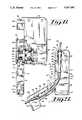
- FIG. 1is an exploded perspective elevational view of the housing assembly; swing arm; rotor; fluid delivery set and rotor shield; of the present invention with the drip chamber yoke removed;
- FIG. 2is a frontal elevational view of the assembled peristaltic pump in accordance with the present invention having the swing arm in the closed position;
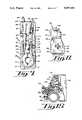
- FIG. 3is a side elevational view of the peristaltic pump in accordance with the present invention having the swing arm in the closed position;
- FIG. 4is a side elevational view of the peristaltic pump in accordance with the present invention having the swing arm in the open position;
- FIG. 5is a side elevational view of the peristaltic pump as shown in FIG. 4 and including a fluid delivery set loaded operationally mounted on the peristaltic pump in accordance with the present invention
- FIG. 6is a rear elevational view, partially in cross section, of the peristaltic pump in accordance with the present invention having the swing arm in the open position and showing the motor and rotor shaft of the present invention;
- FIG. 7is a side elevational view of the peristaltic pump in accordance with the present invention, as shown in FIG. 3, with the rotor shield removed; a fluid delivery set inserted in the peristaltic pump and the swing arm in the closed position;
- FIG. 8is an enlarged and elevational side view of the rotor shield taken generally along line 8--8 of FIG. 2;
- FIG. 9is a top elevational view of the peristaltic pump in accordance with the present invention with a fluid delivery set inserted therein and having the swing arm in the closed position;
- FIG. 10is an enlarged and elevated perspective view of the drip chamber yoke of the present invention as shown in FIG. 4;
- FIG. 11is a frontal elevational view of the charger unit of the present invention.
- FIG. 12is a rear elevational view of the charger unit of the present invention.
- FIG. 13is a frontal elevational view of the peristaltic pump mounted on the charger unit
- FIG. 14is a cross-sectional view of the charger unit taken along lines 14--14 of FIG. 11 showing the latch member of the present invention.
- FIG. 15is a partial cross-sectional view of the charger unit and pole clamp of the present invention.
- the preferred form of the present inventionincludes a rotary type of peristaltic pump 10 particularly adapted for the controlled delivery of enteral fluid to a patient.
- a rotary type of peristaltic pump 10particularly adapted for the controlled delivery of enteral fluid to a patient.
- the present inventionis described herein with reference to a rotary type of peristaltic pump, the present invention is readily adaptable for use with nearly any type of rotary or linear pump wherein it is desired to deliver a fluid at a controlled rate through a tubular member that is mounted along at least a portion of the pump.
- the peristaltic pump 10 of the present inventionconsists generally of a rectangularly-shaped housing assembly 12 having a swing arm 16 pivotally mounted on the lower side surface thereof.
- the swing arm 16includes carrying a motor 18 and partially enclosed rotor 14 mounted thereon as described hereinafter.
- the front surface 20 of the housing assembly 12is a generally flat and rectangularly-shaped surface which includes a control panel section 22 and an alpha numeric LED display section 24.
- the right side of the front surface 20includes an outwardly extending elongate upper flange 26 which extends downwardly from the top portion of the front surface 20 along approximately one-fourth of the length of the housing assembly 12 to shield the top portion of the drip chamber assembly 42, as described more fully hereinafter.
- An elongate lower flange 28extends outwardly along approximately one-fourth of the length of the housing assembly 12 near the approximate mid section of the housing assembly 12 to position the lower section of the drip chamber assembly 42 and a first portion of the silicone tube 44 of the fluid delivery set 40 as described more fully hereinafter.
- a first opening 30is located between the upper flange 26 and the lower flange 28 to allow the user to observe the flow of fluid in the drip chamber assembly 42 during operation of the peristaltic pump 10.
- a second opening 32is located beneath the lower flange 28 on the right side of the housing assembly 12 to allow the user to observe the operation of the rotor 14 of the present invention.
- the peristaltic pump 10 of the preferred embodimentis particularly designed for use with a conventional fluid delivery set 40 as disclosed in U.S. Pat. No. 4,913,703, which is incorporated herein by reference.
- the conventional fluid delivery set 40allows medical fluid to flow therethrough and generally consists of an elongate and flexible inlet tube 45 which is connected to a source of fluid (not shown) at one end and the top of the drip chamber assembly 42 at the other end.
- the drip chamber assembly 42preferably consists of a semi-rigid and cylindrically-shaped tapered member 46 having a top cap member 47 attached to the top end thereof.
- An annular rim 50is formed as part of the cap member 47 and is located along the top surface of the tapered member 46.
- a top tubular member 48extends downwardly from the cap member 47 into the interior of the drip chamber assembly 42.
- a lower tubular member 52is centrally positioned on the bottom end 53 of the tapered member 46 to extend downwardly therefrom.
- the lower tubular member 52 on the drip chamber assembly 42is connected to the first end of the silicone tube 44.
- the silicone tube 44preferably consists of a predetermined length of resilient and compressible silicone tubing having a first predetermined internal diameter in the relaxed condition and a second predetermined internal diameter in the stretched condition as described hereinafter.
- the second end of the silicone tube 44is connected to a circular mounting or connector member 54 which includes top and bottom tubular members, 56 and 58 respectively, which extend upwardly and downwardly therefrom and an enlarged annular flange 60 which is positioned between the top and bottom tubular members, 56 and 58,
- the annular flange 60includes a cylindrically-shaped magnet 62 thereon, the function of which is described more fully hereinafter.
- the magnet 62may be obtained from a variety of sources; however, it has been found that a material composed of 88% strontium ferrite is particularly suitable for use in the present invention. This material includes 12% of #6 nylon and is available from Tengam Inc. of Otsego, Mich.
- the magnet 62is magnetized in the axial direction to a magnetic strength of approximately 400 to 500 gauss at the circumferential surface.
- An elongate outlet tube 64includes a first end which is connected to the top tubular member 56 of the mounting member 54 and a second end (not shown) which is adapted to deliver the medical fluid to the patient.
- the upper flange 26 on the side surface of the housing assemblyincludes a semi-circularly-shaped top lip 34 which extends rearwardly and inwardly from the top of the upper flange 26.
- the top lip 34is shaped to protect the inlet tube 35 near the top tubular member 48 of the drip chamber assembly 42 and assist in the loading of the drip chamber assembly 42 onto the peristaltic pump 10 when the fluid delivery set 40 is mounted on the peristaltic pump 10 as described hereinafter.
- the upper flange 26includes an elongate and semi-circular drip chamber yoke retaining flange 36 which consists of a set of flanges and recesses which are located rearwardly of the front surface 20 of the upper flange 26 to retain the drip chamber yoke 37 in fluid tight communication with the housing assembly 12 to allow the user to clean the drip chamber recess 39 without exposing the electronics in the housing assembly 12 to the cleaning fluid.
- the retaining flange 36is positioned on the upper flange 26 to locate the drip chamber yoke 37 adjacent to the drop forming bottom end of the top tubular member 48 on the drip chamber assembly 42 as described hereinafter.
- a generally rectangularly-shaped tube retaining flange 38extends rearwardly from the outer surface of the yoke retaining flange 36.
- the tube retaining flange 38is oriented in a spaced apart relationship with the housing assembly 12 to retain a portion of the outlet tube 64 from the fluid delivery set 40 adjacent thereto when the swing arm 16 is in the closed position as described hereinafter.
- a locking lip 35is positioned rearwardly of the yoke retaining flange 36 and is oriented to extend perpendicular to and upwardly from the tube retaining flange 38.
- the locking lip 35is adapted to receive a complementary locking lip 66 on the swing arm 16 therein.
- the locking lip 35 on the housing assembly 12 and the locking lip 66 on the swing arm 16may be replaced by nearly any type of positive latch including the type of latch mechanism having one or more magnets thereon to ensure retention of the swing arm 16 in the closed position as described hereinafter.
- the drip chamber yoke 37 of the present inventionis a rigid and generally rectangularly-shaped member having a drip chamber receiving recess 39 along the interior surface thereof.
- the top of the receiving recess 39includes an enlarged and generally oblong shoulder area 41 which is adapted to receive the relatively rigid annular rim 50 of the drip chamber assembly 42 thereon as described hereinafter.
- the internal surface of the receiving recess 39 below the shoulder area 41is semi-circularly-shaped with a radius of approximately 240° to retain the drip chamber assembly 42 centered therein and to decrease the likelihood that the drip chamber assembly 42 will be inadvertently pulled from the optimal vertical alignment in the receiving recess 39 during operation of the present invention.
- the lengthwise dimension of the receiving recess 39forms an angular recess which gradually tapers inwardly to conform to the shape of the tapered member 46 of the drip chamber 42.
- two opposingly oriented pairs of openings 43are located in the side walls of the drip chamber yoke 37.
- the openings 43are designed to house at least one set of drop sensing emitters and detectors (not shown).
- the drop sensing emitters and detectorsare aligned to form an optical path which detects drops of fluid immediately after they fall from the bottom end of the top tubular member 48 in the drip chamber assembly 42.
- the peristaltic pump 10may not detect the formation of drops in the drip chamber assembly 42 and the motor 18 of the peristaltic pump 10 will stop operating and indicate to the operator that there is a flow error. If the emitters and detectors are positioned too low with respect to the bottom end of the top tubular member 48, the peristaltic pump 10 may not detect the drops of medical fluid because the lower portion of the tapered member 46 may become coated with enteral fluid due to the splashing of the drops as they fall in the drip chamber assembly 42. In this situation, the peristaltic pump 10 will then stop operating and indicate to the user that there is a flow error because the fluid drops are not being sensed by the emitters and detectors.
- the usermay also experience a flow error alarm if the peristaltic pump 10 is tilted so that the drops in the drip chamber assembly 42 do not fall through the optical path of the emitters and detectors. If the emitters and detectors are positioned too far below the bottom end of the top tubular member 48 and the peristaltic pump 10 is not maintained in a vertical position, the falling drops of medical fluid may not pass through the optical path of the emitters and detectors and the peristaltic pump 10 will discontinue operating and indicate to the user that there is a flow error.
- the drip chamber yoke 37 of the present inventionis designed to ensure that the bottom end of the top tubular member 48 is optimally positioned adjacent to the optical path created by the emitters and detectors.
- the length of the drip chamber assembly 42may also vary between individual fluid delivery sets 40.
- the drip chamber assemblyis retained in position on the peristaltic pump by inserting the bottom end of the drip chamber assembly into a first recess on the housing assembly and there is nothing to ensure that the bottom end of the top tubular member in the drip chamber assembly 42 is optimally positioned so that the drop will pass through the optical path.
- the present inventionis designed to accommodate variations in the length of drip chamber assemblies 42 without adversely affecting the drop sensing operation of the peristaltic pump 10 by ensuring that the emitters and detectors are optimally positioned with respect to the bottom end of the top tubular member 48 while not adversely affecting the distance the silicone tube 44 is stretched about the rotor 14.
- the drip chamber assembly 42 of the preferred fluid delivery set 40has a nominal length of 2.5075 inches and cumulative dimensional tolerance of ⁇ 0.035 inches.
- the drip chamber yoke 37 of the present inventionallows the bottom end 53 of fluid delivery sets 40 which have a longer drip chamber assembly 42 to rest on the first mounting recess 68 so that a minimal amount of the top end of the drip chamber assembly 42 will extend above the shoulder area 41 of the drip chamber yoke 37 and the optical path of the emitters and detectors will be only slightly below the optimal position with respect to the bottom end of the top tubular member 48.
- the fluid delivery sets 40 which have a the shorter drip chamber assembly 42will be supported in the drip chamber yoke 37 by contact between the annular rim 50 of the drip chamber assembly 42 in the shoulder area 41 of the receiving recess 39 so that the bottom end of the top tubular member 48 will be optimally positioned with respect to the optical path of the emitters and detectors.
- the silicone tube 44When the shorter drip chamber assembly 42 is supported by the shoulder area 41 in the drip chamber yoke 37, the silicone tube 44 may be stretched slightly more than when the bottom end 53 of the drip chamber assembly 42 is supported in the first mounting recess 68; however, because the stretching of the silicone tube 44 is distributed over the entire length of the silicone tube 44, the internal diameter of the silicone tube 44 is not significantly affected and the amount of enteral fluid delivered by each rotation of the rotor 14 on the peristaltic pump 10 is not adversely affected.
- an oblong and generally semicircular first mounting recess 68is positioned behind the front surface of the lower flange 28 and slightly below the top surface thereof.
- the first mounting recess 68includes a grooved shoulder area 69 which is sized to receive the bottom end 53 of the drip chamber assembly 42 therein while allowing the lower tubular member 52 of the drip chamber assembly 42 to extend therethrough.
- a first set loading channel 70extends downwardly from the first mounting recess 68 to the top end of the second opening 32 which begins slightly below the top of the rotor 14.
- a raised frictional detent 71is located beneath the lower flange 28 near the front surface of the housing assembly 12 to releasably retain the swing arm 12 in the open position as described hereinafter.
- the rotor 14 of the present inventionis a cylindrical member having inner and outer enlarged flanges 72 and 74, respectively. As described above, the rotor is designed to extend from the side surface of the housing assembly 12.
- the enlarged flanges, 72 and 74include three equally spaced rollers 76 extending therebetween along the circumference of the rotor 14.
- the rollers 76are mounted on metal pins which extend between the inner and outer enlarged flanges 72 and 74 so that the rollers 76 rotate freely when they are placed in contact with the silicone tube 44 of the fluid delivery set 40 as described hereinafter.
- the rotor 14is mounted on an inwardly directed central shaft 78 (FIG.
- a circular recess 80is located on the central axis of the rotor 14 along the outer surface of the outer enlarged flange 74, the function of which is described hereinafter.
- the interior of the housing assembly 12includes the electronic circuitry (not shown) of the peristaltic pump 10 and a pair of annular grooves 82 located inwardly from the rotor 14 as shown in FIG. 1.
- the swing arm 16 of the present inventionincludes a hollow and cylindrically-shaped bearing sleeve 84 which extends inwardly from the side surface of the housing assembly 12.
- the motor 18 of the present inventionis frictionally retained in the bearing sleeve 84 so that the motor 18 rotates as the swing arm 16 is rotated between the open and closed positions.
- the external surface of the bearing sleeve 84includes a pair of inner and outer circular flanges 85 and 86, respectively, which are received in the annular grooves 82 on the housing assembly 12 to allow rotational movement of the swing arm 16 while preventing longitudinal movement of the swing arm 16 and motor 18 with respect to the housing assembly 12.
- the outer circular flange 86includes an outwardly directed lip 88 which encircles the circumference of the inner flange 72 on the rotor 14.
- the bottom of the lip 88is positioned slightly inwardly from the outer surface of the inner flange 72 and increases in outward extension from the bottom of the rotor 14 to the top of the rotor 14 wherein the lip 88 extends outwardly from the outer surface of the inner flange 72 to assist in the placement of the silicone tube 44 around the rotor 14 as described hereinafter.
- a second set loading channel 90is formed along the lengthwise dimension of the swing arm 16 by first and second wall members, 92 and 94 which extend outwardly from the inner surface of the swing arm 16.
- the second set loading channel 90is generally U-shaped and includes a top semi-circular opening 96 through which the outlet tube 64 of the fluid delivery set 40 extends.
- a pair of inwardly directed ridges 98are positioned slightly below the top surface 116 of the swing arm 16. The ridges 98 extend inwardly approximately two thirds of the way into the second set loading channel 90 so that the exterior portion of this area of the second set loading channel 90 is narrower than the interior portion of this section of the loading channel 90.
- the width of the exterior surface of the second set loading channel 90gradually increases from the ridges 98 near the top surface 116 of the swing arm 16 to a location approximately one-fourth of the distance along the swing arm 16 to a lower enlarged width area defined herein as the mounting member receiving section 110 of the second set loading channel 90.
- the receiving section 110 of the second set loading channel 90is an elongate and generally rectangularly-shaped recess in the swing arm 16.
- the receiving section 110is sized to conveniently receive the mounting member 54 and the second end of the silicone tube 44 of the fluid delivery set 40 therein.
- the bottom end of the receiving section 110is aligned with a lower silicone tube channel 115 which forms the lower section of the second set loading channel 90.
- the top end of the silicone tube channel 115includes a semi-circular and reduced width second mounting recess 112 which forms a shoulder area 111 in the second set loading channel 90.
- the shoulder area 111is adapted to receive the bottom of the mounting member 54 thereon as described hereinafter.
- the silicone tube channel 115includes a gradually tapered section 113 on the second wall member 94 which tapers rearwardly and downwardly along the swing arm 16 to increase the width of the second set loading channel 90 from a location below the second mounting recess 112 to the bottom of the second wall member 94.
- the second wall member 94is designed to end below the top of the rotor 14 while the first wall member 92 extends generally linearly downwardly from the second mounting recess 112 to a location adjacent the top of the rotor 14 when the swing arm 16 is in the closed position as described hereinafter.
- the inner surface of the second set loading channel 90includes a sensor opening 114 located immediately above and adjacent to the second mounting recess 112 to allow a magnetic sensor 117 to sense when the mounting member 54 is inserted in the swing arm 16 and the swing arm 16 is moved to the closed position as described hereinafter.
- the magnetic sensor 117 of the present inventionis preferably a magneto resistive switching element, such as part No. SS21PE available from Microswitch Inc. of Freeport, Ill. which is designed to provide an output of plus 5 volts when not in the presence of a magnetic field and zero volts when in the presence of either polarity of a magnetic field such as the magnetic field created by magnet 62.
- the inner surface of the swing arm 16also includes second opening 118 located below the top surface 116 of the swing arm 16 and above the receiving section 110 of the second set loading channel 90.
- the second opening 118is sized to receive the retaining flange 38 of the housing assembly 12 therethrough when the swing arm 16 is in the closed position.
- the top surface 116 of the swing arm 16includes a locking lip 66 extending downwardly and linearly along the inner surface of the top surface 116 so that the locking lip 66 contacts the locking lip 39 on the housing assembly 12 to releasably retain swing arm 16 in the closed position.
- the top of the swing arm 16also includes a flat and generally rectangularly shaped drip chamber shade 120 (FIGS. 4 and 5) which is designed to protect the emitters and detectors in the drip chamber yoke 37 and the top of the drip chamber assembly 42 from interference by ambient light when the swing arm 16 is in the closed position as described hereinafter.
- the preferred embodiment of the present inventionincludes a rotor shield 122 to facilitate the loading of the fluid delivery set 40 around the rotor 14 and to protect the rotor 14 and shaft 78 from accidental damage caused by contact with the rotor 14 during movement of the peristaltic pump 10.
- the rotor shield 122includes a mounting surface 123 which is attachable to the side surface of the housing assembly 12 at a location on the housing assembly 12 which is oriented rearwardly from the lower flange 28.
- the rotor shield 122is designed to be removable from the housing assembly 12 so that the rotor 14 and rotor shield 122 may be cleaned without exposing the electronics in the housing assembly 12 to the cleaning fluid.
- the mounting surface 123extends outwardly therefrom to a generally planar portion of the rotor shield 122 which is generally aligned with the outer surface of the swing arm 16.
- the planar surface of the rotor shield 122consists generally of a flat and rectangularly-shaped upper section 125 and an oblong-shaped lower section 127.
- the upper section 125 and the lower section 127 of the rotor shield 122are positioned along the side surface of the housing assembly 12 to extend downwardly from the lower flange 28 and along the side surface of the housing assembly 12 to a location spaced outwardly from the outer flange 74 of the rotor 14.
- the inner surface of the rotor shield 122 near the top of the upper section 125includes an inwardly directed and generally linear top flange 124 which extends inwardly from the rotor shield 122 to a location adjacent to the top of the second mounting recess 112 on the swing arm 16 when the swing arm 16 is in the closed position.
- the top flange 124 and the second mounting recess 112form a generally closed recess having a closed section only slightly larger than the diameter of the mounting member 54.
- the top of the top flange 124also includes a chamfer thereon to facilitate the movement of the mounting member 54 into the second mounting recess 112 as the swing arm 16 is moved to the closed position as described hereinafter.
- An elongate and generally L-shaped intermediate flange 126extends inwardly from the approximate intersection of the upper section 125 and lower section 127 of the rotor shield 122.
- the intermediate flange 126extends inwardly from the rotor shield 122 to a location which is adjacent to the top of the rotor 14 and extends inwardly of the outer flange 74 of the rotor 14.
- the rear end 128 of the intermediate flange 126is oriented at an angle of approximately 65° from the main portion thereof and extends downwardly therefrom to a location adjacent to the tapered section 113 on the second wall member 94 of the swing arm 16 when the swing arm 16 is in the closed position.
- a centrally positioned set of stiffening ribs 130extend inwardly from the center of the lower section 127 of the rotor shield 122.
- the ribs 130preferably include four laterally extending arms which are designed to be normally spaced apart from the circular recess 80 located on the outer flange 74 of the rotor 14.
- the ribs 130are designed to reduce the bending forces applies to the lower section 127 of the rotor shield 122 when an external force is applied to the rotor shield 122.
- a circular protrusion 132extends inwardly from the center of the ribs 130.
- the orientation of the ribs 130 with respect to the circular recess 80decreases the likelihood that the shaft 78 of the rotor 14 will be bent or damaged by contact between the side of the peristaltic pump 10 or rotor 14 and an external object.
- the circular protrusion 132is aligned with the axial center of the rotor 14 and allows the rotor 14 to continue rotating with only a slight increase in resistance to rotation when the side of the peristaltic pump 10 rests against an object. Therefore, the operation of the motor 14 of the present invention will not be significantly affected by moderate contact with an external object against the side of the peristaltic pump 10 of the type which may occur during ambulatory use.
- the bottom edge of the rotor shield 122includes an inwardly directed bottom flange 134 which has an apex 136 thereon located approximately midway along the lengthwise dimension of the bottom flange 134.
- the apex 136preferably extends inwardly from the rotor shield 132 to a location adjacent to the inner surface of the outer flange 74 on the rotor 14 and is designed to guide the fluid delivery set 40 toward the center of the rollers 76 on the rotor 14 on those occasions when the fluid delivery set 40 is not loaded completely flat in the first and second set loading channels 70 and 90, as described hereinafter.
- the installation of the fluid delivery set 40 on the peristaltic pump 10 of the present inventionis relatively simple and the likelihood that the fluid delivery set 40 will be improperly mounted on the peristaltic pump 10 is significantly reduced as compared to currently available peristaltic pumps.
- the swing arm 16is rotated to the open or loading position so that the inner surface of the swing arm 16 contacts the frictional detent 71 as shown in FIG. 4.
- the drip chamber receiving recess 39; the first mounting recess 68; the first set loading channel 70 on the housing assembly 12 and the entire second set loading channel 90 on the swing arm 16are exposed to allow for the insertion of the fluid delivery set 40 therein.
- the drip chamber assembly 42 of the fluid delivery set 40is placed on the housing assembly 12 by inserting the annular rim 50 of the drip chamber assembly 42 below the top lip 34 of the housing assembly 12 so that the bottom end 53 of the drip chamber assembly 42 is positioned above the first mounting recess 68.
- the mounting member 54is then inserted into the receiving section 110 of the second set loading channel 90 on the swing arm 16 such that the silicone tube 44 is loosely positioned near the front surface of the rotor 14.
- the outlet tube 64is pulled inwardly between the ridges 98 into the wider interior of the second set loading channel 90 on the swing arm 16.
- the width of the silicone tube channel 115 and the semi-circular opening 96are sized so that the mounting member 54 will only fit in the receiving section 110 of the second set loading channel 90. Additionally, the second set loading channel 90 on the swing arm 16 is sized so that it will not accept the drip chamber assembly 42 therein and therefore, the user cannot accidentally reverse the drip chamber assembly 42 and mounting member 54 while loading the fluid delivery set 40 on the present invention.
- the swing arm 16 of the present inventionis particularly designed so that the swing arm 16 rotates generally about the axial center of the rotor 14 from the open position (FIGS. 4, 5 and 6) to the closed position (FIGS. 2, 3 and 7).
- the orientation of the swing arm 16 about the axial center of the rotorincreases the relative distance between the first mounting recess 68 on the housing assembly 12 and the second mounting recess 112 on the swing arm 16 through the first set loading channel 70 and the silicone tube channel 115 as the swing arm 16 is moved from the open position to the closed position.
- the silicone tube 44 of the fluid delivery set 40will remain in the relaxed and unstretched condition near the front of the rotor 14 until the swing arm 16 is rotated to a position generally perpendicular to the rear surface of the peristaltic pump 10. As the swing arm 16 reaches this position, the silicone tube 44 will contact the rollers 76 on the rotor 14.
- the silicone tube 44will contact the bottom flange 134 on the rotor shield 122 and slide inwardly as the swing arm 16 is rotated so that the silicone tube 44 is properly positioned about the rollers 76 on the rotor 14.
- the mounting member 54will be drawn downwardly in the receiving section 110 of the loading channel 90 until the bottom surface of the mounting member 54 is positioned inwardly of the top flange 134 on the rotor shield 122 to contact the shoulder area 111 in the top of the second mounting recess 112.
- the drip chamber assembly 42will be pulled downwardly in the drip chamber receiving recess 39 until the annular rim 50 of the drip chamber assembly 42 contacts the shoulder area 41 in the drip chamber yoke 37 or until the bottom end 53 of the tapered member 46 contacts the shoulder area 69 in the top of the first mounting recess 68.
- the silicone tube 44is stretched and compressed around the rollers 76 on the rotor 14.
- the locking lip 66 on the swing arm 16will contact the locking lip 35 on the housing assembly 12 so that the swing arm 16 will be frictionally retained in the closed position.
- the inlet tube 45extends through an opening in the top surface of the housing assembly 12 formed by adjacent semi-circular edges of the swing arm 16 and the top lip 34 of the upper flange 26 (FIG. 9).
- the bottom end of the top tubular member 48 of the drip chamber assembly 42is positioned slightly above the optical path of the emitters and detectors in the drip chamber yoke 37 so that the falling drops of fluid may be sensed by the emitters and detectors.
- the drip chamber shield 120encloses the outer side of the top portion of the drip chamber assembly 42 to prevent ambient light from interfering with the operation of the emitters and detectors and to assist in retaining the tapered member of the drip chamber assembly 42 in the receiving recess 39 of the drip chamber yoke 37.
- the bottom end 53 of the drip chamber assembly 42is positioned in the shoulder area 41 of the first mounting recess 68.
- the silicone tube 44is connected to the lower tubular member 52 of the drip chamber assembly 42 and extends downwardly from the first mounting recess 68 and through the first set loading tube channel 70 to contact one or more rollers 76 on the rotor 14.
- the silicone tube 44is compressed around the rollers 76 so that a predetermined quantity of fluid is trapped between the spaced apart rollers 76.
- the silicone tube 44also extends upwardly from the rotor 14 and passes rearwardly of the intermediate flange 126 on the rotor shield 122. The silicone tube 44 then extends through the silicone tube channel 115 to the second mounting recess 112.
- the stretching of the silicone tube 44causes the mounting member 54 to seat in the shoulder area 111 in the second mounting recess 112 and behind the top flange 124 of the rotor shield 122 so that the magnet 62 on the annular flange 60 is positioned adjacent the sensor opening 114 in the swing arm 16.
- the positioning of the magnet 62 adjacent to the sensor opening 114allows the magnetic sensor 117 in the housing assembly 12 to sense the presence of the magnet 62 and enable the operation of the motor 18 when the magnet 62 is sensed.
- the outlet tube 64 of the fluid delivery set 40extends upwardly through the receiving section 110 of the second set loading channel 90 and passes behind the retaining flange 38 on the housing assembly 12 and the ridges 98 on the swing arm 16.
- the outlet tube 64would oftentimes be pinched at the connection of the outlet tube 64 and the top tubular member 56 of the mounting member 54 if the patient or the peristaltic pump were moved. This caused an increase in the back pressure in the silicone tube 44 so that the rollers 76 do not properly close or compress the silicone tube 44.
- the amount of fluid actually delivered to the patient through the fluid delivery set 40 by the peristaltic pump 10decreases as the back pressure in the silicone tube 44 increases.
- the outlet tube 64 in the present inventionis designed to extend through the second set loading channel 90 as described above to prevent the outlet tube 64 from being pinched at the connection of the outlet tube 64 and the top tubular member 56 on the mounting member 54. Additionally, the sides of the second set loading channel 90 at the top surface 116 of the swing arm 16 are chamfered to decrease the likelihood that the flow of fluid will be impaired by pinching the outlet tube 64 against the swing arm 16.
- the present inventionalso includes a number of other features which are designed to prevent the swing arm from closing if the fluid delivery set 40 is improperly positioned in the housing assembly 12 and the swing arm 16. If the user inserts the mounting member 54 into the silicone tube channel 115 rather than in the receiving section 110, the rear end 128 of the intermediate flange 126 and the tapering section 113 of the second wall member channel 94 will push the circular mounting member 54 downwardly from the silicone tube channel 115 so that it will be visible along rear surface of the rotor and the magnet 62 will not be sensed by the magnetic sensor 177 to prevent the motor 18 from operating.
- the outlet tube 64will be pinched against the second wall member 94 of the swing arm 16 by the retaining flange 38 in the housing assembly 12 so that fluid flow will be restricted through the outlet tube 64. If the user places the silicone tube 44 in front of the rotor shield 122 rather than behind it, the silicone tube 44 will be pinched between the rear end 128 of the intermediate flange on the rotor shield 122 and the tapering section 113 on the second wall member 94.
- the receiving section 110 of the loading channel 90is sized so that the user cannot inadvertently load the drip chamber assembly 42 in the receiving section 110 of the second set loading channel 90 because the drip chamber assembly 42 is too large to fit in the receiving section 110 of the second set loading channel 90.
- the present inventionalso includes a charger unit 150 which is adapted to releasably receive the peristaltic pump 10 thereon.
- the charger unit 150generally includes a base member 152 which is sized to slidably receive the bottom of the housing assembly 12 therein and an upwardly extending and generally rectangularly-shaped charger unit body member 154.
- the base member 152extends forwardly of the lower surface of the body member 154 and includes an upwardly extending forward lip 156 on the front surface thereof.
- a forwardly extending side lip 158extends upwardly along the left side of the base member 152 and forwardly projects from the body member 154 to receive the front surface 20 of the housing assembly 12 therebehind.
- a latch opening 160is located on the top surface of the base member 152 near the back of the base member 152 and adjacent to the side lip 158. Additionally, as shown in FIG. 14, a latch release opening 161 is located along the outer surface of the lower portion of the side lip 158.
- the front surface of the body member 154includes an elongate and generally rectangular slide member 162 which extends forwardly from the body member 154 a short distance below the approximate midpoint of the body member 154. As shown in FIG. 11, the slide member 154 extends horizontally from the intersection of the body member 154 and the side lip 158 to a rounded second end which is located near the opposite side of the body member 154.
- a conductive array of contact members 164are oriented generally perpendicular to the slide member 162 and extend forwardly from the body member 154 along the intersection of the body member 154 and the side lip 158 below the slide member 162.
- the rear surface of the body member 154includes a lower semicircular support pole receiving surface 166 and a generally T-shaped pole clamp 168.
- the receiving surface 166is positioned on the same side of the body member 154 as the side lip 158 and extends upwardly along the rear surface of the body member 154 approximately two-thirds of the distance along the member 154.
- the pole clamp 168includes an elongate and horizontally oriented leg member 170 having a leaf spring retaining recess 171 therein; a threaded shaft member 172 extending therethrough and a vertically oriented clamping member 174 having a semi-circular recess on its interior surface.
- the retaining recess 171includes an outwardly biased leaf spring 173 which includes a first leg retained in the retaining recess 171 and a second leg which is biased against the rear surface of the charger unit 150.
- an elongate and semi-rigid latch member 176is enclosed in a latch channel 178 located along the bottom surface of the base member 152.
- the latch member 176is oriented generally parallel to the forward lip 156 and is positioned rearwardly thereof in the latch channel 178 located in the base member 152.
- the right side of the latch member 176includes a mounting surface 180 which is adapted to be fixedly mounted to the bottom surface of the base member 152 near the right side of the latch channel 178.
- a raised retaining member 182extends upwardly from the latch member 176 to extend through the latch opening 160 on the top surface of the base member 152.
- the retaining member 182includes a gradually upwardly sloping first surface which is nearest to the mounting surface 180 and a second surface which is oriented generally perpendicular to the bottom surface of the base member 152.
- a latch release member 183extends upwardly from the left side of the latch member 176 to extend through the release opening 161 located on the outer surface of the side lip 158.
- the peristaltic pump 10When the user desires to recharge the peristaltic pump 10; operate the peristaltic pump 10 with an external power source (not shown) or support the peristaltic pump 10 on a support pole 190, the peristaltic pump 10 is initially aligned with the right side of the charger unit 150 so that the elongate slide recess 184 (FIG. 6) on the rear surface of the housing assembly 12 is aligned with the slide member 162 on the forward surface of the body member 154. As the peristaltic pump 10 is moved to the left, the slide member 162 will align the contact members 164 on the charger unit 150 with contact members 186 (FIG. 6) on the rear side surface of the housing assembly 12 opposite the rotor 14.
- the retaining member 182 on the latch member 176will contact and enter the latch recess 188 (FIG. 6) on the bottom surface of the housing assembly 12 to releasably retain the peristaltic pump 10 on the charger unit 150.
- the contact members 164 on the charger unitwill be aligned with and in operative contact with the contact members 186 on the housing assembly 12 to allow the charger unit 150 to charge the batteries (not shown) and provide operating power to the peristaltic pump 10.
- the usermay release the peristaltic pump 10 from the charger unit 150 by depressing the release member 183 on the outer surface of the side lip 158.
- the release member 183is depressed, the retaining member 182 is biased downwardly in the channel 178 so that the retaining member 182 is released from the latch recess 188 on the bottom surface of the housing assembly 12.
- the peristaltic pump 10may then be moved to the right and removed from the charger unit 150.
- the peristaltic pump 10is initially inserted into the charger unit 150 as described above.
- the shaft member 172 on the pole clamp 168is then unthreaded to allow the support pole to be inserted between the clamping member 174 and the rear surface of the body member 154 so that the support pole is aligned in the receiving surface 166 on the body member 154 and in compressive contact with a flexible pole receiving flange 189 on the inner surface of the clamping member 174.
- the receiving flange 189includes an interiorly directed flexible edge or bumper which is particularly designed to be compressed against the support pole 190 to frictionally retain the peristaltic pump 10 and charger unit 150 in position on the support pole 190.
- the leaf spring 173pivotally biases the clamping member 174 outwardly from the rear surface of the body member 154 so that the right end of the leg member 170 pivotally maintains contact with the rear surface of the body member 154.
- the pole clamp 168pivotally contacts the support pole 190 so that the receiving flange 189 of the clamping member 174 pivotally presses the support pole 190 against the rear surface of the body member 154 in the receiving surface 166 and the leg member 170 contacts the rear surface of the body member 154.
- the swing arm 16 of the present inventionis fully operational when the peristaltic pump 10 is mounted on the charger unit 150 and when the combination is mounted on a support pole 190.
Landscapes
- Health & Medical Sciences (AREA)
- Engineering & Computer Science (AREA)
- Hematology (AREA)
- General Health & Medical Sciences (AREA)
- Vascular Medicine (AREA)
- Anesthesiology (AREA)
- Biomedical Technology (AREA)
- Heart & Thoracic Surgery (AREA)
- Veterinary Medicine (AREA)
- Life Sciences & Earth Sciences (AREA)
- Animal Behavior & Ethology (AREA)
- Public Health (AREA)
- General Engineering & Computer Science (AREA)
- Mechanical Engineering (AREA)
- Infusion, Injection, And Reservoir Apparatuses (AREA)
- Reciprocating Pumps (AREA)
- External Artificial Organs (AREA)
- Medicines Containing Material From Animals Or Micro-Organisms (AREA)
- Pharmaceuticals Containing Other Organic And Inorganic Compounds (AREA)
Abstract
Description
Claims (39)
Priority Applications (19)
| Application Number | Priority Date | Filing Date | Title |
|---|---|---|---|
| US07/538,791US5057081A (en) | 1990-06-15 | 1990-06-15 | Peristaltic infusion device |
| US07/663,964US5133650A (en) | 1990-06-15 | 1991-03-01 | Infusion device rotor shield |
| US07/663,965US5181842A (en) | 1990-06-15 | 1991-03-01 | Peristaltic infusion device |
| US07/675,774US5158528A (en) | 1990-06-15 | 1991-03-27 | Peristaltic infusion device and charger unit |
| PCT/US1991/003938WO1991019523A1 (en) | 1990-06-15 | 1991-06-04 | Peristaltic infusion device |
| AU80039/91AAU650461B2 (en) | 1990-06-15 | 1991-06-04 | Peristaltic infusion device |
| EP91911370AEP0533783B1 (en) | 1990-06-15 | 1991-06-04 | Peristaltic infusion device |
| JP51099791AJP3174572B2 (en) | 1990-06-15 | 1991-06-04 | Peristaltic infusion device |
| DE69124373TDE69124373T2 (en) | 1990-06-15 | 1991-06-04 | PERISTALTIC INFUSION DEVICE |
| KR1019920703242AKR100214929B1 (en) | 1990-06-15 | 1991-06-04 | Peristaltic injection device |
| CA002085467ACA2085467C (en) | 1990-06-15 | 1991-06-04 | Peristaltic infusion device |
| AT91911370TATE147998T1 (en) | 1990-06-15 | 1991-06-04 | PERISTALTIC INFUSION DEVICE |
| IL9842691AIL98426A (en) | 1990-06-15 | 1991-06-10 | Peristaltic infusion device |
| IE198191AIE77160B1 (en) | 1990-06-15 | 1991-06-11 | Peristaltic Infusion Device |
| MX026229AMX173641B (en) | 1990-06-15 | 1991-06-13 | DEVICE FOR THE INFUSION OF FLUIDS IN THE BODY OF A PATIENT |
| US07/719,220US5127908A (en) | 1990-06-15 | 1991-06-21 | Peristaltic infusion device |
| US07/720,331US5147312A (en) | 1990-06-15 | 1991-06-25 | Peristaltic infusion device drip chamber yoke |
| NO924855ANO300446B1 (en) | 1990-06-15 | 1992-12-15 | Peristaltic infusion device, and method of operating a fluid delivery kit thereon |
| FI925701AFI105529B (en) | 1990-06-15 | 1992-12-15 | Peristaltic infusion device |
Applications Claiming Priority (1)
| Application Number | Priority Date | Filing Date | Title |
|---|---|---|---|
| US07/538,791US5057081A (en) | 1990-06-15 | 1990-06-15 | Peristaltic infusion device |
Related Child Applications (8)
| Application Number | Title | Priority Date | Filing Date |
|---|---|---|---|
| US07/663,965Continuation-In-PartUS5181842A (en) | 1990-06-15 | 1991-03-01 | Peristaltic infusion device |
| US07/663,964Continuation-In-PartUS5133650A (en) | 1990-06-15 | 1991-03-01 | Infusion device rotor shield |
| US07/675,774Continuation-In-PartUS5158528A (en) | 1990-06-15 | 1991-03-27 | Peristaltic infusion device and charger unit |
| US68376091AContinuation-In-Part | 1991-04-11 | 1991-04-11 | |
| US07689597Continuation-In-Part | 1991-04-19 | ||
| US07/719,220ContinuationUS5127908A (en) | 1990-06-15 | 1991-06-21 | Peristaltic infusion device |
| US07/720,331DivisionUS5147312A (en) | 1990-06-15 | 1991-06-25 | Peristaltic infusion device drip chamber yoke |
| US07764402Continuation-In-Part | 1991-09-23 |
Publications (1)
| Publication Number | Publication Date |
|---|---|
| US5057081Atrue US5057081A (en) | 1991-10-15 |
Family
ID=24148427
Family Applications (1)
| Application Number | Title | Priority Date | Filing Date |
|---|---|---|---|
| US07/538,791Expired - LifetimeUS5057081A (en) | 1990-06-15 | 1990-06-15 | Peristaltic infusion device |
Country Status (14)
| Country | Link |
|---|---|
| US (1) | US5057081A (en) |
| EP (1) | EP0533783B1 (en) |
| JP (1) | JP3174572B2 (en) |
| KR (1) | KR100214929B1 (en) |
| AT (1) | ATE147998T1 (en) |
| AU (1) | AU650461B2 (en) |
| CA (1) | CA2085467C (en) |
| DE (1) | DE69124373T2 (en) |
| FI (1) | FI105529B (en) |
| IE (1) | IE77160B1 (en) |
| IL (1) | IL98426A (en) |
| MX (1) | MX173641B (en) |
| NO (1) | NO300446B1 (en) |
| WO (1) | WO1991019523A1 (en) |
Cited By (57)
| Publication number | Priority date | Publication date | Assignee | Title |
|---|---|---|---|---|
| US5168892A (en)* | 1991-04-03 | 1992-12-08 | Sherwood Medical Company | Adjustable carrying case for a fluid delivery system |
| US5170817A (en)* | 1991-04-03 | 1992-12-15 | Sherwood Medical Company | Support device for fluid delivery system and case therefore |
| US5181842A (en)* | 1990-06-15 | 1993-01-26 | Sherwood Medical Company | Peristaltic infusion device |
| US5236004A (en)* | 1991-04-03 | 1993-08-17 | Sherwood Medical Company | Ambulatory support device for a fluid delivery system |
| US5250027A (en)* | 1991-10-08 | 1993-10-05 | Sherwood Medical Company | Peristaltic infusion device with backpack sensor |
| USD342231S (en) | 1991-04-19 | 1993-12-14 | Sherwood Medical Company | Charger unit for a peristaltic infusion pump |
| US5281111A (en)* | 1992-12-23 | 1994-01-25 | Abbott Laboratories | Cartridge for drug infusion pump |
| US5326236A (en)* | 1993-09-24 | 1994-07-05 | Abbott Laboratories | Compliant rotor for an improved cartridge for drug infusion pump |
| WO1996017174A1 (en)* | 1994-11-28 | 1996-06-06 | Sherwood Medical Company | Apparatus for delivering fluid to a patient |
| US5569026A (en)* | 1992-06-18 | 1996-10-29 | Storz Endoskop Gmbh | Tube pump in which tube can be inserted only in one direction |
| GB2312022A (en)* | 1996-04-10 | 1997-10-15 | Baxter Int | Medical infusion pump |
| US5681294A (en)* | 1995-09-21 | 1997-10-28 | Abbott Laboratories | Fluid delivery set |
| USD397784S (en) | 1995-09-21 | 1998-09-01 | Abbott Laboratories | Fluid delivery unit |
| US5807333A (en)* | 1995-09-21 | 1998-09-15 | Abbott Laboratories | Peristaltic pump and fluid delivery set |
| USD398985S (en) | 1995-09-21 | 1998-09-29 | Abbott Laboratories | Fluid delivery set |
| US5842841A (en)* | 1996-04-10 | 1998-12-01 | Baxter International, Inc. | Volumetric infusion pump with transverse tube loader |
| USD407815S (en) | 1997-01-22 | 1999-04-06 | Abbott Laboratories | Fluid delivery set |
| US6074183A (en)* | 1995-02-09 | 2000-06-13 | First Medical, Inc. | Peristaltic system and method for plasma separation and blood dispensation |
| WO2003105942A1 (en)* | 2002-06-14 | 2003-12-24 | Margaret Pamela Richardson | Improvements in and relating to control of liquid flow into or out of a human or animal body |
| US20040242996A1 (en)* | 2000-10-18 | 2004-12-02 | Trombley Frederick W. | Injector system and fluid control device providing air purging and sharp bolus injection |
| US20050234407A1 (en)* | 2004-04-16 | 2005-10-20 | Spohn Michael A | Fluid delivery system, fluid control device, and methods associated with the fluid delivery system and fluid control device |
| US20050267418A1 (en)* | 2004-05-25 | 2005-12-01 | Sherwood Services, Ag. | Administration feeding set and valve mechanism |
| US20050278054A1 (en)* | 2004-05-25 | 2005-12-15 | Sherwood Services, Ag | Re-certification system for a flow control apparatus |
| US6997905B2 (en) | 2002-06-14 | 2006-02-14 | Baxter International Inc. | Dual orientation display for a medical device |
| US7018361B2 (en) | 2002-06-14 | 2006-03-28 | Baxter International Inc. | Infusion pump |
| EP1769813A1 (en)* | 2005-09-30 | 2007-04-04 | Sherwood Services AG | Administration feeding set and flow control apparatus with secure loading features |
| US20070208304A1 (en)* | 2006-03-02 | 2007-09-06 | Sherwood Services Ag | Enteral feeding pump and feeding set therefor |
| US20070253833A1 (en)* | 2006-03-02 | 2007-11-01 | Tyco Healthcare Group Lp | Pump Set with Safety Interlock |
| US20080135725A1 (en)* | 2006-12-11 | 2008-06-12 | Tyco Healthcare Group Lp | Pump set and pump with electromagnetic radiation operated interlock |
| US20080167617A1 (en)* | 2007-01-05 | 2008-07-10 | Tyco Heathcare Group Lp | Pump set for administering fluid with secure loading features and manufacture of component therefor |
| US20080317603A1 (en)* | 2005-12-12 | 2008-12-25 | Minard James J | Locking Ring in a Pump of a Beverage System |
| US20090131859A1 (en)* | 2007-11-16 | 2009-05-21 | Baxter International Inc. | Flow pulsatility dampening devices for closed-loop controlled infusion systems |
| US20100018923A1 (en)* | 2008-07-25 | 2010-01-28 | Baxter International Inc. | Dialysis system with flow regulation device |
| US20100076307A1 (en)* | 2006-12-22 | 2010-03-25 | Medrad, Inc. | Flow based pressure isolation mechanism for a fluid delivery system |
| US20100114040A1 (en)* | 2008-11-05 | 2010-05-06 | Medrad, Inc. | Fluid mixing control device for a multi-fluid delivery system |
| US7722573B2 (en) | 2006-03-02 | 2010-05-25 | Covidien Ag | Pumping apparatus with secure loading features |
| US7758551B2 (en) | 2006-03-02 | 2010-07-20 | Covidien Ag | Pump set with secure loading features |
| US7763005B2 (en) | 2006-03-02 | 2010-07-27 | Covidien Ag | Method for using a pump set having secure loading features |
| US20100202907A1 (en)* | 2009-02-09 | 2010-08-12 | Klein Jeffrey A | Peristaltic pump tubing with stopper and cooperative roller assembly housing having no moving parts |
| US8105269B2 (en) | 2008-10-24 | 2012-01-31 | Baxter International Inc. | In situ tubing measurements for infusion pumps |
| US8137083B2 (en) | 2009-03-11 | 2012-03-20 | Baxter International Inc. | Infusion pump actuators, system and method for controlling medical fluid flowrate |
| US8154274B2 (en) | 2010-05-11 | 2012-04-10 | Tyco Healthcare Group Lp | Safety interlock |
| US20120104878A1 (en)* | 2010-11-03 | 2012-05-03 | Nidec Motor Corporation | Pump motor control assembly |
| US8366667B2 (en) | 2010-02-11 | 2013-02-05 | Baxter International Inc. | Flow pulsatility dampening devices |
| US8382447B2 (en) | 2009-12-31 | 2013-02-26 | Baxter International, Inc. | Shuttle pump with controlled geometry |
| US8567235B2 (en) | 2010-06-29 | 2013-10-29 | Baxter International Inc. | Tube measurement technique using linear actuator and pressure sensor |
| USRE45717E1 (en) | 2007-10-30 | 2015-10-06 | Bayer Medical Care Inc. | System and method for proportional mixing and continuous delivery of fluids |
| US9433730B2 (en) | 2013-03-14 | 2016-09-06 | Bayer Healthcare Llc | Fluid mixing control device for a multi-fluid delivery system |
| USD788911S1 (en) | 2013-03-14 | 2017-06-06 | Smith & Nephew, Inc. | Attachment for securing a therapy device |
| US10030647B2 (en)* | 2010-02-25 | 2018-07-24 | Hayward Industries, Inc. | Universal mount for a variable speed pump drive user interface |
| US20200164141A1 (en)* | 2018-11-26 | 2020-05-28 | Kpr U.S., Llc | Cassette for a flow control apparatus |
| US10718337B2 (en) | 2016-09-22 | 2020-07-21 | Hayward Industries, Inc. | Self-priming dedicated water feature pump |
| USD914197S1 (en) | 2018-08-16 | 2021-03-23 | Deka Products Limited Partnership | Syringe pump |
| USD914196S1 (en)* | 2018-08-16 | 2021-03-23 | Deka Products Limited Partnership | Peristaltic pump |
| USD914195S1 (en) | 2018-08-16 | 2021-03-23 | Deka Products Limited Partnership | Syringe pump |
| USD918396S1 (en) | 2018-08-16 | 2021-05-04 | Deka Products Limited Partnership | Central controller |
| US11607489B2 (en) | 2017-05-26 | 2023-03-21 | Bayer Healthcare Llc | Injector state logic with hemodynamic monitoring |
Families Citing this family (8)
| Publication number | Priority date | Publication date | Assignee | Title |
|---|---|---|---|---|
| JPH05176996A (en)* | 1992-01-06 | 1993-07-20 | Sharp Corp | Transfusion apparatus |
| US5419684A (en)* | 1993-06-14 | 1995-05-30 | Minnesota Mining And Manufacturing Company | Infusion pump with reversible motor and method of use |
| FR2725477A1 (en)* | 1994-10-06 | 1996-04-12 | Debiotech Sa | PORTABLE PUMP ASSEMBLY |
| US6757087B1 (en) | 1997-03-18 | 2004-06-29 | Matsushita Electric Industrial Co., Ltd. | Optical display |
| DK2294318T3 (en)* | 2008-05-30 | 2012-09-10 | Nestec Sa | PIPE HOLDER FOR FLUID DEVICES |
| JP2014012123A (en)* | 2012-06-06 | 2014-01-23 | Nidec Copal Electronics Corp | Cassette for infusion pump and infusion pump |
| US20220362469A1 (en)* | 2019-10-31 | 2022-11-17 | Eoflow Co., Ltd. | Cartridge module, liquid medicine discharge assembly, and liquid medicine injection device comprising same |
| DE102024102479A1 (en)* | 2024-01-29 | 2025-07-31 | B. Braun Melsungen Aktiengesellschaft | Medical peristaltic pump |
Citations (43)
| Publication number | Priority date | Publication date | Assignee | Title |
|---|---|---|---|---|
| US2693765A (en)* | 1951-09-22 | 1954-11-09 | American Optical Corp | Fluid pump and method of making the same |
| US3848592A (en)* | 1973-04-06 | 1974-11-19 | C Willock | Single needle alternating flow blood pump system |
| US3912168A (en)* | 1975-01-30 | 1975-10-14 | Teledyne Ind Inc Teledyne Aqua | Irrigation lavage |
| US3927955A (en)* | 1971-08-23 | 1975-12-23 | East West Medical Products Inc | Medical cassette pump |
| US3963023A (en)* | 1974-11-04 | 1976-06-15 | Cobe Laboratories, Inc. | Extracorporeal blood circulation system and pump |
| US4025241A (en)* | 1975-12-22 | 1977-05-24 | Miles Laboratories, Inc. | Peristaltic pump with tube pinching members capable of biasing the tubing away from the pump rollers |
| US4138205A (en)* | 1975-12-15 | 1979-02-06 | Hydro Pulse Corporation | Movable stator walls permitting access to tubing in peristaltic pump |
| US4179249A (en)* | 1977-12-07 | 1979-12-18 | Cole-Parmer Instrument Company | Quick loading peristaltic pump |
| US4184815A (en)* | 1977-03-14 | 1980-01-22 | Extracorporeal Medical Specialties, Inc. | Roller pump rotor with integral spring arms |
| US4187057A (en)* | 1978-01-11 | 1980-02-05 | Stewart-Naumann Laboratories, Inc. | Peristaltic infusion pump and disposable cassette for use therewith |
| US4189286A (en)* | 1977-03-15 | 1980-02-19 | Fibra-Sonics, Inc. | Peristaltic pump |
| US4201525A (en)* | 1978-07-05 | 1980-05-06 | Baxter Travenol Laboratories, Inc. | Peristaltic pump |
| US4210138A (en)* | 1977-12-02 | 1980-07-01 | Baxter Travenol Laboratories, Inc. | Metering apparatus for a fluid infusion system with flow control station |
| US4217993A (en)* | 1977-12-02 | 1980-08-19 | Baxter Travenol Laboratories, Inc. | Flow metering apparatus for a fluid infusion system |
| US4230464A (en)* | 1977-12-20 | 1980-10-28 | Societe Nationale Elf Aquitaine | Method for recycling a carrier gas from the trapping system to the inlet of a gas chromatographic separation unit |
| US4231725A (en)* | 1978-10-16 | 1980-11-04 | Cole-Parmer Instrument Company | Peristaltic pump |
| US4256442A (en)* | 1979-04-18 | 1981-03-17 | Baxter Travenol Laboratories, Inc. | Improved pressure plate movement system for a peristaltic pump |
| US4363609A (en)* | 1977-11-07 | 1982-12-14 | Renal Systems, Inc. | Blood pump system |
| JPS57203891A (en)* | 1981-06-08 | 1982-12-14 | M Ii Giken:Kk | Tube pump |
| EP0107440A1 (en)* | 1982-10-15 | 1984-05-02 | Baxter Travenol Laboratories, Inc. | Roller pump set |
| US4460358A (en)* | 1980-11-07 | 1984-07-17 | Ivac Corporation | Combined load and latch mechanism for fluid flow control apparatus |
| US4472116A (en)* | 1982-03-01 | 1984-09-18 | Air-Shields, Inc. | Infusion pumping apparatus |
| US4479797A (en)* | 1981-07-04 | 1984-10-30 | Terumo Corporation | Medication infusion device |
| US4482347A (en)* | 1982-08-12 | 1984-11-13 | American Hospital Supply Corporation | Peristaltic fluid-pumping apparatus |
| US4493706A (en)* | 1982-08-12 | 1985-01-15 | American Hospital Supply Corporation | Linear peristaltic pumping apparatus and disposable casette therefor |
| US4515535A (en)* | 1983-08-15 | 1985-05-07 | Baxter Travenol Laboratories, Inc. | Peristaltic pump quick disconnect rotor assembly |
| US4540351A (en)* | 1982-05-24 | 1985-09-10 | Baxter Travenol Laboratories, Inc. | Pressure pump having jaws and end-slots |
| US4552516A (en)* | 1984-06-15 | 1985-11-12 | Cole-Parmer Instrument Company | Peristaltic pump |
| US4559040A (en)* | 1984-10-30 | 1985-12-17 | Pancretec, Inc. | Segmented peristaltic pump chamber |
| US4558996A (en)* | 1983-06-30 | 1985-12-17 | Organon Teknika Corporation | Easy load peristaltic pump |
| EP0173075A2 (en)* | 1984-08-07 | 1986-03-05 | Abbott Laboratories | Peristaltic pump |
| US4599055A (en)* | 1985-06-25 | 1986-07-08 | Cobe Laboratories, Inc. | Peristaltic pump |
| US4653987A (en)* | 1984-07-06 | 1987-03-31 | Tsuyoshi Tsuji | Finger peristaltic infusion pump |
| US4720249A (en)* | 1986-05-21 | 1988-01-19 | Helmut Krebs | Peristaltic pump with enhanced tube loading features |
| US4758228A (en)* | 1986-11-17 | 1988-07-19 | Centaur Sciences, Inc. | Medical infusion pump with sensors |
| US4813855A (en)* | 1987-06-26 | 1989-03-21 | Tek-Aids Inc. | Peristaltic pump |
| GB2208897A (en)* | 1987-08-19 | 1989-04-19 | Cobe Lab | Peristaltic pumps |
| US4832584A (en)* | 1988-01-15 | 1989-05-23 | Corpak, Inc. | Rotor for peristaltic pump |
| US4913703A (en)* | 1987-09-30 | 1990-04-03 | Sherwood Medical Company | Safety interlock system for medical fluid pumps |
| US4925376A (en)* | 1987-06-26 | 1990-05-15 | Tek-Aids, Inc. | Peristaltic pump with tube holding mechanism |
| US4927411A (en)* | 1987-05-01 | 1990-05-22 | Abbott Laboratories | Drive mechanism for disposable fluid infusion pumping cassette |
| US4950245A (en)* | 1988-07-08 | 1990-08-21 | I-Flow Corporation | Multiple fluid cartridge and pump |
| US4954046A (en)* | 1989-12-08 | 1990-09-04 | Imed Corporation | Peristaltic pump with mechanism for maintaining linear flow |
Family Cites Families (3)
| Publication number | Priority date | Publication date | Assignee | Title |
|---|---|---|---|---|
| US4416595A (en)* | 1981-03-13 | 1983-11-22 | Baxter Travenol Laboratories, Inc. | Miniature rotary infusion pump with slide latch and detachable power source |
| US4884013A (en)* | 1988-01-15 | 1989-11-28 | Sherwood Medical Company | Motor unit for a fluid pump and method of operation |
| FR2632529B1 (en)* | 1988-06-14 | 1990-08-31 | Celsa Composants Electr Sa | IMPROVEMENTS IN REMOVABLE TANK DRUG INJECTION DEVICES |
- 1990
- 1990-06-15USUS07/538,791patent/US5057081A/ennot_activeExpired - Lifetime
- 1991
- 1991-06-04EPEP91911370Apatent/EP0533783B1/ennot_activeExpired - Lifetime
- 1991-06-04WOPCT/US1991/003938patent/WO1991019523A1/enactiveIP Right Grant
- 1991-06-04ATAT91911370Tpatent/ATE147998T1/ennot_activeIP Right Cessation
- 1991-06-04CACA002085467Apatent/CA2085467C/ennot_activeExpired - Lifetime
- 1991-06-04DEDE69124373Tpatent/DE69124373T2/ennot_activeExpired - Lifetime
- 1991-06-04AUAU80039/91Apatent/AU650461B2/ennot_activeCeased
- 1991-06-04JPJP51099791Apatent/JP3174572B2/ennot_activeExpired - Lifetime
- 1991-06-04KRKR1019920703242Apatent/KR100214929B1/ennot_activeExpired - Lifetime
- 1991-06-10ILIL9842691Apatent/IL98426A/ennot_activeIP Right Cessation
- 1991-06-11IEIE198191Apatent/IE77160B1/ennot_activeIP Right Cessation
- 1991-06-13MXMX026229Apatent/MX173641B/enunknown
- 1992
- 1992-12-15NONO924855Apatent/NO300446B1/ennot_activeIP Right Cessation
- 1992-12-15FIFI925701Apatent/FI105529B/ennot_activeIP Right Cessation
Patent Citations (44)
| Publication number | Priority date | Publication date | Assignee | Title |
|---|---|---|---|---|
| US2693765A (en)* | 1951-09-22 | 1954-11-09 | American Optical Corp | Fluid pump and method of making the same |
| US3927955A (en)* | 1971-08-23 | 1975-12-23 | East West Medical Products Inc | Medical cassette pump |
| US3848592A (en)* | 1973-04-06 | 1974-11-19 | C Willock | Single needle alternating flow blood pump system |
| US3963023A (en)* | 1974-11-04 | 1976-06-15 | Cobe Laboratories, Inc. | Extracorporeal blood circulation system and pump |
| US3912168A (en)* | 1975-01-30 | 1975-10-14 | Teledyne Ind Inc Teledyne Aqua | Irrigation lavage |
| US4138205A (en)* | 1975-12-15 | 1979-02-06 | Hydro Pulse Corporation | Movable stator walls permitting access to tubing in peristaltic pump |
| US4025241A (en)* | 1975-12-22 | 1977-05-24 | Miles Laboratories, Inc. | Peristaltic pump with tube pinching members capable of biasing the tubing away from the pump rollers |
| US4184815A (en)* | 1977-03-14 | 1980-01-22 | Extracorporeal Medical Specialties, Inc. | Roller pump rotor with integral spring arms |
| US4189286A (en)* | 1977-03-15 | 1980-02-19 | Fibra-Sonics, Inc. | Peristaltic pump |
| US4363609A (en)* | 1977-11-07 | 1982-12-14 | Renal Systems, Inc. | Blood pump system |
| US4210138A (en)* | 1977-12-02 | 1980-07-01 | Baxter Travenol Laboratories, Inc. | Metering apparatus for a fluid infusion system with flow control station |
| US4217993A (en)* | 1977-12-02 | 1980-08-19 | Baxter Travenol Laboratories, Inc. | Flow metering apparatus for a fluid infusion system |
| US4179249A (en)* | 1977-12-07 | 1979-12-18 | Cole-Parmer Instrument Company | Quick loading peristaltic pump |
| US4230464A (en)* | 1977-12-20 | 1980-10-28 | Societe Nationale Elf Aquitaine | Method for recycling a carrier gas from the trapping system to the inlet of a gas chromatographic separation unit |
| US4187057A (en)* | 1978-01-11 | 1980-02-05 | Stewart-Naumann Laboratories, Inc. | Peristaltic infusion pump and disposable cassette for use therewith |
| US4201525A (en)* | 1978-07-05 | 1980-05-06 | Baxter Travenol Laboratories, Inc. | Peristaltic pump |
| US4231725A (en)* | 1978-10-16 | 1980-11-04 | Cole-Parmer Instrument Company | Peristaltic pump |
| US4256442A (en)* | 1979-04-18 | 1981-03-17 | Baxter Travenol Laboratories, Inc. | Improved pressure plate movement system for a peristaltic pump |
| US4460358A (en)* | 1980-11-07 | 1984-07-17 | Ivac Corporation | Combined load and latch mechanism for fluid flow control apparatus |
| JPS57203891A (en)* | 1981-06-08 | 1982-12-14 | M Ii Giken:Kk | Tube pump |
| US4479797A (en)* | 1981-07-04 | 1984-10-30 | Terumo Corporation | Medication infusion device |
| US4472116A (en)* | 1982-03-01 | 1984-09-18 | Air-Shields, Inc. | Infusion pumping apparatus |
| US4540351A (en)* | 1982-05-24 | 1985-09-10 | Baxter Travenol Laboratories, Inc. | Pressure pump having jaws and end-slots |
| US4482347A (en)* | 1982-08-12 | 1984-11-13 | American Hospital Supply Corporation | Peristaltic fluid-pumping apparatus |
| US4493706A (en)* | 1982-08-12 | 1985-01-15 | American Hospital Supply Corporation | Linear peristaltic pumping apparatus and disposable casette therefor |
| EP0107440A1 (en)* | 1982-10-15 | 1984-05-02 | Baxter Travenol Laboratories, Inc. | Roller pump set |
| US4558996A (en)* | 1983-06-30 | 1985-12-17 | Organon Teknika Corporation | Easy load peristaltic pump |
| US4515535A (en)* | 1983-08-15 | 1985-05-07 | Baxter Travenol Laboratories, Inc. | Peristaltic pump quick disconnect rotor assembly |
| US4552516A (en)* | 1984-06-15 | 1985-11-12 | Cole-Parmer Instrument Company | Peristaltic pump |
| US4653987A (en)* | 1984-07-06 | 1987-03-31 | Tsuyoshi Tsuji | Finger peristaltic infusion pump |
| EP0173075A2 (en)* | 1984-08-07 | 1986-03-05 | Abbott Laboratories | Peristaltic pump |
| US4559040A (en)* | 1984-10-30 | 1985-12-17 | Pancretec, Inc. | Segmented peristaltic pump chamber |
| US4599055A (en)* | 1985-06-25 | 1986-07-08 | Cobe Laboratories, Inc. | Peristaltic pump |
| US4720249A (en)* | 1986-05-21 | 1988-01-19 | Helmut Krebs | Peristaltic pump with enhanced tube loading features |
| US4758228A (en)* | 1986-11-17 | 1988-07-19 | Centaur Sciences, Inc. | Medical infusion pump with sensors |
| US4927411A (en)* | 1987-05-01 | 1990-05-22 | Abbott Laboratories | Drive mechanism for disposable fluid infusion pumping cassette |
| US4813855A (en)* | 1987-06-26 | 1989-03-21 | Tek-Aids Inc. | Peristaltic pump |
| US4925376A (en)* | 1987-06-26 | 1990-05-15 | Tek-Aids, Inc. | Peristaltic pump with tube holding mechanism |
| GB2208897A (en)* | 1987-08-19 | 1989-04-19 | Cobe Lab | Peristaltic pumps |
| US4913703A (en)* | 1987-09-30 | 1990-04-03 | Sherwood Medical Company | Safety interlock system for medical fluid pumps |
| US4913703B1 (en)* | 1987-09-30 | 1992-06-16 | Pasqualucci Joseph | |
| US4832584A (en)* | 1988-01-15 | 1989-05-23 | Corpak, Inc. | Rotor for peristaltic pump |
| US4950245A (en)* | 1988-07-08 | 1990-08-21 | I-Flow Corporation | Multiple fluid cartridge and pump |
| US4954046A (en)* | 1989-12-08 | 1990-09-04 | Imed Corporation | Peristaltic pump with mechanism for maintaining linear flow |
Cited By (138)
| Publication number | Priority date | Publication date | Assignee | Title |
|---|---|---|---|---|
| US5181842A (en)* | 1990-06-15 | 1993-01-26 | Sherwood Medical Company | Peristaltic infusion device |
| US5170817A (en)* | 1991-04-03 | 1992-12-15 | Sherwood Medical Company | Support device for fluid delivery system and case therefore |
| US5236004A (en)* | 1991-04-03 | 1993-08-17 | Sherwood Medical Company | Ambulatory support device for a fluid delivery system |
| US5168892A (en)* | 1991-04-03 | 1992-12-08 | Sherwood Medical Company | Adjustable carrying case for a fluid delivery system |
| USD342231S (en) | 1991-04-19 | 1993-12-14 | Sherwood Medical Company | Charger unit for a peristaltic infusion pump |
| US5250027A (en)* | 1991-10-08 | 1993-10-05 | Sherwood Medical Company | Peristaltic infusion device with backpack sensor |
| US5569026A (en)* | 1992-06-18 | 1996-10-29 | Storz Endoskop Gmbh | Tube pump in which tube can be inserted only in one direction |
| US5281111A (en)* | 1992-12-23 | 1994-01-25 | Abbott Laboratories | Cartridge for drug infusion pump |
| WO1994015098A1 (en)* | 1992-12-23 | 1994-07-07 | Abbott Laboratories | Improved cartridge for drug infusion pump |
| US5326236A (en)* | 1993-09-24 | 1994-07-05 | Abbott Laboratories | Compliant rotor for an improved cartridge for drug infusion pump |
| WO1996017174A1 (en)* | 1994-11-28 | 1996-06-06 | Sherwood Medical Company | Apparatus for delivering fluid to a patient |
| US5584671A (en)* | 1994-11-28 | 1996-12-17 | Sherwood Medical Company | Apparatus for delivering fluid to a patient |
| US5649810A (en)* | 1994-11-28 | 1997-07-22 | Sherwood Medical Company | Apparatus for delivering fluid to a patient |
| US6074183A (en)* | 1995-02-09 | 2000-06-13 | First Medical, Inc. | Peristaltic system and method for plasma separation and blood dispensation |
| US5807333A (en)* | 1995-09-21 | 1998-09-15 | Abbott Laboratories | Peristaltic pump and fluid delivery set |
| USD397784S (en) | 1995-09-21 | 1998-09-01 | Abbott Laboratories | Fluid delivery unit |
| USD398985S (en) | 1995-09-21 | 1998-09-29 | Abbott Laboratories | Fluid delivery set |
| US5681294A (en)* | 1995-09-21 | 1997-10-28 | Abbott Laboratories | Fluid delivery set |
| GB2312022A (en)* | 1996-04-10 | 1997-10-15 | Baxter Int | Medical infusion pump |
| US5842841A (en)* | 1996-04-10 | 1998-12-01 | Baxter International, Inc. | Volumetric infusion pump with transverse tube loader |
| GB2312022B (en)* | 1996-04-10 | 2000-04-19 | Baxter Int | Volumetric infusion pump |
| USD407815S (en) | 1997-01-22 | 1999-04-06 | Abbott Laboratories | Fluid delivery set |
| US20040242996A1 (en)* | 2000-10-18 | 2004-12-02 | Trombley Frederick W. | Injector system and fluid control device providing air purging and sharp bolus injection |
| US7326186B2 (en) | 2000-10-18 | 2008-02-05 | Medrad, Inc. | Injector system and fluid control device providing sharp bolus injection |
| US20050104444A1 (en)* | 2000-10-18 | 2005-05-19 | Callan Gerald W. | Pressure isolation mechanisms, method of use thereof and fluid delivery systems including pressure isolation mechanisms |
| US8747358B2 (en) | 2000-10-18 | 2014-06-10 | Bayer Medical Care Inc. | Injector system with a manual control device |
| US8852147B2 (en) | 2000-10-18 | 2014-10-07 | Bayer Medical Care Inc. | Fluid delivery system including a valve and a pressure transducer |
| US9764081B2 (en) | 2000-10-18 | 2017-09-19 | Bayer Healthcare Llc | Fluid path containing a pressure isolation valve |
| US9833559B2 (en) | 2000-10-18 | 2017-12-05 | Bayer Healthcare Llc | Pressure isolation mechanisms, method of use thereof and fluid delivery systems including pressure isolation mechanisms |
| US20080091142A1 (en)* | 2000-10-18 | 2008-04-17 | Medrad, Inc. | Injector system and fluid control device providing air purging and sharp bolus injection |
| US9526829B2 (en) | 2001-10-18 | 2016-12-27 | Bayer Healthcare Llc | Flow based pressure isolation and fluid delivery system including flow based pressure isolation and flow initiating mechanism |
| US10137294B2 (en) | 2001-10-18 | 2018-11-27 | Bayer Healthcare Llc | Flow based pressure isolation and fluid delivery system including flow based pressure isolation and flow initiating mechanism |
| US10092690B2 (en) | 2002-06-14 | 2018-10-09 | Baxter International Inc. | Infusion pump including syringe sensing |
| US9514518B2 (en) | 2002-06-14 | 2016-12-06 | Baxter International Inc. | Infusion pump including syringe plunger position sensor |
| US9937289B2 (en) | 2002-06-14 | 2018-04-10 | Baxter International Inc. | Method of operating an infusion pump with a multiple orientation display |
| WO2003105942A1 (en)* | 2002-06-14 | 2003-12-24 | Margaret Pamela Richardson | Improvements in and relating to control of liquid flow into or out of a human or animal body |
| US7018361B2 (en) | 2002-06-14 | 2006-03-28 | Baxter International Inc. | Infusion pump |
| US8696632B2 (en) | 2002-06-14 | 2014-04-15 | Baxter International Inc. | Infusion pump with battery operation capability |
| US6997905B2 (en) | 2002-06-14 | 2006-02-14 | Baxter International Inc. | Dual orientation display for a medical device |
| US20050256447A1 (en)* | 2002-06-14 | 2005-11-17 | Richardson Margaret P | Control of liquid flow into or out of a human or animal body |
| US8888738B2 (en) | 2002-06-14 | 2014-11-18 | Baxter International Inc. | Infusion pump with multiple orientation display |
| US7608060B2 (en) | 2002-06-14 | 2009-10-27 | Baxter International Inc. | Infusion pump |
| US8919384B2 (en) | 2002-12-20 | 2014-12-30 | Bayer Medical Care Inc. | Flow based pressure isolation mechanism for a fluid delivery system |
| US20090247865A1 (en)* | 2004-04-16 | 2009-10-01 | Medrad, Inc. | Drip chamber and fluid level sensing mechanism for a fluid delivery system |
| US9669206B2 (en) | 2004-04-16 | 2017-06-06 | Bayer Healthcare Llc | Connector and fluid path set for a fluid delivery system |
| US7556619B2 (en)* | 2004-04-16 | 2009-07-07 | Medrad, Inc. | Fluid delivery system having a fluid level sensor and a fluid control device for isolating a patient from a pump device |
| US8147464B2 (en)* | 2004-04-16 | 2012-04-03 | Medrad, Inc. | Drip chamber and fluid level sensing mechanism for a fluid delivery system |
| US20050234407A1 (en)* | 2004-04-16 | 2005-10-20 | Spohn Michael A | Fluid delivery system, fluid control device, and methods associated with the fluid delivery system and fluid control device |
| US20080097340A1 (en)* | 2004-05-25 | 2008-04-24 | Covidien Ag | Administration feeding set |
| US8361024B2 (en) | 2004-05-25 | 2013-01-29 | Covidien Ag | Administration feeding set |
| US7462170B2 (en) | 2004-05-25 | 2008-12-09 | Covidien Ag | Administration feeding set and valve mechanism |
| US20100030361A1 (en)* | 2004-05-25 | 2010-02-04 | Gaines Robert B | Re-certification system for a flow control apparatus |
| US20050278054A1 (en)* | 2004-05-25 | 2005-12-15 | Sherwood Services, Ag | Re-certification system for a flow control apparatus |
| US7794423B2 (en) | 2004-05-25 | 2010-09-14 | Covidien Ag | Re-certification system for a flow control apparatus |
| EP1748810A4 (en)* | 2004-05-25 | 2009-05-13 | Covidien Ag | Administration feeding set and valve mechanism |
| US20100004788A1 (en)* | 2004-05-25 | 2010-01-07 | Gaines Robert B | Re-certification system for a flow control apparatus |
| US7753881B2 (en) | 2004-05-25 | 2010-07-13 | Covidien Ag | Administration feeding set |
| US7753883B2 (en) | 2004-05-25 | 2010-07-13 | Covidien Ag | Administration feeding set |
| US20050267418A1 (en)* | 2004-05-25 | 2005-12-01 | Sherwood Services, Ag. | Administration feeding set and valve mechanism |
| US8034028B2 (en) | 2004-05-25 | 2011-10-11 | Covidien Ag | Administration feeding set |
| US7998109B2 (en) | 2004-05-25 | 2011-08-16 | Covidien Ag | Re-certification system for a flow control apparatus |
| US20070135766A1 (en)* | 2004-05-25 | 2007-06-14 | Sherwood Services, Ag | Administration feeding set |
| US7862535B2 (en) | 2004-05-25 | 2011-01-04 | Covidien Ag | Re-certification system for a flow control apparatus |
| US20100249722A1 (en)* | 2004-05-25 | 2010-09-30 | Covidien Ag | Administration Feeding Set |
| CN101011615B (en)* | 2005-09-30 | 2011-01-19 | 舍伍德服务股份公司 | Administration feeding set and flow control apparatus with reliable loading characteristics |
| US7846131B2 (en) | 2005-09-30 | 2010-12-07 | Covidien Ag | Administration feeding set and flow control apparatus with secure loading features |
| EP1769813A1 (en)* | 2005-09-30 | 2007-04-04 | Sherwood Services AG | Administration feeding set and flow control apparatus with secure loading features |
| AU2006220359B2 (en)* | 2005-09-30 | 2009-04-23 | Cardinal Health 529, Llc | Administration feeding set and flow control apparatus with secure loading features |
| US20080317603A1 (en)* | 2005-12-12 | 2008-12-25 | Minard James J | Locking Ring in a Pump of a Beverage System |
| US8221093B2 (en)* | 2005-12-12 | 2012-07-17 | Carrier Commerical Refrigeration, Inc. | Locking ring in a pump of a beverage system |
| US7927304B2 (en) | 2006-03-02 | 2011-04-19 | Tyco Healthcare Group Lp | Enteral feeding pump and feeding set therefor |
| US7758551B2 (en) | 2006-03-02 | 2010-07-20 | Covidien Ag | Pump set with secure loading features |
| US20070208304A1 (en)* | 2006-03-02 | 2007-09-06 | Sherwood Services Ag | Enteral feeding pump and feeding set therefor |
| US7763005B2 (en) | 2006-03-02 | 2010-07-27 | Covidien Ag | Method for using a pump set having secure loading features |
| US8052643B2 (en) | 2006-03-02 | 2011-11-08 | Tyco Healthcare Group Lp | Enteral feeding set and interlock device therefor |
| US7722573B2 (en) | 2006-03-02 | 2010-05-25 | Covidien Ag | Pumping apparatus with secure loading features |
| US8052642B2 (en) | 2006-03-02 | 2011-11-08 | Covidien Ag | Pumping apparatus with secure loading features |
| US20070253833A1 (en)* | 2006-03-02 | 2007-11-01 | Tyco Healthcare Group Lp | Pump Set with Safety Interlock |
| US20100198144A1 (en)* | 2006-03-02 | 2010-08-05 | Covidien Ag | Method for using a pump set having secure loading features |
| US7722562B2 (en) | 2006-03-02 | 2010-05-25 | Tyco Healthcare Group Lp | Pump set with safety interlock |
| US20110021979A1 (en)* | 2006-03-02 | 2011-01-27 | Hudson Joseph A | Enteral Feeding Set and Interlock Device Therefor |
| US8142404B2 (en) | 2006-03-02 | 2012-03-27 | Covidien Ag | Controller for pumping apparatus |
| US8142399B2 (en) | 2006-03-02 | 2012-03-27 | Tyco Healthcare Group Lp | Pump set with safety interlock |
| US20100198145A1 (en)* | 2006-03-02 | 2010-08-05 | Tyco Healthcare Group Lp | Pump set with safety interlock |
| US9402789B2 (en) | 2006-03-02 | 2016-08-02 | Covidien Ag | Pump set having secure loading features |
| US7560686B2 (en) | 2006-12-11 | 2009-07-14 | Tyco Healthcare Group Lp | Pump set and pump with electromagnetic radiation operated interlock |
| US20080135725A1 (en)* | 2006-12-11 | 2008-06-12 | Tyco Healthcare Group Lp | Pump set and pump with electromagnetic radiation operated interlock |
| US8053721B2 (en) | 2006-12-11 | 2011-11-08 | Tyco Healthcare Group Lp | Pump set and pump with electromagnetic radiation operated interlock |
| US20100076307A1 (en)* | 2006-12-22 | 2010-03-25 | Medrad, Inc. | Flow based pressure isolation mechanism for a fluid delivery system |
| US8251092B2 (en) | 2006-12-22 | 2012-08-28 | Medrad, Inc. | Flow based pressure isolation mechanism for a fluid delivery system |
| US8529511B2 (en) | 2007-01-05 | 2013-09-10 | Covidien Lp | Pump set with secure loading features and related methods therefor |
| US8021336B2 (en) | 2007-01-05 | 2011-09-20 | Tyco Healthcare Group Lp | Pump set for administering fluid with secure loading features and manufacture of component therefor |
| US20080167617A1 (en)* | 2007-01-05 | 2008-07-10 | Tyco Heathcare Group Lp | Pump set for administering fluid with secure loading features and manufacture of component therefor |
| USRE45717E1 (en) | 2007-10-30 | 2015-10-06 | Bayer Medical Care Inc. | System and method for proportional mixing and continuous delivery of fluids |
| US8449500B2 (en) | 2007-11-16 | 2013-05-28 | Baxter International Inc. | Flow pulsatility dampening devices for closed-loop controlled infusion systems |
| US20090131859A1 (en)* | 2007-11-16 | 2009-05-21 | Baxter International Inc. | Flow pulsatility dampening devices for closed-loop controlled infusion systems |
| US20100018923A1 (en)* | 2008-07-25 | 2010-01-28 | Baxter International Inc. | Dialysis system with flow regulation device |
| US11439736B2 (en) | 2008-07-25 | 2022-09-13 | Baxter International Inc. | Dialysis system with online dialysis fluid generation |
| US10265454B2 (en) | 2008-07-25 | 2019-04-23 | Baxter International Inc. | Dialysis system with flow regulation device |
| US8496613B2 (en) | 2008-10-24 | 2013-07-30 | Baxter International Inc. | In situ tubing measurements for infusion pumps |
| US8105269B2 (en) | 2008-10-24 | 2012-01-31 | Baxter International Inc. | In situ tubing measurements for infusion pumps |
| US9861742B2 (en) | 2008-11-05 | 2018-01-09 | Bayer Healthcare Llc | Fluid mixing control device for a multi-fluid delivery system |
| US10441716B2 (en) | 2008-11-05 | 2019-10-15 | Bayer Healthcare Llc | Fluid mixing control device for a multi-fluid delivery system |
| US9011377B2 (en) | 2008-11-05 | 2015-04-21 | Bayer Medical Care Inc. | Fluid mixing control device for a multi-fluid delivery system |
| US20100114040A1 (en)* | 2008-11-05 | 2010-05-06 | Medrad, Inc. | Fluid mixing control device for a multi-fluid delivery system |
| US20100202907A1 (en)* | 2009-02-09 | 2010-08-12 | Klein Jeffrey A | Peristaltic pump tubing with stopper and cooperative roller assembly housing having no moving parts |
| CN102388221A (en)* | 2009-02-09 | 2012-03-21 | 杰弗里·A·克莱因 | Peristaltic pump tubing with stoppers and cooperating roller assembly housings with no moving parts |
| US8579612B2 (en) | 2009-02-09 | 2013-11-12 | Jeffrey A. Klein | Peristaltic pump tubing with stopper and cooperative roller assembly housing having no moving parts |
| WO2010090944A1 (en)* | 2009-02-09 | 2010-08-12 | Klein Jeffrey A | Peristaltic pump tubing with stopper and cooperative roller assembly housing having no moving parts |
| US8118572B2 (en) | 2009-02-09 | 2012-02-21 | Klein Jeffrey A | Peristaltic pump tubing with stopper and cooperative roller assembly housing having no moving parts |
| US8137083B2 (en) | 2009-03-11 | 2012-03-20 | Baxter International Inc. | Infusion pump actuators, system and method for controlling medical fluid flowrate |
| US8382447B2 (en) | 2009-12-31 | 2013-02-26 | Baxter International, Inc. | Shuttle pump with controlled geometry |
| US8366667B2 (en) | 2010-02-11 | 2013-02-05 | Baxter International Inc. | Flow pulsatility dampening devices |
| US11572877B2 (en) | 2010-02-25 | 2023-02-07 | Hayward Industries, Inc. | Universal mount for a variable speed pump drive user interface |
| US20240344514A1 (en)* | 2010-02-25 | 2024-10-17 | Hayward Industries, Inc. | Universal Mount For A Variable Speed Pump Drive User Interface |
| US10030647B2 (en)* | 2010-02-25 | 2018-07-24 | Hayward Industries, Inc. | Universal mount for a variable speed pump drive user interface |
| US12018677B2 (en) | 2010-02-25 | 2024-06-25 | Hayward Industries, Inc. | Universal mount for a variable speed pump drive user interface |
| US8154274B2 (en) | 2010-05-11 | 2012-04-10 | Tyco Healthcare Group Lp | Safety interlock |
| US8760146B2 (en) | 2010-05-11 | 2014-06-24 | Covidien Lp | Safety interlock |
| US8567235B2 (en) | 2010-06-29 | 2013-10-29 | Baxter International Inc. | Tube measurement technique using linear actuator and pressure sensor |
| US20120104878A1 (en)* | 2010-11-03 | 2012-05-03 | Nidec Motor Corporation | Pump motor control assembly |
| US8546984B2 (en)* | 2010-11-03 | 2013-10-01 | Nidec Motor Corporation | Pump motor control assembly |
| US9433730B2 (en) | 2013-03-14 | 2016-09-06 | Bayer Healthcare Llc | Fluid mixing control device for a multi-fluid delivery system |
| USD818581S1 (en) | 2013-03-14 | 2018-05-22 | Smith & Nephew, Inc. | Attachment for securing a therapy device |
| USD788911S1 (en) | 2013-03-14 | 2017-06-06 | Smith & Nephew, Inc. | Attachment for securing a therapy device |
| US10718337B2 (en) | 2016-09-22 | 2020-07-21 | Hayward Industries, Inc. | Self-priming dedicated water feature pump |
| US11607489B2 (en) | 2017-05-26 | 2023-03-21 | Bayer Healthcare Llc | Injector state logic with hemodynamic monitoring |
| USD918396S1 (en) | 2018-08-16 | 2021-05-04 | Deka Products Limited Partnership | Central controller |
| USD954968S1 (en) | 2018-08-16 | 2022-06-14 | Deka Products Limited Partnership | Central controller |
| USD914195S1 (en) | 2018-08-16 | 2021-03-23 | Deka Products Limited Partnership | Syringe pump |
| USD914196S1 (en)* | 2018-08-16 | 2021-03-23 | Deka Products Limited Partnership | Peristaltic pump |
| USD1021073S1 (en) | 2018-08-16 | 2024-04-02 | Deka Products Limited Partnership | Syringe pump |
| USD1021072S1 (en) | 2018-08-16 | 2024-04-02 | Deka Products Limited Partnership | Syringe pump |
| USD914197S1 (en) | 2018-08-16 | 2021-03-23 | Deka Products Limited Partnership | Syringe pump |
| USD1055978S1 (en) | 2018-08-16 | 2024-12-31 | Deka Products Limited Partnership | Peristaltic pump |
| USD1063078S1 (en) | 2018-08-16 | 2025-02-18 | Deka Products Limited Partnership | Handle of a central controller |
| US11839736B2 (en)* | 2018-11-26 | 2023-12-12 | Kpr U.S., Llc | Cassette for a flow control apparatus |
| US20200164141A1 (en)* | 2018-11-26 | 2020-05-28 | Kpr U.S., Llc | Cassette for a flow control apparatus |
Also Published As
| Publication number | Publication date |
|---|---|
| FI105529B (en) | 2000-09-15 |
| MX173641B (en) | 1994-03-18 |
| DE69124373T2 (en) | 1997-05-15 |
| NO300446B1 (en) | 1997-06-02 |
| KR100214929B1 (en) | 1999-08-02 |
| DE69124373D1 (en) | 1997-03-06 |
| KR930700171A (en) | 1993-03-13 |
| IE77160B1 (en) | 1997-12-03 |
| FI925701A0 (en) | 1992-12-15 |
| ATE147998T1 (en) | 1997-02-15 |
| IL98426A0 (en) | 1992-07-15 |
| EP0533783B1 (en) | 1997-01-22 |
| WO1991019523A1 (en) | 1991-12-26 |
| CA2085467C (en) | 1997-08-19 |
| NO924855D0 (en) | 1992-12-15 |
| JPH05507869A (en) | 1993-11-11 |
| IE911981A1 (en) | 1991-12-18 |
| EP0533783A1 (en) | 1993-03-31 |
| IL98426A (en) | 1995-05-26 |
| NO924855L (en) | 1993-02-15 |
| AU650461B2 (en) | 1994-06-23 |
| JP3174572B2 (en) | 2001-06-11 |
| FI925701A7 (en) | 1992-12-15 |
| AU8003991A (en) | 1992-01-07 |
Similar Documents
| Publication | Publication Date | Title |
|---|---|---|
| US5057081A (en) | Peristaltic infusion device | |
| US5158528A (en) | Peristaltic infusion device and charger unit | |
| US5181842A (en) | Peristaltic infusion device | |
| US5133650A (en) | Infusion device rotor shield | |
| US5634907A (en) | System for detection of fluid infusion | |
| CA1334644C (en) | Safety interlock system for medical fluid pumps | |
| AU2003217828B2 (en) | Cartridge and pump with axial loading | |
| US5147312A (en) | Peristaltic infusion device drip chamber yoke | |
| US7442186B2 (en) | Syringe pump control systems using a light sensor | |
| US5250027A (en) | Peristaltic infusion device with backpack sensor | |
| US5127908A (en) | Peristaltic infusion device | |
| US20240042125A1 (en) | Cassette for a flow control apparatus | |
| JP2017207067A (en) | Peristaltic pump cassette | |
| JP2001517964A (en) | Infusion pump having disposable tube transport and size indicating means | |
| CA1269578A (en) | Infusion device | |
| CA2107370A1 (en) | Ambulatory fluid delivery system | |
| CA2826496C (en) | Cartridge and pump with axial loading | |
| JP2019069289A (en) | Syringe pump | |
| US20240075206A1 (en) | Enteral feeding syringe installation and detection |
Legal Events
| Date | Code | Title | Description |
|---|---|---|---|
| AS | Assignment | Owner name:SHERWOOD MEDICAL COMPANY, MISSOURI Free format text:ASSIGNMENT OF ASSIGNORS INTEREST.;ASSIGNORS:WALKER, CLARENCE L.;SUNDERLAND, RICHARD A.;DAVIS, MARK A.;REEL/FRAME:005345/0264 Effective date:19900615 | |
| STCF | Information on status: patent grant | Free format text:PATENTED CASE | |
| FEPP | Fee payment procedure | Free format text:PAYOR NUMBER ASSIGNED (ORIGINAL EVENT CODE: ASPN); ENTITY STATUS OF PATENT OWNER: LARGE ENTITY | |
| REMI | Maintenance fee reminder mailed | ||
| FPAY | Fee payment | Year of fee payment:4 | |
| SULP | Surcharge for late payment | ||
| AS | Assignment | Owner name:SHERWOOD SERVICES AG, SWITZERLAND Free format text:ASSIGNMENT OF ASSIGNORS INTEREST;ASSIGNOR:TYCO GROUP S.A.R.L.;REEL/FRAME:010180/0294 Effective date:19990406 Owner name:TYCO GROUP S.A.R.L., LUXEMBOURG Free format text:ASSIGNMENT OF ASSIGNORS INTEREST;ASSIGNOR:SHERWOOD MEDICAL COMPANY;REEL/FRAME:010255/0446 Effective date:19990406 | |
| REMI | Maintenance fee reminder mailed | ||
| FPAY | Fee payment | Year of fee payment:8 | |
| SULP | Surcharge for late payment | ||
| FPAY | Fee payment | Year of fee payment:12 | |
| AS | Assignment | Owner name:COVIDIEN AG, SWITZERLAND Free format text:CHANGE OF NAME;ASSIGNOR:SHERWOOD SERVICES AG;REEL/FRAME:021371/0142 Effective date:20070309 |