US5056023A - Diagnosis system for motor vehicle - Google Patents
Diagnosis system for motor vehicleDownload PDFInfo
- Publication number
- US5056023A US5056023AUS07/423,779US42377989AUS5056023AUS 5056023 AUS5056023 AUS 5056023AUS 42377989 AUS42377989 AUS 42377989AUS 5056023 AUS5056023 AUS 5056023A
- Authority
- US
- United States
- Prior art keywords
- diagnosis
- electronic control
- control units
- unit
- data
- Prior art date
- Legal status (The legal status is an assumption and is not a legal conclusion. Google has not performed a legal analysis and makes no representation as to the accuracy of the status listed.)
- Expired - Lifetime
Links
- 238000003745diagnosisMethods0.000titleclaimsabstractdescription114
- 238000004891communicationMethods0.000claimsabstractdescription81
- 230000005540biological transmissionEffects0.000claimsdescription74
- 230000001360synchronised effectEffects0.000claimsdescription33
- 230000015654memoryEffects0.000claimsdescription5
- 230000001419dependent effectEffects0.000claims1
- 239000002826coolantSubstances0.000description16
- 238000004364calculation methodMethods0.000description5
- 238000010586diagramMethods0.000description5
- 230000006870functionEffects0.000description5
- 239000000446fuelSubstances0.000description3
- 238000000034methodMethods0.000description3
- 238000010276constructionMethods0.000description2
- 238000001514detection methodMethods0.000description2
- 230000007935neutral effectEffects0.000description2
- 238000004092self-diagnosisMethods0.000description2
- 230000008859changeEffects0.000description1
- 230000003247decreasing effectEffects0.000description1
- 238000005516engineering processMethods0.000description1
- 238000004519manufacturing processMethods0.000description1
- 230000007246mechanismEffects0.000description1
- 238000012986modificationMethods0.000description1
- 230000004048modificationEffects0.000description1
- 230000008569processEffects0.000description1
- 238000010926purgeMethods0.000description1
Images


Classifications
- G—PHYSICS
- G07—CHECKING-DEVICES
- G07C—TIME OR ATTENDANCE REGISTERS; REGISTERING OR INDICATING THE WORKING OF MACHINES; GENERATING RANDOM NUMBERS; VOTING OR LOTTERY APPARATUS; ARRANGEMENTS, SYSTEMS OR APPARATUS FOR CHECKING NOT PROVIDED FOR ELSEWHERE
- G07C5/00—Registering or indicating the working of vehicles
- G07C5/08—Registering or indicating performance data other than driving, working, idle, or waiting time, with or without registering driving, working, idle or waiting time
- G07C5/0808—Diagnosing performance data
- G—PHYSICS
- G01—MEASURING; TESTING
- G01R—MEASURING ELECTRIC VARIABLES; MEASURING MAGNETIC VARIABLES
- G01R31/00—Arrangements for testing electric properties; Arrangements for locating electric faults; Arrangements for electrical testing characterised by what is being tested not provided for elsewhere
- G01R31/005—Testing of electric installations on transport means
- G01R31/006—Testing of electric installations on transport means on road vehicles, e.g. automobiles or trucks
- G01R31/007—Testing of electric installations on transport means on road vehicles, e.g. automobiles or trucks using microprocessors or computers
Definitions
- the present inventionrelates to a diagnosis system for a motor vehicle, and which is capable of diagnosing trouble in a plurality of electronic control units which are mounted on the motor vehicle.
- the electronic control unitscontrol various amounts such as an air-fuel ratio by using a microcomputer.
- the unitshave a self-diagnosis function for indicating troubles by lighting or turning on and off a self-diagnosis lamp when trouble occurs in sensors or actuators.
- the motor vehiclehas a plurality of control units for controlling an engine, a transmission, a brake, and a steering mechanism.
- a connector of the diagnosis systemmust be connected one by one to connectors of the control units, and the diagnosis operation is complicated.
- the diagnosis operationis difficult and it takes much time in order to find the trouble.
- the applicant of the present inventionhas already proposed a diagnosis system comprising a diagnosis unit for finding troubles in the vehicle, a communication bus consisting of a transmitting line and a receiving line, a plurality of control units connected to the communication bus, and a connector provided at an end of the bus for connecting the control units to the diagnosis unit. And the diagnosis system performs a communication between the control units and the diagnosis unit through one connector.
- control unitshave different processing abilities corresponding to controlled systems, respectively, and thereby having different abilities for processing the communication. Accordingly, all control units do not necessarily have the same communication system, so that each unit has a start-stop or a clock synchronous communication system or the like.
- control units having the same communication systemare capable of being connected to the diagnosis system by one connector. But, it is problem that the diagnosis system needs some connectors corresponding to every communication system when one vehicle has a plurality of the control units respectively having different communication systems.
- An object of the present inventionis to provide a diagnosis system capable of accurately diagnosing a plurality of electronic control units and sensors connected thereto in a short time and improving the work efficiency in dependency on the interconnection of a diagnosis unit and a plurality of electronic control units, by only one connector.
- the diagnosis systemmounted on a motor vehicle according to the present invention having a plurality of electronic control units with different communication systems to each other and a diagnosis unit connected to the control units for diagnosing troubles occurring therein, the diagnosis system comprises a plurality of communication means provided in the diagnosis unit corresponding to the different control units having different communication systems, a single communication bus for connecting the control units in parallel to the bus for connecting the bus to the diagnosis unit.
- the external connectorconnects the bus to the diagnosis unit so that communication corresponding to the different communication systems is capable of diagnosing troubles occurring in the control units of different communication systems.
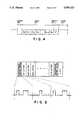
- FIG. 1(a)is a side view showing the external appearance of a motor vehicle
- FIG. 1(b)is a plan view showing the external appearance of a diagnosis unit, according to an embodiment of the present invention
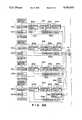
- FIGS. 2, 2A and 2Bare block diagrams showing a circuit construction of electronic control units of a diagnosis system according to the present invention
- FIGS. 3, 3A and 3Bare block diagrams showing functions of the control units and diagnosis unit of the diagnosis system according to the present invention.
- FIG. 4is an explanatory diagram showing a data format in a start-stop synchronous communication system of the diagnosis system according to the present invention
- FIG. 5is an explanatory diagram showing a data format in a clock synchronous communication system of the diagnosis system according to the present invention
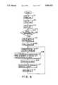
- FIG. 6is a flow chart showing an operational procedure of the diagnosis unit of the diagnosis system according to the present invention.
- FIG. 7is a flow chart showing an operational procedure of the electronic control unit of the diagnosis system according to the present invention.
- FIG. 8is a block diagram showing data communications between the electronic control units and the diagnosis unit in the diagnosis system according to the present invention.
- a motor vehicle 500provides various types of electronic control units (ECU) such as an engine control unit 501 for air-fuel ratio control or the like, a transmission control unit 502, a brake control unit 503 for anti-skid control, a cruise control unit 504 for driving in a constant speed by calculating various kind data necessary to driving vehicle.
- ECUelectronice control units
- Each ECU 501 to 504comprises central processing units (CPUs) 501a to 504a, random access memories (ROMs) 501b to 504b, read only memories (ROMs) 501c to 504c, non-volatile RAMs 501d to 504d, input interfaces 501g to 504g, and output interfaces 501e to 504e, respectively.
- the RAMs 501b to 504brespectively store various temporary parameters after various calculational operation.
- the non-volatile RAMs 501d to 504drespectively store various control maps.
- the ROMs 501c to 504crespectively store programs and fixed data.
- the ECU 501receives a plurality of signals, via the input interface 501g, from a coolant temperature sensor 9, an O 2 sensor 10, an intake manifold pressure sensor 11, an air conditioner switch SW1, a vehicle speed sensor 13, an accelerator switch SW5, a throttle position sensor 15, a neutral switch SW3, and an engine speed sensor 17.
- the CPU 501aprocesses data corresponding to the received signals so as to store in the RAM 501b. Then, the CPU 501a performs calculational operation in dependency on the stored data in the RAM 501b and in the control map of the non-volatile RAM 501d.
- the CPU 501agenerates various control signals in dependency on the calculated data and outputs the signals to a canister purge solenoid 19, an EGR (exhaust gas recirculation system) actuator 20, an idling control actuator 21, ignition coils 22, and fuel injectors 23 via the output interface 501e and a driver 501h thereby controlling the engine.
- EGRexhaust gas recirculation system
- the ECU 502receives a plurality of signals via the input interface 502g from the sensors 13, 15 and 17 and the switches SW3 and SW5, and outputs transmission signals (commands) to an automatic transmission (A/T) actuator 525 via the output interface 502e and a driver 502h thereby controlling an A/T (not shown) according to the running condition.
- A/Tautomatic transmission
- the ECU 503receives a plurality of signals from a brake switch SW6 and a wheel speed sensor 527 via the input interface 503g, and then calculates anti-skid operation according to the control program stored in the ROM 503c to produce a control signal.
- the ECU 503outputs the signal to a brake actuator 528 for an anti-skid braking system (ABS) via the output interface 503e and a driver 503h thereby controlling a skid of the wheels.
- ABSanti-skid braking system
- the ECU 504receives several signals via the input interface 504g from a speed set switch SW7 and the vehicle speed sensor 13, then controls a throttle actuator 530 to run the vehicle in constant speed via the output interface 504e and a driver 504h.
- the ECU 504receives several signals from the brake switch SW6, accelerator switch SW5, neutral switch SW3, deceleration switch SW8, and a resume switch SW9 via the input interface 504g, the ECU 504 removes the control of the constant speed running or reset a constant speed running after charging the speed of the vehicle.
- the ECUs 501 to 504are connected in parallel to a communication bus 24a comprising a transmission line 24b, a reception line 24c and a clock signal line 24d.
- the reception line 24cis connected in parallel to the input interfaces 501g to 504g, while the transmission line 24b is connected in parallel to the output interfaces 501e to 504e.
- the clock signal line 24dis connected in parallel to the input interface 504g of the ECU 504.
- the communication bus 24ais connected to an external connector 24 which is connected to an input/output connector 26 of a diagnosis unit 25 via an adapter harness 27.
- a diagnosis unit 25having a controller 28 and a power source circuit 29 therein and an indicator 30, a display 31 and a keyboard 32 on the surface thereof.
- the controller 28comprises a CPU 36, a RAM 37, a timer 38 such as a frequency counter and an input/output (I/O) interface 40 which are interconnected to each other, and a memory cartridge 34 externally connectable through a connector 33.
- the I/O interface 40is connected to the input/output connector 26 for transmitting a signal T x to the bus 24a, for receiving a signal R x from the bus 24a and for selectively outputting a clock signal CLK.
- the signal CLKis generated by frequency dividing of an output from a clock pulse oscillating element 42 provided in the timer 38 and generating a synchronous signal. In a clock synchronous communication system, data are transmitted and received in synchronization with the clock signal CLK.
- the keyboard 32is connected to an input side of the I/O interface 40, while the indicator 30 and display 31 are connected to an output side of the interface 40.
- the interface 40receives various control signals output from the output interfaces 501e to 504e and the output signals from various sensors and switches. A diagnosis for trouble is performed by displaying data in the display 31 after processing.
- Light emitting diodes (LEDs) D 1 to D 10 of the indicator 30are lit (or turned on or off) according to the signals of various switches so that it is possible to confirm operation of the switches.
- the cartridge 34Since the ECUs 501 to 504 have different diagnosis programs according to vehicle types, the cartridge 34 has a ROM 41 storing a diagnosis program for the ECUs 501 to 504 and fixed data therein and is capable of selectively connecting to the main body 25a.
- the power circuit 29 with the controller 28is connected to the power source BV of the vehicle 500 via an ON/OFF operation switch SW4.
- the ECUs 501 to 504comprise calculators 551a to 551d for arithmetically processing signals output from several sensors and switches, drivers 501h to 504h for outputting signals corresponding to actuators, data pickup circuits 552a to 552d, interpretation circuits 553a to 553d, reception circuits 554a to 554d, and transmission circuits 555a to 555d, respectively.
- the reception circuit 554d and transmission circuit 555dare interconnected to each other through synchronization circuit 556.
- the reception circuits 554a to 554dare connected in parallel to the reception line 24c of the communication bus 24a, respectively, while the transmission circuits 555a to 555d are connected in parallel to the transmission line 24b of the bus 24a, respectively.
- the synchronization circuit 556is connected to the clock signal line 24d of the bus 24a and synchronizes the reception circuit 554d and the transmission circuit 555d of the ECU 504 with the clock signal CLK transmitted together with the data thereby transmitting and receiving the data.
- the diagnosis unit 25comprises communication circuits 56a and 56b, a data calculation circuit 57, a keyboard interpretation circuit 58, a display drive circuit 59, the keyboard 32, and the display 31.
- the communication circuit 56ahas a transmission line and reception line connected to the input/output connector 26, while the communication circuit 56b has a transmission line, a reception line and a clock signal line connected to the input/output connector 26.
- a communication between the ECUs 501 to 503 and the diagnosis unit 25is performed by the start-stop synchronous system through the communication circuit 56a, while a communication between the ECU 504 and the diagnosis unit 25 is performed by the clock synchronous system through the communication circuit 56b.
- the start-stop synchronous systemhas a data format where a start bit added to every one letter, data of the letter constructed by, for example, eight bits, an error detection bit such as a parity bit, and a stop bit are successively transmitted.
- the communication circuit 56areceives data in every synchronous letter.
- the clock synchronous systemhas a data format, as shown in FIG. 5, in which a transmission control letter showing a start of data is firstly transmitted for every one group of a letter line, and then the letter line having a first to n-th letters is successively transmitted. After transmitting the last transmission control letter indicating an end of data, an error detection bit such as a CRC check is lastly transmitted.
- the data and synchronous signals(clock signals) are transmitted at the same time with respective line, and the communication circuit 56b receives the data in synchronous with the clock signals.
- the reception circuits 554a to 554dreceive various order signals from the diagnosis unit 25, and the interpretation circuits 553a to 553d interpret the contents of the various order signals, respectively.
- the interpretation circuits 553a to 553dinstruct a pickup of the predetermined data to the data pickup circuits 552a to 552d according to the interpreted contents.
- the data pickup circuits 552a to 552dpick up various data calculated by the calculator 551a to 551d or the fixed data stored in the ROM 501c to 504c thereby transmitting the data to the diagnosis unit 25 via the transmission circuits 555a to 555d.
- the interpretation circuit 58interprets the diagnosis mode supplied from the keyboard 32 to determine the control unit corresponding to the diagnosis mode from any of the ECU 501 to 504 thereby selecting the communication circuit 56a or 56b responsive to the communication type thereof.
- the ECUs 501 to 503receive various demand signals from the communication circuit 56a by the start-stop synchronous system, while the ECU 504 receives the various demand signals from the communication circuit 56b by the clock synchronous system.
- the communication circuit 56a or 56breceives the data transmitted from one of the ECUs 501 to 504 responsive to the various demand signals, the data are calculated by the data calculation circuit 57 thereby displaying in the display 31 through the display drive circuit 59.
- the input/output connector 26 of the diagnosis unit 25is connected to the external connector 24 of the vehicle 500 directly or through the adapter harness 27.
- the diagnosis unit 25has the power turned on (step 101), and initialized (step 102). Then, the communication circuit 56a is automatically selected and outputs a unit identification code demand signal to the ECU 501 (step 103). Namely, as the unit identification code is stored in the ROM 501c of the ECU 501 in advance and the ECU 501 has the start-stop synchronous communication system, the communication circuit 56a is selected.
- the demand signal from the diagnosis unit 25is transmitted from the transmission circuit 56a by the start-stop synchronous system, as shown in FIG. 8, to every ECUs 501 to 503.
- the demand signalcomprises the control unit specifying code and the data demand code in order.
- the unit identification code demand signalis transmitted from the diagnosis unit 25 to every ECU 501 to 503 in order of an engine control unit specifying code and a unit identification code demand code.
- the demand signal from the diagnosis unit 25is received by every ECU 501 to 503 having the start-stop synchronous system.
- the ECU 504 having the clock synchronous systemdoes not receive the demand signal because the clock signal CLK is not transmitted.
- the ECU 501 to 503are interrupted to stop executing task, and operation is advanced to step 201 as shown in FIG. 7.
- step 201the interpretation circuits 553a to 553c of the ECUs 501 to 503 determine whether or not transmission flags are "1", respectively. At the first time of the transmission demand, as the transmission flag is "0", operation is advanced to step 202.
- step 202the interpretation circuits 553a to 553c discriminate whether or not the own transmission demand to the respective ECU 501 to 503 are transmitted.
- the specifying codeis the engine control unit specifying code
- only operation of the ECU 501is advanced from the step 202 to step 203, and operation of the ECU 502 and 503 is out of the routine of the step 202 to stop the interruption.
- the ECU 502 and 503have the flag of "0" and open the transmission line 24b of the bus 24a to the diagnosis unit 25 by the transmission circuits 555b and 555c.
- the ECU 501sets the transmission flag "1" in step 203 to output the transmission start signal from the interpretation circuit 553a to the transmission circuit 555a.
- operationis advanced to step 204.
- step 204the interpretation circuit 553a requires to the data pickup circuit 552a to read out the data of the unit identification code stored in the ROM 501c in advance.
- the code datais transmitted to the diagnosis unit 25 via the transmission circuit 555a.
- the interpretation circuit 553adetermines whether the demand to end the transmission is performed by the predetermined code input from the diagnosis unit 25 or by turning off the power switch SW4 of the diagnosis unit 25.
- the transmission flagis "0" (namely, clarified)
- the interpretation circuit 553aoutputs the transmission end demand signal to the transmission circuit 555a.
- the transmission circuit 555aopens the transmission line 24b to the diagnosis unit 25 to end the transmission and the interruption.
- the transmission flagis not clarified and the interruption in the blank time of the ECU 501 continues thereby maintaining the transmission of the unit identification code.
- step 104the diagnosis unit 25 determines whether or not the data such as the unit identification code is received from the ECU 501. When the unit 25 confirms the reception of the data, operation is advanced to step 105. If the data are not received, operation returns to step 104 and the judgement is repeated.
- step 105the CPU 36 discriminates the type of the control unit and stores the received unit identification code in the predetermined address of the RAM 37.
- step 106a table corresponding to the identification code is selected from a plurality of tables stored in the ROM 41 of the memory cartridge 34. As a result, the table corresponding to the control units of the vehicle is specified, after that, the diagnosis is performed according to the program stored in the table.
- step 107for example, when the coolant temperature data in the ECU 501 are diagnosed in dependency on data output from the coolant temperature sensor 9, the corresponding mode is input by key operation of the keyboard 32, for example, input of "F ⁇ 0 ⁇ 7 ⁇ ENT". Then, the CPU 36 of the diagnosis unit 25 reads out the mode to temporarily store it in the predetermined address of the RAM 37. After the diagnosis mode stored in the RAM 37 is read out, the keyboard interpretation circuit 58 interprets the contents of the diagnosis mode to select the program corresponding to the diagnosis mode. At the same time, the communication circuits 56a or 56b corresponding to the diagnosis mode is respectively selected. In this case of the embodiment, the communication circuit 56a for the start-stop synchronous system is selected because of the communication with the ECU 501. The fixed data such as an abbreviation and a unit corresponding to the diagnosis mode are read out from the ROM 41 to store them in the predetermined address of the RAM 37. Then, operation is advanced to step 108.
- step 108the data communication circuit 56a outputs the transmission demand signal T x of the data, for example, the coolant temperature data in the ECU 501, corresponding to the diagnosis mode interpreted by the circuit 58 to the communication bus 24a connecting every ECU 501 to 504 of the vehicle 500.
- the transmission demand signal for the coolant temperature data in the ECU 501is transmitted to every ECU 501 to 503 via the transmission bus 24a in the order of the engine control unit specifying code and the coolant temperature data demand code by the start-stop synchronous system.
- the interruption programstarts by the data transmission demand signal from the diagnosis unit 25. Since the ECUs 502 and 503 have the transmission flag "0" as aforementioned, operation is advanced from step 201 to 202. In step 202, since the control unit specifying code is the engine control unit specifying code, the program leaves from step 202 to end the interruption program.
- step 204since the ECU 501 is in the condition of transmitting the data of the unit identification code and keeps the transmission flag "1", operation is advanced from step 201 to step 204 so that the interpretation circuit 553a decodes that the data transmission demand signal from the diagnosis unit 25 is for the coolant temperature data. Indicating signal to pickup the coolant temperature data is output to the data pickup circuit 552a. Then, the data pick up circuit 552a stops data pickup operation of the unit identification code and picks up the coolant temperature data, so that transmitting the coolant temperature data to the diagnosis unit 25 by the transmission circuit 555a.
- step 109 as shown in FIG. 6the data communication circuit 56a receives the data signal R x output from the ECU 501.
- step 110the data from the ECU 501 changes to the physical quantity by the calculation in the data calculation circuit 57. Namely, binary data are changed into decimal numerical data.
- the numerical data and fixed datasuch as the abbreviation and unit stored in the RAM 37 in step 107 are output to the display drive circuit 59.
- step 111 shown in FIG. 6the display drive circuit 59 outputs a display signal to the display 31 to indicate the numerical data, abbreviation, diagnosis mode number (function number input by key operation), and unit on the screen of the display 31.
- diagnosis mode for the coolant temperature sensoras shown in the screen of the display 31 of FIG. 1(b), there are indicated an abbreviation "TW" of the coolant temperature, a function number "F07”, a numerical value "+14" of the coolant temperature data, and an unit "deg C”. Operation then returns to step 107 and the diagnosis system awaits the next input from the keyboard.
- demanded dataare signals outputting to the throttle actuator 530 in the cruise control unit (the ECU 504) as other control unit without the engine control unit (the ECU 501)
- the interpretation circuit 58decodes the contents of the mode input by key operation (for instance, "F ⁇ 2 ⁇ 4 ⁇ ENT") of the keyboard 32 in the aforementioned manner.
- the communication circuit 56b of the clock synchronous system corresponding to the ECU 504is selected after the presently selected communication circuit 56a of the start-stop synchronous system output the transmission end demand signal.
- step 108the data transmission demand signal for demanding output data to the throttle actuator 530 is output from the communication circuit 56b to the ECU 504 in synchronization with the clock signal CLK corresponding to the diagnosis mode decoded by the interpretation circuit 58.
- the clock signal CLKis transmitted at a speed that the ECU 504 is capable of certainly receiving the demand signal.
- the data transmission demand signalis output to the ECU 504 in the order of the cruise control unit specifying code and the throttle actuator output data demand code.
- step 206the indicating signal to end the transmission is output from the interpretation circuit 553a of the ECU 501 to the communication circuit 555a by means that the transmission flag is set to "0", namely clarified, then the transmission line 24b to the diagnosis unit 25 is opened.
- the transmission of the coolant temperature data from the ECU 501 to the diagnosis unit 25is over, in dependency on the end of pickup of the coolant temperature data by the data pickup circuit 552a.
- the ECU 504receives the data by the reception circuit 554d in synchronization with the clock signal, and starts the interruption.
- operationis advanced from step 201 to step 202 as shown in FIG. 7, then to the step 203 by the cruise control unit specifying code.
- step 203the transmission flag of the ECU 504 is set to "1", and the transmission start signal is output from the interpretation circuit 553d of the ECU 504 to the transmission circuit 555d to communicate the transmission line 24b to the diagnosis unit 25, and then operation is advanced to step 204.
- step 204the interpretation circuit 553d of the ECU 504 requires the data pickup circuit 552d to read out a speed set switch data.
- the pickup circuit 552dpicks up the output data to the throttle actuator output data to transmit the data from the transmission circuit 555d to the diagnosis unit 25 in synchronization with the clock signal.
- the diagnosis unit 25receives the output data to the throttle actuator by the communication circuit 56b in step 109, and calculates and changes the physical quantity from the binary data to the decimal numerical data by the data calculation circuit 57 in step 110.
- the changed dataare output through the display drive circuit 59 to the display 31 to indicate the numerical value of the output data to the throttle actuator.
- the communication circuit 56a or 56boutputs the transmission end demand signal.
- operation of ECU 504is advanced from step 205 to step 206, then the transmission flag is clarified to "0".
- the data transmitting ECUsuch as the aforementioned ECU 504 stops the data pickup operation in the pickup circuit 552d in dependency on the indicating signal to end the transmission from the interpretation circuit 553d.
- the circuit 553doutputs the end signal to the transmission circuit 555d to open the transmission line 24b to the diagnosis unit 25, and then the data transmission of the ECU 504 is over.
- the above-mentioned transmission end demand signalmay be produced by inputting the predetermined transmission end demand code from the keyboard 32.
- the engine control unit such as the ECU 501, the transmission control unit such as the ECU 502, the brake control unit such as the ECU 503, and the cruise control unit such as the ECU 504have different communication systems, respectively, such as the start-stop synchronous system and the clock synchronous system corresponding to the difference of the processing ability, it is possible to diagnose the troubles corresponding to each communication system of the ECUs only by the connection between one external connector 24 and the diagnosis unit 25, and by input operation of the diagnosis mode through the keyboard 32. Therefore, it is possible to systematically diagnose the troubles common to the several units.
- the diagnosis systemcomprises a plurality of electronic control units having different communication systems and a communication bus for interconnecting between the control units and the diagnosis unit in parallel, and one external connector provided to the bus, so that it is possible to diagnose the troubles of the vehicle by only connecting the external connector to the diagnosis unit without a plurality of communication buses to every communication systems. Namely, it is unnecessary to attach and remove the connector at every change of the communication systems, thereby facilitating diagnosis the control units having different communication systems. Accordingly, workability is extremely improved and it is easy to diagnose the troubles related to control units having different communication systems.
Landscapes
- Engineering & Computer Science (AREA)
- Physics & Mathematics (AREA)
- General Physics & Mathematics (AREA)
- Computer Hardware Design (AREA)
- Microelectronics & Electronic Packaging (AREA)
- Chemical & Material Sciences (AREA)
- Combustion & Propulsion (AREA)
- Combined Controls Of Internal Combustion Engines (AREA)
- Testing And Monitoring For Control Systems (AREA)
- Testing Electric Properties And Detecting Electric Faults (AREA)
- Test And Diagnosis Of Digital Computers (AREA)
Abstract
Description
Claims (7)
Applications Claiming Priority (2)
| Application Number | Priority Date | Filing Date | Title |
|---|---|---|---|
| JP63-266308 | 1988-10-21 | ||
| JP63266308AJPH0776737B2 (en) | 1988-10-21 | 1988-10-21 | Vehicle diagnostic system |
Publications (1)
| Publication Number | Publication Date |
|---|---|
| US5056023Atrue US5056023A (en) | 1991-10-08 |
Family
ID=17429125
Family Applications (1)
| Application Number | Title | Priority Date | Filing Date |
|---|---|---|---|
| US07/423,779Expired - LifetimeUS5056023A (en) | 1988-10-21 | 1989-10-18 | Diagnosis system for motor vehicle |
Country Status (4)
| Country | Link |
|---|---|
| US (1) | US5056023A (en) |
| JP (1) | JPH0776737B2 (en) |
| DE (1) | DE3935144A1 (en) |
| GB (1) | GB2226160B (en) |
Cited By (65)
| Publication number | Priority date | Publication date | Assignee | Title |
|---|---|---|---|---|
| WO1992014216A1 (en)* | 1991-01-30 | 1992-08-20 | Edge Diagnostic Systems | Interactive diagnostic system for an automotive vehicle, and method |
| WO1993004353A1 (en)* | 1991-08-12 | 1993-03-04 | Crane Harold E | Interactive dynamic realtime management system for powered vehicles |
| US5200911A (en)* | 1989-05-19 | 1993-04-06 | Nissan Motor Company, Limited | Apparatus for detecting failure occurring in control system for driving load |
| US5229942A (en)* | 1990-11-13 | 1993-07-20 | Bear Automotive Service Equipment Company | Control system for remote power up |
| US5345383A (en)* | 1992-09-16 | 1994-09-06 | Caterpillar Inc. | Method and apparatus for selectively monitoring input |
| US5418721A (en)* | 1993-02-23 | 1995-05-23 | Yazaki Corporation | Control device for transmission of supervisory control data in vehicle |
| US5491418A (en)* | 1994-10-27 | 1996-02-13 | General Motors Corporation | Automotive diagnostic communications interface |
| US5541840A (en)* | 1993-06-25 | 1996-07-30 | Chrysler Corporation | Hand held automotive diagnostic service tool |
| US5555498A (en)* | 1994-03-18 | 1996-09-10 | Chrysler Corporation | Circuit and method for interfacing vehicle controller and diagnostic test instrument |
| US5553488A (en)* | 1993-07-30 | 1996-09-10 | Toyota Jidosha Kabushiki Kaisha | Diagnosis apparatus for vehicle control system |
| US5565856A (en)* | 1993-10-05 | 1996-10-15 | Nippondenso Co., Ltd. | Abnormality detecting device for vehicle communication system and method of using same |
| US5574645A (en)* | 1995-02-28 | 1996-11-12 | Snap-On Technologies, Inc. | Manifold absolute pressure sensor emulator |
| US5631831A (en)* | 1993-02-26 | 1997-05-20 | Spx Corporation | Diagnosis method for vehicle systems |
| WO1997013064A3 (en)* | 1995-10-03 | 1997-06-05 | Volvo Ab | Diagnostic system particularly for an engine management system |
| US5673668A (en)* | 1996-08-05 | 1997-10-07 | Ford Global Technologies, Inc. | Method and apparatus for electronic throttle monitoring |
| US5705743A (en)* | 1996-11-13 | 1998-01-06 | Ford Global Technologies, Inc. | Method for identifying parameter identifiers of a motor vehicle |
| US5737711A (en)* | 1994-11-09 | 1998-04-07 | Fuji Jukogyo Kabuishiki Kaisha | Diagnosis system for motor vehicle |
| US5771474A (en)* | 1994-01-04 | 1998-06-23 | Robertbosch Gmbh | Method for testing electronic control devices |
| US5836156A (en)* | 1994-09-16 | 1998-11-17 | Hitachi, Ltd. | Driving device of sensors and actuators |
| US5899947A (en)* | 1997-06-30 | 1999-05-04 | Daimlerchrysler Corporation | Current check module for hand-held vehicle tester |
| US6157877A (en)* | 1995-09-05 | 2000-12-05 | Sun Electric U.K. Limited | Apparatus and method for testing automotive electronic control units and batteries and related equipment |
| US6236917B1 (en) | 1999-12-21 | 2001-05-22 | Spx Corporation | Open architecture diagnostic tool |
| US6311162B1 (en) | 1998-07-25 | 2001-10-30 | Ernst F. Reichwein | Interactive symptomatic recording system and methods |
| US20020077779A1 (en)* | 2000-10-17 | 2002-06-20 | Spx Corporation | Apparatus and method for displaying diagnostic values |
| US20020077781A1 (en)* | 2000-10-17 | 2002-06-20 | Spx Corporation | Data monitoring and display method and apparatus |
| US20030009270A1 (en)* | 1995-06-07 | 2003-01-09 | Breed David S. | Telematics system for vehicle diagnostics |
| US6526340B1 (en) | 1999-12-21 | 2003-02-25 | Spx Corporation | Multi-vehicle communication interface |
| US6577934B2 (en)* | 2001-02-22 | 2003-06-10 | Mitsubishi Denki Kabushiki Kaisha | Failure diagnosis apparatus |
| US6604032B1 (en)* | 1997-04-01 | 2003-08-05 | Volvo Personvagnar Ab | Diagnostic system in an engine management system |
| US6606028B1 (en)* | 1999-04-23 | 2003-08-12 | Pittway Corporation | Apparatus and method for supervision |
| US6654702B2 (en)* | 2000-07-26 | 2003-11-25 | Sumitomo Wiring Systems, Ltd. | Method of checking vehicle mounted electronic units |
| US6662087B1 (en) | 2000-01-03 | 2003-12-09 | Spx Corporation | Backward compatible diagnostic tool |
| US6697763B1 (en) | 1999-12-07 | 2004-02-24 | Pei Electronics, Inc. | Measurement module and system for monitoring the status of armored vehicle electronic components |
| WO2004074048A1 (en)* | 2003-02-21 | 2004-09-02 | Audi Ag | Device and method for central on-board diagnosis for motor vehicles |
| US20040204816A1 (en)* | 2001-12-21 | 2004-10-14 | Normand Dery | Remote starting system for a vehicle |
| US20040230320A1 (en)* | 2003-03-05 | 2004-11-18 | Yazaki Corporation | Electronic connector and auxiliary module |
| US6874680B1 (en) | 2000-10-17 | 2005-04-05 | Spx Corporation | Remote updating method and apparatus |
| WO2005034047A1 (en)* | 2003-10-03 | 2005-04-14 | Snap-On Technologies, Inc. | System and method for diagnosing an automotive vehicle |
| US20050125117A1 (en)* | 1995-06-07 | 2005-06-09 | Breed David S. | Vehicular information and monitoring system and methods |
| US20050137762A1 (en)* | 1997-10-28 | 2005-06-23 | Snap-On Technologies, Inc. | System for dynamic diagnosis of apparatus operating conditions |
| US6937926B2 (en)* | 2002-09-27 | 2005-08-30 | Spx Corporation | Multi-application data display |
| US7050892B1 (en) | 1999-12-21 | 2006-05-23 | Spx Corporation | Diagnostic tool security key |
| US20060184295A1 (en)* | 2005-02-17 | 2006-08-17 | Steve Hawkins | On-board datalogger apparatus and service methods for use with vehicles |
| US7103460B1 (en) | 1994-05-09 | 2006-09-05 | Automotive Technologies International, Inc. | System and method for vehicle diagnostics |
| US20060242537A1 (en)* | 2005-03-30 | 2006-10-26 | Dang Lich X | Error detection in a logic device without performance impact |
| US20070005202A1 (en)* | 1995-06-07 | 2007-01-04 | Automotive Technologies International, Inc. | Remote Vehicle Diagnostic Management |
| US20070233340A1 (en)* | 2006-03-31 | 2007-10-04 | Kurt Raichle | Simultaneous vehicle protocol communication apparatus and method |
| US20070271014A1 (en)* | 1995-06-07 | 2007-11-22 | Automotive Technologies International, Inc. | Vehicle Diagnostic and Prognostic Methods and Systems |
| US20080284575A1 (en)* | 1995-06-07 | 2008-11-20 | Automotive Technologies International, Inc. | Vehicle Diagnostic Techniques |
| US20090045626A1 (en)* | 2007-08-17 | 2009-02-19 | Honda Motor Co., Ltd. | Cogeneration system |
| US20090241651A1 (en)* | 2008-03-27 | 2009-10-01 | International Truck Intellectual Property Company Llc | Electrical system testing using a wireless-controlled load bank |
| US20090292434A1 (en)* | 2006-07-14 | 2009-11-26 | Blaeser Markus | Method for Synchronising Components of a Motor Vehicle Brake System and Electronic Brake Control System |
| US7630802B2 (en) | 1995-06-07 | 2009-12-08 | Automotive Technologies International, Inc. | Information management and monitoring system and method |
| US20100280813A1 (en)* | 2009-04-30 | 2010-11-04 | Gm Global Technology Operations, Inc. | Portable usb power mode simulator tool |
| US8239170B2 (en) | 2000-03-09 | 2012-08-07 | Smartsignal Corporation | Complex signal decomposition and modeling |
| US8275577B2 (en) | 2006-09-19 | 2012-09-25 | Smartsignal Corporation | Kernel-based method for detecting boiler tube leaks |
| US8311774B2 (en) | 2006-12-15 | 2012-11-13 | Smartsignal Corporation | Robust distance measures for on-line monitoring |
| US20130325323A1 (en) | 1998-10-22 | 2013-12-05 | American Vehicular Sciences | Vehicle software upgrade techniques |
| US8620853B2 (en) | 2011-07-19 | 2013-12-31 | Smartsignal Corporation | Monitoring method using kernel regression modeling with pattern sequences |
| US8660980B2 (en) | 2011-07-19 | 2014-02-25 | Smartsignal Corporation | Monitoring system using kernel regression modeling with pattern sequences |
| CN105116871A (en)* | 2015-07-10 | 2015-12-02 | 深圳市元征科技股份有限公司 | Signal transmission circuit and communication device of automobile diagnosis system |
| US9250625B2 (en) | 2011-07-19 | 2016-02-02 | Ge Intelligent Platforms, Inc. | System of sequential kernel regression modeling for forecasting and prognostics |
| US9256224B2 (en) | 2011-07-19 | 2016-02-09 | GE Intelligent Platforms, Inc | Method of sequential kernel regression modeling for forecasting and prognostics |
| US9443358B2 (en) | 1995-06-07 | 2016-09-13 | Automotive Vehicular Sciences LLC | Vehicle software upgrade techniques |
| CN106644508A (en)* | 2016-12-09 | 2017-05-10 | 江铃汽车股份有限公司 | Reliability performance test method and device for automobile start stop system |
Families Citing this family (13)
| Publication number | Priority date | Publication date | Assignee | Title |
|---|---|---|---|---|
| DE4036241A1 (en)* | 1990-11-14 | 1992-05-21 | Joerg Golombek | Measuring and evaluating physical data of vehicle model - using microprocessor with program and data memory, connected via A=D converters to sensors of different parameters |
| DE4210841C2 (en)* | 1991-04-12 | 1997-04-30 | Siemens Ag | Interface circuit for transmitting data between a control device to be tested and a diagnostic device for motor vehicles |
| DE4210526A1 (en)* | 1991-04-25 | 1992-10-29 | Abb Patent Gmbh | Data transfer arrangement between measurement acquisition and processing units - has auxiliary unit mechanically joined to acquisition unit and coupled to it which passes data to processing unit |
| JPH0526662U (en)* | 1991-09-25 | 1993-04-06 | スズキ株式会社 | Electronic control unit for vehicle |
| AU668370B2 (en)* | 1991-12-20 | 1996-05-02 | Snap-On Technologies, Inc. | Automotive service equipment expert system |
| CA2086449C (en)* | 1992-01-06 | 2000-03-07 | Steven W. Rogers | Computer interface board for electronic automotive vehicle service |
| DE4437334C1 (en)* | 1994-10-19 | 1996-04-04 | Bosch Gmbh Robert | Service-friendly immobilizer |
| DE29513552U1 (en)* | 1995-08-23 | 1995-10-05 | Kugel, Gerhard, 76307 Karlsbad | Measuring device |
| DE10348297B4 (en)* | 2003-10-17 | 2010-05-27 | Audi Ag | Test device for control units of a motor vehicle and method for testing control units of a motor vehicle |
| JP4661438B2 (en)* | 2005-08-04 | 2011-03-30 | 株式会社デンソー | Vehicle communication system |
| JP2009264770A (en)* | 2008-04-22 | 2009-11-12 | Sii Ido Tsushin Kk | Vehicle diagnostic system, vehicle diagnostic terminal, information server device, and vehicle diagnostic method |
| CN103064399B (en)* | 2011-10-20 | 2017-03-15 | 上海通用汽车有限公司 | Fault simulation analytical equipment for vehicle diagnostics |
| JP6915512B2 (en)* | 2017-11-28 | 2021-08-04 | トヨタ自動車株式会社 | Server device, faulty vehicle estimation method and faulty vehicle estimation program |
Citations (3)
| Publication number | Priority date | Publication date | Assignee | Title |
|---|---|---|---|---|
| US4894781A (en)* | 1986-10-02 | 1990-01-16 | Nippondenso Co., Ltd. | Communication control system |
| US4899338A (en)* | 1988-12-15 | 1990-02-06 | Chrysler Motors Corporation | Electrical device command system, single wire bus and smart octal controller arrangement therefor |
| US4924391A (en)* | 1987-02-27 | 1990-05-08 | Mitsubishi Denki Kabushiki Kaisha | Trouble-diagnosable multifunction testing apparatus |
Family Cites Families (6)
| Publication number | Priority date | Publication date | Assignee | Title |
|---|---|---|---|---|
| GB1360000A (en)* | 1970-11-13 | 1974-07-17 | British Railways Board | Signalling systems |
| JPS5812848A (en)* | 1981-07-16 | 1983-01-25 | Nissan Motor Co Ltd | Vehicle diagnosing apparatus |
| DE3540599A1 (en)* | 1985-11-15 | 1987-05-21 | Porsche Ag | DIAGNOSTIC SYSTEM FOR A MOTOR VEHICLE |
| JPH07122659B2 (en)* | 1986-08-18 | 1995-12-25 | 三菱電機株式会社 | Failure diagnosis system for automobile electronic devices |
| JPS6348477A (en)* | 1986-08-18 | 1988-03-01 | Mitsubishi Electric Corp | Fault diagnosing system for electronic equipment for automobile |
| JPH0752141B2 (en)* | 1987-12-11 | 1995-06-05 | 富士重工業株式会社 | Vehicle diagnostic system |
- 1988
- 1988-10-21JPJP63266308Apatent/JPH0776737B2/ennot_activeExpired - Fee Related
- 1989
- 1989-10-18USUS07/423,779patent/US5056023A/ennot_activeExpired - Lifetime
- 1989-10-20GBGB8923668Apatent/GB2226160B/ennot_activeExpired - Lifetime
- 1989-10-21DEDE3935144Apatent/DE3935144A1/enactiveGranted
Patent Citations (3)
| Publication number | Priority date | Publication date | Assignee | Title |
|---|---|---|---|---|
| US4894781A (en)* | 1986-10-02 | 1990-01-16 | Nippondenso Co., Ltd. | Communication control system |
| US4924391A (en)* | 1987-02-27 | 1990-05-08 | Mitsubishi Denki Kabushiki Kaisha | Trouble-diagnosable multifunction testing apparatus |
| US4899338A (en)* | 1988-12-15 | 1990-02-06 | Chrysler Motors Corporation | Electrical device command system, single wire bus and smart octal controller arrangement therefor |
Cited By (96)
| Publication number | Priority date | Publication date | Assignee | Title |
|---|---|---|---|---|
| US5200911A (en)* | 1989-05-19 | 1993-04-06 | Nissan Motor Company, Limited | Apparatus for detecting failure occurring in control system for driving load |
| US5229942A (en)* | 1990-11-13 | 1993-07-20 | Bear Automotive Service Equipment Company | Control system for remote power up |
| WO1992014216A1 (en)* | 1991-01-30 | 1992-08-20 | Edge Diagnostic Systems | Interactive diagnostic system for an automotive vehicle, and method |
| WO1993004353A1 (en)* | 1991-08-12 | 1993-03-04 | Crane Harold E | Interactive dynamic realtime management system for powered vehicles |
| US5257190A (en)* | 1991-08-12 | 1993-10-26 | Crane Harold E | Interactive dynamic realtime management system for powered vehicles |
| US5450321A (en)* | 1991-08-12 | 1995-09-12 | Crane; Harold E. | Interactive dynamic realtime management system for powered vehicles |
| US5345383A (en)* | 1992-09-16 | 1994-09-06 | Caterpillar Inc. | Method and apparatus for selectively monitoring input |
| US5418721A (en)* | 1993-02-23 | 1995-05-23 | Yazaki Corporation | Control device for transmission of supervisory control data in vehicle |
| US5631831A (en)* | 1993-02-26 | 1997-05-20 | Spx Corporation | Diagnosis method for vehicle systems |
| US6181992B1 (en) | 1993-06-25 | 2001-01-30 | Chrysler Corporation | Automotive diagnostic service tool with hand held tool and master controller |
| US5541840A (en)* | 1993-06-25 | 1996-07-30 | Chrysler Corporation | Hand held automotive diagnostic service tool |
| US5553488A (en)* | 1993-07-30 | 1996-09-10 | Toyota Jidosha Kabushiki Kaisha | Diagnosis apparatus for vehicle control system |
| US5565856A (en)* | 1993-10-05 | 1996-10-15 | Nippondenso Co., Ltd. | Abnormality detecting device for vehicle communication system and method of using same |
| US5771474A (en)* | 1994-01-04 | 1998-06-23 | Robertbosch Gmbh | Method for testing electronic control devices |
| US5555498A (en)* | 1994-03-18 | 1996-09-10 | Chrysler Corporation | Circuit and method for interfacing vehicle controller and diagnostic test instrument |
| US7103460B1 (en) | 1994-05-09 | 2006-09-05 | Automotive Technologies International, Inc. | System and method for vehicle diagnostics |
| US5836156A (en)* | 1994-09-16 | 1998-11-17 | Hitachi, Ltd. | Driving device of sensors and actuators |
| US5491418A (en)* | 1994-10-27 | 1996-02-13 | General Motors Corporation | Automotive diagnostic communications interface |
| US5737711A (en)* | 1994-11-09 | 1998-04-07 | Fuji Jukogyo Kabuishiki Kaisha | Diagnosis system for motor vehicle |
| US5574645A (en)* | 1995-02-28 | 1996-11-12 | Snap-On Technologies, Inc. | Manifold absolute pressure sensor emulator |
| US20070271014A1 (en)* | 1995-06-07 | 2007-11-22 | Automotive Technologies International, Inc. | Vehicle Diagnostic and Prognostic Methods and Systems |
| US7650210B2 (en) | 1995-06-07 | 2010-01-19 | Automotive Technologies International, Inc. | Remote vehicle diagnostic management |
| US6738697B2 (en)* | 1995-06-07 | 2004-05-18 | Automotive Technologies International Inc. | Telematics system for vehicle diagnostics |
| US7082359B2 (en) | 1995-06-07 | 2006-07-25 | Automotive Technologies International, Inc. | Vehicular information and monitoring system and methods |
| US20070005202A1 (en)* | 1995-06-07 | 2007-01-04 | Automotive Technologies International, Inc. | Remote Vehicle Diagnostic Management |
| US20050125117A1 (en)* | 1995-06-07 | 2005-06-09 | Breed David S. | Vehicular information and monitoring system and methods |
| US9443358B2 (en) | 1995-06-07 | 2016-09-13 | Automotive Vehicular Sciences LLC | Vehicle software upgrade techniques |
| US20080284575A1 (en)* | 1995-06-07 | 2008-11-20 | Automotive Technologies International, Inc. | Vehicle Diagnostic Techniques |
| US8024084B2 (en) | 1995-06-07 | 2011-09-20 | Automotive Technologies International, Inc. | Vehicle diagnostic techniques |
| US8019501B2 (en) | 1995-06-07 | 2011-09-13 | Automotive Technologies International, Inc. | Vehicle diagnostic and prognostic methods and systems |
| US20030009270A1 (en)* | 1995-06-07 | 2003-01-09 | Breed David S. | Telematics system for vehicle diagnostics |
| US7630802B2 (en) | 1995-06-07 | 2009-12-08 | Automotive Technologies International, Inc. | Information management and monitoring system and method |
| US6157877A (en)* | 1995-09-05 | 2000-12-05 | Sun Electric U.K. Limited | Apparatus and method for testing automotive electronic control units and batteries and related equipment |
| WO1997013064A3 (en)* | 1995-10-03 | 1997-06-05 | Volvo Ab | Diagnostic system particularly for an engine management system |
| US5673668A (en)* | 1996-08-05 | 1997-10-07 | Ford Global Technologies, Inc. | Method and apparatus for electronic throttle monitoring |
| US5705743A (en)* | 1996-11-13 | 1998-01-06 | Ford Global Technologies, Inc. | Method for identifying parameter identifiers of a motor vehicle |
| US6604032B1 (en)* | 1997-04-01 | 2003-08-05 | Volvo Personvagnar Ab | Diagnostic system in an engine management system |
| US5899947A (en)* | 1997-06-30 | 1999-05-04 | Daimlerchrysler Corporation | Current check module for hand-held vehicle tester |
| US8620511B2 (en)* | 1997-10-28 | 2013-12-31 | Snap-On Incorporated | System for dynamic diagnosis of apparatus operating conditions |
| US9562830B2 (en) | 1997-10-28 | 2017-02-07 | Snap-On Incorporated | System for dynamic diagnosis of apparatus operating conditions |
| US20050137762A1 (en)* | 1997-10-28 | 2005-06-23 | Snap-On Technologies, Inc. | System for dynamic diagnosis of apparatus operating conditions |
| US6311162B1 (en) | 1998-07-25 | 2001-10-30 | Ernst F. Reichwein | Interactive symptomatic recording system and methods |
| US20070276560A1 (en)* | 1998-07-25 | 2007-11-29 | Reichwein Ernst F | Interactive symptomatic recording system and method utilizing symptomatic memory |
| US20020040328A1 (en)* | 1998-07-25 | 2002-04-04 | Reichwein Ernst F. | Interactive symptomatic recording system and method utilizing symptomatic memory |
| US7254550B2 (en) | 1998-07-25 | 2007-08-07 | Reichwein & White Enterprises | Interactive symptomatic recording system and method utilizing symptomatic memory |
| US20010053983A1 (en)* | 1998-07-25 | 2001-12-20 | Reichwein Ernst F. | Interactive symptomatic recording system and methods |
| US20130325323A1 (en) | 1998-10-22 | 2013-12-05 | American Vehicular Sciences | Vehicle software upgrade techniques |
| US10240935B2 (en) | 1998-10-22 | 2019-03-26 | American Vehicular Sciences Llc | Vehicle software upgrade techniques |
| US6606028B1 (en)* | 1999-04-23 | 2003-08-12 | Pittway Corporation | Apparatus and method for supervision |
| US6697763B1 (en) | 1999-12-07 | 2004-02-24 | Pei Electronics, Inc. | Measurement module and system for monitoring the status of armored vehicle electronic components |
| US7050892B1 (en) | 1999-12-21 | 2006-05-23 | Spx Corporation | Diagnostic tool security key |
| US6236917B1 (en) | 1999-12-21 | 2001-05-22 | Spx Corporation | Open architecture diagnostic tool |
| US6526340B1 (en) | 1999-12-21 | 2003-02-25 | Spx Corporation | Multi-vehicle communication interface |
| US6662087B1 (en) | 2000-01-03 | 2003-12-09 | Spx Corporation | Backward compatible diagnostic tool |
| US8239170B2 (en) | 2000-03-09 | 2012-08-07 | Smartsignal Corporation | Complex signal decomposition and modeling |
| EP1176426A3 (en)* | 2000-07-26 | 2004-01-14 | Sumitomo Wiring Systems, Ltd. | Method of checking vehicle mounted electronic units |
| US6654702B2 (en)* | 2000-07-26 | 2003-11-25 | Sumitomo Wiring Systems, Ltd. | Method of checking vehicle mounted electronic units |
| US7089096B2 (en) | 2000-10-17 | 2006-08-08 | Spx Corporation | Apparatus and method for displaying diagnostic values |
| US20020077781A1 (en)* | 2000-10-17 | 2002-06-20 | Spx Corporation | Data monitoring and display method and apparatus |
| US20020077779A1 (en)* | 2000-10-17 | 2002-06-20 | Spx Corporation | Apparatus and method for displaying diagnostic values |
| US6874680B1 (en) | 2000-10-17 | 2005-04-05 | Spx Corporation | Remote updating method and apparatus |
| US6577934B2 (en)* | 2001-02-22 | 2003-06-10 | Mitsubishi Denki Kabushiki Kaisha | Failure diagnosis apparatus |
| US20070198167A1 (en)* | 2001-12-21 | 2007-08-23 | Normand Dery | Remote starting system for a vehicle |
| US7191053B2 (en) | 2001-12-21 | 2007-03-13 | Astroflex Inc. | Remote starting system for a vehicle |
| US7483783B2 (en) | 2001-12-21 | 2009-01-27 | Astroflex Inc. | Remote starting system for a vehicle |
| US20040204816A1 (en)* | 2001-12-21 | 2004-10-14 | Normand Dery | Remote starting system for a vehicle |
| US6937926B2 (en)* | 2002-09-27 | 2005-08-30 | Spx Corporation | Multi-application data display |
| CN100528639C (en)* | 2003-02-21 | 2009-08-19 | 奥迪股份公司 | Vehicle system and on-board diagnostic apparatus and method thereof |
| US7539564B2 (en) | 2003-02-21 | 2009-05-26 | Audi Ag | Device and method for central on-board diagnosis for motor vehicles |
| WO2004074048A1 (en)* | 2003-02-21 | 2004-09-02 | Audi Ag | Device and method for central on-board diagnosis for motor vehicles |
| US20070150135A1 (en)* | 2003-02-21 | 2007-06-28 | Ulrich Siebel | Device and method for central on-board diagnosis for motor vehicles |
| US20040230320A1 (en)* | 2003-03-05 | 2004-11-18 | Yazaki Corporation | Electronic connector and auxiliary module |
| US7356714B2 (en)* | 2003-03-05 | 2008-04-08 | Yazaki Corporation | Method of communicating a signal from a sensor, connected to a connector, to an auxiliary module |
| WO2005034047A1 (en)* | 2003-10-03 | 2005-04-14 | Snap-On Technologies, Inc. | System and method for diagnosing an automotive vehicle |
| US20060184295A1 (en)* | 2005-02-17 | 2006-08-17 | Steve Hawkins | On-board datalogger apparatus and service methods for use with vehicles |
| US20060242537A1 (en)* | 2005-03-30 | 2006-10-26 | Dang Lich X | Error detection in a logic device without performance impact |
| US7571035B2 (en) | 2006-03-31 | 2009-08-04 | Spx Corporation | Simultaneous vehicle protocol communication apparatus and method |
| US7912601B2 (en) | 2006-03-31 | 2011-03-22 | Spx Corporation | Simultaneous vehicle protocol communication apparatus and method |
| US20090276117A1 (en)* | 2006-03-31 | 2009-11-05 | Spx Corporation | Simultaneous Vehicle Protocol Communication Apparatus and Method |
| US20070233340A1 (en)* | 2006-03-31 | 2007-10-04 | Kurt Raichle | Simultaneous vehicle protocol communication apparatus and method |
| US20090292434A1 (en)* | 2006-07-14 | 2009-11-26 | Blaeser Markus | Method for Synchronising Components of a Motor Vehicle Brake System and Electronic Brake Control System |
| US8275577B2 (en) | 2006-09-19 | 2012-09-25 | Smartsignal Corporation | Kernel-based method for detecting boiler tube leaks |
| US8311774B2 (en) | 2006-12-15 | 2012-11-13 | Smartsignal Corporation | Robust distance measures for on-line monitoring |
| US8093734B2 (en)* | 2007-08-17 | 2012-01-10 | Honda Motor Co., Ltd. | Cogeneration system |
| US20090045626A1 (en)* | 2007-08-17 | 2009-02-19 | Honda Motor Co., Ltd. | Cogeneration system |
| US20090241651A1 (en)* | 2008-03-27 | 2009-10-01 | International Truck Intellectual Property Company Llc | Electrical system testing using a wireless-controlled load bank |
| US7703315B2 (en)* | 2008-03-27 | 2010-04-27 | International Truck Intellectual Property Company, Llc | Electrical system testing using a wireless-controlled load bank |
| US20100280813A1 (en)* | 2009-04-30 | 2010-11-04 | Gm Global Technology Operations, Inc. | Portable usb power mode simulator tool |
| US8150671B2 (en)* | 2009-04-30 | 2012-04-03 | GM Global Technology Operations LLC | Portable USB power mode simulator tool |
| US8620853B2 (en) | 2011-07-19 | 2013-12-31 | Smartsignal Corporation | Monitoring method using kernel regression modeling with pattern sequences |
| US9256224B2 (en) | 2011-07-19 | 2016-02-09 | GE Intelligent Platforms, Inc | Method of sequential kernel regression modeling for forecasting and prognostics |
| US9250625B2 (en) | 2011-07-19 | 2016-02-02 | Ge Intelligent Platforms, Inc. | System of sequential kernel regression modeling for forecasting and prognostics |
| US8660980B2 (en) | 2011-07-19 | 2014-02-25 | Smartsignal Corporation | Monitoring system using kernel regression modeling with pattern sequences |
| CN105116871A (en)* | 2015-07-10 | 2015-12-02 | 深圳市元征科技股份有限公司 | Signal transmission circuit and communication device of automobile diagnosis system |
| CN106644508A (en)* | 2016-12-09 | 2017-05-10 | 江铃汽车股份有限公司 | Reliability performance test method and device for automobile start stop system |
| CN106644508B (en)* | 2016-12-09 | 2019-05-31 | 江铃汽车股份有限公司 | Automobile starting/stopping system reliability performance test method and device |
Also Published As
| Publication number | Publication date |
|---|---|
| JPH02112771A (en) | 1990-04-25 |
| JPH0776737B2 (en) | 1995-08-16 |
| GB2226160B (en) | 1993-08-04 |
| DE3935144A1 (en) | 1990-04-26 |
| GB2226160A (en) | 1990-06-20 |
| GB8923668D0 (en) | 1989-12-06 |
| DE3935144C2 (en) | 1991-05-02 |
Similar Documents
| Publication | Publication Date | Title |
|---|---|---|
| US5056023A (en) | Diagnosis system for motor vehicle | |
| US5034889A (en) | Diagnosis system for a motor vehicle | |
| US5005129A (en) | Diagnosis system for a motor vehicle | |
| US4996643A (en) | Diagnosis system for a motor vehicle | |
| US5003476A (en) | Diagnostic system for a motor vehicle | |
| US5050080A (en) | Diagnostic system for a motor vehicle | |
| US5003477A (en) | Diagnosis system for a motor vehicle | |
| US5003479A (en) | Diagnosis system for a motor vehicle | |
| US4975848A (en) | Diagnosis system for a motor vehicle | |
| US5737711A (en) | Diagnosis system for motor vehicle | |
| US5072391A (en) | Diagnostic system for a motor vehicle | |
| JPH0718779B2 (en) | Vehicle diagnostic device | |
| US5038289A (en) | Diagnosis system for a motor vehicle | |
| JP2573330B2 (en) | Vehicle diagnostic system | |
| JPH0776732B2 (en) | Vehicle diagnostic system | |
| JPH01224636A (en) | Vehicle diagnosing device | |
| JPH0776720B2 (en) | Vehicle diagnostic device | |
| JPH0776729B2 (en) | Vehicle diagnostic device | |
| JPH01219651A (en) | Diagnostic apparatus of vehicle | |
| JPH0623682B2 (en) | Car failure diagnostic device | |
| JPH0776721B2 (en) | Vehicle diagnostic system | |
| JPH01219650A (en) | Diagnostic apparatus of vehicle | |
| JPH0776722B2 (en) | Vehicle diagnostic device | |
| JPH0290034A (en) | Diagnosing system of vehicle |
Legal Events
| Date | Code | Title | Description |
|---|---|---|---|
| AS | Assignment | Owner name:FUJI JUKOGYO KABUSHIKI KAISHA, 7-2, NISHI-SHINJUKU Free format text:ASSIGNMENT OF ASSIGNORS INTEREST.;ASSIGNOR:ABE, KUNIHIRO;REEL/FRAME:005163/0252 Effective date:19891011 | |
| STCF | Information on status: patent grant | Free format text:PATENTED CASE | |
| FEPP | Fee payment procedure | Free format text:PAYOR NUMBER ASSIGNED (ORIGINAL EVENT CODE: ASPN); ENTITY STATUS OF PATENT OWNER: LARGE ENTITY | |
| FPAY | Fee payment | Year of fee payment:4 | |
| FEPP | Fee payment procedure | Free format text:PAYER NUMBER DE-ASSIGNED (ORIGINAL EVENT CODE: RMPN); ENTITY STATUS OF PATENT OWNER: LARGE ENTITY Free format text:PAYOR NUMBER ASSIGNED (ORIGINAL EVENT CODE: ASPN); ENTITY STATUS OF PATENT OWNER: LARGE ENTITY | |
| FPAY | Fee payment | Year of fee payment:8 | |
| FPAY | Fee payment | Year of fee payment:12 | |
| AS | Assignment | Owner name:FUJI JUKOGYO KABUSHIKI KAISHA, JAPAN Free format text:CHANGE OF ADDRESS;ASSIGNOR:FUJI JUKOGYO KABUSHIKI KAISHA;REEL/FRAME:033989/0220 Effective date:20140818 | |
| AS | Assignment | Owner name:SUBARU CORPORATION, JAPAN Free format text:CHANGE OF NAME;ASSIGNOR:FUJI JUKOGYO KABUSHIKI KAISHA;REEL/FRAME:042624/0886 Effective date:20170401 |