US5055192A - Cell-type filter cartridge retaining ring - Google Patents
Cell-type filter cartridge retaining ringDownload PDFInfo
- Publication number
- US5055192A US5055192AUS07/410,721US41072189AUS5055192AUS 5055192 AUS5055192 AUS 5055192AUS 41072189 AUS41072189 AUS 41072189AUS 5055192 AUS5055192 AUS 5055192A
- Authority
- US
- United States
- Prior art keywords
- filter
- cell
- netting
- disposed
- assembly
- Prior art date
- Legal status (The legal status is an assumption and is not a legal conclusion. Google has not performed a legal analysis and makes no representation as to the accuracy of the status listed.)
- Expired - Lifetime
Links
- 239000012530fluidSubstances0.000claimsabstractdescription34
- 238000007789sealingMethods0.000claims10
- 230000003014reinforcing effectEffects0.000claims1
- 239000000463materialSubstances0.000abstractdescription23
- 238000004519manufacturing processMethods0.000abstractdescription9
- 238000005336crackingMethods0.000abstractdescription6
- 238000004140cleaningMethods0.000abstract1
- 238000005520cutting processMethods0.000description20
- 238000001914filtrationMethods0.000description14
- 238000000034methodMethods0.000description11
- 125000006850spacer groupChemical group0.000description9
- 238000011001backwashingMethods0.000description6
- 235000012489doughnutsNutrition0.000description5
- 230000000712assemblyEffects0.000description4
- 238000000429assemblyMethods0.000description4
- 230000008901benefitEffects0.000description4
- 238000010276constructionMethods0.000description3
- 230000000694effectsEffects0.000description3
- 239000004033plasticSubstances0.000description3
- 229920003023plasticPolymers0.000description3
- XEEYBQQBJWHFJM-UHFFFAOYSA-NIronChemical compound[Fe]XEEYBQQBJWHFJM-UHFFFAOYSA-N0.000description2
- 239000004743PolypropyleneSubstances0.000description2
- 239000000835fiberSubstances0.000description2
- 239000007788liquidSubstances0.000description2
- 230000000873masking effectEffects0.000description2
- 230000005012migrationEffects0.000description2
- 238000013508migrationMethods0.000description2
- 238000000465mouldingMethods0.000description2
- 230000001668ameliorated effectEffects0.000description1
- 230000000903blocking effectEffects0.000description1
- 230000009172burstingEffects0.000description1
- 239000003610charcoalSubstances0.000description1
- 238000001816coolingMethods0.000description1
- 230000003247decreasing effectEffects0.000description1
- 238000009826distributionMethods0.000description1
- 230000002708enhancing effectEffects0.000description1
- 230000000415inactivating effectEffects0.000description1
- 238000002347injectionMethods0.000description1
- 239000007924injectionSubstances0.000description1
- 238000001746injection mouldingMethods0.000description1
- 229910052742ironInorganic materials0.000description1
- 230000007246mechanismEffects0.000description1
- 239000002184metalSubstances0.000description1
- 229910052751metalInorganic materials0.000description1
- 244000005700microbiomeSpecies0.000description1
- 239000000203mixtureSubstances0.000description1
- 239000012768molten materialSubstances0.000description1
- 230000001590oxidative effectEffects0.000description1
- 239000002245particleSubstances0.000description1
- 230000000704physical effectEffects0.000description1
- -1polypropylenePolymers0.000description1
- 229920001155polypropylenePolymers0.000description1
- 239000011347resinSubstances0.000description1
- 229920005989resinPolymers0.000description1
- 238000007665saggingMethods0.000description1
- 229910001220stainless steelInorganic materials0.000description1
- 239000010935stainless steelSubstances0.000description1
- 239000013589supplementSubstances0.000description1
Images


Classifications
- B—PERFORMING OPERATIONS; TRANSPORTING
- B01—PHYSICAL OR CHEMICAL PROCESSES OR APPARATUS IN GENERAL
- B01D—SEPARATION
- B01D29/00—Filters with filtering elements stationary during filtration, e.g. pressure or suction filters, not covered by groups B01D24/00 - B01D27/00; Filtering elements therefor
- B01D29/11—Filters with filtering elements stationary during filtration, e.g. pressure or suction filters, not covered by groups B01D24/00 - B01D27/00; Filtering elements therefor with bag, cage, hose, tube, sleeve or like filtering elements
- B01D29/111—Making filtering elements
- B—PERFORMING OPERATIONS; TRANSPORTING
- B01—PHYSICAL OR CHEMICAL PROCESSES OR APPARATUS IN GENERAL
- B01D—SEPARATION
- B01D29/00—Filters with filtering elements stationary during filtration, e.g. pressure or suction filters, not covered by groups B01D24/00 - B01D27/00; Filtering elements therefor
- B01D29/39—Filters with filtering elements stationary during filtration, e.g. pressure or suction filters, not covered by groups B01D24/00 - B01D27/00; Filtering elements therefor with hollow discs side by side on, or around, one or more tubes, e.g. of the leaf type
- B01D29/41—Filters with filtering elements stationary during filtration, e.g. pressure or suction filters, not covered by groups B01D24/00 - B01D27/00; Filtering elements therefor with hollow discs side by side on, or around, one or more tubes, e.g. of the leaf type mounted transversely on the tube
- Y—GENERAL TAGGING OF NEW TECHNOLOGICAL DEVELOPMENTS; GENERAL TAGGING OF CROSS-SECTIONAL TECHNOLOGIES SPANNING OVER SEVERAL SECTIONS OF THE IPC; TECHNICAL SUBJECTS COVERED BY FORMER USPC CROSS-REFERENCE ART COLLECTIONS [XRACs] AND DIGESTS
- Y10—TECHNICAL SUBJECTS COVERED BY FORMER USPC
- Y10T—TECHNICAL SUBJECTS COVERED BY FORMER US CLASSIFICATION
- Y10T29/00—Metal working
- Y10T29/49—Method of mechanical manufacture
- Y10T29/496—Multiperforated metal article making
- Y10T29/49604—Filter
Definitions
- the present inventionrelates, generally, to cell-type filter cartridges and more particularly to filter cartridges having a plurality of cells with netting or mesh disposed on the outside of the filter material.
- Cell-type filter cartridgeshave long been used and are being increasingly used in a variety of situations. These type of filter cartridges are typically fabricated from individual cells generally having two layers of filter media separated from each other. Liquid would typically flow from the outside of the filter medium into the space between the layers of the filter media towards the central portion of the cell.
- a significant advantage to cell-type filter cartridgesis that the surface area of filter material is quite large when compared to the total volume of an assembled cell-type filter cartridge.
- a separatorDisposed between each filter medium is a separator which is typically formed in the shape of disks having ribs radially extending from the central aperture in a spoke-like pattern. In addition to separating the two layers of filter media, it provides for fluid flow from the filter media towards the central aperture of the filter media.
- An excellent example of a filter separatormay be found in U.S. Pat. No. 4,783,262 to Ostreicher et al., entitled “Improved Separator for Cell Type Filter Cartridges", assigned to the same applicant as the present invention and which is specifically incorporated herein by reference.
- the separator disk described thereinhas stiffening members formed at the central aperture of the cell which are attached to a plurality of separating ribs to thereby provide a rigid, box-like structure sufficient to impart substantial cantilever strength to the ribs. Further, one of the stiffening disks is positioned proximate the ends of the separator ribs in order to act as a loadbearing surface to prevent media intrusion of the filtering medium and to prevent blocking the area of the flow path with the filtered liquid. Accordingly, one distinct advantage in this type of separator is that during backwashing or reverse flow (i.e. fluid flow from the central aperture of the filter cell out towards the surface of the filter medium) damage to the filter media is minimized or ameliorated.
- backwashing or reverse flowi.e. fluid flow from the central aperture of the filter cell out towards the surface of the filter medium
- Filter cell cartridgesuse a variety of filter media for filtering many fluids.
- Examples of cellulosic fibrous filter media and usesmay be found, for example, in U.S. Pat. Nos. 4,617,128 "Particulate Filter Aid, Filter Bed and Process” dated Oct. 14, 1986, to Ostreicher; 4,309,247 “Filter and Method of Making Same” dated Jan. 5, 1982 to Hou et al.; 4,305,782 "Filter and Method of Making Same” dated Dec. 15, 1981 to Ostreicher et al.; 4,007,113 “Particulate Filter Medium and Process” dated Feb. 8, 1977 to Ostreicher; and 4,007,114 "Fibrous Filter Medium and Process” dated Feb. 8, 1977 to Ostreicher. All of the foregoing patents are incorporated herein by reference.
- a process for manufacturing filter cellsis described in U.S. Pat. No. 4,347,208 "Method of Making Filter Cell Having Sealed Periphery" issued Aug. 31, 1982 to Southall.
- a filter cell cartridgeis described which comprises a plurality of filter cells.
- Each of the filter cellsis comprised of filter media having a conical separator therebetween with the periphery or edges of the filter cell being held together and sealed by an injection-molded flange.
- the above-mentioned patentsuse a support of one kind or another for the express purpose of providing a stiff filter support for the "limp" filter during use, i.e. the supports in effect form for filter elements which, by themselves, lack the appropriate physical properties.
- the prior art braces or netsare used with filters specifically for the purpose of supporting the filter during forward fluid flow conditions as distinct from dealing with the problem of masking off, flaking off of actual filter media fibers, cracking at the edge seal and distortion caused by backwashing and backflow conditions and other related problems.
- the problem to be solved by the present inventionis not one of physical integrity during normal operation and use, but rather the reverse of maintaining physical integrity where fluid is flowing contrary to normal flow as during backwashing operations or unintentional backpressure.
- the present inventionsets forth an improved cell-type filter cartridge in which the individual cells have a mesh or netting on the exterior thereof.
- the coaction of the mesh with the filter mediumincreases the tensile strength of the media when wet so that it can resist back pressure and/or back-washing as well as providing other benefits.
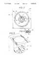
- FIG. 1is a perspective view of the filter cell cartridge assembly of the present invention
- FIG. 2is a cross-sectioned elevational view taken through FIG. 1 along 2--2;
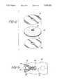
- FIG. 3is an overview of the mesh-cutting guide utilized in the present invention.
- FIG. 4is a cross-sectional view taken through one of the blades shown in FIG. 3;
- FIG. 5is an illustrative view of a cut netting blank as utilized in the present invention.
- FIG. 6is a partially exploded view of the netting utilized in the present invention adjacent the filter portion of a filter cell;
- FIG. 7is a side elevational view showing assembly of the individual components comprising a filter cell
- FIGS. 8 and 9are cross-sectional views illustrating injection-molding and the mold respectively of the sealed periphery of an individual filter cell
- FIGS. 10 and 11illustrate an assembled filter cell and assembly of a filter cell cartridge of the present invention
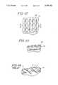
- FIGS. 12 and 13illustrate a plan and cross-sectional view respectively of the netting and filter media utilized in the present invention.
- FIG. 14shows typical filter media of prior art filter cell cartridges.
- a reinforced filter assembly 20which is comprised of a plurality cells 22-27, vertically stacked one upon the other. Disposed along the circumference of each filter cell is an edge 28 which is utilized to retain the various components of each individual cell together, as described more fully below.
- a relatively large filtration area 30is used for the introduction of unfiltered fluid (not shown) therethrough which exits through the center aperture or core 31.
- Disposed at either end of the assembly 20is an retainer ring assembly 32.
- the entire filter assembly 20is disposed inside a chamber (not shown) having an unfiltered fluid inlet for the chamber and a filtered fluid outlet connected to one or both retainer ring assemblies 32.
- FIG. 2there is shown a cross-sectional view taken through a portion of the filter cell assembly shown in FIG. 1.
- a retainer ring assembly 32is disposed at either end of the filter assembly 20.
- Retainer ring assembly 32is comprised of an end fitting 34 having an annular slot 36 therein.
- a gasket 38Disposed in the annular slot 36 is a gasket 38 which coacts with an annular outlet conduit (not shown) thereby preventing the migration of unfiltered fluid adjacent the filtration area 30 into the central aperture or core 31.
- a plurality of filter assembliesmay be disposed inside a chamber in stacked relationship thereto, thereby allowing replacement of groups of filter assemblies (not shown).
- a plurality of annular ribs 40are disposed on the underside of end fitting 34 and provide a fluid-tight fitting between the end fitting 34 and the surface of the filtration area 30, while holding and retaining mesh 42 thereon.
- the mesh 42may be sealed, e.g. ultrasonically welded, to end fitting 34.
- filter cell 22, 24is comprised of netting 42 disposed on the outer surfaces thereof.
- the nettingis preferably a mesh of the desired thickness and mesh size sufficient to withstand the forward and backward fluid flow requirements and provide for relatively undiminished fluid flow therethrough while preventing flaking and the like. Hence, this netting supplements, enhances or increases the tensile strength of the filter medium 44 when wet.
- any type of netting or meshmay be used which is pervious to flow. It is preferred however to use a polymeric mesh or netting, e.g. polypropylene. It is also preferred to have a rigidized netting or mesh which forms parallel fluid flow channels tangential to the media.
- a filter material separator 46is disposed between each of the two adjacent layers of filtration material 44.
- the separator 46is utilized to prevent collapse of the filter cell in use and provide integrity to each individual filter cell while providing relatively unimpeded fluid flow therethrough. Further, it has been observed that for "dense" filter cell cartridges when cell-to-cell spacing is minimal, the netting 42 acts as a separator between adjacent cells and therefore aids in fluid flow along the surface.
- the spacer 48is preferably comprised of the same material as the retainer ring assembly 32.
- the spacer 48has a plurality of annular recesses 50 and ridges 51 disposed on both sides. It is preferable that at least two ridges 51 are utilized (and hence two recesses 50) to form a fluid-tight seal between adjacent filtration material disposed on adjacent filter cells. Since the netting has a plurality of apertures therethrough, it has been found that two annular ridges are usually necessary to prevent migration of unfiltered fluid along the netting 42 into the central aperture or core 31.
- a plurality of bands 52engage slots 54 in the retainer ring assembly 32 and extend from the retainer ring assembly at one end to the retainer ring assembly at the other end and are used to form a rigid filter cell assembly 20.
- the bands 52are preferably of stainless steel, although any other suitable material may be utilized. Further, it is possible to utilize a plurality of threaded bolts or the like extending through the filter cell assembly and suitably attached to the retainer ring assemblies 32 in order to form a rigid assembly.
- a netting cutting dieis utilized to cut netting 56 into the appropriate configuration.
- the cutting die 56is comprised of a cutting area, shown generally at 58, disposed on a base 60. Three cutting blades are disposed on the base 60.
- An outer circumference cutting blade 62is utilized to cut the outer diameter of the netting to the approximate size of the filter cell with which it is to be used. Radially inward is disposed an additional cutting blade, designated 64.
- Another bladeis shown at 66 and is an inner circumference cutting blade. Disposed between adjacent blades are spacers 68 (shown more clearly in FIG.
- the inner circumference cutting bladehas axially disposed therein a centering hole 70 which is used for alignment or registration purposes in cutting the netting.
- Several non-cutting portionsdesignated respectively as notches 72A, 72B, are disposed on cutting blade 64.
- Each cutting bladeis generally a thin sheet stock bent into an annular configuration having one end sharpened so as form blade tip 74.
- the cutting die 56is more clearly illustrated via a representation of how the netting utilized is cut.
- the netting blankshown generally at 76, is larger than the desired area required.
- the nettingis placed onto the cutting die 56 thereby forming the appropriate cuts resulting in a number of portions. These portions include discard material 78 and filter netting 80 which is material that is actually used with the filter cell.
- the cutting blade 64results in respectively netting flaps 82A, 82B which remain attached to the netting via netting notches 84A, 84B. This therefore results in a frangible type of plug/donut 86. It has been found that it is necessary to produce the donut-type structure 86 in order to facilitate assembly of each filter cell. More particularly, the center aperture is utilized to center the netting with respect to the filtration material during the actual assembly.
- a cell assembly mandrel 102is utilized to align the various components of a filter cell. Initially placed onto mandrel 102 is a filter material separator 46. On either side of separator 46 is the filtration material 44, followed by filter netting 80. This forms the assembly shown in FIG. 6 (without the mandrel 102).
- FIGS. 8 and 9Molding of the edge 28 on each filter cell is accomplished as shown in FIGS. 8 and 9.
- a cell assembly press 100 disposed on mandrel 102 (or any other suitable or subsequent mandrel) and comprised of essentially two halvesare axially urged along mandrel 102 towards each other until mated as shown in FIG. 9.
- Thiscauses the edge of netting 80 to be compressed against filtration material 44.
- a cavity, as part of injection mold 96 contained on cell assembly press 100,is configured so as to be in the shape of edge 28 along the annular edge of the compressed filter cell. Molten material is then injected through sprue 97, of die 96, and enters into cavity 94 so as to form edge 28.
- the edge materialis the same as retainer ring assembly 32 and inter filter cell spacer 48, although any other suitable type of material may be utilized.
- the press 100is remained closed until sufficient cooling of the injected material is accomplished after which time the mold is then separated and the filter cell removed from mandrel 102.
- the netting 80thus becomes sealed to and/or an integral part of the edge seal 28.
- the edge 28, as mentioned,is comprised of plastic and has a plurality of elongate slots or apertures 110 having spacer portions 112 disposed therebetween.
- the plug or donut 86is removed as shown.
- netting notches 84A and 84Bare utilized. Therefore it is possible to merely pull on donut 86 in order to remove it from the netting 80 without performing a further cutting operation.
- the inner diameter of the plug or donut 86is only used for centering purposes about mandrel 102 during preliminary assembly steps and is removed prior to construction of the filter cell assembly 20.
- a filter assembly mandrel 114which is utilized to properly align the various components in the filter cell assembly.
- An inter filter cell spacer 48is placed between adjacent filter cells 22, 24.
- the mandrel 114is removed and the bands 52 are placed into slots 54, compressing the cells and components thereof to thereby form a rigid cohesive filter cell assembly structure 20 wherein retainer rings 34 and separators 48 are urged against the filter media and netting to thereby seal the central core 31.
- FIGS. 12 and 13top and cross-sectional views of filter netting 80 overlaid onto filtration material 44 are shown.
- the netting 80may have a relatively smooth or planar undersurface to contact the filtration material 44 or may protrude into the filter media. Both types of netting minimize cracking, flaking and the like. The netting holds down the filtration material 44 to the maximum extent possible without impeding fluid flow therethrough.
- nettingWhile a number of different types of netting were tried, type no. XN 7020 manufactured by Conwed Plastics of Minneapolis, Minn., were found to produce the best results. However, other types of netting produced by Conwed Plastics, such as part numbers XN 7025, XN 4210, XN 4700 and XN 3900 are workable. The first two of these part numbers respectively performed most satisfactorily and had a strand configuration of 7 by 5 and are a standard resin PP/PE blend. However, it is to be understood that other reinforced netting produced by other manufacturers is acceptable as individual circumstances dictate.
- the filter cellsmay be of different configurations, such as cylindrical, while different edge-type mechanisms may be utilized. Further, different types of materials may be utilized while different methods of assembly may similarly be used. Additionally, it is envisioned that it is possible to place the netting on the interior of the filter cell adjacent the filtration material so as to prevent flaking, cracking and the like during filter operation without departing from the spirit and scope of the present invention.
- the present inventionproduces an improved cell-type filter cartridge having an injection-molded edge which resiliently engages and holds reinforced netting tightly to the filter medium.
- a method of manufacturingis provided for assembling the improved filter cell cartridges so as to minimize leakage and produce an aesthetically improved filter cell which does not prematurely fail or aesthetically indicate failure.
- the present inventionalso produces an inexpensive means for improving the physical and aesthetic characteristics of a filter cell by use of a netting which minimizes the frequency at which the filter cell blinds or closes itself off while increasing mechanical and tensile strength as well as burst strength and the like.
Landscapes
- Chemical & Material Sciences (AREA)
- Chemical Kinetics & Catalysis (AREA)
- Filtering Materials (AREA)
Abstract
Description
______________________________________ Back Pressure Test Type of Cell Burst Pressure (PSI) ______________________________________ Standard/Prior art 1.5-3.0 Reinforced with netting 16.0-22.0 ______________________________________
Claims (5)
Priority Applications (1)
| Application Number | Priority Date | Filing Date | Title |
|---|---|---|---|
| US07/410,721US5055192A (en) | 1988-02-03 | 1989-09-21 | Cell-type filter cartridge retaining ring |
Applications Claiming Priority (2)
| Application Number | Priority Date | Filing Date | Title |
|---|---|---|---|
| US07/151,853US4881313A (en) | 1988-02-03 | 1988-02-03 | Method of forming a cell filter with an exposed surface |
| US07/410,721US5055192A (en) | 1988-02-03 | 1989-09-21 | Cell-type filter cartridge retaining ring |
Related Parent Applications (1)
| Application Number | Title | Priority Date | Filing Date |
|---|---|---|---|
| US07/151,853ContinuationUS4881313A (en) | 1988-02-03 | 1988-02-03 | Method of forming a cell filter with an exposed surface |
Publications (1)
| Publication Number | Publication Date |
|---|---|
| US5055192Atrue US5055192A (en) | 1991-10-08 |
Family
ID=26849028
Family Applications (1)
| Application Number | Title | Priority Date | Filing Date |
|---|---|---|---|
| US07/410,721Expired - LifetimeUS5055192A (en) | 1988-02-03 | 1989-09-21 | Cell-type filter cartridge retaining ring |
Country Status (1)
| Country | Link |
|---|---|
| US (1) | US5055192A (en) |
Cited By (24)
| Publication number | Priority date | Publication date | Assignee | Title |
|---|---|---|---|---|
| US5611925A (en)* | 1994-03-23 | 1997-03-18 | Filtration Systems, Inc. | Hub ring and supporting plate for a filter and methods for manufacturing these members |
| US5725767A (en)* | 1996-02-15 | 1998-03-10 | Calvest Associates, Inc. | Torsion resistant filter structure |
| US5759399A (en)* | 1997-01-08 | 1998-06-02 | Continuum Dynamics, Inc. | High capacity, low head loss, suction strainer for nuclear reactors |
| WO1999019042A1 (en)* | 1997-10-09 | 1999-04-22 | Schenk Filterbau Gesellschaft mit beschränkter Haftung | Filter module |
| WO1999019041A1 (en)* | 1997-10-09 | 1999-04-22 | Schenk Filterbau Gesellschaft mit beschränkter Haftung | Filter module |
| US6103122A (en)* | 1996-07-30 | 2000-08-15 | Cuno Incorporated | Filter sheet for purifying photoresist composition |
| WO2001017656A1 (en)* | 1999-09-08 | 2001-03-15 | Seitzschenk Filtersystems Gmbh | Filter module comprising tensioning elements |
| US6306300B1 (en)* | 1997-09-06 | 2001-10-23 | William Henry Harding | Filter cartridges and filter cells |
| US6502414B1 (en)* | 1998-03-20 | 2003-01-07 | General Shelters Of Texas, S.B., Ltd. | Cooler housing apparatus and method of making the same |
| US6576139B1 (en) | 1996-07-30 | 2003-06-10 | Kenneth C. Hou | Process for purifying photoresist composition employing a filter sheet |
| US20030173283A1 (en)* | 1998-08-17 | 2003-09-18 | Pulek John L. | Graded particle-size retention filter medium for fluid filtration unit with improved edge seal |
| US6712966B1 (en) | 1999-02-04 | 2004-03-30 | Cuno Incorporated | Graded particle-size retention filter medium for cell-type filter unit |
| US20040118766A1 (en)* | 2000-02-03 | 2004-06-24 | Pulek John L. | Graded particle-size retention filter medium for cell-type filter unit |
| US20040178137A1 (en)* | 2003-03-10 | 2004-09-16 | Koichi Itoh | Reinforcement structures for multi-cell filter cartridge |
| US20050040096A1 (en)* | 2003-08-21 | 2005-02-24 | Joseph Kuo | Laminated modular water filter |
| USD503222S1 (en) | 2003-09-08 | 2005-03-22 | Michael R. Hale | Evaporative cooler |
| USD505193S1 (en) | 2003-09-08 | 2005-05-17 | Michael R. Hale | Evaporative cooler |
| US20070095743A1 (en)* | 2005-11-03 | 2007-05-03 | Grodecki William J | Leaf filter system and replaceable filter leaf apparatus |
| WO2008036699A1 (en)* | 2006-09-22 | 2008-03-27 | 3M Innovative Properties Company | Method of preventing filter media cracking when compressing two or more filter media layers |
| US20100012572A1 (en)* | 2006-05-31 | 2010-01-21 | Nv Bekaert Sa | Disc-shaped filter elements and methods to provide disc-shaped filter elements |
| US20110259812A1 (en)* | 2008-11-04 | 2011-10-27 | 3M Innovative Properties Company | Filter element and seal therefor |
| US20120012519A1 (en)* | 2009-03-25 | 2012-01-19 | Illinois Tool Works Inc. | Mesh screen assembly with reduced pull-out |
| US10411448B1 (en)* | 2018-08-20 | 2019-09-10 | Siemens Industry, Inc. | Ring assembly of radially-concentric rings with quick fastening mechanism to detachably connect such rings to one another |
| US20220347603A1 (en)* | 2021-04-30 | 2022-11-03 | Pall Corporation | Filter disk segments |
Citations (18)
| Publication number | Priority date | Publication date | Assignee | Title |
|---|---|---|---|---|
| US445223A (en)* | 1891-01-27 | Filter | ||
| US2263853A (en)* | 1939-04-10 | 1941-11-25 | Oliver United Filters Inc | Filter |
| US2508976A (en)* | 1948-05-28 | 1950-05-23 | Arnold Jacobowitz | Filter device |
| US2568085A (en)* | 1947-10-10 | 1951-09-18 | John J Naugle | Filtering device |
| US2985308A (en)* | 1958-01-06 | 1961-05-23 | Infilco Inc | Filter element and system |
| US3468296A (en)* | 1967-02-03 | 1969-09-23 | Wenceslau Ramirez Duval | Rubber band projecting pistol |
| US3522885A (en)* | 1968-04-18 | 1970-08-04 | Atomic Energy Commission | Parallel flow hemodialyzer |
| US3563038A (en)* | 1969-04-03 | 1971-02-16 | Research Corp | Subterranean drain |
| US3737036A (en)* | 1970-08-26 | 1973-06-05 | Bendix Corp | Filter for polymer processing and method of manufacture |
| US4007113A (en)* | 1973-05-09 | 1977-02-08 | Amf Incorporated | Particulate filter medium and process |
| US4221663A (en)* | 1978-10-06 | 1980-09-09 | The Harshaw Chemical Company | Multiple plate filter apparatus |
| US4274964A (en)* | 1978-08-18 | 1981-06-23 | Dr. Eduard Fresenius Chemisch-Pharmazeutische Industrie Kg, Apparatebau Kg | Dialysator |
| US4305782A (en)* | 1979-04-06 | 1981-12-15 | Amf Incorporated | Filter and method of making same |
| US4309247A (en)* | 1976-03-15 | 1982-01-05 | Amf Incorporated | Filter and method of making same |
| US4361486A (en)* | 1981-04-28 | 1982-11-30 | Amf Incorporated | Filter media, method for oxidizing and removing soluble iron, method for removing and inactivating microorganisms, and particulate filter aid |
| US4617128A (en)* | 1979-09-10 | 1986-10-14 | Amf Inc. | Particulate filter aid, filter bed and process |
| US4704207A (en)* | 1985-12-02 | 1987-11-03 | Cuno Incorporated | Filter cartridge including external cell separators |
| US4871456A (en)* | 1986-08-12 | 1989-10-03 | Fuji Photo Film Co., Ltd. | Stacked filter cartridge with porous filter support |
- 1989
- 1989-09-21USUS07/410,721patent/US5055192A/ennot_activeExpired - Lifetime
Patent Citations (19)
| Publication number | Priority date | Publication date | Assignee | Title |
|---|---|---|---|---|
| US445223A (en)* | 1891-01-27 | Filter | ||
| US2263853A (en)* | 1939-04-10 | 1941-11-25 | Oliver United Filters Inc | Filter |
| US2568085A (en)* | 1947-10-10 | 1951-09-18 | John J Naugle | Filtering device |
| US2508976A (en)* | 1948-05-28 | 1950-05-23 | Arnold Jacobowitz | Filter device |
| US2985308A (en)* | 1958-01-06 | 1961-05-23 | Infilco Inc | Filter element and system |
| US3468296A (en)* | 1967-02-03 | 1969-09-23 | Wenceslau Ramirez Duval | Rubber band projecting pistol |
| US3522885A (en)* | 1968-04-18 | 1970-08-04 | Atomic Energy Commission | Parallel flow hemodialyzer |
| US3563038A (en)* | 1969-04-03 | 1971-02-16 | Research Corp | Subterranean drain |
| US3737036A (en)* | 1970-08-26 | 1973-06-05 | Bendix Corp | Filter for polymer processing and method of manufacture |
| US4007113A (en)* | 1973-05-09 | 1977-02-08 | Amf Incorporated | Particulate filter medium and process |
| US4007114A (en)* | 1973-05-09 | 1977-02-08 | Amf Incorporated | Fibrous filter medium and process |
| US4309247A (en)* | 1976-03-15 | 1982-01-05 | Amf Incorporated | Filter and method of making same |
| US4274964A (en)* | 1978-08-18 | 1981-06-23 | Dr. Eduard Fresenius Chemisch-Pharmazeutische Industrie Kg, Apparatebau Kg | Dialysator |
| US4221663A (en)* | 1978-10-06 | 1980-09-09 | The Harshaw Chemical Company | Multiple plate filter apparatus |
| US4305782A (en)* | 1979-04-06 | 1981-12-15 | Amf Incorporated | Filter and method of making same |
| US4617128A (en)* | 1979-09-10 | 1986-10-14 | Amf Inc. | Particulate filter aid, filter bed and process |
| US4361486A (en)* | 1981-04-28 | 1982-11-30 | Amf Incorporated | Filter media, method for oxidizing and removing soluble iron, method for removing and inactivating microorganisms, and particulate filter aid |
| US4704207A (en)* | 1985-12-02 | 1987-11-03 | Cuno Incorporated | Filter cartridge including external cell separators |
| US4871456A (en)* | 1986-08-12 | 1989-10-03 | Fuji Photo Film Co., Ltd. | Stacked filter cartridge with porous filter support |
Cited By (47)
| Publication number | Priority date | Publication date | Assignee | Title |
|---|---|---|---|---|
| USRE36133E (en)* | 1994-03-23 | 1999-03-09 | Nagase & Co. Ltd. | Hub ring and supporting plate for a filter and methods for manufacturing these members |
| US5755034A (en)* | 1994-03-23 | 1998-05-26 | Nagase & Co., Ltd. | Method for manufacturing a hub ring for a filter |
| US5611925A (en)* | 1994-03-23 | 1997-03-18 | Filtration Systems, Inc. | Hub ring and supporting plate for a filter and methods for manufacturing these members |
| US5788860A (en)* | 1994-03-23 | 1998-08-04 | Nagase & Co., Ltd. And Kabushiki Kaisha Toukai Spring Seisakusho | Method for manufacturing a supporting plate for a filter |
| US5829138A (en)* | 1994-03-23 | 1998-11-03 | Nagase & Co., Ltd. | Hub ring and supporting plate for a filter and methods for manufacturing these members |
| US5858230A (en)* | 1994-03-23 | 1999-01-12 | Nagase & Co. Ltd. | Hub ring and supporting plate for a filter |
| US5725767A (en)* | 1996-02-15 | 1998-03-10 | Calvest Associates, Inc. | Torsion resistant filter structure |
| US6733677B2 (en) | 1996-07-30 | 2004-05-11 | Cuno Incorporated | Filter sheet and process for purifying photoresist composition employing the filter sheet |
| US6103122A (en)* | 1996-07-30 | 2000-08-15 | Cuno Incorporated | Filter sheet for purifying photoresist composition |
| US6576139B1 (en) | 1996-07-30 | 2003-06-10 | Kenneth C. Hou | Process for purifying photoresist composition employing a filter sheet |
| US5759399A (en)* | 1997-01-08 | 1998-06-02 | Continuum Dynamics, Inc. | High capacity, low head loss, suction strainer for nuclear reactors |
| US6306300B1 (en)* | 1997-09-06 | 2001-10-23 | William Henry Harding | Filter cartridges and filter cells |
| WO1999019042A1 (en)* | 1997-10-09 | 1999-04-22 | Schenk Filterbau Gesellschaft mit beschränkter Haftung | Filter module |
| WO1999019041A1 (en)* | 1997-10-09 | 1999-04-22 | Schenk Filterbau Gesellschaft mit beschränkter Haftung | Filter module |
| US6306298B1 (en) | 1997-10-09 | 2001-10-23 | Seitz-Schenk Filtersystems Gmbh | Filter module |
| US6502414B1 (en)* | 1998-03-20 | 2003-01-07 | General Shelters Of Texas, S.B., Ltd. | Cooler housing apparatus and method of making the same |
| US20030173283A1 (en)* | 1998-08-17 | 2003-09-18 | Pulek John L. | Graded particle-size retention filter medium for fluid filtration unit with improved edge seal |
| US20050167353A1 (en)* | 1998-08-17 | 2005-08-04 | Pulek John L. | Graded particle-size retention filter medium for fluid filtration unit with improved edge seal |
| US7582209B2 (en) | 1998-08-17 | 2009-09-01 | 3M Innovative Properties Company | Graded particle-size retention filter medium for fluid filtration unit with improved edge seal |
| US20070062859A1 (en)* | 1998-08-17 | 2007-03-22 | 3M Innovative Properties Company | Graded particle-size retention filter medium for fluid filtration unit with improved edge seal |
| US7178676B2 (en) | 1998-08-17 | 2007-02-20 | 3M Innovative Properties Company | Graded particle-size retention filter medium for fluid filtration unit with improved edge seal |
| US6939466B2 (en) | 1998-08-17 | 2005-09-06 | Cuno Incorporated | Graded particle-size retention filter medium for fluid filtration unit with improved edge seal |
| US6712966B1 (en) | 1999-02-04 | 2004-03-30 | Cuno Incorporated | Graded particle-size retention filter medium for cell-type filter unit |
| US6749751B1 (en) | 1999-09-08 | 2004-06-15 | Seitzschenk Filtersystems Gmbh | Filter module comprising tensioning elements |
| WO2001017656A1 (en)* | 1999-09-08 | 2001-03-15 | Seitzschenk Filtersystems Gmbh | Filter module comprising tensioning elements |
| US20040118766A1 (en)* | 2000-02-03 | 2004-06-24 | Pulek John L. | Graded particle-size retention filter medium for cell-type filter unit |
| WO2004080569A1 (en)* | 2003-03-10 | 2004-09-23 | Cuno, Incorporated | Reinforcement structures for multi-cell filter cartridge |
| US20040178137A1 (en)* | 2003-03-10 | 2004-09-16 | Koichi Itoh | Reinforcement structures for multi-cell filter cartridge |
| US20050040096A1 (en)* | 2003-08-21 | 2005-02-24 | Joseph Kuo | Laminated modular water filter |
| USD503222S1 (en) | 2003-09-08 | 2005-03-22 | Michael R. Hale | Evaporative cooler |
| USD505193S1 (en) | 2003-09-08 | 2005-05-17 | Michael R. Hale | Evaporative cooler |
| US20110174715A1 (en)* | 2005-11-03 | 2011-07-21 | Grodecki William J | Leaf filter system and replaceable filter leaf apparatus |
| US7922905B2 (en)* | 2005-11-03 | 2011-04-12 | Grodecki William J | Leaf filter system and replaceable filter leaf apparatus |
| US8425774B2 (en) | 2005-11-03 | 2013-04-23 | William J. Grodecki | Leaf filter system and replaceable filter leaf apparatus |
| US20070095743A1 (en)* | 2005-11-03 | 2007-05-03 | Grodecki William J | Leaf filter system and replaceable filter leaf apparatus |
| US8075775B2 (en) | 2005-11-03 | 2011-12-13 | Grodecki William J | Leaf filter system and replaceable filter leaf apparatus |
| US20100012572A1 (en)* | 2006-05-31 | 2010-01-21 | Nv Bekaert Sa | Disc-shaped filter elements and methods to provide disc-shaped filter elements |
| WO2008036699A1 (en)* | 2006-09-22 | 2008-03-27 | 3M Innovative Properties Company | Method of preventing filter media cracking when compressing two or more filter media layers |
| US20100044299A1 (en)* | 2006-09-22 | 2010-02-25 | Duval Neal M | Method of preventing filter media cracking when compressing two or more filter media layers |
| US8636151B2 (en) | 2006-09-22 | 2014-01-28 | 3M Innovative Properties Company | Method of preventing filter media cracking when compressing two or more filter media layers |
| US20110259812A1 (en)* | 2008-11-04 | 2011-10-27 | 3M Innovative Properties Company | Filter element and seal therefor |
| US10918985B2 (en)* | 2008-11-04 | 2021-02-16 | 3M Innovative Properties Company | Filter element and seal therefor |
| US20120012519A1 (en)* | 2009-03-25 | 2012-01-19 | Illinois Tool Works Inc. | Mesh screen assembly with reduced pull-out |
| US8651283B2 (en)* | 2009-03-25 | 2014-02-18 | Illinois Tool Works Inc. | Mesh screen assembly with reduced pull-out |
| US10411448B1 (en)* | 2018-08-20 | 2019-09-10 | Siemens Industry, Inc. | Ring assembly of radially-concentric rings with quick fastening mechanism to detachably connect such rings to one another |
| US20220347603A1 (en)* | 2021-04-30 | 2022-11-03 | Pall Corporation | Filter disk segments |
| US12220657B2 (en)* | 2021-04-30 | 2025-02-11 | Pall Corporation | Filter disk segments |
Similar Documents
| Publication | Publication Date | Title |
|---|---|---|
| US4881313A (en) | Method of forming a cell filter with an exposed surface | |
| US5055192A (en) | Cell-type filter cartridge retaining ring | |
| US10918985B2 (en) | Filter element and seal therefor | |
| US4876007A (en) | Plate-type filter cartridge with internal support | |
| US4725323A (en) | Filter element | |
| US3327864A (en) | Filter cartridge unit and porous filter element for use in connection therewith | |
| US4680118A (en) | Pleated and sealed filter cartridge with connected film | |
| US6739459B1 (en) | Filter element including bonded end caps and support core | |
| EP1444024B1 (en) | Filter module and method for its manufacture | |
| US8640884B2 (en) | Fluid treatment elements and fluid treatment arrangements with spaces between fluid treatment elements and methods for making and using them | |
| WO1985002553A1 (en) | Filter apparatus for polymers | |
| EP1412048B1 (en) | A filter cartridge | |
| US7261817B2 (en) | Filter module and device for static filtration of fluids with such a module | |
| AU4717599A (en) | Filter element and method of making a filter element | |
| JPWO2003099417A1 (en) | High viscosity fluid filter unit and spinning pack | |
| US8911633B2 (en) | Fluid treatment elements and fluid treatment arrangements with posts and/or bands between fluid treatment elements and methods for making and using them | |
| US20100219139A1 (en) | Fluid treatment arrangements with fluid treatment elements and methods for making and using them | |
| CN213101060U (en) | Filter device | |
| KR100340983B1 (en) | Molten resin filter device | |
| DE102010032788A1 (en) | Filter disk for filtering apparatus to filter fluid i.e. plastic melt, has circular upper and lower filter elements provided with pressure tight joint at internal diameters, where elements are firmly connected with one another |
Legal Events
| Date | Code | Title | Description |
|---|---|---|---|
| FEPP | Fee payment procedure | Free format text:PAYOR NUMBER ASSIGNED (ORIGINAL EVENT CODE: ASPN); ENTITY STATUS OF PATENT OWNER: LARGE ENTITY | |
| FPAY | Fee payment | Year of fee payment:4 | |
| AS | Assignment | Owner name:MELLON BANK, N.A., PENNSYLVANIA Free format text:SECURITY AGREEMENT;ASSIGNOR:CUNO INCORPORATED;REEL/FRAME:008430/0229 Effective date:19960809 Owner name:MELLON BANK, N.A., PENNSYLVANIA Free format text:SECURITY AGREEMENT;ASSIGNOR:CUNO INCORPORATED;REEL/FRAME:008376/0272 Effective date:19960809 | |
| REMI | Maintenance fee reminder mailed | ||
| FPAY | Fee payment | Year of fee payment:8 | |
| SULP | Surcharge for late payment | ||
| REIN | Reinstatement after maintenance fee payment confirmed | ||
| FP | Lapsed due to failure to pay maintenance fee | Effective date:20031008 | |
| FEPP | Fee payment procedure | Free format text:PETITION RELATED TO MAINTENANCE FEES FILED (ORIGINAL EVENT CODE: PMFP); ENTITY STATUS OF PATENT OWNER: LARGE ENTITY | |
| FEPP | Fee payment procedure | Free format text:PETITION RELATED TO MAINTENANCE FEES GRANTED (ORIGINAL EVENT CODE: PMFG); ENTITY STATUS OF PATENT OWNER: LARGE ENTITY | |
| FPAY | Fee payment | Year of fee payment:12 | |
| SULP | Surcharge for late payment | ||
| PRDP | Patent reinstated due to the acceptance of a late maintenance fee | Effective date:20040909 | |
| STCF | Information on status: patent grant | Free format text:PATENTED CASE | |
| AS | Assignment | Owner name:CUNO INCORPORATED, CONNECTICUT Free format text:RELEASE OF SECURITY INTERESTS;ASSIGNOR:MELLON BANK N.A.;REEL/FRAME:016334/0680 Effective date:20050715 | |
| AS | Assignment | Owner name:3M INNOVATIVE PROPERTIES COMPANY, MINNESOTA Free format text:ASSIGNMENT OF ASSIGNORS INTEREST;ASSIGNOR:CUNO, INCORPORATED;REEL/FRAME:017325/0937 Effective date:20060210 |