US5055101A - Variable shape guide apparatus - Google Patents
Variable shape guide apparatusDownload PDFInfo
- Publication number
- US5055101A US5055101AUS07/447,927US44792789AUS5055101AUS 5055101 AUS5055101 AUS 5055101AUS 44792789 AUS44792789 AUS 44792789AUS 5055101 AUS5055101 AUS 5055101A
- Authority
- US
- United States
- Prior art keywords
- memory element
- shape
- temperature
- guide member
- memory
- Prior art date
- Legal status (The legal status is an assumption and is not a legal conclusion. Google has not performed a legal analysis and makes no representation as to the accuracy of the status listed.)
- Expired - Lifetime
Links
- 238000010438heat treatmentMethods0.000claimsabstractdescription15
- 238000001816coolingMethods0.000claimsabstractdescription13
- 239000000463materialSubstances0.000claimsdescription19
- 238000009413insulationMethods0.000claimsdescription10
- 239000011248coating agentSubstances0.000claimsdescription6
- 238000000576coating methodMethods0.000claimsdescription6
- 238000004891communicationMethods0.000claimsdescription5
- 229910001285shape-memory alloyInorganic materials0.000description14
- 230000008878couplingEffects0.000description12
- 238000010168coupling processMethods0.000description12
- 238000005859coupling reactionMethods0.000description12
- 239000000523sampleSubstances0.000description11
- 230000007704transitionEffects0.000description11
- 239000012530fluidSubstances0.000description9
- 230000006870functionEffects0.000description7
- 230000006835compressionEffects0.000description6
- 238000007906compressionMethods0.000description6
- 210000000056organAnatomy0.000description6
- 230000008901benefitEffects0.000description5
- 230000008859changeEffects0.000description5
- 238000010276constructionMethods0.000description5
- 230000008602contractionEffects0.000description5
- 238000004804windingMethods0.000description5
- 238000005452bendingMethods0.000description4
- 230000001939inductive effectEffects0.000description4
- 238000000034methodMethods0.000description4
- 239000004033plasticSubstances0.000description4
- 229920003023plasticPolymers0.000description4
- 238000005476solderingMethods0.000description4
- 239000004809TeflonSubstances0.000description3
- 229920006362Teflon®Polymers0.000description3
- 238000002347injectionMethods0.000description3
- 239000007924injectionSubstances0.000description3
- 238000003780insertionMethods0.000description3
- 230000037431insertionEffects0.000description3
- 229910052751metalInorganic materials0.000description3
- 229910001000nickel titaniumInorganic materials0.000description3
- 230000004044responseEffects0.000description3
- BFKJFAAPBSQJPD-UHFFFAOYSA-NtetrafluoroetheneChemical compoundFC(F)=C(F)FBFKJFAAPBSQJPD-UHFFFAOYSA-N0.000description3
- 238000003466weldingMethods0.000description3
- BQCIDUSAKPWEOX-UHFFFAOYSA-N1,1-DifluoroetheneChemical compoundFC(F)=CBQCIDUSAKPWEOX-UHFFFAOYSA-N0.000description2
- JOYRKODLDBILNP-UHFFFAOYSA-NEthyl urethaneChemical compoundCCOC(N)=OJOYRKODLDBILNP-UHFFFAOYSA-N0.000description2
- 229920006370KynarPolymers0.000description2
- 239000004698PolyethyleneSubstances0.000description2
- 239000000853adhesiveSubstances0.000description2
- 230000001070adhesive effectEffects0.000description2
- 229910045601alloyInorganic materials0.000description2
- 239000000956alloySubstances0.000description2
- 238000004873anchoringMethods0.000description2
- 230000036760body temperatureEffects0.000description2
- 230000001276controlling effectEffects0.000description2
- 238000002788crimpingMethods0.000description2
- 238000013461designMethods0.000description2
- 239000000835fiberSubstances0.000description2
- -1polyethylenePolymers0.000description2
- 229920000573polyethylenePolymers0.000description2
- 230000001105regulatory effectEffects0.000description2
- 230000000717retained effectEffects0.000description2
- 238000004904shorteningMethods0.000description2
- 239000010963304 stainless steelSubstances0.000description1
- 229920002799BoPETPolymers0.000description1
- 239000004593EpoxySubstances0.000description1
- 239000005041Mylar™Substances0.000description1
- 239000004677NylonSubstances0.000description1
- 229910000589SAE 304 stainless steelInorganic materials0.000description1
- 230000000712assemblyEffects0.000description1
- 238000000429assemblyMethods0.000description1
- 210000004204blood vesselAnatomy0.000description1
- 239000004020conductorSubstances0.000description1
- 230000000593degrading effectEffects0.000description1
- 238000009826distributionMethods0.000description1
- 238000010292electrical insulationMethods0.000description1
- 230000001747exhibiting effectEffects0.000description1
- 238000010348incorporationMethods0.000description1
- 238000009434installationMethods0.000description1
- 238000004519manufacturing processMethods0.000description1
- 229910000734martensiteInorganic materials0.000description1
- 239000012528membraneSubstances0.000description1
- 230000006386memory functionEffects0.000description1
- 239000002184metalSubstances0.000description1
- 238000012986modificationMethods0.000description1
- 230000004048modificationEffects0.000description1
- HLXZNVUGXRDIFK-UHFFFAOYSA-Nnickel titaniumChemical compound[Ti].[Ti].[Ti].[Ti].[Ti].[Ti].[Ti].[Ti].[Ti].[Ti].[Ti].[Ni].[Ni].[Ni].[Ni].[Ni].[Ni].[Ni].[Ni].[Ni].[Ni].[Ni].[Ni].[Ni].[Ni]HLXZNVUGXRDIFK-UHFFFAOYSA-N0.000description1
- 229920001778nylonPolymers0.000description1
- 230000003287optical effectEffects0.000description1
- 230000031070response to heatEffects0.000description1
- 230000006903response to temperatureEffects0.000description1
- 239000012781shape memory materialSubstances0.000description1
- 229910000679solderInorganic materials0.000description1
- 239000010935stainless steelSubstances0.000description1
- 229910001220stainless steelInorganic materials0.000description1
- 230000002459sustained effectEffects0.000description1
- 230000009466transformationEffects0.000description1
- 230000001960triggered effectEffects0.000description1
Images


Classifications
- A—HUMAN NECESSITIES
- A61—MEDICAL OR VETERINARY SCIENCE; HYGIENE
- A61B—DIAGNOSIS; SURGERY; IDENTIFICATION
- A61B1/00—Instruments for performing medical examinations of the interior of cavities or tubes of the body by visual or photographical inspection, e.g. endoscopes; Illuminating arrangements therefor
- A61B1/005—Flexible endoscopes
- A61B1/0051—Flexible endoscopes with controlled bending of insertion part
- A—HUMAN NECESSITIES
- A61—MEDICAL OR VETERINARY SCIENCE; HYGIENE
- A61M—DEVICES FOR INTRODUCING MEDIA INTO, OR ONTO, THE BODY; DEVICES FOR TRANSDUCING BODY MEDIA OR FOR TAKING MEDIA FROM THE BODY; DEVICES FOR PRODUCING OR ENDING SLEEP OR STUPOR
- A61M25/00—Catheters; Hollow probes
- A61M25/01—Introducing, guiding, advancing, emplacing or holding catheters
- A61M25/0105—Steering means as part of the catheter or advancing means; Markers for positioning
- A61M25/0133—Tip steering devices
- A61M25/0158—Tip steering devices with magnetic or electrical means, e.g. by using piezo materials, electroactive polymers, magnetic materials or by heating of shape memory materials
- A—HUMAN NECESSITIES
- A61—MEDICAL OR VETERINARY SCIENCE; HYGIENE
- A61M—DEVICES FOR INTRODUCING MEDIA INTO, OR ONTO, THE BODY; DEVICES FOR TRANSDUCING BODY MEDIA OR FOR TAKING MEDIA FROM THE BODY; DEVICES FOR PRODUCING OR ENDING SLEEP OR STUPOR
- A61M25/00—Catheters; Hollow probes
- A61M25/01—Introducing, guiding, advancing, emplacing or holding catheters
- A61M25/09—Guide wires
- H—ELECTRICITY
- H01—ELECTRIC ELEMENTS
- H01H—ELECTRIC SWITCHES; RELAYS; SELECTORS; EMERGENCY PROTECTIVE DEVICES
- H01H37/00—Thermally-actuated switches
- H01H37/02—Details
- H01H37/32—Thermally-sensitive members
- H01H37/323—Thermally-sensitive members making use of shape memory materials
- A—HUMAN NECESSITIES
- A61—MEDICAL OR VETERINARY SCIENCE; HYGIENE
- A61M—DEVICES FOR INTRODUCING MEDIA INTO, OR ONTO, THE BODY; DEVICES FOR TRANSDUCING BODY MEDIA OR FOR TAKING MEDIA FROM THE BODY; DEVICES FOR PRODUCING OR ENDING SLEEP OR STUPOR
- A61M25/00—Catheters; Hollow probes
- A61M25/01—Introducing, guiding, advancing, emplacing or holding catheters
- A61M25/09—Guide wires
- A61M2025/09133—Guide wires having specific material compositions or coatings; Materials with specific mechanical behaviours, e.g. stiffness, strength to transmit torque
- A61M2025/09141—Guide wires having specific material compositions or coatings; Materials with specific mechanical behaviours, e.g. stiffness, strength to transmit torque made of shape memory alloys which take a particular shape at a certain temperature
- C—CHEMISTRY; METALLURGY
- C08—ORGANIC MACROMOLECULAR COMPOUNDS; THEIR PREPARATION OR CHEMICAL WORKING-UP; COMPOSITIONS BASED THEREON
- C08L—COMPOSITIONS OF MACROMOLECULAR COMPOUNDS
- C08L2201/00—Properties
- C08L2201/12—Shape memory
- H—ELECTRICITY
- H01—ELECTRIC ELEMENTS
- H01H—ELECTRIC SWITCHES; RELAYS; SELECTORS; EMERGENCY PROTECTIVE DEVICES
- H01H37/00—Thermally-actuated switches
- H01H37/02—Details
- H01H37/32—Thermally-sensitive members
- H01H37/46—Thermally-sensitive members actuated due to expansion or contraction of a solid
- H01H37/50—Thermally-sensitive members actuated due to expansion or contraction of a solid with extensible wires under tension
Definitions
- the present inventionrelates to guide apparatus, probes, and the like, and particularly to guide apparatus that are steerable through body cavities and aimable at obstructions, organs, or tissue within the body from a position external to the body. More particularly, the present invention relates to maneuverable guide apparatus including spring means for biasing a temperature-activated memory element to alter the shape of the memory element upon cooling of the memory element to a temperature below its martensitic transformation temperature.
- the distal end of the catheteris formed into a desired shape by using a material exhibiting mechanical memory that is triggered by heat.
- the distal end of the catheteris shaped to anchor the catheter within the body.
- the change of the shape or other movement of the distal end in these prior devicesis limited to a single direction. Once the memory material has been heated causing the distal end to move in said single direction to assume its characteristic anchoring shape, it becomes necessary to deform the distal end manually at a temperature below the transition temperature of the mechanical memory material in order to change the shape of the distal end.
- the need for manual manipulation of a catheter once it is inserted into bodylimits the steerability and aimability of the catheter.
- One object of the present inventionis to provide a steerable guide apparatus, probe, and the like which is easy to operate and steerable in a plurality of different directions within the body.
- Another object of the present inventionis to provide an aimable guide apparatus, probe, and the like which is easy to operate and which can be aimed at obstructions, organs, or tissues in a plurality of different directions within the body.
- Yet another object of the present inventionis to provide a guide apparatus, probe, and the like of improved maneuverability having means for slidably coupling each of a plurality of temperature-activated memory elements to a core member so that each memory element is permitted to slip in relation to the adjacent core member when at least one of the memory elements is heated to assume a predetermined "memorized" shape.
- Another object of the present inventionis to provide a steerable and aimable guide apparatus, probe, and the like of very simple design having only one temperature-activated memory element that is movable to a predetermined shape using remote controls to steer and aim the guide apparatus and yet is automatically returnable to an initial shape without manual manipulation by an operator.
- Still another object of the present inventionis to provide a highly maneuverable guide apparatus, probe, and the like having at least one resilient element for biasing the distal end of the guide apparatus to assume an initial shape and a separate temperature-activated memory element that is movable under heat to bend the distal end of the guide apparatus to a multiplicity of shapes other than the initial shape.
- Another object of the present inventionis to provide a steerable and aimable guide apparatus, probe, and the like of simple construction wherein a memory element is employed to deflect a guide wire made of spring material.
- Yet another object of the present inventionis to provide a steerable and aimable guide apparatus, probe, and the like wherein the guide wire is made of a resilient shape-memory material.
- Still another object of the present inventionis to provide a steerable and aimable guide apparatus, probe, and the like wherein a temperature-activated memory element made of a shape-memory alloy and employed to deflect a guide wire made of spring material is coupled to the guide wire to apply an axial compression pulling force to the guide wire as the length of the memory element is shortened upon being heated to a predetermined temperature in accordance with a thermal property of the shape-memory alloy so that the guide wire is "pulled" along its axis by the memory element to assume a different shape.
- a maneuverable distal apparatusincludes a temperature-activated memory element moving in a first direction to assume a predetermined shape when heated to a predetermined temperature and spring means for yieldably urging the memory element in a second direction away from the first direction upon cooling of the memory element to a temperature less than the predetermined temperature so that the memory element is moved to assume a shape other than the predetermined shape.
- the apparatusalso includes insulation means for preventing unwanted electrically conductive contact between the memory element and the spring means and control means for selectively heating the memory element so that the memory element is moved in the first direction.
- the spring meansis an elongated coil spring formed to include a longitudinal cavity and the memory element is positioned in the longitudinal cavity.
- the insulation meansincludes a tubular sleeve positioned in the longitudinal cavity and the memory element is positioned in the tubular sleeve.
- An end capis coupled to a distal end of the elongated coil spring and the insulation means includes means for preventing electrically conductive contact between the memory element and the end cap.
- the control meansincludes power supply means, first electrical lead means for coupling the power supply means and the spring means in electrical communication, and second electrical lead means for coupling the power supply means and the memory element in electrical communication.
- Circuit means interconnecting the spring means and the memory elementis provided for establishing an electrical circuit electrically connecting the spring means, the memory element, and the control means in series.
- the guide wireis a tubular coiled spring made of a resilient shape-memory alloy.
- Control meansis provided for selectively heating the tubular coiled spring to at least a predetermined temperature so that the tubular coiled spring moves from its initial shape to assume its predetermined shape.
- the tubular coiled springreturns toward its initial shape upon being cooled to a temperature less than the predetermined temperature.
- the memory elementis disposed inside a hollow axially compressible guide wire made of spring material and anchored at its opposite ends to spaced-apart distal and proximal portions of the guide wire.
- the "double-anchored" memory elementshortens in length in accordance with due to a characteristic thermal property of the shape-memory alloy comprising the memory element upon being heated to a predetermined temperature. Such shortening acts to apply an axial compression load to the axially compressible guide wire, thereby effectively "pulling" the guide wire to assume a different shape.
- the guide wirereturns toward its initial shape upon cooling of the memory element to a temperature less than the predetermined temperature due, in part, to spring characteristics of the guide wire.
- FIG. 1is a perspective view of a steerable and aimable guide apparatus embodying the present invention
- FIG. 2is a longitudinal cross-sectional view, partly broken away, of a body cavity and the distal end of the guide apparatus shown in FIG. 1;
- FIG. 3is a perspective view of an embodiment of a temperature-activated memory element employed in the guide apparatus showing its different shapes;
- FIG. 4is a transverse cross-sectional view of the distal end of the guide apparatus embodying the present invention taken generally along section lines 4--4 in FIG. 2;
- FIG. 5is a longitudinal cross-sectional view of a body cavity showing the aimable feature of a guide apparatus embodying the present invention
- FIG. 6is a transverse cross-sectional view of the embodiment of the guide apparatus shown in FIG. 5 taken generally along section lines 6--6 of FIG. 5;
- FIG. 7is a perspective view of an embodiment of a plurality of temperature-activated memory elements employed in the distal end of the guide apparatus to deflect or move the distal end for steering and aiming thereof;
- FIG. 8is an exploded view of another embodiment of the present invention.
- FIG. 9is a longitudinal sectional view, partly broken away, showing the embodiment of FIG. 8 in its relaxed position and taken generally along section lines 9--9 of FIG. 8;
- FIG. 10is a view, partly broken away, of the embodiment of FIG. 9 rotated 90° about its longitudinal axis;
- FIG. 11is a longitudinal sectional view, partly broken away, showing the embodiment of FIG. 8 in a deflected position
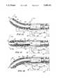
- FIG. 12is a longitudinal sectional view of yet another embodiment of the present invention, partly broken away, showing the distal end of a guide apparatus in a relaxed position;
- FIG. 13is a view of the embodiment of FIG. 12, partly broken away, showing the distal end of the guide apparatus in a partially deflected position;
- FIG. 14is a view of the embodiment of FIG. 12, partly broken away, showing the distal end of the guide apparatus in a fully deflected position;
- FIG. 15is a longitudinal sectional view of another embodiment of the present invention showing a temperature-activated memory element positioned within a coiled spring;
- FIG. 16is a longitudinal sectional view of yet another embodiment of the present invention.
- FIG. 17is a longitudinal sectional view of still another embodiment of the present invention showing a type of circuit means different than that shown in FIGS. 15 and 16;
- FIG. 18is a transverse sectional view, taken generally along lines 18--18 of FIG. 17, showing rotation of a guide wire in a clockwise direction about its longitudinal axis in response to heating the temperature-activated memory element inside above its transition temperature;
- FIG. 19is a longitudinal sectional view of yet another embodiment of the present invention having a temperature-activated memory element configured to provide its own spring return means;
- FIG. 20is a longitudinal sectional view of still another embodiment of the present invention having a double-anchored temperature-activated memory element arranged to apply pulling force to its companion spring return means during movement of the memory element to assume a predetermined shape under thermal loading; and
- FIG. 21is a longitudinal sectional view of yet another embodiment of the present invention having a double-anchored temperature-activated memory element coupled directly to a current source.
- FIG. 1A catheter 10 embodying the present invention is shown generally in FIG. 1.
- Catheter 10includes an elongated tubular member 12 having a proximal end 14 and a steerable and aimable distal end 16.
- the tubular member 12is formed of plastic, TEFLON, or cross-linked kynar or polyethylene.
- tubular member 12it is desirable that tubular member 12 be formed of a material that is flexible, that can withstand heat, and which provides electrical insulation.
- the tubular member 12can have a lumen 18 for the passage of fluid from the proximal end 14 to the distal end 16 and vice versa.
- the tubular member 12includes one or more holes or openings 19 through which fluids are either injected into or drained from a body cavity.
- Some cannulaemay have an open distal end 16 for insertion and withdrawal of medical instruments.
- a plurality of temperature-activated memory elements 20are incorporated into the distal end 16 of the tubular member 12. It may be desirable to isolate the memory elements 20 from the body cavity.
- the temperature-activated memory elements 20preferably exhibit a memory characteristic in response to temperature changes.
- the elements 20may be wires or flat strips such as shown in FIG. 3.
- the temperature-activated memory elements 20are formed of a mechanical memory metal such as a nickel titanium alloy. While a nickel titanium alloy is desirable, other metal elements having a memory characteristic related to temperature could be used without departing from the scope of the invention. Such metal elements should have a high resistance to electric current so that heat is produced when current is passed therethrough.
- the elements 20have a body portion 22 and a tip portion 24.
- Each element 20has a first or preset shape represented by the broken lines in FIG. 3 and a second shape represented by the solid lines in FIG. 3.
- the preset shapeis an arcuate shape, and the second shape is a straight shape. It will be appreciated that the preset shape could be any shape.
- Each temperature-activated memory element 20is originally annealed into its preset shape (represented by the broken lines in FIG. 3).
- Memory elements 20are cooled and straightened to their second shape (represented by the solid lines in FIG. 3) before incorporation into the distal end 16 of the tubular member 12.
- the elements 20are again heated to a predetermined transitional temperature they return to their preset shape.
- the predetermined transitional temperatureis any temperature above body temperature.
- the predetermined transitional temperaturemay be in the range of 100° to 150° F.
- the memory elements 20can either be directly incorporated into the distal end 16 of the tubular member 12 or can be carried on an electrically insulative core 50. As will be discussed later, each memory element 20 must be coupled to at least one other memory element 20 so that when one of the memory elements is heated it applies a force to move the other memory element 20.
- the catheter 10further includes an electronic control system 30 for controlling current flow to vary the temperature of each temperature-activated memory element 20 from a position external to the body so as to deflect the distal end 16 of the tubular member 12 in a plurality of different directions corresponding to the preset shapes of the elements 20.
- the control system 30includes a power supply source 32 which may be either AC or DC.
- the system 30also includes a control device 34 which, in the illustrative embodiment, is similar to a "joystick" control, tactile membrane switch, or ball controller. It will be appreciated that various types of control devices 34 may be employed without departing from the scope of the present invention.
- the power supply source 32is coupled through control device 34 to the tubular member 12 by cable 36 and a coupling device 38. Further, the temperature-activated memory elements 20 are electrically connected to the control device 34 through cable 36 and coupling 38 by electrical wires 40 which are attached to the body portions 22 of memory elements 20 by conventional means 42 such as soldering or crimping. Return or ground wires 44 are attached to the tip portions 24 of memory elements 20 by conventional means such as soldering or crimping 46. Return or ground wires 44 may be combined into a single ground cable 48 as shown in FIG. 2.
- the temperature-activated memory elements 20are carried on the exterior of the core 50 and ground wire 48 runs through the interior of the core 50.
- Core 50couples each memory element 20 to at least one other memory element 20 so that when a memory element 20 moves to assume its preset shape in response to heat it applies a force to move the other memory element 20 coupled thereto.
- the core 50is a tube formed of urethane having a wall thickness of about 0.005 inch.
- the core 50may be a fiber optics bundle, electrical wire, microinstrumentation, or any other suitable member.
- Other mounting arrangementscould be used for incorporating the memory elements 20 into the distal end 16 of the tubular member 12 without departing from the scope of the present invention.
- the distal end 16 of the tubular member 12is inserted into a body cavity 60 such as a blood vessel while memory elements 20 are straight and at a temperature below the transitional temperature.
- each memory element 20is in its second shape for ready insertion of the distal end 16 into the body cavity 60.
- the tubular member 12is pushed through cavity 60 until it reaches a desired branch 62 or 64 extending from the cavity 60.
- Control device 34is manipulated to apply an electrical voltage or current to one or more of the memory elements 20. Because of the high resistance of memory elements 20, heat is generated.
- a memory elementis heated to its predetermined transitional temperature (i.e., a predetermined temperature above body temperature) the memory element 20 moves to assume its preset shape (as shown by the broken lines in FIG.
- the other memory element 20When the other memory element 20 reaches its predetermined transitional temperature, it begins to move to assume its preset shape and in doing so applies a force to the memory element 20 coupled thereto to move it to its second shape (as shown by the solid lines in FIG. 3).
- the catheter tubular member 12can continue to be pushed through the branch 62 or 64 until it is again desirable to turn or bend the catheter 10.
- four temperature-activated memory elements 20may be carried on the exterior of core 50.
- pairs of the memory elements 20are shown diametrically opposed to each other so that opposed elements 20 apply forces to each other when they are heated.
- the distal end 16may be deflected in at least four different directions by applying an electrical current or voltage to one of the memory elements 20.
- more or less than four memory elements 20may be utilized without departing from the scope of the present invention.
- at least two memory elements 20are required.
- the control system 30may include means for regulating the application of current or voltage applied to the memory elements 20 to allow virtually an unlimited number of directions in which the distal end 16 may be deflected for the purpose of steering the catheter tubular member 10 through body cavities. It will be appreciated that a large number of wire memory elements could be incorporated into the distal end 16 and a voltage or current applied to one or more of the wires to deflect the distal end 16 in a desired direction.
- FIGS. 5 and 6Another application for a catheter 70 embodying the present invention is shown in FIGS. 5 and 6. Reference numerals from FIGS. 1-4 have been applied to the catheter 70 shown in FIGS. 5 and 6 where the same or similar parts are being used.
- Catheter 70includes a tubular member 72 having a distal end 76.
- the distal end 76includes a plurality of temperature-activated memory elements 20 of the type previously described.
- the same or similar control systemmay be employed in connection with the catheter 70 in a body cavity 80 for the purpose of aiming the distal end 76 at an obstruction, organ, or tissue 82 within the cavity 80.
- the catheter 70may be anchored in the cavity 80 by a balloon 78. Once the catheter 70 is anchored, the distal end 76 is aimed in one of a plurality of directions to establish a course for the injection of fluid or a laser beam at the organ or tissue 82.
- a core 90 formed of insulative materialpasses through tubular member 72.
- Memory elements 20are carried on the core 90 between the core 90 and the tubular member 72.
- Core 90serves to couple each memory element 20 to at least one other memory element 20 in the manner and for the purpose previously described.
- the hollow core 90may include a first tube 92 for carrying a fluid from the proximal end of the catheter 70 to the distal end 76.
- a return tube 94may be included for extracting fluid. It will be appreciated that either passage 92 or 94 may be used for inserting a medical instrument into the cavity 80.
- Core 90may also include a transparent member 95 providing a lens for observing the obstruction, organ, or tissue 82 and a bundle of fiber-optic lines 96 for transmitting light or a laser beam to the distal end 76.
- catheter 70has a distal end 76 which is aimable in a plurality of directions in accordance with the present invention for the purpose of establishing a course for the injection of fluid, light, or a laser beam at an obstruction, organ, or tissue 82.
- the memory element arrangement 100includes a plurality of memory elements 20 coupled at their distal ends 24 by a thermally and electrically insulative ring 102. Various materials, such as plastic, may be used to construct the ring 102. Ground wires from each memory element 20 are channeled through a common ground wire conduit 44. Ring 102 serves to couple the memory elements 20 to each other and performs a function similar to cores 50 and 90. This arrangement facilitates the mounting of the memory elements 20 in the distal end 16, 76 of the catheters 10, 70, respectively.
- FIGS. 8-11Yet another embodiment of the present invention is shown in FIGS. 8-11.
- Reference numerals from FIGS. 1-4have been applied to a catheter 110 shown in FIGS. 8-11 where the same or similar parts are being used.
- Catheter 110includes a tubular member 12, a pair of temperature-activated memory elements 20a and 20b, and a core 50 of the types described above.
- Memory elements 20a and 20bmay be flat as shown in FIGS. 8-11 or in some applications may be wires, particularly where more than two memory elements are employed.
- the catheter 110further includes a sleeve 112 for slidably coupling each memory element 20a,b to the core member 50 so that each memory element 20a,b is permitted to slip in relation to the adjacent core member 50 when at least one of the memory elements 20a,b moves to assume its predetermined shape.
- the sleeve 112also interconnects one memory element to another memory element so that when one memory element moves in a first direction to assume its preset shape a force is applied to move the other memory element in the first direction and vice versa.
- the sleeve 112is a resilient tubular jacket for embracing elastically the core member 50 and the memory elements 20a,b to provide a slip interface therebetween.
- the sleeve 112includes an axially inner portion 113 for the reception of a distal end of the core 50 and the tip portions 24 of each memory element and an axially outer portion 114 for the reception of a forward tip portion of the core.
- each memory element received within the sleeve 112simultaneously is retainable in a core-guiding position as shown in FIGS. 9-11 and is movable with the sleeve 112 to deflect the distal end of the core 50 to a selected position (e.g. the deflected position illustrated in FIG. 11).
- the sleeve 112includes an inner wall 115 defining a slip chamber 116 in which each memory element is able to slip in relation to the core member 50 during selective heating of at least one of the memory elements 20.
- the sleeve 112is formed of thin MYLAR material having a thickness of about 0.001 inch. Any other similar material that has a low coefficient of friction and is not generally susceptible to deformation under heat would be suitable.
- the core 50includes a distal end 118 having a forward tip portion 120.
- Installation of the sleeve 112operates to position the forward tip portion 24 of each memory element 20a,b in close proximity to the distal end 118 of the core 50.
- the first and second memory elements 20a,bare positioned on opposite sides of the core 50 in spaced relation as shown in FIGS. 8, 9, and 11 so that the core 50 is intermediate the two memory elements.
- the forward tip portion 24 of each memory elementis retained in its core-guiding position by sleeve 112.
- the remaining body portion 22 of each memory elementis retained in its core-guiding position by means of a wrap.
- the memory element retaining wrapis desirably a continuous filament 122 as illustrated in FIGS. 8-11.
- a nylon filament having a 0.002 inch diameterwould be satisfactory.
- the filament wrap 122couples at least a segment of the body portion 22 of each memory element 20a,b to the core 50 so that the body remaining portion segment is permitted to slip in relation to the adjacent core 50 when at least one of the memory elements 20a,b moves to assume its preset shape.
- the filament wrap 122embraces a radially outwardly facing surface 124 of each of the memory elements in sufficiently tight relation to retain the memory elements in their coupled position while permitting relative slipping movement between each coupled memory element and the core 50. As shown in FIGS.
- the continuous filament 122defines a plurality of winding bunches 126 disposed along the length of the core 50 in spaced-apart relation so that each winding in a winding bunch 126 can move along the core in relation to one another in the spaces 128 therebetween during deflection or bending of the distal end 16 of the tubular member 12.
- each spaced winding bunch 126includes three windings as shown in FIGS. 8 and 10.
- the temperature-activated memory elements 20a,bare electrically connected to the control device 34 by wire 130 of rectangular cross-section.
- the remainder of rectangular wire 130is mounted along the side edge 132 of the remaining portion 22 of each memory element 20.
- Return or ground wire 134is also of rectangular cross-section and mounted along another side edge 136 of each memory element at a proximal end of the remaining body portion 22 of the memory element.
- Other suitable electrical coupling meansare usable to couple the memory elements of the embodiment of FIGS. 8-11 to the control device 34 without departing from the scope of the present invention.
- the sleeve 112 included in the embodiment of FIGS. 8-11provides numerous advantages.
- One advantageis that maneuverability of the catheter 110 is improved due to slippage of each memory element 20a,b relative to core 50 in the slip chamber 116 defined by the sleeve 112.
- a certain amount of slippageis desirable to allow relative movement of the memory elements 20 and the core 50 to improve the flexibility of the catheter.
- movement of the first memory element 20a to assume its predetermined positioncauses the forward tip portion 24 of the first memory element 20a to move along the exterior surface of the core 50 toward the forward tip portion 120 of the core 50 and the forward tip portion 24 of the second memory element 20b to move along the exterior surface of the core 50 away from the forward tip portion 120 of the core 50.
- the first memory element 20bis arcuately shaped when the memory element 20a moves to assume its predetermined shape and vice versa.
- the arc defined by the memory element 20ais smaller than the arc defined by the equidistantly spaced-apart memory element 20b as shown in FIG. 11.
- the slippage of memory elements 20a and 20b relative to the forward tip portion 120 of core 50is shown by the arrows in FIG. 11.
- Arrow 140represents the positions of the tips 24 before deflection and arrows 142 and 144 represent the positions of the tips 24 of elements 20b and 20a respectively when the catheter is deflected.
- FIGS. 12-14Still another embodiment of the present invention is shown in FIGS. 12-14. Reference numerals from FIGS. 1-4 and 8-11 have been applied to a catheter 210 as shown in FIGS. 12-14 where the same or similar parts are being used.
- Catheter 210includes a tubular member 12, a temperature-activated memory element 20, and a sleeve 112 of the types described above.
- An electrically insulative hollow core member 240is provided in the interior of tubular member 12 for receiving medical instruments, fiber optics lines, fluid-conducting tubes, or other medical or optical tools.
- Core member 240is desirably made of plastics material such as urethane, TEFLON, KYNAR, or polyethylene and has a wall thickness of 0.005-0.010 inch (1.27-2.54 mm).
- core member 240is preformed using known techniques to assume a curved shape in its relaxed position as shown in FIG. 12.
- the catheter 210further includes a spring 242 positioned on the exterior of curved core member 240 in diametrically opposed relation to memory element 20.
- the spring 242is desirably made of stainless steel or plastics material and has a thickness of 0.010 inch (2.54 mm).
- the spring 242is also preformed using known techniques to assume a curved shape. As shown in FIG. 12, the radius of curvature of preformed spring 242 is less than the radius of curvature of curved core member 240.
- Spring 242effectively serves as a resilient memory element and cooperates with core 240 to load memory element 20 with a force that bends memory element 20 to an initial shape illustrated in FIG. 12.
- the spring constant of spring 242is selected to cause spring 242 to bend the distal end of the catheter in one direction as shown in FIG. 12 and also yield under loading provided by the heated memory element 20 to permit the distal end of the catheter to bend in an opposite second direction as shown in FIGS. 13 and 14.
- Sleeve 112slidably couples memory element 20 and preformed spring 242 to curved core member 240 so that the memory element 20 and spring 242 are permitted to slip in relation to the adjacent core member 240 when either of the memory element 20 and the spring 242 move to assume its preset shape.
- the sleeve 112also interconnects memory element 20 to spring 242 so that when the memory element 20 moves in a first direction 254 to assume its preset shape a force is applied to move the spring 242 in the first direction 254 and vice versa.
- the temperature-activated memory element 20is electrically connected to a control device 234 and a power supply 244 by wires 130, 134, and 246.
- Control device 234includes switch means 248 and power control means 250.
- Switch means 248is operable to decouple the power supply 244 and the memory element 20 to prevent heating of memory element 20.
- Power control means 250is operable to vary the electrical power provided to memory element 20, thereby regulating the amount of heat applied to memory element 20.
- power control means 250is a rheostat. It will be appreciated by those skilled in the art that the manner of controlling the temperature of memory element 20 can be accomplished using a variety of control systems other than the illustrated system without departing from the scope of the present invention.
- FIGS. 12-14One exemplary operation sequence of catheter 210 is illustrated in FIGS. 12-14.
- the relaxed state of the distal end of tubular member 12is shown in FIG. 12.
- the preset curved shapes of core member 240 and spring 242act to bend the distal end of tubular member 12 in direction 252 as shown in FIG. 12.
- switch means 248is in its open circuit position, preventing current generated by power supply 244 from being applied to heat the memory element 20.
- the relatively cool memory element 20is also bent in direction 252 due to the interconnection with core member 240 and spring 242 established by sleeve 112 and tubular member 12.
- Such bending resulting from the preset curved shapes of core member 240 and spring 242effectively defines an "initial position" of the memory element 20 and the distal end tubular member 12.
- control device 234Steering and aiming of catheter 210 is accomplished by operation of control device 234 in the following manner. Once switch means 248 is moved to its closed circuit position shown in FIGS. 13 and 14, the operator can control the heating and cooling of the temperature-activated memory element 20 by using power control means 250.
- Movement of power control means 250 to a first setting illustratively depicted in FIG. 13causes a sufficient amount of power to be applied to memory element 20 so that the memory element 20 is heated and moves in direction 254 away from its initial curved shape to assume a substantially straight shape.
- the steering force generated by such movementis transmitted to core member 240 and spring 242 in part via sleeve 112. This steering force is sufficient to overcome opposing "return” forces generated by core member 240 and spring 242.
- FIGS. 15-21Several other embodiments of the present invention are shown in FIGS. 15-21.
- a heatable temperature-activated memory elementis positioned within a guide wire made of spring material.
- the guide wireis made out of a resilient shape-memory alloy so that the guide wire itself performs both a memory function and a spring return function.
- FIGS. 15-21illustrate preferred embodiments of using a temperature-activated shape-memory alloy to deflect a guide wire or the like.
- steerable guide wire assembliesare easily installed in catheters as shown, it will be appreciated that the steerable guide wire concept has much broader application and does not necessarily have to be inserted within a catheter.
- the guide wireitself can provide a catheter for insertion into canals, vessels, passageways, or body cavities to permit injection or withdrawal of fluids or to keep a passage open.
- FIG. 15One embodiment of a steerable guide wire assembly is illustrated in FIG. 15.
- Memory element 310is positioned in an interior chamber 312 of guide wire 314.
- Memory element 310is oriented to deflect guide wire 314 from an initial position (solid lines) to a deflected position (phantom lines) upon bending movement of memory element 310 to assume a predetermined bent shape (not shown).
- Memory element 310is desirably made of a shape-memory alloy such as nitinol and configured to include a pair of lead-attachment portions 316a, b and a shape-memory portion 318.
- a shape-memory alloysuch as nitinol
- Guide wire 314is desirably a coil made of TEFLON-coated 304 stainless steel spring material.
- Guide wire 314includes a proximal portion 320 disposed in base 324 and a distal portion 322 to provide an assembly for steering and aiming the base 324.
- base 324can be configured to provide a catheter, cannula, or the like for receiving guide wire 314 or that guide wire 314 can function in accordance with the present invention on its own as a catheter independent of any such base means.
- a rounded cap 326is coupled to the distal portion 322 of guide wire 314 to provide a smooth probe tip for the assembly.
- An insulative sleeve 328 having a side wall 330 and a top wall 332is positioned in the interior chamber 312 of guide wire 314 so that top wall 332 lies in abutting relation to cap 326 and side wall 330 lies intermediate guide wire 314 and memory element 310.
- insulative sleeve 328prevents electrical communication between memory element 310 and each of guide wire 314 and cap 326.
- An electrical systemis provided for selectively heating memory element 310 to a temperature in excess of its transition temperature by varying the current passing through memory element 310 so that memory element 310 moves to assume a predetermined shape and deflect guide wire 314. Such deflection results from engagement of guide wire 314 by the moving memory element 310 disposed within interior chamber 312 of guide wire 314. Thus, movement of guide wire 314 is induced by moving memory element 310 without depending upon a fixed coupling between guide wire 314 and memory element 310.
- the electrical systemincludes a power supply 334, first lead means 336 for electrically connecting one terminal of the power supply 334 to lead-attachment portion 316b, and second lead means 338 for electrically connecting another terminal of power supply 334 to lead-attachment portion 316a.
- FIG. 16Another embodiment of the invention is illustrated in FIG. 16. Reference numerals from FIG. 15 have been applied to the assembly as shown in FIG. 16 where the same or similar parts are being used.
- an insulative coating material(not shown) is applied to at least one of memory element 310, guide wire 314, and cap 326 in lieu of insulative sleeve 328.
- the insulative coatingalso acts to prevent change in the magnitude of current flowing through memory element 310 due to either incidental or sustained contact with guide wire 314 and/or cap 326 during movement of memory element 310 upon being heated above its transition temperature.
- FIG. 17Yet another embodiment of the invention is illustrated in FIG. 17. Reference numerals from FIGS. 15 and 16 have been applied to the assembly as shown in FIG. 17 where the same or similar parts are being used.
- the second lead meansis different than that shown in FIGS. 15 and 16 in that the power supply 334 and lead-attachment portion 316a are electrically coupled by means of an electrical connection established by cap 326, guide wire 314, band 340, and lead 342.
- Cap 326includes slot 344 for receiving lead-attachment portion 316a and is made of an electrically conductive material.
- lead-attachment portion 316ais welded or soldered in place in slot 344.
- a mechanical connectioncould be employed by deforming cap 326 about memory element 310 to clamp lead-attachment portion 316a in place.
- Conductive band 340electrically communicates with proximal portion 320 of guide wire 314 and lead 342 to introduce current from power supply 334 to conductive guide wire 314 for distribution to lead-attachment portion 316a of memory element 310. It will be appreciated that either an insulative sleeve or coating of the types described above could be employed to prevent unwanted electrical communication between memory element 310 and guide wire 314.
- FIG. 18illustrates rotation of guide wire 314 about its longitudinal axis in in response to heating memory element 310 above its transition temperature so that memory element 310 moves to assume its predetermined shape.
- the solid line position B' of guide wire 314 in FIG. 18corresponds to the bent phantom line position B in FIG. 17, while phantom line C' in FIG. 18 corresponds to solid line position C in FIG. 17.
- the guide wireis not shown in its straight position, but rather in each of two of its bent positions.
- Double arrow 346represents rotational movement of guide wire 314 relative to base 324.
- cap 326moves along a path (not shown) orbiting its initial position shown in solid lines in FIGS. 15-17 and 19-21 during deflection of the guide wire 314 by the heated memory element 310.
- the guide wire 314is coiled or otherwise configured to provide means for converting bending forces applied to the guide wire 314 by the memory element 310 to rotation-inducing forces so that the guide wire 314 rotates about its longitudinal axis in response to movement of memory element 310 to assume its predetermined bent shape. It has further been observed that the amount of rotation is controlled by the amount of current applied.
- the guide wire 314is configured to apply a yieldable biasing force to the memory element 310 upon engagement of guide wire 314 and memory element 310 so that memory element 310 is moved to assume a shape (e.g., straight) other than its predetermined bent shape upon cooling of the memory element 310 to a temperature below its transition temperature.
- guide wire 314provides yieldable means for returning a cooling memory element to its initial straight position after being heated to assume a predetermined bent position.
- Such a "yieldable" constructionadvantageously does not interfere with movement of the memory element 310 to assume its predetermined position.
- guide wire 352is made of an electrically conductive shape-memory alloy and is configured to provide both the "spring return function" of guide wire 314 and the "deflection inducing function" of memory element 310.
- Power supply 334is electrically coupled to cap 326 by lead 348 at junction 350.
- power supply 334can be used to vary the current through the temperature-activated guide wire 352 to alter the shape of the guide wire 352.
- the spring construction of guide wire 352will cause it to resume its initial position upon cooling to a temperature below its transition temperature on its own volition.
- such a constructionreduces manufacturing costs and problems.
- FIG. 20Yet another embodiment of the invention is illustrated in FIG. 20. Reference numerals from FIGS. 15-18 have been applied to the assembly as shown in FIG. 20 where the same or similar parts are being used.
- memory element 310is mounted to apply pulling forces to cap 326, thereby inducing movement of guide wire 314 to assume a different position.
- shape-memory alloysexhibit a negative coefficient of thermal expansion.
- shape-memory alloyscontract when heated and expand, at least under an externally applied load, when cooled. It will be appreciated that the change in length per unit of length per degree change of temperature is practically constant for each shape-memory alloy. Thus, one can select or design a particular shape-memory alloy which will contract in a predetermined manner upon heating of the alloy to its transition temperature.
- FIG. 20is configured to exploit the above-noted thermal expansion property of shape-memory alloys by anchoring the memory element 310 at its opposite ends 316a, b so that memory element 310 will apply an axial compression load to cap 326 as it contracts under heat. Such loading will tend to pull cap 326 and the attached distal portion 322 of coiled spring 314 from the bent solid line position D to FIG. 20 to the straight phantom line position E also in FIG. 20.
- memory element 310is annealed to have a straight predetermined shape so that if memory element 310 is bent or twisted while cool and then heated to its transition temperature, it will move to regain its original straight shape.
- guide wire 314is preformed to have a bent shape at its distal end, one example of which is illustrated in FIG. 20. Thus, guide wire 314 will act to deflect the memory element 310 housed within as long as the memory element 310 is cooled below its transition temperature.
- Plug means 354is disposed in the interior chamber 312 of guide wire 314 and rigidly fixed to proximal portion 320 as illustrated in FIG. 20. It is within the scope of the present invention to insert and mount the plug 354 in guide wire 314 using a variety of techniques, including, for example, providing a plug having external threads for threadedly engaging a coiled spring. Of course, adhesive, soldering, welding, or the like can be employed to provide suitable alternatives.
- Plug means 354desirably has at least an electrically conductive portion for interconnecting lead-attachment portion 316b of memory element 310 to first lead means 336 to establish an electrical path coupling memory element 310 and power supply 334. It will be appreciated that insulation means can be interposed between the electrically conductive portion of plug means 354 and guide wire 314 to prevent electrically conductive contact therebetween. Insulation means, for example, could comprise a separate element, a coating, or a portion of plug means 354.
- first anchor meansis provided, in part, by a coupling of the distal lead-attachment portion 316a to the end cap 326 while a second anchor means is provided, in part, by a coupling of the proximal lead-attachment portion 316b to fixed plug means 354.
- the bent memory element 310 shown in solid lines in FIG. 20will both straighten and contract to the phantom line position in FIG. 20 upon being heated to its transition temperature.
- One result of such straighteningis that a transverse shear load will be applied to cap 326 by the memory element 310, which load will tend to urge guide wire 314 toward its straightened phantom line position.
- One result of such contractionis that an axial compression load will be applied to cap 326 by the double-anchored memory element 310, which load will tend to pull the distal portion 32 of the guide wire 314 toward the proximal portion 320 to assist substantially in moving the guide wire to its straightened phantom line position.
- these transverse shear load and axial compression loadcooperate to induce movement of the guide wire to its straightened phantom line position.
- One advantage of this featureis that contraction of a shape-memory alloy under heat is used to apply additional movement-inducing forces to the distal portion 322 of guide wire 314. By generating such new forces, it is possible to decrease the size and mass of memory element 310 without significantly degrading the force generation potential of such a memory element. It will be understood that it is within the scope of the present invention to exploit expansion/contraction of the widths or other dimensions of memory elements 310 to generate such guide wire-pulling forces of the type described above and that the invention is not just limited to length expansion/contraction as illustrated in a preferred embodiment as shown in FIG. 20.
- FIG. 21Still another embodiment of the invention is illustrated in FIG. 21. Reference numerals from FIGS. 15-18 and 20 have been applied to the assembly as shown in FIG. 21 where the same or similar parts are being used.
- a double-anchored memory element of the type shown in FIG. 20is directly coupled to power supply 334.
- Plug means 356is configured to accommodate a different technique for mounting memory element 310 and applying a current to memory element 310. Nevertheless, plug means 356 is assembled and functions in a manner similar to plug means 354. As shown in FIG. 21, plug means 356 is formed to include first passageway means 358 for allowing memory element 310 to extend through plug means 356 and second passageway means 360 for allowing lead 352 to extend through plug means 356.
- Memory element 310is anchored to plug means 356 using any suitable external and/or internal coupling means (e.g., epoxy, adhesive, weld, solder, clamp, etc.). It will be appreciated that in the case of welding, soldering, or the like the lead attachment portion 316b will be sized and positioned relative to plug means 356 to accommodate any such welding or the like to the plug means 356 to preserve the shape-memory characteristics of shape-memory portion 318.
- Lead 336is electrically coupled to the rearwardly extending exposed end of lead-attachment portion 316b. Lead 342 extends into interior chamber 312 and through second passageway means 360 and is electrically coupled to lead attachment portion 316a adjacent to the point at which lead attachment portion 316a is anchored to cap 326. In this embodiment, current from power supply 334 is passed directly to memory element 310 via leads 336, 242 without passing through guide wire 314.
Landscapes
- Health & Medical Sciences (AREA)
- Life Sciences & Earth Sciences (AREA)
- Veterinary Medicine (AREA)
- General Health & Medical Sciences (AREA)
- Engineering & Computer Science (AREA)
- Public Health (AREA)
- Biomedical Technology (AREA)
- Heart & Thoracic Surgery (AREA)
- Biophysics (AREA)
- Animal Behavior & Ethology (AREA)
- Physics & Mathematics (AREA)
- Surgery (AREA)
- Pulmonology (AREA)
- Hematology (AREA)
- Anesthesiology (AREA)
- Radiology & Medical Imaging (AREA)
- Pathology (AREA)
- Nuclear Medicine, Radiotherapy & Molecular Imaging (AREA)
- Optics & Photonics (AREA)
- Medical Informatics (AREA)
- Molecular Biology (AREA)
- Thermal Sciences (AREA)
- Media Introduction/Drainage Providing Device (AREA)
- Endoscopes (AREA)
Abstract
Description
Claims (6)
Priority Applications (1)
| Application Number | Priority Date | Filing Date | Title |
|---|---|---|---|
| US07/447,927US5055101A (en) | 1983-10-31 | 1989-12-08 | Variable shape guide apparatus |
Applications Claiming Priority (5)
| Application Number | Priority Date | Filing Date | Title |
|---|---|---|---|
| US06/547,402US4543090A (en) | 1983-10-31 | 1983-10-31 | Steerable and aimable catheter |
| US06/728,634US4601705A (en) | 1983-10-31 | 1985-05-03 | Steerable and aimable catheter |
| US06/870,926US4758222A (en) | 1985-05-03 | 1986-06-05 | Steerable and aimable catheter |
| US07/103,926US4944727A (en) | 1986-06-05 | 1987-10-02 | Variable shape guide apparatus |
| US07/447,927US5055101A (en) | 1983-10-31 | 1989-12-08 | Variable shape guide apparatus |
Related Parent Applications (1)
| Application Number | Title | Priority Date | Filing Date |
|---|---|---|---|
| US07/103,926ContinuationUS4944727A (en) | 1983-10-31 | 1987-10-02 | Variable shape guide apparatus |
Publications (1)
| Publication Number | Publication Date |
|---|---|
| US5055101Atrue US5055101A (en) | 1991-10-08 |
Family
ID=27537077
Family Applications (1)
| Application Number | Title | Priority Date | Filing Date |
|---|---|---|---|
| US07/447,927Expired - LifetimeUS5055101A (en) | 1983-10-31 | 1989-12-08 | Variable shape guide apparatus |
Country Status (1)
| Country | Link |
|---|---|
| US (1) | US5055101A (en) |
Cited By (71)
| Publication number | Priority date | Publication date | Assignee | Title |
|---|---|---|---|---|
| US5195968A (en)* | 1990-02-02 | 1993-03-23 | Ingemar Lundquist | Catheter steering mechanism |
| US5254088A (en)* | 1990-02-02 | 1993-10-19 | Ep Technologies, Inc. | Catheter steering mechanism |
| US5273535A (en)* | 1991-11-08 | 1993-12-28 | Ep Technologies, Inc. | Catheter with electrode tip having asymmetric left and right curve configurations |
| US5349964A (en)* | 1993-05-05 | 1994-09-27 | Intelliwire, Inc. | Device having an electrically actuatable section with a portion having a current shunt and method |
| US5358478A (en)* | 1990-02-02 | 1994-10-25 | Ep Technologies, Inc. | Catheter steering assembly providing asymmetric left and right curve configurations |
| US5365943A (en)* | 1993-03-12 | 1994-11-22 | C. R. Bard, Inc. | Anatomically matched steerable PTCA guidewire |
| US5379772A (en)* | 1993-09-14 | 1995-01-10 | Intelliwire, Inc. | Flexible elongate device having forward looking ultrasonic imaging |
| US5380335A (en)* | 1992-02-28 | 1995-01-10 | Angiomed Ag | Apparatus for expelling foreign bodies in an elongated organ of a living organism |
| US5383849A (en)* | 1992-05-11 | 1995-01-24 | Wilson-Cook Medical, Inc. | Method for selective endoscopic cannulation of ductal structures |
| US5397306A (en)* | 1989-12-20 | 1995-03-14 | Terumo Kabushiki Kaisha | Catheter |
| US5397321A (en)* | 1993-07-30 | 1995-03-14 | Ep Technologies, Inc. | Variable curve electrophysiology catheter |
| US5450842A (en)* | 1993-02-19 | 1995-09-19 | United States Surgical Corporation | Endoscopic surgical retractor |
| WO1996013206A1 (en)* | 1994-10-28 | 1996-05-09 | Intelliwire, Inc. | Guide wire with deflectable tip and method |
| US5520644A (en)* | 1991-11-18 | 1996-05-28 | Intelliwire, Inc. | Flexible elongate device having steerable distal extremity and apparatus for use therewith and method |
| US5531685A (en)* | 1993-06-11 | 1996-07-02 | Catheter Research, Inc. | Steerable variable stiffness device |
| US5573522A (en)* | 1994-10-11 | 1996-11-12 | Ep Technologies, Inc. | Spring assembly for catheter |
| US5578074A (en)* | 1994-12-22 | 1996-11-26 | Target Therapeutics, Inc. | Implant delivery method and assembly |
| US5662621A (en)* | 1995-07-06 | 1997-09-02 | Scimed Life Systems, Inc. | Guide catheter with shape memory retention |
| US5697380A (en)* | 1996-01-11 | 1997-12-16 | Intella Interventional Systems, Inc. | Guide wire having distal extremity with adjustable support characteristic and method |
| US5776114A (en)* | 1993-07-07 | 1998-07-07 | Devices For Vascular Intervention, Inc. | Flexible housing for intracorporeal use |
| US5814062A (en)* | 1994-12-22 | 1998-09-29 | Target Therapeutics, Inc. | Implant delivery assembly with expandable coupling/decoupling mechanism |
| US5833604A (en)* | 1993-07-30 | 1998-11-10 | E.P. Technologies, Inc. | Variable stiffness electrophysiology catheter |
| US5843153A (en)* | 1997-07-15 | 1998-12-01 | Sulzer Intermedics Inc. | Steerable endocardial lead using magnetostrictive material and a magnetic field |
| US5891088A (en)* | 1990-02-02 | 1999-04-06 | Ep Technologies, Inc. | Catheter steering assembly providing asymmetric left and right curve configurations |
| US5928191A (en)* | 1993-07-30 | 1999-07-27 | E.P. Technologies, Inc. | Variable curve electrophysiology catheter |
| US5931819A (en)* | 1996-04-18 | 1999-08-03 | Advanced Cardiovascular Systems, Inc. | Guidewire with a variable stiffness distal portion |
| US5938623A (en)* | 1994-10-28 | 1999-08-17 | Intella Interventional Systems | Guide wire with adjustable stiffness |
| US5941249A (en)* | 1996-09-05 | 1999-08-24 | Maynard; Ronald S. | Distributed activator for a two-dimensional shape memory alloy |
| US5997526A (en)* | 1996-03-25 | 1999-12-07 | The Uab Research Foundation | Shape memory catheter |
| US6033378A (en)* | 1990-02-02 | 2000-03-07 | Ep Technologies, Inc. | Catheter steering mechanism |
| US6072154A (en)* | 1996-09-05 | 2000-06-06 | Medtronic, Inc. | Selectively activated shape memory device |
| US6113579A (en)* | 1998-03-04 | 2000-09-05 | Scimed Life Systems, Inc. | Catheter tip designs and methods for improved stent crossing |
| US6133547A (en)* | 1996-09-05 | 2000-10-17 | Medtronic, Inc. | Distributed activator for a two-dimensional shape memory alloy |
| US6146339A (en)* | 1999-05-24 | 2000-11-14 | Advanced Cardiovascular Systems | Guide wire with operator controllable tip stiffness |
| US6149664A (en)* | 1998-08-27 | 2000-11-21 | Micrus Corporation | Shape memory pusher introducer for vasoocclusive devices |
| US6159165A (en)* | 1997-12-05 | 2000-12-12 | Micrus Corporation | Three dimensional spherical micro-coils manufactured from radiopaque nickel-titanium microstrand |
| US6165140A (en)* | 1998-12-28 | 2000-12-26 | Micrus Corporation | Composite guidewire |
| US6168570B1 (en) | 1997-12-05 | 2001-01-02 | Micrus Corporation | Micro-strand cable with enhanced radiopacity |
| WO2001023030A1 (en)* | 1999-09-24 | 2001-04-05 | Omnisonics Medical Technologies, Inc. | Steerable catheter device |
| US6241691B1 (en) | 1997-12-05 | 2001-06-05 | Micrus Corporation | Coated superelastic stent |
| US6338725B1 (en)* | 1994-10-24 | 2002-01-15 | Medtronic Ave, Inc. | Large-diameter introducer sheath having hemostasis valve and removable steering mechanism |
| US6352531B1 (en) | 1999-03-24 | 2002-03-05 | Micrus Corporation | Variable stiffness optical fiber shaft |
| US6413234B1 (en) | 1990-02-02 | 2002-07-02 | Ep Technologies, Inc. | Assemblies for creating compound curves in distal catheter regions |
| US6517515B1 (en) | 1998-03-04 | 2003-02-11 | Scimed Life Systems, Inc. | Catheter having variable size guide wire lumen |
| US20030114776A1 (en)* | 2001-12-18 | 2003-06-19 | Scimed Life Systems, Inc. | Guide wire with adjustable flexibility |
| US6602278B1 (en)* | 1990-02-02 | 2003-08-05 | Ep Technologies, Inc. | Devices for supporting diagnostic or therapeutic elements and assemblies for creating curves in the distal regions thereof |
| WO2003089040A1 (en) | 2002-04-19 | 2003-10-30 | Medtronic, Inc. | Methods and apparatus for imparting curves in enlongated medical catheters |
| US6652491B1 (en) | 2001-05-03 | 2003-11-25 | Catheter Research, Inc. | Steerable stylet |
| US20040230166A1 (en)* | 2003-02-26 | 2004-11-18 | Hill Jason P. | Kink resistant tube |
| US6887235B2 (en) | 1999-03-24 | 2005-05-03 | Micrus Corporation | Variable stiffness heating catheter |
| US20050283095A1 (en)* | 2004-06-22 | 2005-12-22 | Scimed Life Systems, Inc. | Medical device including actuator |
| US20070260158A1 (en)* | 2006-05-03 | 2007-11-08 | Cook Incorporated | Tassel tip wire guide |
| US7494468B2 (en) | 1999-10-05 | 2009-02-24 | Omnisonics Medical Technologies, Inc. | Ultrasonic medical device operating in a transverse mode |
| US7503895B2 (en) | 1999-10-05 | 2009-03-17 | Omnisonics Medical Technologies, Inc. | Ultrasonic device for tissue ablation and sheath for use therewith |
| US20090118705A1 (en)* | 2007-11-02 | 2009-05-07 | Boston Scientific Scimed,Inc. | Guidewires with improved fatigue life and methods of making the same |
| US20090182289A1 (en)* | 2006-06-22 | 2009-07-16 | Hans List | Flexible device for introducing a medical apparatus into a body |
| US20100010393A1 (en)* | 2008-07-08 | 2010-01-14 | Medtronic Vascular, Inc. | Treatment of Occlusions by External High Intensity Focused Ultrasound |
| US20100087780A1 (en)* | 2008-10-03 | 2010-04-08 | Cook Incorporated | Wire Guide having Variable Flexibility and Method of Use Thereof |
| US7794414B2 (en) | 2004-02-09 | 2010-09-14 | Emigrant Bank, N.A. | Apparatus and method for an ultrasonic medical device operating in torsional and transverse modes |
| US7828790B2 (en) | 2004-12-03 | 2010-11-09 | Boston Scientific Scimed, Inc. | Selectively flexible catheter and method of use |
| USRE42625E1 (en) | 1990-03-13 | 2011-08-16 | The Regents Of The University Of California | Endovascular electrolytically detachable wire and tip for the formation of thrombus in arteries, veins, aneurysms, vascular malformations and arteriovenous fistulas |
| USRE42662E1 (en) | 1990-03-13 | 2011-08-30 | The Regents Of The University Of California | Endovascular electrolytically detachable wire and tip for the formation of thrombus in arteries, veins, aneurysms, vascular malformations and arteriovenous fistulas |
| USRE42756E1 (en) | 1990-03-13 | 2011-09-27 | The Regents Of The University Of California | Endovascular electrolytically detachable wire and tip for the formation of thrombus in arteries, veins, aneurysms, vascular malformations and arteriovenous fistulas |
| US8790359B2 (en) | 1999-10-05 | 2014-07-29 | Cybersonics, Inc. | Medical systems and related methods |
| US20180266402A1 (en)* | 2015-11-30 | 2018-09-20 | Olympus Corporation | Variable-stiffness actuator |
| CN109303586A (en)* | 2017-07-26 | 2019-02-05 | 波士顿科学国际有限公司 | shock wave generator |
| WO2019055765A1 (en)* | 2017-09-14 | 2019-03-21 | W. L. Gore & Associates, Inc. | Variable stiffness guide wire |
| US20210402156A1 (en)* | 2020-06-30 | 2021-12-30 | Becton, Dickinson And Company | Catheter tip passive control device and related systems and methods |
| US11259690B2 (en)* | 2016-11-28 | 2022-03-01 | Olympus Corporation | Variable stiffness apparatus |
| US11399704B2 (en)* | 2017-04-13 | 2022-08-02 | Olympus Corporation | Variable stiffness device, endoscope, and method of varying stiffness of variable stiffness device |
| CN116637275A (en)* | 2023-06-07 | 2023-08-25 | 南京纽诺英特医疗科技有限公司 | Controllable guide wire |
Citations (31)
| Publication number | Priority date | Publication date | Assignee | Title |
|---|---|---|---|---|
| US3043309A (en)* | 1959-09-29 | 1962-07-10 | Avco Corp | Method of performing intestinal intubation |
| US3521620A (en)* | 1967-10-30 | 1970-07-28 | William A Cook | Vascular coil spring guide with bendable tip |
| US3547103A (en)* | 1965-10-29 | 1970-12-15 | William A Cook | Coil spring guide |
| US3605725A (en)* | 1968-08-07 | 1971-09-20 | Medi Tech Inc | Controlled motion devices |
| US3674014A (en)* | 1969-10-28 | 1972-07-04 | Astra Meditec Ab | Magnetically guidable catheter-tip and method |
| US3729008A (en)* | 1970-12-28 | 1973-04-24 | American Optical Corp | Electrode for atrial pacing with curved end for atrial wall engagement |
| US3773034A (en)* | 1971-11-24 | 1973-11-20 | Itt Research Institute | Steerable catheter |
| US3868956A (en)* | 1972-06-05 | 1975-03-04 | Ralph J Alfidi | Vessel implantable appliance and method of implanting it |
| US3890977A (en)* | 1974-03-01 | 1975-06-24 | Bruce C Wilson | Kinetic memory electrodes, catheters and cannulae |
| US4146019A (en)* | 1976-09-30 | 1979-03-27 | University Of Southern California | Multichannel endoscope |
| US4176662A (en)* | 1977-06-17 | 1979-12-04 | The United States Of America As Represented By The Administrator Of The National Aeronautics And Space Administration | Apparatus for endoscopic examination |
| US4427000A (en)* | 1981-07-13 | 1984-01-24 | Olympus Optical Co., Ltd. | Endoscope having a temperature sensitive memory alloy plate as the treatment instrument driving device |
| US4456017A (en)* | 1982-11-22 | 1984-06-26 | Cordis Corporation | Coil spring guide with deflectable tip |
| US4543090A (en)* | 1983-10-31 | 1985-09-24 | Mccoy William C | Steerable and aimable catheter |
| US4582181A (en)* | 1983-08-12 | 1986-04-15 | Advanced Cardiovascular Systems, Inc. | Steerable dilatation catheter |
| US4586923A (en)* | 1984-06-25 | 1986-05-06 | Cordis Corporation | Curving tip catheter |
| US4601705A (en)* | 1983-10-31 | 1986-07-22 | Mccoy William C | Steerable and aimable catheter |
| US4601283A (en)* | 1981-12-07 | 1986-07-22 | Machida Endoscope Co., Ltd. | Endoscope with a memory shape alloy to control tube bending |
| US4616656A (en)* | 1985-03-19 | 1986-10-14 | Nicholson James E | Self-actuating breast lesion probe and method of using |
| US4641654A (en)* | 1985-07-30 | 1987-02-10 | Advanced Cardiovascular Systems, Inc. | Steerable balloon dilatation catheter assembly having dye injection and pressure measurement capabilities |
| US4742817A (en)* | 1985-05-15 | 1988-05-10 | Olympus Optical Co., Ltd. | Endoscopic apparatus having a bendable insertion section |
| US4748986A (en)* | 1985-11-26 | 1988-06-07 | Advanced Cardiovascular Systems, Inc. | Floppy guide wire with opaque tip |
| US4753223A (en)* | 1986-11-07 | 1988-06-28 | Bremer Paul W | System for controlling shape and direction of a catheter, cannula, electrode, endoscope or similar article |
| US4758222A (en)* | 1985-05-03 | 1988-07-19 | Mccoy William C | Steerable and aimable catheter |
| US4776844A (en)* | 1986-05-02 | 1988-10-11 | Olympus Optical Co., Ltd. | Medical tube |
| US4790624A (en)* | 1986-10-31 | 1988-12-13 | Identechs Corporation | Method and apparatus for spatially orienting movable members using shape memory effect alloy actuator |
| US4799474A (en)* | 1986-03-13 | 1989-01-24 | Olympus Optical Co., Ltd. | Medical tube to be inserted in body cavity |
| US4838859A (en)* | 1987-05-19 | 1989-06-13 | Steve Strassmann | Steerable catheter |
| US4884557A (en)* | 1987-05-15 | 1989-12-05 | Olympus Optical Co., Ltd. | Endoscope for automatically adjusting an angle with a shape memory alloy |
| US4934340A (en)* | 1989-06-08 | 1990-06-19 | Hemo Laser Corporation | Device for guiding medical catheters and scopes |
| US4944727A (en)* | 1986-06-05 | 1990-07-31 | Catheter Research, Inc. | Variable shape guide apparatus |
- 1989
- 1989-12-08USUS07/447,927patent/US5055101A/ennot_activeExpired - Lifetime
Patent Citations (31)
| Publication number | Priority date | Publication date | Assignee | Title |
|---|---|---|---|---|
| US3043309A (en)* | 1959-09-29 | 1962-07-10 | Avco Corp | Method of performing intestinal intubation |
| US3547103A (en)* | 1965-10-29 | 1970-12-15 | William A Cook | Coil spring guide |
| US3521620A (en)* | 1967-10-30 | 1970-07-28 | William A Cook | Vascular coil spring guide with bendable tip |
| US3605725A (en)* | 1968-08-07 | 1971-09-20 | Medi Tech Inc | Controlled motion devices |
| US3674014A (en)* | 1969-10-28 | 1972-07-04 | Astra Meditec Ab | Magnetically guidable catheter-tip and method |
| US3729008A (en)* | 1970-12-28 | 1973-04-24 | American Optical Corp | Electrode for atrial pacing with curved end for atrial wall engagement |
| US3773034A (en)* | 1971-11-24 | 1973-11-20 | Itt Research Institute | Steerable catheter |
| US3868956A (en)* | 1972-06-05 | 1975-03-04 | Ralph J Alfidi | Vessel implantable appliance and method of implanting it |
| US3890977A (en)* | 1974-03-01 | 1975-06-24 | Bruce C Wilson | Kinetic memory electrodes, catheters and cannulae |
| US4146019A (en)* | 1976-09-30 | 1979-03-27 | University Of Southern California | Multichannel endoscope |
| US4176662A (en)* | 1977-06-17 | 1979-12-04 | The United States Of America As Represented By The Administrator Of The National Aeronautics And Space Administration | Apparatus for endoscopic examination |
| US4427000A (en)* | 1981-07-13 | 1984-01-24 | Olympus Optical Co., Ltd. | Endoscope having a temperature sensitive memory alloy plate as the treatment instrument driving device |
| US4601283A (en)* | 1981-12-07 | 1986-07-22 | Machida Endoscope Co., Ltd. | Endoscope with a memory shape alloy to control tube bending |
| US4456017A (en)* | 1982-11-22 | 1984-06-26 | Cordis Corporation | Coil spring guide with deflectable tip |
| US4582181A (en)* | 1983-08-12 | 1986-04-15 | Advanced Cardiovascular Systems, Inc. | Steerable dilatation catheter |
| US4601705A (en)* | 1983-10-31 | 1986-07-22 | Mccoy William C | Steerable and aimable catheter |
| US4543090A (en)* | 1983-10-31 | 1985-09-24 | Mccoy William C | Steerable and aimable catheter |
| US4586923A (en)* | 1984-06-25 | 1986-05-06 | Cordis Corporation | Curving tip catheter |
| US4616656A (en)* | 1985-03-19 | 1986-10-14 | Nicholson James E | Self-actuating breast lesion probe and method of using |
| US4758222A (en)* | 1985-05-03 | 1988-07-19 | Mccoy William C | Steerable and aimable catheter |
| US4742817A (en)* | 1985-05-15 | 1988-05-10 | Olympus Optical Co., Ltd. | Endoscopic apparatus having a bendable insertion section |
| US4641654A (en)* | 1985-07-30 | 1987-02-10 | Advanced Cardiovascular Systems, Inc. | Steerable balloon dilatation catheter assembly having dye injection and pressure measurement capabilities |
| US4748986A (en)* | 1985-11-26 | 1988-06-07 | Advanced Cardiovascular Systems, Inc. | Floppy guide wire with opaque tip |
| US4799474A (en)* | 1986-03-13 | 1989-01-24 | Olympus Optical Co., Ltd. | Medical tube to be inserted in body cavity |
| US4776844A (en)* | 1986-05-02 | 1988-10-11 | Olympus Optical Co., Ltd. | Medical tube |
| US4944727A (en)* | 1986-06-05 | 1990-07-31 | Catheter Research, Inc. | Variable shape guide apparatus |
| US4790624A (en)* | 1986-10-31 | 1988-12-13 | Identechs Corporation | Method and apparatus for spatially orienting movable members using shape memory effect alloy actuator |
| US4753223A (en)* | 1986-11-07 | 1988-06-28 | Bremer Paul W | System for controlling shape and direction of a catheter, cannula, electrode, endoscope or similar article |
| US4884557A (en)* | 1987-05-15 | 1989-12-05 | Olympus Optical Co., Ltd. | Endoscope for automatically adjusting an angle with a shape memory alloy |
| US4838859A (en)* | 1987-05-19 | 1989-06-13 | Steve Strassmann | Steerable catheter |
| US4934340A (en)* | 1989-06-08 | 1990-06-19 | Hemo Laser Corporation | Device for guiding medical catheters and scopes |
Cited By (118)
| Publication number | Priority date | Publication date | Assignee | Title |
|---|---|---|---|---|
| US5397306A (en)* | 1989-12-20 | 1995-03-14 | Terumo Kabushiki Kaisha | Catheter |
| US5395327A (en)* | 1990-02-02 | 1995-03-07 | Ep Technologies, Inc. | Catheter steering mechanism |
| US7008401B2 (en) | 1990-02-02 | 2006-03-07 | Boston Scientific Scimed, Inc. | Assemblies for creating compound curves in distal catheter regions |
| US5336182A (en)* | 1990-02-02 | 1994-08-09 | Ep Technologies, Inc. | Catheter steering mechanism |
| US5195968A (en)* | 1990-02-02 | 1993-03-23 | Ingemar Lundquist | Catheter steering mechanism |
| US5358478A (en)* | 1990-02-02 | 1994-10-25 | Ep Technologies, Inc. | Catheter steering assembly providing asymmetric left and right curve configurations |
| US6413234B1 (en) | 1990-02-02 | 2002-07-02 | Ep Technologies, Inc. | Assemblies for creating compound curves in distal catheter regions |
| US6602278B1 (en)* | 1990-02-02 | 2003-08-05 | Ep Technologies, Inc. | Devices for supporting diagnostic or therapeutic elements and assemblies for creating curves in the distal regions thereof |
| US6033378A (en)* | 1990-02-02 | 2000-03-07 | Ep Technologies, Inc. | Catheter steering mechanism |
| US5891088A (en)* | 1990-02-02 | 1999-04-06 | Ep Technologies, Inc. | Catheter steering assembly providing asymmetric left and right curve configurations |
| US5531686A (en)* | 1990-02-02 | 1996-07-02 | Ep Technologies, Inc. | Catheter steering mechanism |
| US6485455B1 (en) | 1990-02-02 | 2002-11-26 | Ep Technologies, Inc. | Catheter steering assembly providing asymmetric left and right curve configurations |
| US20040106897A1 (en)* | 1990-02-02 | 2004-06-03 | Thompson Russell B. | Assemblies for creating compound curves in distal catheter regions |
| US5254088A (en)* | 1990-02-02 | 1993-10-19 | Ep Technologies, Inc. | Catheter steering mechanism |
| USRE42625E1 (en) | 1990-03-13 | 2011-08-16 | The Regents Of The University Of California | Endovascular electrolytically detachable wire and tip for the formation of thrombus in arteries, veins, aneurysms, vascular malformations and arteriovenous fistulas |
| USRE42662E1 (en) | 1990-03-13 | 2011-08-30 | The Regents Of The University Of California | Endovascular electrolytically detachable wire and tip for the formation of thrombus in arteries, veins, aneurysms, vascular malformations and arteriovenous fistulas |
| USRE42756E1 (en) | 1990-03-13 | 2011-09-27 | The Regents Of The University Of California | Endovascular electrolytically detachable wire and tip for the formation of thrombus in arteries, veins, aneurysms, vascular malformations and arteriovenous fistulas |
| US5273535A (en)* | 1991-11-08 | 1993-12-28 | Ep Technologies, Inc. | Catheter with electrode tip having asymmetric left and right curve configurations |
| US5520644A (en)* | 1991-11-18 | 1996-05-28 | Intelliwire, Inc. | Flexible elongate device having steerable distal extremity and apparatus for use therewith and method |
| US5380335A (en)* | 1992-02-28 | 1995-01-10 | Angiomed Ag | Apparatus for expelling foreign bodies in an elongated organ of a living organism |
| US5383849A (en)* | 1992-05-11 | 1995-01-24 | Wilson-Cook Medical, Inc. | Method for selective endoscopic cannulation of ductal structures |
| US5450842A (en)* | 1993-02-19 | 1995-09-19 | United States Surgical Corporation | Endoscopic surgical retractor |
| US5365943A (en)* | 1993-03-12 | 1994-11-22 | C. R. Bard, Inc. | Anatomically matched steerable PTCA guidewire |
| US5349964A (en)* | 1993-05-05 | 1994-09-27 | Intelliwire, Inc. | Device having an electrically actuatable section with a portion having a current shunt and method |
| US5531685A (en)* | 1993-06-11 | 1996-07-02 | Catheter Research, Inc. | Steerable variable stiffness device |
| US5776114A (en)* | 1993-07-07 | 1998-07-07 | Devices For Vascular Intervention, Inc. | Flexible housing for intracorporeal use |
| US5397321A (en)* | 1993-07-30 | 1995-03-14 | Ep Technologies, Inc. | Variable curve electrophysiology catheter |
| US5833604A (en)* | 1993-07-30 | 1998-11-10 | E.P. Technologies, Inc. | Variable stiffness electrophysiology catheter |
| US6074351A (en)* | 1993-07-30 | 2000-06-13 | Ep Technologies, Inc. | Variable curve electrophysiology catheter |
| US5928191A (en)* | 1993-07-30 | 1999-07-27 | E.P. Technologies, Inc. | Variable curve electrophysiology catheter |
| US5944689A (en)* | 1993-07-30 | 1999-08-31 | E.P. Technologies, Inc. | Variable curve electrophysiology catheter |
| US5379772A (en)* | 1993-09-14 | 1995-01-10 | Intelliwire, Inc. | Flexible elongate device having forward looking ultrasonic imaging |
| US5902291A (en)* | 1994-10-11 | 1999-05-11 | Ep Technologies, Inc. | Spring assembly for catheter |
| US5573522A (en)* | 1994-10-11 | 1996-11-12 | Ep Technologies, Inc. | Spring assembly for catheter |
| US6338725B1 (en)* | 1994-10-24 | 2002-01-15 | Medtronic Ave, Inc. | Large-diameter introducer sheath having hemostasis valve and removable steering mechanism |
| WO1996013206A1 (en)* | 1994-10-28 | 1996-05-09 | Intelliwire, Inc. | Guide wire with deflectable tip and method |
| US5813997A (en)* | 1994-10-28 | 1998-09-29 | Intelliwire, Inc. | Guide wire with deflectable tip and method |
| US5938623A (en)* | 1994-10-28 | 1999-08-17 | Intella Interventional Systems | Guide wire with adjustable stiffness |
| US5542434A (en)* | 1994-10-28 | 1996-08-06 | Intelliwire Inc. | Guide wire with deflectable tip and method |
| US5814062A (en)* | 1994-12-22 | 1998-09-29 | Target Therapeutics, Inc. | Implant delivery assembly with expandable coupling/decoupling mechanism |
| US5578074A (en)* | 1994-12-22 | 1996-11-26 | Target Therapeutics, Inc. | Implant delivery method and assembly |
| US6849081B2 (en) | 1994-12-22 | 2005-02-01 | Scimed Life Systems, Inc. | Implant delivery assembly with expandable coupling/decoupling mechanism |
| US20050154417A1 (en)* | 1994-12-22 | 2005-07-14 | Scimed Life Systems, Inc. | Implant delivery assembly with expandable coupling/decoupling mechanism |
| US5662621A (en)* | 1995-07-06 | 1997-09-02 | Scimed Life Systems, Inc. | Guide catheter with shape memory retention |
| US6039743A (en)* | 1996-01-11 | 2000-03-21 | Intella Interventional Systems, Inc. | Guide wire having distal extremity with adjustable support characteristic and method |
| US5697380A (en)* | 1996-01-11 | 1997-12-16 | Intella Interventional Systems, Inc. | Guide wire having distal extremity with adjustable support characteristic and method |
| US6598280B1 (en) | 1996-03-25 | 2003-07-29 | The Uab Research Foundation | Method of making a catheter |
| US5997526A (en)* | 1996-03-25 | 1999-12-07 | The Uab Research Foundation | Shape memory catheter |
| US6287292B1 (en) | 1996-04-18 | 2001-09-11 | Advanced Cardiovascular Systems, Inc. | Guidewire with a variable stiffness distal portion |
| US5931819A (en)* | 1996-04-18 | 1999-08-03 | Advanced Cardiovascular Systems, Inc. | Guidewire with a variable stiffness distal portion |
| US6072154A (en)* | 1996-09-05 | 2000-06-06 | Medtronic, Inc. | Selectively activated shape memory device |
| US6323459B1 (en) | 1996-09-05 | 2001-11-27 | Medtronic, Inc. | Selectively activated shape memory device |
| US6169269B1 (en) | 1996-09-05 | 2001-01-02 | Medtronic Inc. | Selectively activated shape memory device |
| US6133547A (en)* | 1996-09-05 | 2000-10-17 | Medtronic, Inc. | Distributed activator for a two-dimensional shape memory alloy |
| US5941249A (en)* | 1996-09-05 | 1999-08-24 | Maynard; Ronald S. | Distributed activator for a two-dimensional shape memory alloy |
| US5843153A (en)* | 1997-07-15 | 1998-12-01 | Sulzer Intermedics Inc. | Steerable endocardial lead using magnetostrictive material and a magnetic field |
| US6497671B2 (en) | 1997-12-05 | 2002-12-24 | Micrus Corporation | Coated superelastic stent |
| US6159165A (en)* | 1997-12-05 | 2000-12-12 | Micrus Corporation | Three dimensional spherical micro-coils manufactured from radiopaque nickel-titanium microstrand |
| US6168570B1 (en) | 1997-12-05 | 2001-01-02 | Micrus Corporation | Micro-strand cable with enhanced radiopacity |
| US6475169B2 (en) | 1997-12-05 | 2002-11-05 | Micrus Corporation | Micro-strand cable with enhanced radiopacity |
| US7326225B2 (en) | 1997-12-05 | 2008-02-05 | Micrus Endovascular Corporation | Vasoocclusive device for treatment of aneurysms |
| US6616617B1 (en) | 1997-12-05 | 2003-09-09 | Micrus Corporation | Vasoocclusive device for treatment of aneurysms |
| US6241691B1 (en) | 1997-12-05 | 2001-06-05 | Micrus Corporation | Coated superelastic stent |
| US6113579A (en)* | 1998-03-04 | 2000-09-05 | Scimed Life Systems, Inc. | Catheter tip designs and methods for improved stent crossing |
| US6517515B1 (en) | 1998-03-04 | 2003-02-11 | Scimed Life Systems, Inc. | Catheter having variable size guide wire lumen |
| US6149664A (en)* | 1998-08-27 | 2000-11-21 | Micrus Corporation | Shape memory pusher introducer for vasoocclusive devices |
| US6595932B2 (en) | 1998-12-28 | 2003-07-22 | Micrus Corporation | Composite guidewire |
| US7014616B2 (en) | 1998-12-28 | 2006-03-21 | Micrus Corporation | Composite guidewire |
| US6165140A (en)* | 1998-12-28 | 2000-12-26 | Micrus Corporation | Composite guidewire |
| US6432066B1 (en) | 1998-12-28 | 2002-08-13 | Micrus Corporation | Composite guidewire |
| US6887235B2 (en) | 1999-03-24 | 2005-05-03 | Micrus Corporation | Variable stiffness heating catheter |
| US7066931B2 (en) | 1999-03-24 | 2006-06-27 | Micrus Corporation | Variable stiffness heating catheter |
| US7645275B2 (en) | 1999-03-24 | 2010-01-12 | Micrus Corporation | Variable stiffness heating catheter |
| US6352531B1 (en) | 1999-03-24 | 2002-03-05 | Micrus Corporation | Variable stiffness optical fiber shaft |
| US8282677B2 (en) | 1999-03-24 | 2012-10-09 | Micrus Corporation | Variable stiffness heating catheter |
| US6146339A (en)* | 1999-05-24 | 2000-11-14 | Advanced Cardiovascular Systems | Guide wire with operator controllable tip stiffness |
| US6802835B2 (en) | 1999-09-24 | 2004-10-12 | Omnisonics Medical Technologies, Inc. | Apparatus and method for using a steerable catheter device |
| US20040122417A1 (en)* | 1999-09-24 | 2004-06-24 | Omnisonics Medical Technologies, Inc. | Apparatus and method for using a steerable catheter device |
| WO2001023030A1 (en)* | 1999-09-24 | 2001-04-05 | Omnisonics Medical Technologies, Inc. | Steerable catheter device |
| US20050038412A1 (en)* | 1999-09-24 | 2005-02-17 | Omnisonics Medical Technologies, Inc. | Apparatus and method for using a steerable catheter device |
| US6679873B2 (en) | 1999-09-24 | 2004-01-20 | Omnisonics Medical Technologies, Inc. | Method for using a steerable catheter device |
| US6579279B1 (en) | 1999-09-24 | 2003-06-17 | Omnisonics Medical Technologies, Inc. | Steerable catheter device |
| US7503895B2 (en) | 1999-10-05 | 2009-03-17 | Omnisonics Medical Technologies, Inc. | Ultrasonic device for tissue ablation and sheath for use therewith |
| US7494468B2 (en) | 1999-10-05 | 2009-02-24 | Omnisonics Medical Technologies, Inc. | Ultrasonic medical device operating in a transverse mode |
| US8790359B2 (en) | 1999-10-05 | 2014-07-29 | Cybersonics, Inc. | Medical systems and related methods |
| US6652491B1 (en) | 2001-05-03 | 2003-11-25 | Catheter Research, Inc. | Steerable stylet |
| US7918806B2 (en) | 2001-12-18 | 2011-04-05 | Boston Scientific Scimed, Inc. | Guide wire with adjustable flexibility |
| US20030114776A1 (en)* | 2001-12-18 | 2003-06-19 | Scimed Life Systems, Inc. | Guide wire with adjustable flexibility |
| US7018346B2 (en) | 2001-12-18 | 2006-03-28 | Scimed Life Systems, Inc. | Guide wire with adjustable flexibility |
| WO2003089040A1 (en) | 2002-04-19 | 2003-10-30 | Medtronic, Inc. | Methods and apparatus for imparting curves in enlongated medical catheters |
| US6939338B2 (en) | 2002-04-19 | 2005-09-06 | Medtronic, Inc. | Methods and apparatus for imparting curves in elongated medical catheters |
| US20040230166A1 (en)* | 2003-02-26 | 2004-11-18 | Hill Jason P. | Kink resistant tube |
| US7794414B2 (en) | 2004-02-09 | 2010-09-14 | Emigrant Bank, N.A. | Apparatus and method for an ultrasonic medical device operating in torsional and transverse modes |
| US7416534B2 (en) | 2004-06-22 | 2008-08-26 | Boston Scientific Scimed, Inc. | Medical device including actuator |
| US20050283095A1 (en)* | 2004-06-22 | 2005-12-22 | Scimed Life Systems, Inc. | Medical device including actuator |
| US8303520B2 (en) | 2004-06-22 | 2012-11-06 | Boston Scientific Scimed, Inc. | Medical device including actuator |
| US20080319403A1 (en)* | 2004-06-22 | 2008-12-25 | Boston Scientific Scimed, Inc. | Medical device including actuator |
| US7828790B2 (en) | 2004-12-03 | 2010-11-09 | Boston Scientific Scimed, Inc. | Selectively flexible catheter and method of use |
| US8328791B2 (en) | 2004-12-03 | 2012-12-11 | Stryker Corporation | Selectively flexible catheter and method of use |
| US20070260158A1 (en)* | 2006-05-03 | 2007-11-08 | Cook Incorporated | Tassel tip wire guide |
| US8702720B2 (en) | 2006-05-03 | 2014-04-22 | Cook Medical Technologies Llc | Tassel tip wire guide |
| US20090182289A1 (en)* | 2006-06-22 | 2009-07-16 | Hans List | Flexible device for introducing a medical apparatus into a body |
| US8267949B2 (en)* | 2006-06-22 | 2012-09-18 | Roche Diagnostics International Ag | Flexible device for introducing a medical apparatus into a body |
| WO2009058711A1 (en)* | 2007-11-02 | 2009-05-07 | Boston Scientific Scimed, Inc. | Guidewires with improved fatigue life and methods of making the same |
| US8128579B2 (en)* | 2007-11-02 | 2012-03-06 | Boston Scientific Scimed, Inc. | Guidewires with improved fatigue life and methods of making the same |
| US20090118705A1 (en)* | 2007-11-02 | 2009-05-07 | Boston Scientific Scimed,Inc. | Guidewires with improved fatigue life and methods of making the same |
| US20100010393A1 (en)* | 2008-07-08 | 2010-01-14 | Medtronic Vascular, Inc. | Treatment of Occlusions by External High Intensity Focused Ultrasound |
| US20100087780A1 (en)* | 2008-10-03 | 2010-04-08 | Cook Incorporated | Wire Guide having Variable Flexibility and Method of Use Thereof |
| US20180266402A1 (en)* | 2015-11-30 | 2018-09-20 | Olympus Corporation | Variable-stiffness actuator |
| US11098701B2 (en)* | 2015-11-30 | 2021-08-24 | Olympus Corporation | Variable-stiffness actuator |
| US11259690B2 (en)* | 2016-11-28 | 2022-03-01 | Olympus Corporation | Variable stiffness apparatus |
| US11399704B2 (en)* | 2017-04-13 | 2022-08-02 | Olympus Corporation | Variable stiffness device, endoscope, and method of varying stiffness of variable stiffness device |
| CN109303586A (en)* | 2017-07-26 | 2019-02-05 | 波士顿科学国际有限公司 | shock wave generator |
| CN109303586B (en)* | 2017-07-26 | 2021-07-16 | 波士顿科学国际有限公司 | Shock wave generating device |
| WO2019055765A1 (en)* | 2017-09-14 | 2019-03-21 | W. L. Gore & Associates, Inc. | Variable stiffness guide wire |
| US20210402156A1 (en)* | 2020-06-30 | 2021-12-30 | Becton, Dickinson And Company | Catheter tip passive control device and related systems and methods |
| CN116637275A (en)* | 2023-06-07 | 2023-08-25 | 南京纽诺英特医疗科技有限公司 | Controllable guide wire |
| CN116637275B (en)* | 2023-06-07 | 2023-12-12 | 南京纽诺英特医疗科技有限公司 | Controllable guide wire |
Similar Documents
| Publication | Publication Date | Title |
|---|---|---|
| US5055101A (en) | Variable shape guide apparatus | |
| US5090956A (en) | Catheter with memory element-controlled steering | |
| US5114402A (en) | Spring-biased tip assembly | |
| US4944727A (en) | Variable shape guide apparatus | |
| US4758222A (en) | Steerable and aimable catheter | |
| US4601705A (en) | Steerable and aimable catheter | |
| US4543090A (en) | Steerable and aimable catheter | |
| US5334168A (en) | Variable shape guide apparatus | |
| US4934340A (en) | Device for guiding medical catheters and scopes | |
| US4753223A (en) | System for controlling shape and direction of a catheter, cannula, electrode, endoscope or similar article | |
| US6620126B2 (en) | Variable shape guide apparatus | |
| EP1005839B1 (en) | Bidirectional electrode cathether | |
| US6939338B2 (en) | Methods and apparatus for imparting curves in elongated medical catheters | |
| JPH0246907Y2 (en) | ||
| US5403297A (en) | Elongate device having steerable distal extremity and proximal bend and method | |
| JPH04319365A (en) | Bending device for flexible tube | |
| JP3242434B2 (en) | catheter | |
| EP0330712B1 (en) | System for controlling shape and direction of a catheter,cannula,electrode,endoscope or similar article | |
| JPH0461840A (en) | Curving device for insertion tool | |
| JPH10258024A (en) | Bending tube | |
| JP2502199Y2 (en) | Medical tube | |
| JPH05285089A (en) | Bending mechanism for flexible pipe | |
| JPH084629B2 (en) | catheter | |
| JPH0386143A (en) | Deflection operating device for tubular insertion tool | |
| JPH0386142A (en) | Deflection operation device for tubular insertion tool |
Legal Events
| Date | Code | Title | Description |
|---|---|---|---|
| AS | Assignment | Owner name:BRIAN GLASGOW MEMORIAL FOUNDATION, THE, A CHARITAB Free format text:ASSIGNMENT OF ASSIGNORS INTEREST.;ASSIGNOR:MCCOY, WILLIAM C.;REEL/FRAME:005284/0701 Effective date:19900315 Owner name:CATHETER RESEARCH, INC., AN IN CORP. Free format text:ASSIGNMENT OF ASSIGNORS INTEREST.;ASSIGNOR:BRIAN GLASGOW MEMORIAL FOUNDATION, THE;REEL/FRAME:005284/0706 Effective date:19900315 | |
| STCF | Information on status: patent grant | Free format text:PATENTED CASE | |
| FEPP | Fee payment procedure | Free format text:PAYOR NUMBER ASSIGNED (ORIGINAL EVENT CODE: ASPN); ENTITY STATUS OF PATENT OWNER: LARGE ENTITY | |
| FPAY | Fee payment | Year of fee payment:4 | |
| FEPP | Fee payment procedure | Free format text:PAYER NUMBER DE-ASSIGNED (ORIGINAL EVENT CODE: RMPN); ENTITY STATUS OF PATENT OWNER: LARGE ENTITY Free format text:PAT HLDR NO LONGER CLAIMS SMALL ENT STAT AS SMALL BUSINESS (ORIGINAL EVENT CODE: LSM2); ENTITY STATUS OF PATENT OWNER: LARGE ENTITY | |
| FPAY | Fee payment | Year of fee payment:8 | |
| FPAY | Fee payment | Year of fee payment:12 |