US5053115A - Automated neutral marker for capillary electrophoresis - Google Patents
Automated neutral marker for capillary electrophoresisDownload PDFInfo
- Publication number
- US5053115A US5053115AUS07/470,202US47020290AUS5053115AUS 5053115 AUS5053115 AUS 5053115AUS 47020290 AUS47020290 AUS 47020290AUS 5053115 AUS5053115 AUS 5053115A
- Authority
- US
- United States
- Prior art keywords
- capillary
- sample
- cartridge
- temperature
- electrophoresis
- Prior art date
- Legal status (The legal status is an assumption and is not a legal conclusion. Google has not performed a legal analysis and makes no representation as to the accuracy of the status listed.)
- Expired - Fee Related
Links
- 230000007935neutral effectEffects0.000titleclaimsabstractdescription44
- 239000003550markerSubstances0.000titleclaimsabstractdescription38
- 238000005251capillar electrophoresisMethods0.000titledescription14
- 238000000034methodMethods0.000claimsabstractdescription39
- 238000001962electrophoresisMethods0.000claimsabstractdescription29
- 238000005370electroosmosisMethods0.000claimsabstractdescription16
- 230000008569processEffects0.000claimsabstractdescription16
- 238000001228spectrumMethods0.000claimsdescription12
- 239000012488sample solutionSubstances0.000claimsdescription5
- 230000000644propagated effectEffects0.000claims1
- 239000000872bufferSubstances0.000abstractdescription36
- 239000000835fiberSubstances0.000abstractdescription36
- 230000003287optical effectEffects0.000abstractdescription24
- 238000001514detection methodMethods0.000abstractdescription16
- 238000001816coolingMethods0.000abstractdescription10
- 238000010438heat treatmentMethods0.000abstractdescription6
- 230000009977dual effectEffects0.000abstractdescription3
- 239000000523sampleSubstances0.000description58
- 239000003570airSubstances0.000description38
- 230000005684electric fieldEffects0.000description14
- 239000013307optical fiberSubstances0.000description14
- 238000000926separation methodMethods0.000description14
- 238000002347injectionMethods0.000description10
- 239000007924injectionSubstances0.000description10
- 238000013508migrationMethods0.000description10
- 238000002835absorbanceMethods0.000description9
- 230000005012migrationEffects0.000description9
- 239000007853buffer solutionSubstances0.000description7
- 238000005192partitionMethods0.000description7
- 239000000463materialSubstances0.000description6
- 239000000243solutionSubstances0.000description6
- 238000012546transferMethods0.000description6
- 239000012530fluidSubstances0.000description5
- 230000037230mobilityEffects0.000description5
- 238000013459approachMethods0.000description4
- 150000001875compoundsChemical class0.000description4
- 238000005259measurementMethods0.000description4
- 239000004809TeflonSubstances0.000description3
- 229920006362Teflon®Polymers0.000description3
- 150000001768cationsChemical class0.000description3
- 238000004587chromatography analysisMethods0.000description3
- 239000011248coating agentSubstances0.000description3
- 238000000576coating methodMethods0.000description3
- 230000001276controlling effectEffects0.000description3
- 230000001419dependent effectEffects0.000description3
- 230000033001locomotionEffects0.000description3
- 229910052751metalInorganic materials0.000description3
- 239000002184metalSubstances0.000description3
- 238000012544monitoring processMethods0.000description3
- 239000010453quartzSubstances0.000description3
- VYPSYNLAJGMNEJ-UHFFFAOYSA-Nsilicon dioxideInorganic materialsO=[Si]=OVYPSYNLAJGMNEJ-UHFFFAOYSA-N0.000description3
- 229920004943Delrin®Polymers0.000description2
- QIVBCDIJIAJPQS-VIFPVBQESA-NL-tryptophaneChemical compoundC1=CC=C2C(C[C@H](N)C(O)=O)=CNC2=C1QIVBCDIJIAJPQS-VIFPVBQESA-N0.000description2
- 239000004698PolyethyleneSubstances0.000description2
- QIVBCDIJIAJPQS-UHFFFAOYSA-NTryptophanNatural productsC1=CC=C2C(CC(N)C(O)=O)=CNC2=C1QIVBCDIJIAJPQS-UHFFFAOYSA-N0.000description2
- 239000012080ambient airSubstances0.000description2
- 150000001450anionsChemical class0.000description2
- 230000008859changeEffects0.000description2
- 230000001427coherent effectEffects0.000description2
- 230000003750conditioning effectEffects0.000description2
- 238000010828elutionMethods0.000description2
- 239000011521glassSubstances0.000description2
- 229910052734heliumInorganic materials0.000description2
- 239000001307heliumSubstances0.000description2
- SWQJXJOGLNCZEY-UHFFFAOYSA-Nhelium atomChemical compound[He]SWQJXJOGLNCZEY-UHFFFAOYSA-N0.000description2
- 230000006872improvementEffects0.000description2
- 239000007788liquidSubstances0.000description2
- 230000007246mechanismEffects0.000description2
- 238000002156mixingMethods0.000description2
- 239000000203mixtureSubstances0.000description2
- -1polyethylenePolymers0.000description2
- 229920000573polyethylenePolymers0.000description2
- 230000001105regulatory effectEffects0.000description2
- 230000004044responseEffects0.000description2
- 238000004366reverse phase liquid chromatographyMethods0.000description2
- 230000035945sensitivityEffects0.000description2
- 239000002904solventSubstances0.000description2
- 230000003595spectral effectEffects0.000description2
- 239000002699waste materialSubstances0.000description2
- JKMHFZQWWAIEOD-UHFFFAOYSA-N2-[4-(2-hydroxyethyl)piperazin-1-yl]ethanesulfonic acidChemical compoundOCC[NH+]1CCN(CCS([O-])(=O)=O)CC1JKMHFZQWWAIEOD-UHFFFAOYSA-N0.000description1
- BTBUEUYNUDRHOZ-UHFFFAOYSA-NBorateChemical compound[O-]B([O-])[O-]BTBUEUYNUDRHOZ-UHFFFAOYSA-N0.000description1
- KRKNYBCHXYNGOX-UHFFFAOYSA-KCitrateChemical compound[O-]C(=O)CC(O)(CC([O-])=O)C([O-])=OKRKNYBCHXYNGOX-UHFFFAOYSA-K0.000description1
- YZCKVEUIGOORGS-OUBTZVSYSA-NDeuteriumChemical compound[2H]YZCKVEUIGOORGS-OUBTZVSYSA-N0.000description1
- 239000004593EpoxySubstances0.000description1
- 229910019142PO4Inorganic materials0.000description1
- DBMJMQXJHONAFJ-UHFFFAOYSA-MSodium laurylsulphateChemical compound[Na+].CCCCCCCCCCCCOS([O-])(=O)=ODBMJMQXJHONAFJ-UHFFFAOYSA-M0.000description1
- 239000007983Tris bufferSubstances0.000description1
- 239000002253acidSubstances0.000description1
- 239000000956alloySubstances0.000description1
- 229910045601alloyInorganic materials0.000description1
- 150000001408amidesChemical class0.000description1
- 150000001413amino acidsChemical class0.000description1
- 125000000129anionic groupChemical group0.000description1
- 230000008901benefitEffects0.000description1
- 239000003613bile acidSubstances0.000description1
- 230000033228biological regulationEffects0.000description1
- 230000015572biosynthetic processEffects0.000description1
- 238000004364calculation methodMethods0.000description1
- 238000005515capillary zone electrophoresisMethods0.000description1
- 125000002091cationic groupChemical group0.000description1
- 239000003795chemical substances by applicationSubstances0.000description1
- 238000005253claddingMethods0.000description1
- 238000004590computer programMethods0.000description1
- 238000007796conventional methodMethods0.000description1
- 239000013078crystalSubstances0.000description1
- 230000002950deficientEffects0.000description1
- 238000013461designMethods0.000description1
- 239000003599detergentSubstances0.000description1
- 229910052805deuteriumInorganic materials0.000description1
- 238000010586diagramMethods0.000description1
- 230000000694effectsEffects0.000description1
- 238000004193electrokinetic chromatographyMethods0.000description1
- 239000003792electrolyteSubstances0.000description1
- 238000011049fillingMethods0.000description1
- 238000001917fluorescence detectionMethods0.000description1
- 238000011010flushing procedureMethods0.000description1
- 230000000977initiatory effectEffects0.000description1
- 238000009413insulationMethods0.000description1
- 230000010354integrationEffects0.000description1
- 230000003993interactionEffects0.000description1
- 238000004811liquid chromatographyMethods0.000description1
- 238000011068loading methodMethods0.000description1
- 150000002739metalsChemical class0.000description1
- 238000012986modificationMethods0.000description1
- 230000004048modificationEffects0.000description1
- 239000002674ointmentSubstances0.000description1
- 239000002245particleSubstances0.000description1
- NBIIXXVUZAFLBC-UHFFFAOYSA-KphosphateChemical compound[O-]P([O-])([O-])=ONBIIXXVUZAFLBC-UHFFFAOYSA-K0.000description1
- 239000010452phosphateSubstances0.000description1
- HWLDNSXPUQTBOD-UHFFFAOYSA-Nplatinum-iridium alloyChemical compound[Ir].[Pt]HWLDNSXPUQTBOD-UHFFFAOYSA-N0.000description1
- 229920001721polyimidePolymers0.000description1
- 238000010926purgeMethods0.000description1
- 230000009257reactivityEffects0.000description1
- 238000001448refractive index detectionMethods0.000description1
- 239000011369resultant mixtureSubstances0.000description1
- 150000003839saltsChemical class0.000description1
- 238000010008shearingMethods0.000description1
- 230000035939shockEffects0.000description1
- 229940083575sodium dodecyl sulfateDrugs0.000description1
- 235000019333sodium laurylsulphateNutrition0.000description1
- 239000007787solidSubstances0.000description1
- 230000006641stabilisationEffects0.000description1
- 238000011105stabilizationMethods0.000description1
- 239000000126substanceSubstances0.000description1
- 239000000758substrateSubstances0.000description1
- 230000002123temporal effectEffects0.000description1
- 238000012360testing methodMethods0.000description1
- 210000003813thumbAnatomy0.000description1
- WFKWXMTUELFFGS-UHFFFAOYSA-NtungstenChemical compound[W]WFKWXMTUELFFGS-UHFFFAOYSA-N0.000description1
- 229910052721tungstenInorganic materials0.000description1
- 239000010937tungstenSubstances0.000description1
- 238000005406washingMethods0.000description1
Images


Classifications
- G—PHYSICS
- G01—MEASURING; TESTING
- G01N—INVESTIGATING OR ANALYSING MATERIALS BY DETERMINING THEIR CHEMICAL OR PHYSICAL PROPERTIES
- G01N27/00—Investigating or analysing materials by the use of electric, electrochemical, or magnetic means
- G01N27/26—Investigating or analysing materials by the use of electric, electrochemical, or magnetic means by investigating electrochemical variables; by using electrolysis or electrophoresis
- G01N27/416—Systems
- G01N27/447—Systems using electrophoresis
- G01N27/44704—Details; Accessories
- G01N27/44717—Arrangements for investigating the separated zones, e.g. localising zones
- G01N27/44721—Arrangements for investigating the separated zones, e.g. localising zones by optical means
- G—PHYSICS
- G01—MEASURING; TESTING
- G01N—INVESTIGATING OR ANALYSING MATERIALS BY DETERMINING THEIR CHEMICAL OR PHYSICAL PROPERTIES
- G01N27/00—Investigating or analysing materials by the use of electric, electrochemical, or magnetic means
- G01N27/26—Investigating or analysing materials by the use of electric, electrochemical, or magnetic means by investigating electrochemical variables; by using electrolysis or electrophoresis
- G01N27/416—Systems
- G01N27/447—Systems using electrophoresis
- G01N27/44704—Details; Accessories
- G01N27/44708—Cooling
Definitions
- This inventionrelates to an apparatus and method for performing capillary electrophoresis, and more specifically to use of automated detection of a neutral marker for capillary electrophoresis.
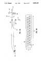
- FIG. 1depicts a typical CE apparatus.
- a high intensity electrical field supplied by high voltage power supply 10is applied across a teflon, glass, or quartz separation capillary tube 12 of narrow inside diameter (5 to 400 micrometers) containing an electrolytic buffer solution.
- the presence of the electrical fieldimparts motion to charged and uncharged moieties present in the buffer through two mechanisms: electro-osmotic (endoosmotic) flow and electrophoretic force.
- Flow of buffer (or sample from sample vial 14) through capillary 12is detected by a detector 16.
- Electro-osmotic flowis the bulk flow of buffer from a first buffer vial 18 to a second buffer vial 19 through capillary 12 due to the shearing movement of a diffuse layer of cations past a more firmly held, dense layer, interacting with integral, anionic groups of the capillary wall.
- Factors which influence the velocity of electroosmotic floware: electrical field strength; buffer dielectric constant; zeta potential (the electrical potential existing between diffuse and compact cationic layers); and buffer viscosity (which is dependent on bulk properties of the buffer and the temperature of the buffer).
- solvents of useare any normally used solvent for standard reverse phase liquid chromatography.
- Electrophoretic forceis the force applied to charged particles residing in an electrical field, and neutral or uncharged molecules are not affected. Positively charged molecules (cations) migrate towards the cathode while negatively charged molecules (anions) move towards the anode.
- Factors controlling solute electrophoretic velocityare: molecular charge; electrical field strength; viscosity of the migration media; and solute molecular geometric factors.
- the net velocity at which a solute travels in an uncoated, open capillary tube during CEis the vector sum of the electro-osmotic and electrophoretic velocities. Buffer viscosity plays a significant role for both of these phenomenon. Both electrophoretic and electro-osmotic velocities are inversely proportional to buffer viscosity, thus affecting the net migration velocity for all solutes.
- solute identityis linked to migration time and velocity.
- CEcapillary zone electrophoresis
- samplesare loaded into the capillary as a slug or plug.
- the lattermay be achieved by application of an electrical field or some hydrodynamic force (vacuum or pressure head).
- An electrical fieldis then applied and the solutes migrate, as bands, down the capillary at their respective net velocities. Differences among these velocities create the primary mechanism for solute separation.
- These solute bandsare then detected by monitoring a bulk property of the buffer such as refractive index, photometric absorbance, fluorescence, electrical conductivity, or thermal conductivity.
- the time period extending from the initiation of the separatory process to the point of solute detectionis termed the migration time.
- the net velocityis determined using the migration time and the distance traveled by the solute.
- a capillary tube 12 as used in an electrophoresis instrumentis supported in a variety of ways, depending on whether tube 12 is to be cooled by air, by liquid, or by metal plates in contact with the capillary tube. Cooling of tube 12 is important since the electrophoresis process subjects the capillary tube to a very high voltage which causes joule heating in the capillary tube. It is important to maintain the temperature of the tube at a stable predetermined temperature so as to be able to make measurements at a known temperature.
- Various schemeshave been suggested for supporting and cooling the capillary tube, all of which have significant disadvantages and many of which are not suitable for air cooling purposes.
- Beam splitter 32 in one form in the prior artis a short length of optical fibers.
- a portion of the light transmitted to some of the optical fibersemerges from the beam splitter 32 at reference arm 34 and is sent via window 36 to a reference photodetector 38 which detects the reference light beam for purposes of comparison.
- the remainder of the light transmitted through beam splitter 32is transmitted through a longer length of optical fibers to sample end 40 of the beam splitter and is focused using a lens 42 into sample cell 44 in which the sample is held.
- the portion of the light which passes through sample cell 44 and the sample thereinis then directed onto a second (sample) photodetector 46 through window 48.
- the first and second photodetectors 38, 46are matched substrate photodetectors, i.e. cut from the same piece of crystal or other photodetecting material, so as to have matching thermal properties. Also shown is monochromator casing 50.
- the dual beam approachcompensates for fluctuations and the changes in intensity of the light source level, as well as any changes in intensity in the propagation of light.
- this prior art systemhas several disadvantages. Since reference photodetector 38 and sample photodetector 46 would be widely separated, they are subject to different amounts of heat due to their different locations. Thereby the problem of dark current i.e., drift caused by unequal heating, is significant, resulting in less precise measurements. Also, if the sample arm 40 of beam splitter 32 (i.e., that portion of the optical path which leads to the sample) is mechanically flexed, this flexing distorts the optical path through the optical fibers in sample arm 40, resulting in more or less light reaching sample cell 44.
- capillary tubesare typically cooled by forced air or circulating liquid or by placing the capillary tube between metal radiator plates.
- the objectis to cool and/or heat the capillary to a particular target temperature.
- the temperature control of the capillary tube in the prior artis performed by monitoring the temperature of the media surrounding the capillary tube. This process is problematic in that a thermal dam occurs at the interface between the media surrounding the capillary tube and the capillary tube itself. That is, thermal transfer is inhibited across this boundary, and therefore the temperature of the media surrounding the capillary tube is not exactly the same as that of the capillary tube itself.
- a non-charged speciesi.e., a neutral species
- a neutral specieswill have no electrophoretic velocity at all and thus can be used to measure the electroosmotic velocity of the system.
- amides or some other neutral speciesare used to measure electro-osmotic velocity.
- These materialsare typically known as neutral markers.
- the term neutral markerrefers to the fact that in the buffer of interest, the neutral marker solute has no electrical charge.
- electro-osmotic flowis determined by introduction of a neutral marker and then observing at one particular wavelength the flow of the neutral marker through the system to identify when the neutral marker passes the detector.
- This processworks well with very simple sample combinations, where no other solutes co-migrate with the neutral marker. If however other compounds present in the sample combination are also neutral, this complicates the process of detecting the neutral marker.
- capillary tubingis coiled and enclosed in an air cooled cartridge.
- the air cooled cartridgeincludes a housing, electrodes fitted to the capillary tubing, and a spherical lens assembly which is part of the optical path.
- the air cooled cartridgeholds the capillary tubing so as to optimize air cooling of the capillary tubing when the cartridge is installed in the instrument.
- the air cooled cartridgefits into a manifold which includes both an anode and a cathode subassembly for holding vials containing the sample or buffer solutions and a ground potential chamber.
- a remote optical pathin which a fiber optic bundle having a particular arrangement of optical fibers for carrying the sample and reference light beams has an extended reference arm for carrying the reference light beam to the reference detector, which is located in close proximity to the sample photodetector.
- the reference photodetectoris in the same environment, i.e., heat level, as is the sample detector.
- the temperature of the capillary tubing during electrophoresisis controlled by observation of the electrical resistance of the capillary tubing.
- This methodrelies on the determination that the electrical resistance of the tubing containing a given buffer is a unique function of its temperature.
- resistancemay be calculated from the observed voltage and current across the capillary, and the capillary tubing may be air cooled by provision of an air flow across the capillary tubing in response to the observed resistance.
- a methodis provided of determining electro-osmotic flow by use of a neutral marker in which the spectral characteristics of the neutral marker are identified and used to determine when the neutral marker has passed the detector.
- the method of observation and determination of the spectrum associated with the neutral markerallows use of determination of electro-osmotic flow even in the case of co-elution or co-migration of a solute which is similar in its electro-phoretical profile to that of the neutral marker.
- FIG. 1shows a prior art electrophoresis apparatus.
- FIG. 2shows a prior art optical path for the UV-visible detector which may be used in the device of FIG. 1.
- FIGS. 3(a) to 3(c)show views of an electrophoresis instrument in accordance with the invention.
- FIG. 3(d)shows schematically a column conditioning and hydrodynamic injection system in accordance with the invention.
- FIG. 4shows an air cooled cartridge in accordance with the invention.
- FIG. 5shows the air cooled cartridge partially inserted into the temperature control system.
- FIGS. 6 and 7show a temperature control system in accordance with the invention.
- FIG. 8shows a manifold in accordance with the invention.
- FIGS. 9(a) to 9(f)show a remote optical path in accordance with the invention.
- FIG. 10shows detail of the fiber optic bundle used in the remote optical path.
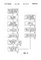
- FIG. 11is a flow chart showing a temperature control method in accordance with the invention.
- FIG. 12shows a calibration plot for temperature control.
- FIG. 13shows a gradient micellular electrophoresis apparatus in accordance with the invention.
- FIG. 14shows detail of the gradient micellular electrophoresis apparatus.
- FIG. 15is a flow chart showing use of a neutral marker in accordance with the invention.
- FIG. 3(b)shows a rear view of the instrument of FIG. 3(a). Shown in enclosure 56 are high voltage power supply 70, high voltage line 72, power transformer 74, vacuum exhaust port 76, oven purge port 78, and helium inlet port 80. The rear of the detector 82 portion of the instrument is shown. Also included are RS232 connector 86, I/O port 88, power switch 90, and voltage selector and fuse block 92.
- FIG. 3(c)shows a front view of the instrument of FIG. 3(a), with the front panel removed. Shown are electric power board 98, a conventional autosampler 100, buffer solution bottle 102, helium valve 104, dessicant bottle 106, waste trap 108, injection vacuum tank 110, pressure transducer 112, vacuum pump 114, fluid pump 116, valve 118, beam splitter 120, optical bench 122, manifold 124, oven (thermal chamber) 126, fan 128, and air cooled cartridge 130.
- electric power board 98Shown are electric power board 98, a conventional autosampler 100, buffer solution bottle 102, helium valve 104, dessicant bottle 106, waste trap 108, injection vacuum tank 110, pressure transducer 112, vacuum pump 114, fluid pump 116, valve 118, beam splitter 120, optical bench 122, manifold 124, oven (thermal chamber) 126, fan 128, and air cooled cartridge 130.
- FIG. 3(d)shows schematically a column conditioning and hydrodynamic injection system for the above described instrument in accordance with the invention. Shown are fluid pump 116, vacuum pump 114, valve VA, valve VB, valve VD, cathode reservoir 136, vent line 138, valve VE, valve VF, valve VC, atmospheric pressure line 140, injection vacuum chamber 110, pressure transducer 112, and control microprocessor 142.
- Cartridge 130consists of: a main body 146; a bobbin assembly 148; a spherical lens holder assembly 150; metallic electrodes 152, 154; electrical contacts 156, 158; and capillary tubing 162 of glass, quartz, or teflon, typically no greater than 500 microns in inside diameter and about 10 to 200 cm. long.
- Main body 146is a support for the other subassemblies. Additionally, main body 146 aligns the electrode 152, 154 and optical 150 subassemblies with their respective counterparts in the manifold and remote optical path (not shown here but described below).
- Bobbin assembly 148supports capillary 162 which is coiled in a concentric circle.
- Bobbin 148consists of a central support ring 166 with radiating capillary support pieces 168, 170, etc.
- Each capillary support piece 168, 170, etc.contains four equally spaced holes (not shown) and one hole centered above the array of four, through which capillary 162 is threaded and held in place. The thickness of each support piece 168, 170 is minimized, maximizing the capillary surface area exposed to ambient air.
- Spherical lens holder 150fastens capillary 162 to the cartridge main body 130 prior to entry of capillary 162 to electrode 152 as well as holding capillary 162 in the proper orientation with spherical lens holder 150, permitting precise image focusing into the capillary lumen, thus limiting stray light.
- Spherical lens holder 150mates with the remainder of the remote optical path (not shown) to provide precise, reproducible optical alignment, as described below.
- Metallic electrodes 152, 154are constructed of high conductivity, low electrochemical reactivity metals. An alloy of platinum-iridium is used in one embodiment. A portion of capillary 162 exits cartridge 130 and enters the manifold (not shown) by passing through the center of electrodes 152, 154. Electrodes 152, 154 each have an inside diameter slightly larger than that of the outside diameter of capillary 162. This minimizes the dead volume between electrodes 152, 154 and capillary 162.
- Air cooled cartridge 130is a structure approximately five inches (12 cm.) wide, nine inches (22 cm.) high, and 0.25 inch (0.5 cm.) thick.
- Main body 146 of the air cooled cartridgeis preferably molded from black delrin. Other low thermal mass, low thermal conductivity, and high dielectric strength materials may be used. The dimensions of air cooled cartridge 130 may be otherwise as convenient.
- Air cooling slots 171-1, 171-2, ..., 171-nare formed in main body 146.
- Spherical lens holder 150is preferably made of black UV stabilized ABS and is a flange-like structure with a smaller portion which fits inside a cavity provided in main body 146 and with a lip for fitting against main body 146 to fix lens holder 150 in place. Other high dielectric strength, UV stable materials may also be used for lens holder 150.
- Bobbin assembly 148around which capillary tube 162 is concentrically wound, is formed of delrin and is about 3.5 inches (9.0 cm.) in diameter and fits inside a cavity provided in main body 146.
- air cooled cartridge 130is partially lowered into a chamber 174 at one side of which is provided a Peltier type heat sink device 176, which is a well known type of solid state device for cooling and/or heating to precise temperatures.
- a Peltier type heat sink device 176On each side of cartridge 130 is an insulative layer of polyethylene 178, 180, each layer 178, 180 approximately 0.78 inches (2.0 cm.) thick. Air cooled cartridge 130 when fully lowered into position between insulative layers 178, 180 is locked in place by a cartridge lock bar 182. A retaining thumb screw 184 is also provided.
- a fan(the blades of which are hidden and not shown) mounted on panel 187 driven by a regulated DC motor 188 fitted with a heat sink assembly 186 for drawing the air cooled by Peltier heat sink 176 across the capillary (not shown) in cartridge 130.
- the cooling system in accordance with the inventionis shown schematically in FIG. 6 showing DC motor 188 for driving fan blades 189, and also installed on panel 187 supporting fan blades 189 is a temperature sensing, resistive thermal device 192 (RTD). As shown, fan blades 189 draw the air (shown by lines) through the center of bobbin 148. The air is then recirculated by fan blades 189 across capillary 162 to the temperature regulating heat exchange surface 197 of the Peltier device.
- RTDtemperature sensing, resistive thermal device
- Peltier device 176is sandwiched between conventional heat exchanging surface 197 and conventional heat dissipating/collecting surface 198.
- Surfaces 197, 198are separated by a 0.25" (6.3 mm) thick layer of polyethylene insulation 199.
- RTD device 192provides a measurement of the temperature of air surrounding capillary 162.
- the capillary electrical resistanceis determined by dividing the applied voltage (usually about 5 KV) by the measured current during a calibration phase.
- This resistance informationis provided to microprocessor 142 which is part of the electrophoresis instrument and which in one embodiment is a Motorola 68008 microprocessor.
- This microprocessoruses the ambient air temperature and capillary resistance data to control the drive current 200 to Peltier device 176 so as to maintain a constant electrical resistance and set point temperature 202 in capillary 162 during the separation process.
- the actual set pointis the capillary resistance.
- Ambient temperature(not shown) is used as a secondary parameter to anticipate the arrival at the desired capillary resistance, thus minimizing set point setting time.
- Manifold 124includes a high potential (anode or cathode) subassembly, including high voltage contact 214, which accepts vials containing either sample solution or buffer solution and also includes a central support subassembly 220, and a ground potential chamber 224, containing high voltage contact 216, which is connected to a valve assembly via port 226 which allows (under automatic control) the filling and flushing with buffer and application of vacuum to the capillary tubing in the air cooled cartridge for the purpose of rinsing, washing, or hydrodynamic injection.
- high potential (anode or cathode) subassemblyincluding high voltage contact 214, which accepts vials containing either sample solution or buffer solution and also includes a central support subassembly 220, and a ground potential chamber 224, containing high voltage contact 216, which is connected to a valve assembly via port 226 which allows (under automatic control) the filling and flushing with buffer and application of vacuum to the capillary tubing
- FIG. 3(d)Also provided in manifold 124 is a hole 230 for the optical bench (not shown, described below) to slide into so as to contact the spherical lens assembly (not shown, in the air cooled cartridge).
- a vial-like chamber 232is built into the manifold structure so as to eliminate the need for a ground potential buffer vial. Also provided are high voltage line entrance 236 and high potential vial holder 238.
- air cooled cartridge 130is marked with a bar code index 246 at a convenient location to identify the particular cassette. Also, additional information is included in bar code index 246.
- This informationincludes the length of capillary tube 162 in that particular air cooled cassette. The length of the tube is required as described above for determining electrical field strength, and electro-osmotic and electrophoretic mobilities and velocities. The length is also required to calculate the fluid-flow resistance in the capillary tube. The fluid-flow resistance is necessary for the system to determine automatically how long it takes for the capillary tube to be flushed with a given solution and what would be the approximate volume of sample loaded into the capillary tube for a given vacuum applied for a given period.
- the systemis automatically informed by reading bar code index 246 of the inside diameter of capillary tube 162. This is necessary for determining the fluid resistance of the capillary tube and the electrical resistance of the capillary tube for the above stated reasons.
- bar code index 246indicates whether the tube is an open capillary tube, i.e. contains no gel, or is a closed tube, i.e. contains gel. This is important for hydrodynamic or vacuum type injections because the gel would be damaged or destroyed by application of a vacuum or hydrodynamic forces. Bar code index 246 also indicates whether the tube has its interior lined with a coating for purposes of knowing whether there is significant electro-osmotic flow in the capillary tube.
- each particular cartridge 130is identified with its own particular number in bar code index 246 so that the system can automatically track the performance of each cartridge and/or capillary tube based on the separation efficiency for a given test.
- Bar code index 246 on air cooled cartridge 130is read in one embodiment of the invention by a conventional bar code reader (not shown) which is part of the electrophoresis instrument.
- the bar code reader in the instrumentreads bar code index 246 on a particular air cooled cartridge and provides the information in the index to the microprocessor and related computer software for the above described purposes.
- the remote optical path as shown schematically in FIG. 9(a)includes a unique fiber optic beam splitter 120 (as in FIG. 3(c)) arrangement for detecting small sample volumes (down to about 100 picoliters) in a capillary.
- Light 260is focused into a fiber optic bundle 262 from the exit slit of a conventional monochromator (including one or two light sources, a shutter, and a diffraction grating as in FIG. 1 and not shown here).
- the monochromatormay be generating light of a given band-width for the purpose of UV-visible photometric absorbance detection, fluorescence detection, refractive index detection, as well as any other means of photometric detection.
- Fiber optic bundle 262may also be focused into fiber optic bundle 262 from a coherent light source (laser) for the purpose of refractive index, fluorescence, thermal-optical-density detection, as well as other means of coherent light photometric detection.
- Fiber optic bundle 262is remotely bifurcated at point 264 into a sample arm 266 and a reference arm 268.
- the light exiting from reference arm 268impinges onto a reference photodetection device 272 located in the same environment as the sample photodetection device 274.
- Light emitting from sample arm 266is focused using a plano-convex lens 276 into a second, spherical lens 280 in direct contact with the capillary 162.
- the fibers of fiber optic sample arm 266may be arranged in cross section in a circle, rectangle, square, trapezoid, or other parallelogram or triangular pattern in order to facilitate the focusing of the image into the center of the capillary.
- Sample photodetector 274is placed directly behind capillary 162.
- the beam splitter housingself-aligns via locating hole 230 in the manifold 124 (see FIG. 8) and on the cartridge lens holder 150 (see FIG. 4).
- Spherical lens 280is thus located in the cartridge lens holder 150, while the plano-convex lens 276, reference photodetector 272, and both ends of the fiber optic bundle 262 are housed in a retractable member (not shown) which slides into and out of the spherical lens holder 150 which is mounted on cartridge 130 (see FIG. 4).
- This structureis advantageous in that remote transference of detection light in the common arm of a bifurcating fiber optic bundle greatly reduces the optical system's sensitivity to mechanical perturbations to the fiber optics.
- light changesare simultaneously viewed by sample 274 and reference photodetectors 272 and are thus correctable.
- Placement of both photodetectors 272, 274 in a similar environmentreduces perturbations resulting from physicomechanical variances in detection environments.
- the combination of lensesproduces an image of appropriate size for small volume detection without any attendant loss of throughput.
- the mechanical layout of the systemis such so that all optical elements are self-aligning.
- FIG. 9(b)shows detail of the optical path at its upper end down to the bifurcation point. Shown are beam splitter body 284, an insert 286 in body 284 to hold the optical fiber bundle 262, the optical fiber exterior PVC monocoil coating 288, PVC shrink tubing 290 over the optical fiber bundle, and a dual plug body 292.
- Optical fiber bundle 262bifurcates into a reference arm connector 296 and sample arm connector 298, both connected mechanically by a connector 300.
- Connector 300is shown in a side view in FIG. 9(c).
- a spacing "d" of about 1.094" (28mm)is provided between the center of the reference arm 268 and sample arm 266.
- the short axis of the sample fiber bundleis parallel to the long axis of the capillary and perpendicular to a horizontal line defined between the center points of the sample and reference arms.
- the above described structureis fastened together with 2039 type epoxy.
- a 360° twistis provided in the fibers in the common sector 288 to increase flexibility.
- the cross-section shape of the sample fiber optic bundle 266may be varied in accordance with the application. For instance, in the case where the light beam in the sample arm is to be transversely focused into a cylinder such as the capillary, it is most desirable to provide a rectangular cross-sectional shape light beam. Thereby the fiber optic bundle is provided in a rectangular or parallelogram shape. In another case when it is desirable to focus the sample light beam into a cylindrical flow cell as in a liquid chromatography detector, then it is desirable to have a circular shape of the cross-section of the light beam and thereby the fiber optics are bundled into a circle in cross-section.
- FIG. 9(e)shows the lower end of the remote optical path, with the beam splitter common trunk 262 bifurcating into the sample arm 266 and reference arm 268, both entering beam splitter block 304.
- Each arm 266, 268is respectively attached to block 304 by a set screw 306, 308.
- the reference photodiode assembly 272is shown, as is lens shroud 310 to carry the sample light beam to the sample cell (not shown).
- Beam splitter block 304is fastened to platform 314, which is attached to support 316 by a set screw 320 and a set of dowels 321 (only one shown).
- FIG. 9(f)Detail of the sample photodiode assembly is shown in FIG. 9(f). Shown are the photodiode housing 322, spring assembly outer ring 324, and spring assembly inner ring 326.
- FIG. 10shows an end-on view of fiber optic bundle 262 showing that the fiber optic bundle 262 is composed of a number of triads of single optic fibers.
- Each triadconsists of one reference type fiber 330 (shown by shading) and two sample type fibers 332, 334 (shown in white).
- the fibersthemselves are identical between the sample and reference fibers.
- the designation of reference or samplemerely indicates to which photodetector the optic fiber directs its light.
- the fiber triadsare arranged in conjunction with each other so as when one moves from one reference plane at the entry portion of the beam splitter to another reference plane the triad is always conserved, so that at any angle the light is introduced to two sample and one reference optic fibers.
- Fiber optic bundle 262 in totalincludes in one embodiment 37 optic fibers.
- the diameter of common fiber optic bundle 262is preferably about 0.067 inches (1.7 mm). This is a matter of design choice, and is not limiting in accordance with the invention. Twice as many sample fibers are provided as reference fibers, since the sample light beam must pass through the capillary tubing and other optics and thus there is more loss of throughput in the sample light beam.
- the fiber optic bundleis custom made.
- the optic fibersare ultraviolet transparent quartz approximately 200 microns in diameter, with a 20 micron thick cladding, and a 12.5 micron thick polyimid coating.
- the optical fibersare 200/220/245 superguide G type.
- the bundleis supported loosely by a 0.125 inch (3.1 mm) inside diameter teflon tube in a PVC monocoil outer jacket.
- the fiber optic bundlein one embodiment is provided by Highlight Fiber Optics in Caldwell, Id.
- the approximate overall length of the beam splitteris 28 inches (70 cm.).
- the point of bifurcation between the sample arm and the reference armis at 26 inches (65 cm.) from the entry portion of the beam splitter.
- constant resistance cooling of the capillaryis provided.
- the electrical resistance of the capillaryprovides a means of sensing the temperature of the capillary. Therefore, a method is provided for measuring and controlling the temperature of the capillary using the apparatus as shown in FIG. 6.
- the electrical resistance of the capillaryis directly proportional to the capillary length and inversely proportional to the capillary radius squared.
- the solution electrical resistanceis inversely proportional to the temperature of the solution and is inversely related to the specific conductivity of the solution in the capillary. This means that for a capillary of a given size and a given length containing a given solution, the electrical resistance is a direct function of the capillary temperature.
- the high voltage power supply's current and voltage conventional sense linesare used to measure the electrical resistance of the capillary, and so in effect the capillary is used as a thermometer.
- a control procedureis provided to control the temperature of the capillary.
- This control procedureis a control program associated with the above-mentioned microprocessor 142 (see FIG. 7) resident in the electrophoresis instrument.
- the procedure for temperature controlis shown in a flow chart in FIG. 11.
- a voltage start slopeis selected at step 340. (See voltage vs. time plot, FIG. 12.) This is the rate (shown by the dotted line in FIG. 12) at which the ultimate separation voltage will be applied. For example, if the electrophoresis separation voltage of 30 KV is achieved in 10 seconds, then the start slope is 3KV/second.
- a set point ambient temperatureis selected at step 342 for the capillary temperature as desired.
- the electrophoresis separation process in the capillarybegins by performing a sample injection and beginning the run by increasing at step 348 both the current and the voltage of the electric power provided to the capillary.
- the current and the voltageare increased at a particular steady rate, equivalent to two times the start slope at step 350.
- Capillary resistanceis calculated during the hold time at step 352 (shown as about 0.8 to 2.4 seconds in FIG. 12) at 5 KV, at which level typically there is no significant joule heating
- the weighted average resistance or average resistance for the calibration period hold timeis calculated. This calculated resistance is then attributed to the resistance of the system at the selected set point temperature.
- the voltage levelis increased to 10 KV at twice the selected start slope in step 356. Then the voltage is further increased to the set voltage at the selected start slope in step 358.
- the next phase in steps 360 to 362is the temperature control phase.
- the resistanceis monitored at step 360 at a particular duty cycle, i.e., for instance 50 times per second, by measuring the capillary current and voltage, and then in step 362 heat is either pumped into or out of the chamber in which the air cooled cartridge is housed by use of the previously described fan and Peltier device.
- the electrical resistance of the capillaryis maintained at a constant level, providing a constant temperature.
- Micellular electrophoretic chromatographyis known in the art. (See Terabe, J. of Microcolumn Techniques, Vol 1, No. 3, 1989, p. 150.) This technique involves formation of a micell in the sample by providing a buffer solution containing amphophilic complexes which bind by non-polar or lipophillic attraction. They remain soluble in aqueous environments due to their polar moieties.
- micellstypically buffer solutions composed of acid or base salts (including but not limited to phosphate, tris, hepes, citrate, borate, amino acids, and other zwitter ionic buffers) in concentrations from 0.01 millimole to 500 millimole are used in con]unction with a detergent or other lipid-like moiety which forms micells.
- the micell producing agentincluding but not limited to sodium dodecylsulfate, bile acids, etc. is added until reaching minimal micell concentration for the given temperature.
- micellular, open tube separationstake advantage of the differences in the partition coefficients of various solutes so that the higher the partition coefficient the longer the solutes stay in contact with the micell under the influence of the electric field in the electrophoresis instrument.
- itis possible to separate neutral compounds on the basis of their partition coefficients.
- a problemarises in trying to separate solutes of similar partition coefficients or whose partition coefficients are so large that they co-migrate on the micells and are never separated.
- the buffer compositionis changed over time and thus because the basic function of the partition coefficient is dependent on the two phases, polar and non-polar components (polar component being the buffer and the non-polar, the micell), the solubility of the solute in the buffer is changed.
- polar componentbeing the buffer and the non-polar, the micell
- solubility of the solute in the bufferis changed.
- those compounds that have slightly lower partition coefficientswill come off the micell.
- the compoundsare selectively removed from the micell as a function of time and thus contact the detector in the instrument and are observed.
- the gradient micellular chromatography apparatusis depicted in FIG. 13.
- a pair of conventional microliter syringe pumps 370, 372are driven at different rates to displace different amounts of fluids which when mixed comprise the buffer.
- Mixingoccurs in a conventional micromixer 376 and the resultant mixture is transported to separation capillary 378 via gradient buffer transfer line 380.
- High voltage electrode 382creates an electric field in separation capillary 378.
- Fluid from the gradient buffer transfer line 380enters separation capillary 378 (see FIG. 14 showing detail of the device of FIG. 13) via electro-osmotic flow (and not parabolic pressure driven flow) as long as the pressure head at point P3 is much greater than that at point P2.
- the excess bufferexits via waste transfer line 386. Sufficient mixing response time is achieved using this split-flow approach.
- microliter pumps 370, 372, micromixer 376 and separation capillary 378are either held at ground potential or enclosed in a Farraday cage 390 to protect against electrical shock.
- gradient micell electrophoresismay also be achieved by temperature programming.
- temperature-entropy productIn thermal gradient micellular capillary electrophoresis, temperature is increased as a function of time. Consequently, the temperature-entropy product also increases. When the temperature-entropy product exceeds the enthalpy of solute-micell binding, the solute is released from the micell and thus migrates at a faster rate to the detector. In order for this process to be used in a reliable, reproducible manner, precise temperature control is required. Such control is possible using the previously described constant resistance cooling technique.
- the user of the instrumentselects a particular neutral marker substance.
- the neutral markeris selected as having a known spectrum and preferably having a spectrum greatly different from those of the solute molecules of interest.
- the selected neutral markeris then injected into the system in step 400 as a single component separation and its spectral characteristics measured.
- particular auto markerssuch as, for example, tryptophan at its pI (isoelectric pH)
- this auto markerwill have an absorbance maximum at approximately 220 nanometers wavelength and a second absorbance maximum at approximately 280 nanometers wavelength as in step 406.
- the systembased on data provided to it, will use the ratio of the absorbance at 220 nanometers to the absorbance at 280 nanometers to provide an identifying value at step 408 for this particular neutral marker.
- the selected neutral markeris then added in the appropriate concentration to the sample in step 410.
- a typical concentrationis 0.1 milligram per milliliter.
- the samples containing the added-in neutral markersare then injected in step 412 into the capillary in the system.
- electrophoresisis conventionally performed.
- the spectrophotometric scanningis performed at step 416 at the two wavelengths of interest, 220 and 280 nanometers.
- all peaks at these wavelengthsare identified. Since other materials in the sample may also give peaks at 220 and 280 nanometers, the ratio of the absorbance at these two wavelengths is used to particularly identify at step 420 by a computer program the particular neutral marker tryptophan selected in the first step 422.
- this particular ratiois detected by the detector in the electrophoresis instrument, this identifies at step 422 the migration time of the neutral marker from the point of sample injection to the detector in the system.
- the entire spectrumis scanned at a number of wavelengths at step 424.
- the systemby means of computer software, constructs at step 426 a three dimensional electropherogram of time versus absorbance versus wavelength.
- This electropherogramis then sliced perpendicular to the temporal, i.e. time axis, and then flipped around. This produces a spectrum of absorbance versus wavelength.
- This methodallows identification of the spectrum associated with a particular neutral marker selected to provide a distinct spectrum.
- the time of detectiondetermines the migration time of that particular neutral marker from the point of injection to the point of detection in the system in step 430.
- This method of scanning all wavelengthsis more precise than the two wavelength method of steps 416 to 422 because it provides a better means of eliminating the problem of co-elution or comigration of solutes which are similar in their electrophoretic profiles to that of the neutral marker.
- the velocity of electro-osmotic flow for both embodiments associated with the systemis then determined by using the above-determined data from the neutral marker in steps 422 or 430. This determination is made in a post-run integration process (not shown). It is well known that electro-osmotic mobility is electro-osmotic velocity divided by electric field strength. Field strength is defined as voltage per column length. The velocity is the distance traveled from the beginning of the capillary at the point of injection to the point of detection of the neutral marker divided by the time required for this movement. Length L is the total length of the column from beginning to end and voltage is the applied voltage. Thus use of the neutral marker in detection hereof as described above allows calculation of the electro-osmotic velocity and of the electro-osmotic mobility.
Landscapes
- Health & Medical Sciences (AREA)
- Life Sciences & Earth Sciences (AREA)
- Molecular Biology (AREA)
- Chemical & Material Sciences (AREA)
- Chemical Kinetics & Catalysis (AREA)
- Electrochemistry (AREA)
- Physics & Mathematics (AREA)
- Analytical Chemistry (AREA)
- Biochemistry (AREA)
- General Health & Medical Sciences (AREA)
- General Physics & Mathematics (AREA)
- Immunology (AREA)
- Pathology (AREA)
- Investigating Or Analysing Materials By Optical Means (AREA)
Abstract
Description
Claims (3)
Priority Applications (1)
| Application Number | Priority Date | Filing Date | Title |
|---|---|---|---|
| US07/470,202US5053115A (en) | 1990-01-25 | 1990-01-25 | Automated neutral marker for capillary electrophoresis |
Applications Claiming Priority (1)
| Application Number | Priority Date | Filing Date | Title |
|---|---|---|---|
| US07/470,202US5053115A (en) | 1990-01-25 | 1990-01-25 | Automated neutral marker for capillary electrophoresis |
Publications (1)
| Publication Number | Publication Date |
|---|---|
| US5053115Atrue US5053115A (en) | 1991-10-01 |
Family
ID=23866656
Family Applications (1)
| Application Number | Title | Priority Date | Filing Date |
|---|---|---|---|
| US07/470,202Expired - Fee RelatedUS5053115A (en) | 1990-01-25 | 1990-01-25 | Automated neutral marker for capillary electrophoresis |
Country Status (1)
| Country | Link |
|---|---|
| US (1) | US5053115A (en) |
Cited By (9)
| Publication number | Priority date | Publication date | Assignee | Title |
|---|---|---|---|---|
| US5302264A (en)* | 1992-09-02 | 1994-04-12 | Scientronix, Inc. | Capillary eletrophoresis method and apparatus |
| US5384024A (en)* | 1992-03-13 | 1995-01-24 | Applied Biosystems, Inc. | Capillary electrophoresis |
| WO1995027198A1 (en)* | 1994-04-04 | 1995-10-12 | Genomyx Corporation | Control of temperature gradients during gel electrophoresis using turbulent coolant gas flow |
| US5736025A (en)* | 1994-04-04 | 1998-04-07 | Genomyx Inc. | Control of temperature gradients during gel electrophoresis using turbulent gas flow |
| US6017496A (en) | 1995-06-07 | 2000-01-25 | Irori | Matrices with memories and uses thereof |
| US6136274A (en)* | 1996-10-07 | 2000-10-24 | Irori | Matrices with memories in automated drug discovery and units therefor |
| US6329139B1 (en) | 1995-04-25 | 2001-12-11 | Discovery Partners International | Automated sorting system for matrices with memory |
| US6416642B1 (en)* | 1999-01-21 | 2002-07-09 | Caliper Technologies Corp. | Method and apparatus for continuous liquid flow in microscale channels using pressure injection, wicking, and electrokinetic injection |
| WO2016065073A1 (en) | 2014-10-22 | 2016-04-28 | Integenx Inc. | Systems and methods for sample preparation, processing and analysis |
Citations (3)
| Publication number | Priority date | Publication date | Assignee | Title |
|---|---|---|---|---|
| US4675300A (en)* | 1985-09-18 | 1987-06-23 | The Board Of Trustees Of The Leland Stanford Junior University | Laser-excitation fluorescence detection electrokinetic separation |
| US4680201A (en)* | 1985-10-30 | 1987-07-14 | Stellan Hjerten | Coating for electrophoresis tube |
| US4705616A (en)* | 1986-09-15 | 1987-11-10 | Sepragen Corporation | Electrophoresis-mass spectrometry probe |
- 1990
- 1990-01-25USUS07/470,202patent/US5053115A/ennot_activeExpired - Fee Related
Patent Citations (3)
| Publication number | Priority date | Publication date | Assignee | Title |
|---|---|---|---|---|
| US4675300A (en)* | 1985-09-18 | 1987-06-23 | The Board Of Trustees Of The Leland Stanford Junior University | Laser-excitation fluorescence detection electrokinetic separation |
| US4680201A (en)* | 1985-10-30 | 1987-07-14 | Stellan Hjerten | Coating for electrophoresis tube |
| US4705616A (en)* | 1986-09-15 | 1987-11-10 | Sepragen Corporation | Electrophoresis-mass spectrometry probe |
Non-Patent Citations (239)
| Title |
|---|
| "40th Anniversary: Pittcon '89 in Atlanta, Unknown, Chimia, vol. 43 (1989), pp. 100-115. |
| "A Rapid Procedure for the Quantitative Analysis of Monoclonal Antibodies by High Performance Capillary Electrophoresis"No Date, Norberto A. Guzman, et al. |
| "Amperometric Detection of Catechols in Capillary Zone Electrophoresis with Normal and Micellar Solutions", Andrew G. Ewing, et al., Analytical Chemistry, vol. 60 (1988), pp. 258-263. |
| "Amperometric Detection of Cateschols in Capillary Zone Electrophoresis with Normal and Micellar Solutions", Andrew G. Ewing, et al., Analytical Chemistry, vol. 60 (1988), pp. 258-263. |
| "Analysis of Peptides Synthezised by Recombinant DNA-Technology Using Capillary Zone Electrophoresis", H. Ludi, et al., Analytica Chimica Acta Accepted, NO DATE Submitted. |
| "Analysis of Peptides Synthezised by Recombinant DNA-Technology Using Capillary Zone Electrophoresis", H. Ludi, et al., Central Anal. Dept. and Biotech. Dept., No Date, Bica-Geigy Ltd., Basel Switzerland, Analytica Chimica Acta Accepted (2 Copies). |
| "Application of Free-Solution Capillary Electrophoresis to the Analytical Scale Separation of Proteins and Peptides", Paul D. Grossman, et al., Analytical Chemistry, vol. 61 (1989), pp. 1186-1194. |
| "Attomole Amino Acid Determination by Capillary Zone Electrophoresis with Thermooptical Absorbance Detection", Norman J. Dovichi, et al., Analytical Chemistry, vol. 61 (1989), pp. 37-40. |
| "Automated Instrumentation for Analytical Capillary Electrophoresis", Robert G. Brownlee and Scott W. Compton, ABL (1988), pp. 10-17. |
| "Automated Instrumentation for Analytical Capillary Electrophoresis", Robert G. Brownlee and Scott W. Compton, Amer. Biotech. Lab., Oct. 1988, Pamphlet. |
| "Band Broadening in Electrokinetic Chromatography with Micellar Solutions and Open-Tubular Capillaries", Shigeru Terabe, et al., Analytical Chemistry, vol. 61 (1989), pp. 251-261. |
| "Bias in Quantitative Capillary Zone Electrophoresis Caused by Electrokinetic Sample Injection", Richard N. Zare et al., Analytical Chemistry, vol. 60 (1988), pp. 375-377. |
| "Capillary Electrophoresis", Andrew G. Ewing, Ross A. Wallingford, and Teresa M. Olefirowicz, Analytical Chemistry, vol. 61 (1989), pp. 292A-303A. |
| "Capillary Electrophoresis", Andrew G. Ewing, Ross A. Wallingford, and Terese M. Olefirowicz, Analytical Chemistry, vol. 61 (1989), pp. 292A-302A. |
| "Capillary Electrophoresis", Richard N. Zare et al., Science, vol. 242 (1988), pp. 224-228. |
| "Capillary Electrophoresis", Richard N. Zare, et al., Science, vol. 242 (1988), pp. 224-228. |
| "Capillary Electrophoresis: A New Era in Microseparations", Norberto A. Gusman et al., Reprinted from Biopharm (1989), Publication. |
| "Capillary Electrophoresis: A New Era in Microseparations", Norberto A. Guzman, et al. (1989), Pamphlet. |
| "Capillary Isotachophoresis/Mass Spectrometry", Richard D. Smith, et al., Analytical Chemistry, vol. 61 (1989), pp. 228-232. |
| "Capillary Zone Electrophoreis and Isotachophoresis as Alternatives to Chromatographic Methods for Purity Control of Synthetic Peptides", Wolfgang Thormann, et al., Journal of Chromatography, vol. 407 (1987), pp. 363-368. |
| "Capillary Zone Electrophoresis for the Determination of Electrophoretic Mobilities and Diffusion Coefficients of Proteins", James W. Jorgenson, et al., J. Microcolumn Separations, vol. 1 (1989), pp. 41-45. |
| "Capillary Zone Electrophoresis of Insulin and Growth Hormone", Randall G. Nielsen, G. Sitta Sittampalam, and Eugene C. Rickard, Analytical Biochemistry, vol. 177 (1989), pp. 20-26. |
| "Capillary Zone Electrophoresis of Proteins in Untreated Fused Silica Tubing", Henk H. Lauer, et al., Analytical Chemistry, vol. 58 (1986), pp. 166-170. |
| "Capillary Zone Electrophoresis Quantitative Study of the Effects of Some Dispersive Processes on the Separation Efficiency", P. Bocek et al., Journal of Chromatography, vol. 452 (1988), pp. 601-613. |
| "Capillary Zone Electrophoresis with Electrochemical Detection in 12.7 μm Diameter Columns", Andrew G. Ewing, et al., Analytical Chemistry, vol. 60 (1988), pp. 1972-1975. |
| "Capillary Zone Electrophoresis with Electrochemical Detection", Andrew G. Ewing et al., Analytical Chemistry, vol. 59 (1987), pp. 1762-1766. |
| "Capillary Zone Electrophoresis with Electrochemical Detection", Andrew G. Ewing, et al., Analytical Chemistry, vol. 59 (1987), pp. 1762-1766. |
| "Capillary Zone Electrophoresis", James W. Jorgenson and Krynn DeArman Lukacs, Science, vol. 222 (1983), pp. 266-272. |
| "Capillary Zone Electrophoresis", James W. Jorgenson et al., Science, vol. 222 (1983), pp. 266-272. |
| "Capillary Zone Electrophoresis", W. Th. Kok and G. J. M. Bruin, European Chrom. News, vol. 2 (1989), pp. 22-36. |
| "Capillary Zone Electrophoresis: Effect of Physical Parameters on Separation Efficiency and Quantitation", J. W. Jorgenson, et al., Journal of High Resolution Chromatography & Chromatography Comm., vol. 8 (1985), pp. 407-411. |
| "Capillary Zone Electrophoresis-Mass Spectrometry Using an Electrospray Ionization Interface", Richard D. Smith, et al., Analytical Chemistry, vol. 60 (1988), pp. 436-441. |
| "Capillary Zone Electrophoretic Separation of Peptides and Proteins Using Low pH Buffers in Modified Silica Capillaries", Randy M. McCormick, Analytical Chemistry, vol. 60 (1988), pp. 2322-2328. |
| "Capillary Zone Electrophoretic Separations of Proteins in Polyethylene Glycol-Modified Capillaries", H. Poppe, et al., Journal of Chromatography, vol. 471 (1989), pp. 429-436. |
| "Carrier Free Zone Electrophoresis, Displacement Electrophoresis and Isoelectric Focusing in a High-Performance Electrophoresis Apparatus", S. Hjerten, et al., Journal of Chromatography, vol. 403 (1987), pp. 47-61. |
| "Characterization and Automation of Sample Introduction Methods for Capillary Zone Electrophoresis", James W. Jorgenson et al. Analytical Chemistry, vol. 60 (1988), pp. 642-648. |
| "Characterization and Automation of Sample Introduction Methods for Capillary Zone Electrophoresis", James W. Jorgenson, et al., Analytical Chemistry, vol. 60 (1988), pp. 642-648. |
| "Characterization of a Microinjector for Capillary Zone Elecrophoresis", Andrew G. Ewing, et al., Analytical Chemistry, vol. 59 (1987), pp. 678-681. |
| "Characterization of a Microinjector for Capillary Zone Electrophoresis", Andrew G. Ewing et al., Analytical Chemistry, vol. 59 (1987), pp. 678-681. |
| "Current-Monitoring Method for Measuring the Electroosmotic Flow Rate in Capillary Zone Electrophoresis", Richard N. Zare, et al., Analytical Chemistry, vol. 60 (1988), pp. 1837-1838. |
| "Determination of Alkaloids of Fumaria Parviflora and Fumaria Capreolata by High-Performance Liquid Chromatography and Capillary Isotachophoresis", Vilim Simanek, et al., Journal of Chromatography, vol. 445 (1988), pp. 258-263. |
| "Determination of Methotrexate and its Major Metabolite, 7-Hydroxymethotrexate, Using Capillary Zone Electrophoresis and Laser-Induced Fluorescence Detection", Richard N. Zare, et al., Journal of Chromatography, vol. 426 (1988), pp. 129-140. |
| "Effect of Addition of Organic Solvent on the Separation of Positional Isomers in High-Voltage Capillary Zone Electrophoresis", Susumu Honda et al., Analytical Chemistry, vol. 59 (1987), pp. 487-490. |
| "Effect of Buffer pH and Peptide Composition of the Selectivity of Peptide Separations by Capillary Zone Electrophoresis", Paul D. Grossman, Henk H. Lauer, et al., Analytical Biochemistry, vol. 173 (1988), pp. 265-270. |
| "Effect of Temperature Gradients on the Efficiency of Capillary Zone Electrophoresis Separations", Eli Grushka et al., Analytical Chemistry, vol. 61 (1989), pp. 241-246. |
| "Effects of Methanol-Modified Mobile Phase on the Separation of Isotopically Substituted Compounds by Micellar Electrokinetic Capillary Chromatography", James W. Jorgenson et al., J. Microcolumn Separations, (1989), vol. 1, pp. 125-130. |
| "Effects of pH on Electrokinetic Velocities in Micellar Electrokinetic Chromatography", Koji Otsuka et al., J. Microcolumn Separations, vol. 1 (1989), pp. 150-154. |
| "Electric Sample Splitter for Capillary Zone Electrophoresis", P. Bocek et al., Journal of Chromatography, vol. 320 (1985), pp. 159-165. |
| "Electrokinetic Resolution of Amino Acid Enantiomers with Copper (II)-Aspartame Support Electrolyte", Richard N. Zare, et al., Analytical Chemistry, vol. 59 (1987), pp. 44-49. |
| "Electrokinetic Separation Methods", Carel J. Van Oss, Dept. of Microbiology, State University, Buffalo, N.Y. vol. 8(2) (1979), pp. 119-198. |
| "Electrophoresis", James W. Jorgenson, Analytical Chemistry, vol. 58 (1986), pp. 743A-760A. |
| "Eliminating Effects of Electrical Discharge is Key to Fast, Reliable Signal Transmission", Louis G. Galambos, Elect. Prod., Military Special (1989), pp. 47-48. |
| "Evaluation of an Automatic Siphonic Sampler for Capillary Zone Electrophoresis", Susumu Honda et al., Journal of Chromatography, vol. 404 (1987), pp. 313-320. |
| "Evaluation of an Automatic Siphonic Sampler for Capillary Zone Electrophoresis", Susumu Honda, et al., Journal of Chromatography, vol. 404 (1987), pp. 313-320. |
| "Factors Affecting Plate Height in High Performance Zonal Capillary Electrophoreses (HPZCE)", No Date, S. A. Swedberg, et al. |
| "First International Symposium on High Performance Capillary Electrophoresis", Stephen L. Pentoney, Jr., et al., Poster, TP-125 (1989), Boston, Mass. |
| "Fluorescence Lifetime Filtering", Linda B. McGowan, Analytical Chemistry, vol. 61 (1989), pp. 839A-847A. |
| "Fluorescence-Detected Circular Dichroism for On-Column Detection in Capillary Electrophoresis", Edward S. Yeung, et al., Analytical Chemistry, vol. 61 (1989), pp. 1344-1347. |
| "Flurometric Photodiode Array Detection in Capillary Electrophoresis", Michael J. Sepaniak, et al., J. Microcolumn Separations, vol. 1 (1981), pp. 155-157. |
| "Focusing Counterparts of Electrical Field Flow Fractionation and Capillary Zone Electrophoresis Electrical Hyperlayer Field Flow Fractionation and Capillary Isoelectric Focusing", Wolfgang Thormann et al., Journal of Chromatography, vol. 461 (1989), pp. 95-101. |
| "Fraction Collector for Capillary Zone Electrophoresis", James W. Jorgenson et al., Journal of Chromatography, vol. 438 (1988), pp. 23-34. |
| "Fraction Collector for Capillary Zone Electrophoresis", James W. Jorgenson, et al., Journal of Chromatography, vol. 438 (1988), pp. 23-34. |
| "Free-Zone Electrophoresis in Glass Capillaries", James W. Jorgenson and Krynn DeArman Lukacs, Clinical Chemistry, vol. 27 (1981), pp. 1551-1553. |
| "Gradient Elution for Micellar Electrokinetic Capillary Chromatography", Michael J. Sepaniak, et al., Analytical Chemistry, vol. 60 (1988), pp. 617-621. |
| "Growth of Colloidal Particles in an Electrokinetic Separation Technique", B. K. Mishra et al., Separation Science and Tech., vol. 24 (1989), pp. 247-252. |
| "High Performance Capillary Gel Electrophoresis: High Resolutuion and Micropreparative Applications", B. L. Karger, et al., Topic 3, Abstract, No Date, Submitted, pp. 151-159. |
| "High Performance Capillary Gell Electrophoresis: High Resolution and Micropreparative Applications", No Date, B. L. Karger, et al. |
| "High Precision Laser-Based Refractive Index Determination Within Picoliter Volumes Using Flow-Modification of the Sheath Flow Cuvette", Norman J. Dovichi, et al., Can. J. Spectro, No Date, Abstract Submitted. |
| "High Speed Capillary Zone Electrophoresis with Laser Induced Fluorescence Detection", J. W. Jorgenson, et al., Journal of High Resolution Chromatography & Chromatography Comm., vol. 11 (1988), pp. 533-535. |
| "High Voltage Capillary Zone Electrophoresis: Operating Parameters Effects on Electroendosmotic Flows and Electrophoretic Mobilities", K. D. Altria/C. F. Simpson, Chromatographia, vol. 24 (1987), pp. 527-532. |
| "High-Performance Capillary Electrophoresis Using Open Tubes and Gels", B. K. Karger et al., Chromatographia, vol. 24 (1987), pp. 15-24. |
| "High-Performance Capillary Electrophoresis Using Open Tubes and Gels", B. L. Karger et al., Chromatographia, vol. 24 (1987), pp. 15-24. |
| "High-Performance Capillary Electrophoresis Using Open Tubes and Gels", B. L. Karger, et al., Chromatographia, vol. 24 (1987), pp.15-24. |
| "High-Performance Capillary Electrophoretic Separation of Bases, Nucleosides, and Oligonucleotides: Retention Manipulation via Micellar Solutions and Metal Additives", B. L. Karger et al. Analytical Chemistry, vol. 59 (1987), pp. 1021-1027. |
| "High-Performance Electrophoresis Elimination of Electroendosmosis and Solute Adsorption", Stellan Hjerten, Journal of Chromatography, vol. 347 (1985), pp. 191-198. |
| "High-Performance Sodium Dodecyl Sulfate Polyacrylamide Gel Capillary Electrophoresis of Peptides and Proteins", B. L. Karger et al., Journal of Chromatography, vol. 397 (1987), pp. 409-417. |
| "High-Performance Sodium Dodecyl Sulfate Polyacrylamide Gel Capillary Electrophoresis of Peptides and Proteins", B. L. Karger, et al., Journal of Chromatography, vol. 397 (1987), pp. 409-417. |
| "High-Speed Micellar Electrokinetic Capillary Chromatography of the Common Phosphorylated Nucleosides", Milos Novotny, et al., J. Microcolumn Separations, vol. 1 (1989), pp. 136-141. |
| "Improved Electrospray Ionization Interface for Capillary Zone Electrophoresis-Mass Spectrometry", Richard D. Smith, et al., Analytical Chemistry, vol. 60 (1988), pp. 1948-1952. |
| "Improved Resolution in Capillary Zone Electrophoresis: Analysis of Factors Influencing Peak Broadening", Xiaohua Huang, William F. Coleman, Richard N. Zare, Department of Chemistry, no date, Stanford University, Calif., submitted. |
| "Isotachophoresis as a Preseparation Technique for Liquid Chromatography", A. C. Schoots, et al., Journal of Chromatography, vol. 277 (1983), pp. 328-332. |
| "Laser Fluorometric Detection of Porphyrin Methyl Esters for High-Performance Thin-Layer Chromatography", Carmen W. Huie et al., Analytical Chemistry, vol. 61 (1989), pp. 2288-2292. |
| "Mass-Action Model of Mixed Micellization", E. I. Franses et al., Journal of Physical Chemistry, vol. 88 (1984), pp. 1642-1648. |
| "Micellar, Inclusion and Metal-Complex Enantioselective Pseudophases in High-Performance Electromigration Methods", Eva Smolkova-Keulemansova, et al., Journal of Chromatography, vol. 452 (1988), pp. 571-590. |
| "Modification of Electroosmotic Flow with Cetyltrimethylammonium Bromide In Capillary Zone Electrophoresis", T. Tsuda, Journal of High Resolution Chromatography & Chromatography Comm., vol. 10 (1987), pp. 622-625. |
| "Neochromatographic Technologies: 1. Capillary Electrophoresis", Unknown, Chimia, vol. 43 (1989), pp. 134-141. |
| "Nonideal Multicomponent Mixed Micelle Model", P. M. Holland et al., Journal of Physical Chemistry, vol. 87 (1983), pp. 1984-1990. |
| "On Line Radioisotope Detector for Capillary Electrophoresis", Richard N. Zare et al., Department of Chemistry, Stanford University, Submitted. |
| "On-Column Capillary Microbore Flow Cell for Chromatographic Applications Utilizing Optical Waveguides: An Improved Design Based on Theoretical Considerations", Alfredo E. Bruno, et al., Central Anal. Dept., Ciba Geigy Ltd., CH-4002 Basel, Switzerland, Analytica Chimica Acta, Submitted, Sep. 1988. |
| "On-Column Conductivity Detector for Capillary Zone Electrophoresis", Richard N. Zare et al., Analytical Chemistry, vol. 59 (1987), pp. 2747-2749. |
| "On-Column Conductivity Detector for Capillary Zone Electrophoresis", Richard N. Zare, et al., Analytical Chemistry, vol. 59 (1987), pp. 2747-2749. |
| "On-Column UV Absorption Detector for Open Tubular Capillary Zone Electrophoresis", James W. Jorgenson et al., Journal of Chromatography, vol. 315 (1984), pp. 135-143. |
| "On-Column UV Absorption Detector for Open Tubular Capillary Zone Electrophoresis", James W. Jorgenson, et al., Journal of Chromatography, vol. 315 (1984), pp. 135-143. |
| "On-Line Capillary Zone Electrophoresis-Ion Spray Tandem Mass Spectrometry for the Determination of Dynorphins", Wolfgand Muck, Jack D. Henion, et al., Journal of Chromatography, vol. 458 (1988), pp. 313-321. |
| "On-Line Connector for Microcolumns: Application to the On-Column o-Phthaldialdehyde Derivatization of Amino Acids Separated by Capillary Zone Electrophoresis", Richard N. Zare, et al., Analytical Chemistry, vol. 60 (1988), pp. 2625-2629. |
| "On-Line Connector for Microcolumns: Application to the On-Line o-Phthaldialdehyde Derivatization of Amino Acids Separated by Capillary Zone Electrophoresis", Richard N. Zare et al., Analytical Chemistry, vol. 60 (1988), pp. 2625-2629. |
| "On-Line Fiber Optic UV Detection Cell and Conductivity Cell for Capillary Zone Electrophoresis", Frantisek Foret et al., Electrophoresis, vol. 7 (1986), pp. 430-432 and Analytical Chemistry, vol. 59 (1987), p. 2749. |
| "On-Line Fiber Optic UV Detection Cell and Conductivity Cell for Capillary Zone Electrophoresis", Frantisek Foret, et al., Electrophoresis, vol. 7 (1986), pp. 430-432. |
| "On-Line Mass Spectrometric Detection for Capillary Zone Electrophoresis", Richard D. Smith, et al., Analytical Chemistry, vol. 59 (1987), pp. 1230-1232. |
| "On-Line Radioisotope Detector for Capillary Electrophoresis", Richard N. Zare, et al., Dept. of Chemistry, No Date, Stanford University, Calif. Abstract, Submitted, pp. 1-25. |
| "Optical Microscope Observations of Electrokinetic Separation in Solvent-Refined Coal", Neville C. Lockhart and Joseph W. Snaith, Fuel, vol. 59 (1980), pp. 389-396. |
| "Optimization of Sensitivity and Separation in Capillary Zone Electrophoresis with Indirect Fluorescence Detection", Edward S. Yeung, et al., Analytical Chemistry, vol. 60 (1988), pp. 2642-2646. |
| "Post-Capillary Fluorescence Detection in Capillary Zone Electrophoresis Using o-Phthaldialdehyde", James W. Jorenson, et al., Journal of Chromatography, vol. 447 (1988), pp. 117-131. |
| "Post-Column Detection for Capillary Zone Electrophoresis", Takao Tsuda, et al., Journal of Chromatography, vol. 456 (1988), pp. 375-381. |
| "Qualitative Characteristics of Capillary Isotachophoresis Identification of Isotachophoretic Zones", (1982) Frans Everaerts, Jetse Reijenga, et al. |
| "Quantitation of LI+ In Serum by Capillary Zone Electrophoresis with an On-Column Conductivity Detector", Richard N. Zare, et al., Journal of Chromatography, vol. 425 (1988), pp. 385-390. |
| "Quantitative Analysis of Low Molecular Weight Carboxylic Acids by Capillary Zone Electrophoresis/Conductivity Detection", Richard N. Zare, et al., Analytical Chemistry, vol. 61 (1989), pp. 766-770. |
| "Raman Spectroscopic Detection System for Capillary Zone Electrophoresis", Michael D. Morris, et al., App. Spectro., vol. 42 (1988), pp. 515-518. |
| "Random-Walk Theory of Nonequilibrium Plate Height in Micellar Electrokinetic Capillary Chromatography", Unknown, Analytical Chemistry, vol 61 (1989), pp. 2455-2461. |
| "Retention of Catechols in Capillary Electrophoresis with Micellar and Mixed Micellar Solutions", Andrew G. Ewing et al., J. Microcolumn Separations, vol. 1 (1989), pp. 23-27. |
| "Retention of Ionic and Non-Ionic Catechols in Capillary Zone Electrophoresis with Micellar Solutions", Andrew G. Ewing, et al., Journal of Chromatography, vol. 441 (1988), pp. 299-309. |
| "Rotary-Type Injector for Capillary Zone Electrophoresis", Takao Tsuda et al., Analytical Chemistry, vol. 59 (1987), pp. 799-800. |
| "Rotary-Type Injector for Capillary Zone Electrophoresis", Takao Tsuda, et al., Analytical Chemistry, vol. 59 (1987), pp. 799-800. |
| "Separation of Modified Nucleic Acid Constituents By Micellar Electrokinetic Capillary Chromatography", Wayne H. Griest et al., Journal of Chromatography, vol. 409 (1987), pp. 192-203. |
| "Separation of Oxygen Isotopic Benzoic Acids by Capillary Zone Electrophoresis Based on Isotope Effects on the Dissociation of the Carboxyl Group", Shigeru Terabe, et al., Analytical Chemistry, vol. 60 (1988), pp. 1673-1677. |
| "Separation of Serotonin from Catechols by Capillary Zone Electrophoresis with Electrochemical Detection", Andrew G. Ewing et al., Analytical Chemistry, vol. 61 (1989), pp. 98-100. |
| "Simple Sampling Device for Capillary Isotachophoresis and Capillary Zone Electrophoresis", F. M. Everaerts et al., Journal of Chromatography, vol. 452 (1988), pp. 615-622. |
| "Simple Sampling Device for Capillary Isotachophoresis and Capillary Zone Electrophoresis", F. M. Everaerts, et al., Journal of Chromatography, vol. 452 (1988), pp. 615-622. |
| "Simultaneous Determination of Iodate and Periodate by Capillary Zone Electrophoresis: Application to Carbohydrate Analysis", Susumu Honda, Analytical Biochemistry, vol. 177 (1989), pp. 62-66. |
| "Simultaneous Determination of Reducing Monosaccharides by Capillary Zone Electrophoresis as the Borate Complexes of N-2-Pyridylglycamines", Susumu Honda, Shigefumi Iwase, Akiko Makino et al., Analytical Biochemistry, vol. 176 (1989), pp. 72-77. |
| "Stationary Phase Solvation in Capillary Supercritical Fluid Chromatography", Clement R. Yonker, et al., Analytical Chemistry, vol. 61 (1989), pp. 1348-1353. |
| "Subattomole Amino Acid Analysis by Capillary Zone Electrophoresis and Laser-Induced Fluorescence", Norman J. Dovichi, et al., Science, vol. 242 (1988), pp. 562-564. |
| "Theoretical and Experimental Separation Dynamics in Capillary Zone Electrophoresis", Wolfgang Thormann, Jon-Pierre Michaud, et al., Analytical Electro., No Date, pp. 267-270. |
| "Theoretical Consideration on the Desgin of Cyclindric Flow Cells Utilizing Optical Fibers", Alfredo E. Bruno, et al., Central Analytical Dept., No Date, Ciba-Geigy Ltd., Basel. |
| "Theoretical Considerations for Zone Electrophoretic Sample Treatment in Liquid Chromatography", W. Th. Kok, Chromatographia, vol. 24 (1987), pp. 442-448. |
| "Ultramicro Amino Acid Analysis: Ranging Below Attomoles", Norman J. Dovichi and Yung Fong Cheng, Circle Reader Service Card, No. 67 (1989), pp. 10-14. |
| "Use of Complexing Agents for Selective Separation in High-Performance Capillary Electrophoresis Chiral Resolution Via Cyclodextrins Incorporated Within Polyacrylamide Gel Columns", N. Grinberg, B. L. Karger et al., Journal of Chromatography, vol. 440 (1988), pp. 41-52. |
| "Use of Complexing Agents for Selective Separation in High-Performance Capillary Electrophoresis Chiral Resolution Via Cyclodextrins Incorporated Within Polyacrylamide Gel Columns", N. Grinberg, B. L. Karger, et al., Journal of Chromatography, vol. 446 (1986), pp. 41-53. |
| "Use of Complexing Agents for Selective Separation in High-Performance Capillary Electrophoresis Chiral Resolution Via Cyclodextrins Incorporated within Polyacrylamide Gel Columns", N. Grinberg, B. L. Karger, et al., Journal of Chromatography, vol. 448 (1988), pp. 41-53. |
| "Use of Double-Detector System for the Measurement of Mobilities in Zone Electrophoresis", F. M. Everaerts, et al., Journal of Chromatography, vol. 452 (1988), pp. 591-600. |
| "Use of Oxiranes in the Preparation of Bonded Phase Supports", Shung Ho Chang, et al., Journal of Chromatography, vol. 120 (1976), pp. 321-333. |
| "Variable Wavelength On-Column Fluorescence Detector for Open-Tubular Zone Electrophoresis", James W. Jorgenson, et al., Journal of Chromatography, vol. 352 (1986), pp. 337-343. |
| "Variable-Wavelength On-Column Fluorescence Detector for Open-Tubular Zone Electrophoresis", James W. Jorgenson et al., Journal of Chromatography, vol. 352 (1986), pp. 337-343. |
| "Visible Semiconductor Laser Fluorometry", Nobuhiko Ishibashi et al., Analytical Chemistry, vol. 61 (1989), pp. 2285-2288. |
| "Zone Broadening Due to Sample Injection in Capillary Zone Electrophoresis", Eli Grushka et al., Journal of Chromatography, vol. 471 (1989), pp. 421-428. |
| "Zone Electrophoresis in Open-Tubular Capillaries-Recent Advances", H. H. Lauer and D. McManigill, Trends in Analytical Chemistry, vol. 5 (1986), pp. 11-15. |
| 40th Anniversary: Pittcon 89 in Atlanta, Unknown, Chimia, vol. 43 (1989), pp. 100 115.* |
| Amperometric Detection of Cateschols in Capillary Zone Electrophoresis with Normal and Micellar Solutions , Andrew G. Ewing, et al., Analytical Chemistry, vol. 60 (1988), pp. 258 263.* |
| Analysis of Peptides Synthezised by Recombinant DNA Technology Using Capillary Zone Electrophoresis , H. Ludi, et al., Analytica Chimica Acta Accepted, NO DATE Submitted.* |
| Analysis of Peptides Synthezised by Recombinant DNA Technology Using Capillary Zone Electrophoresis , H. Ludi, et al., Central Anal. Dept. and Biotech. Dept., No Date, Bica Geigy Ltd., Basel Switzerland, Analytica Chimica Acta Accepted (2 Copies).* |
| Application of Free Solution Capillary Electrophoresis to the Analytical Scale Separation of Proteins and Peptides , Paul D. Grossman, et al., Analytical Chemistry, vol. 61 (1989), pp. 1186 1194.* |
| Attomole Amino Acid Determination by Capillary Zone Electrophoresis with Thermooptical Absorbance Detection , Norman J. Dovichi, et al., Analytical Chemistry, vol. 61 (1989), pp. 37 40.* |
| Automated Instrumentation for Analytical Capillary Electrophoresis , Robert G. Brownlee and Scott W. Compton, ABL (1988), pp. 10 17.* |
| Automated Instrumentation for Analytical Capillary Electrophoresis , Robert G. Brownlee and Scott W. Compton, Amer. Biotech. Lab., Oct. 1988, Pamphlet.* |
| Bias in Quantitative Capillary Zone Electrophoresis Caused by Electrokinetic Sample Injection , Richard N. Zare et al., Analytical Chemistry, vol. 60 (1988), pp. 375 377.* |
| Capillary Electrophoresis , Andrew G. Ewing, Ross A. Wallingford, and Terese M. Olefirowicz, Analytical Chemistry, vol. 61 (1989), pp. 292A 302A.* |
| Capillary Electrophoresis , Richard N. Zare et al., Science, vol. 242 (1988), pp. 224 228.* |
| Capillary Electrophoresis: A New Era in Microseparations , Norberto A. Gusman et al., Reprinted from Biopharm (1989), Publication.* |
| Capillary Electrophoresis: A New Era in Microseparations , Norberto A. Guzman, et al. (1989), Pamphlet.* |
| Capillary Isotachophoresis/Mass Spectrometry , Richard D. Smith, et al., Analytical Chemistry, vol. 61 (1989), pp. 228 232.* |
| Capillary Zone Electrophoreis and Isotachophoresis as Alternatives to Chromatographic Methods for Purity Control of Synthetic Peptides , Wolfgang Thormann, et al., Journal of Chromatography, vol. 407 (1987), pp. 363 368.* |
| Capillary Zone Electrophoresis , James W. Jorgenson and Krynn DeArman Lukacs, Science, vol. 222 (1983), pp. 266 272.* |
| Capillary Zone Electrophoresis , James W. Jorgenson et al., Science, vol. 222 (1983), pp. 266 272.* |
| Capillary Zone Electrophoresis , W. Th. Kok and G. J. M. Bruin, European Chrom. News, vol. 2 (1989), pp. 22 36.* |
| Capillary Zone Electrophoresis for the Determination of Electrophoretic Mobilities and Diffusion Coefficients of Proteins , James W. Jorgenson, et al., J. Microcolumn Separations, vol. 1 (1989), pp. 41 45.* |
| Capillary Zone Electrophoresis of Insulin and Growth Hormone , Randall G. Nielsen, G. Sitta Sittampalam, and Eugene C. Rickard, Analytical Biochemistry, vol. 177 (1989), pp. 20 26.* |
| Capillary Zone Electrophoresis of Proteins in Untreated Fused Silica Tubing , Henk H. Lauer, et al., Analytical Chemistry, vol. 58 (1986), pp. 166 170.* |
| Capillary Zone Electrophoresis Quantitative Study of the Effects of Some Dispersive Processes on the Separation Efficiency , P. Bocek et al., Journal of Chromatography, vol. 452 (1988), pp. 601 613.* |
| Capillary Zone Electrophoresis with Electrochemical Detection , Andrew G. Ewing et al., Analytical Chemistry, vol. 59 (1987), pp. 1762 1766.* |
| Capillary Zone Electrophoresis with Electrochemical Detection , Andrew G. Ewing, et al., Analytical Chemistry, vol. 59 (1987), pp. 1762 1766.* |
| Capillary Zone Electrophoretic Separation of Peptides and Proteins Using Low pH Buffers in Modified Silica Capillaries , Randy M. McCormick, Analytical Chemistry, vol. 60 (1988), pp. 2322 2328.* |
| Capillary Zone Electrophoretic Separations of Proteins in Polyethylene Glycol Modified Capillaries , H. Poppe, et al., Journal of Chromatography, vol. 471 (1989), pp. 429 436.* |
| Carrier Free Zone Electrophoresis, Displacement Electrophoresis and Isoelectric Focusing in a High Performance Electrophoresis Apparatus , S. Hjerten, et al., Journal of Chromatography, vol. 403 (1987), pp. 47 61.* |
| Characterization and Automation of Sample Introduction Methods for Capillary Zone Electrophoresis , James W. Jorgenson et al. Analytical Chemistry, vol. 60 (1988), pp. 642 648.* |
| Characterization of a Microinjector for Capillary Zone Electrophoresis , Andrew G. Ewing et al., Analytical Chemistry, vol. 59 (1987), pp. 678 681.* |
| Current Monitoring Method for Measuring the Electroosmotic Flow Rate in Capillary Zone Electrophoresis , Richard N. Zare, et al., Analytical Chemistry, vol. 60 (1988), pp. 1837 1838.* |
| Determination of Alkaloids of Fumaria Parviflora and Fumaria Capreolata by High Performance Liquid Chromatography and Capillary Isotachophoresis , Vilim Simanek, et al., Journal of Chromatography, vol. 445 (1988), pp. 258 263.* |
| Determination of Methotrexate and its Major Metabolite, 7 Hydroxymethotrexate, Using Capillary Zone Electrophoresis and Laser Induced Fluorescence Detection , Richard N. Zare, et al., Journal of Chromatography, vol. 426 (1988), pp. 129 140.* |
| Effect of Addition of Organic Solvent on the Separation of Positional Isomers in High Voltage Capillary Zone Electrophoresis , Susumu Honda et al., Analytical Chemistry, vol. 59 (1987), pp. 487 490.* |
| Effect of Buffer pH and Peptide Composition of the Selectivity of Peptide Separations by Capillary Zone Electrophoresis , Paul D. Grossman, Henk H. Lauer, et al., Analytical Biochemistry, vol. 173 (1988), pp. 265 270.* |
| Effect of Temperature Gradients on the Efficiency of Capillary Zone Electrophoresis Separations , Eli Grushka et al., Analytical Chemistry, vol. 61 (1989), pp. 241 246.* |
| Effects of Methanol Modified Mobile Phase on the Separation of Isotopically Substituted Compounds by Micellar Electrokinetic Capillary Chromatography , James W. Jorgenson et al., J. Microcolumn Separations, (1989), vol. 1, pp. 125 130.* |
| Effects of pH on Electrokinetic Velocities in Micellar Electrokinetic Chromatography , Koji Otsuka et al., J. Microcolumn Separations, vol. 1 (1989), pp. 150 154.* |
| Electric Sample Splitter for Capillary Zone Electrophoresis , P. Bocek et al., Journal of Chromatography, vol. 320 (1985), pp. 159 165.* |
| Electrokinetic Resolution of Amino Acid Enantiomers with Copper (II) Aspartame Support Electrolyte , Richard N. Zare, et al., Analytical Chemistry, vol. 59 (1987), pp. 44 49.* |
| Electrophoresis , James W. Jorgenson, Analytical Chemistry, vol. 58 (1986), pp. 743A 760A.* |
| Eliminating Effects of Electrical Discharge is Key to Fast, Reliable Signal Transmission , Louis G. Galambos, Elect. Prod., Military Special (1989), pp. 47 48.* |
| Evaluation of an Automatic Siphonic Sampler for Capillary Zone Electrophoresis , Susumu Honda et al., Journal of Chromatography, vol. 404 (1987), pp. 313 320.* |
| First International Symposium on High Performance Capillary Electrophoresis , Stephen L. Pentoney, Jr., et al., Poster, TP 125 (1989), Boston, Mass.* |
| Fluorescence Lifetime Filtering , Linda B. McGowan, Analytical Chemistry, vol. 61 (1989), pp. 839A 847A.* |
| Flurometric Photodiode Array Detection in Capillary Electrophoresis , Michael J. Sepaniak, et al., J. Microcolumn Separations, vol. 1 (1981), pp. 155 157.* |
| Focusing Counterparts of Electrical Field Flow Fractionation and Capillary Zone Electrophoresis Electrical Hyperlayer Field Flow Fractionation and Capillary Isoelectric Focusing , Wolfgang Thormann et al., Journal of Chromatography, vol. 461 (1989), pp. 95 101.* |
| Fraction Collector for Capillary Zone Electrophoresis , James W. Jorgenson et al., Journal of Chromatography, vol. 438 (1988), pp. 23 34.* |
| Free Zone Electrophoresis in Glass Capillaries , James W. Jorgenson and Krynn DeArman Lukacs, Clinical Chemistry, vol. 27 (1981), pp. 1551 1553.* |
| Gradient Elution for Micellar Electrokinetic Capillary Chromatography , Michael J. Sepaniak, et al., Analytical Chemistry, vol. 60 (1988), pp. 617 621.* |
| Growth of Colloidal Particles in an Electrokinetic Separation Technique , B. K. Mishra et al., Separation Science and Tech., vol. 24 (1989), pp. 247 252.* |
| High Performance Capillary Electrophoresis Using Open Tubes and Gels , B. K. Karger et al., Chromatographia, vol. 24 (1987), pp. 15 24.* |
| High Performance Capillary Electrophoresis Using Open Tubes and Gels , B. L. Karger et al., Chromatographia, vol. 24 (1987), pp. 15 24.* |
| High Performance Capillary Electrophoretic Separation of Bases, Nucleosides, and Oligonucleotides: Retention Manipulation via Micellar Solutions and Metal Additives , B. L. Karger et al. Analytical Chemistry, vol. 59 (1987), pp. 1021 1027.* |
| High Performance Capillary Gel Electrophoresis: High Resolutuion and Micropreparative Applications , B. L. Karger, et al., Topic 3, Abstract, No Date, Submitted, pp. 151 159.* |
| High Performance Electrophoresis Elimination of Electroendosmosis and Solute Adsorption , Stellan Hjerten, Journal of Chromatography, vol. 347 (1985), pp. 191 198.* |
| High Performance Sodium Dodecyl Sulfate Polyacrylamide Gel Capillary Electrophoresis of Peptides and Proteins , B. L. Karger et al., Journal of Chromatography, vol. 397 (1987), pp. 409 417.* |
| High Precision Laser Based Refractive Index Determination Within Picoliter Volumes Using Flow Modification of the Sheath Flow Cuvette , Norman J. Dovichi, et al., Can. J. Spectro, No Date, Abstract Submitted.* |
| High Speed Micellar Electrokinetic Capillary Chromatography of the Common Phosphorylated Nucleosides , Milos Novotny, et al., J. Microcolumn Separations, vol. 1 (1989), pp. 136 141.* |
| High Voltage Capillary Zone Electrophoresis: Operating Parameters Effects on Electroendosmotic Flows and Electrophoretic Mobilities , K. D. Altria/C. F. Simpson, Chromatographia, vol. 24 (1987), pp. 527 532.* |
| Improved Resolution in Capillary Zone Electrophoresis: Analysis of Factors Influencing Peak Broadening , Xiaohua Huang, William F. Coleman, Richard N. Zare, Department of Chemistry, no date, Stanford University, Calif., submitted.* |
| Laser Fluorometric Detection of Porphyrin Methyl Esters for High Performance Thin Layer Chromatography , Carmen W. Huie et al., Analytical Chemistry, vol. 61 (1989), pp. 2288 2292.* |
| Lauer, H. H. & McManigill, D., "Capillary Zone Electrophoresis of Proteins in Untreated Fused Silica Tubing", Analytical Chemistry 58 (1986), pp. 166-170. |
| Lauer, H. H. & McManigill, D., Capillary Zone Electrophoresis of Proteins in Untreated Fused Silica Tubing , Analytical Chemistry 58 (1986), pp. 166 170.* |
| Mass Action Model of Mixed Micellization , E. I. Franses et al., Journal of Physical Chemistry, vol. 88 (1984), pp. 1642 1648.* |
| Micellar, Inclusion and Metal Complex Enantioselective Pseudophases in High Performance Electromigration Methods , Eva Smolkova Keulemansova, et al., Journal of Chromatography, vol. 452 (1988), pp. 571 590.* |
| Neochromatographic Technologies: 1. Capillary Electrophoresis , Unknown, Chimia, vol. 43 (1989), pp. 134 141.* |
| Nonideal Multicomponent Mixed Micelle Model , P. M. Holland et al., Journal of Physical Chemistry, vol. 87 (1983), pp. 1984 1990.* |
| On Column Capillary Microbore Flow Cell for Chromatographic Applications Utilizing Optical Waveguides: An Improved Design Based on Theoretical Considerations , Alfredo E. Bruno, et al., Central Anal. Dept., Ciba Geigy Ltd., CH 4002 Basel, Switzerland, Analytica Chimica Acta, Submitted, Sep. 1988.* |
| On Column Conductivity Detector for Capillary Zone Electrophoresis , Richard N. Zare et al., Analytical Chemistry, vol. 59 (1987), pp. 2747 2749.* |
| On Column UV Absorption Detector for Open Tubular Capillary Zone Electrophoresis , James W. Jorgenson et al., Journal of Chromatography, vol. 315 (1984), pp. 135 143.* |
| On Line Connector for Microcolumns: Application to the On Column o Phthaldialdehyde Derivatization of Amino Acids Separated by Capillary Zone Electrophoresis , Richard N. Zare, et al., Analytical Chemistry, vol. 60 (1988), pp. 2625 2629.* |
| On Line Connector for Microcolumns: Application to the On Line o Phthaldialdehyde Derivatization of Amino Acids Separated by Capillary Zone Electrophoresis , Richard N. Zare et al., Analytical Chemistry, vol. 60 (1988), pp. 2625 2629.* |
| On Line Fiber Optic UV Detection Cell and Conductivity Cell for Capillary Zone Electrophoresis , Frantisek Foret et al., Electrophoresis, vol. 7 (1986), pp. 430 432 and Analytical Chemistry, vol. 59 (1987), p. 2749.* |
| On Line Radioisotope Detector for Capillary Electrophoresis , Richard N. Zare et al., Department of Chemistry, Stanford University, Submitted.* |
| Optimization of Sensitivity and Separation in Capillary Zone Electrophoresis with Indirect Fluorescence Detection , Edward S. Yeung, et al., Analytical Chemistry, vol. 60 (1988), pp. 2642 2646.* |
| Post Column Detection for Capillary Zone Electrophoresis , Takao Tsuda, et al., Journal of Chromatography, vol. 456 (1988), pp. 375 381.* |
| Quantitation of LI In Serum by Capillary Zone Electrophoresis with an On Column Conductivity Detector , Richard N. Zare, et al., Journal of Chromatography, vol. 425 (1988), pp. 385 390.* |
| Raman Spectroscopic Detection System for Capillary Zone Electrophoresis , Michael D. Morris, et al., App. Spectro., vol. 42 (1988), pp. 515 518.* |
| Random Walk Theory of Nonequilibrium Plate Height in Micellar Electrokinetic Capillary Chromatography , Unknown, Analytical Chemistry, vol 61 (1989), pp. 2455 2461.* |
| Retention of Catechols in Capillary Electrophoresis with Micellar and Mixed Micellar Solutions , Andrew G. Ewing et al., J. Microcolumn Separations, vol. 1 (1989), pp. 23 27.* |
| Retention of Ionic and Non Ionic Catechols in Capillary Zone Electrophoresis with Micellar Solutions , Andrew G. Ewing, et al., Journal of Chromatography, vol. 441 (1988), pp. 299 309.* |
| Rotary Type Injector for Capillary Zone Electrophoresis , Takao Tsuda et al., Analytical Chemistry, vol. 59 (1987), pp. 799 800.* |
| Separation of Modified Nucleic Acid Constituents By Micellar Electrokinetic Capillary Chromatography , Wayne H. Griest et al., Journal of Chromatography, vol. 409 (1987), pp. 192 203.* |
| Separation of Oxygen Isotopic Benzoic Acids by Capillary Zone Electrophoresis Based on Isotope Effects on the Dissociation of the Carboxyl Group , Shigeru Terabe, et al., Analytical Chemistry, vol. 60 (1988), pp. 1673 1677.* |
| Separation of Serotonin from Catechols by Capillary Zone Electrophoresis with Electrochemical Detection , Andrew G. Ewing et al., Analytical Chemistry, vol. 61 (1989), pp. 98 100.* |
| Simple Sampling Device for Capillary Isotachophoresis and Capillary Zone Electrophoresis , F. M. Everaerts et al., Journal of Chromatography, vol. 452 (1988), pp. 615 622.* |
| Simultaneous Determination of Iodate and Periodate by Capillary Zone Electrophoresis: Application to Carbohydrate Analysis , Susumu Honda, Analytical Biochemistry, vol. 177 (1989), pp. 62 66.* |
| Simultaneous Determination of Reducing Monosaccharides by Capillary Zone Electrophoresis as the Borate Complexes of N 2 Pyridylglycamines , Susumu Honda, Shigefumi Iwase, Akiko Makino et al., Analytical Biochemistry, vol. 176 (1989), pp. 72 77.* |
| Stationary Phase Solvation in Capillary Supercritical Fluid Chromatography , Clement R. Yonker, et al., Analytical Chemistry, vol. 61 (1989), pp. 1348 1353.* |
| Theoretical Considerations for Zone Electrophoretic Sample Treatment in Liquid Chromatography , W. Th. Kok, Chromatographia, vol. 24 (1987), pp. 442 448.* |
| Ultramicro Amino Acid Analysis: Ranging Below Attomoles , Norman J. Dovichi and Yung Fong Cheng, Circle Reader Service Card, No. 67 (1989), pp. 10 14.* |
| Use of Complexing Agents for Selective Separation in High Performance Capillary Electrophoresis Chiral Resolution Via Cyclodextrins Incorporated Within Polyacrylamide Gel Columns , N. Grinberg, B. L. Karger et al., Journal of Chromatography, vol. 440 (1988), pp. 41 52.* |
| Use of Double Detector System for the Measurement of Mobilities in Zone Electrophoresis , F. M. Everaerts, et al., Journal of Chromatography, vol. 452 (1988), pp. 591 600.* |
| Use of Oxiranes in the Preparation of Bonded Phase Supports , Shung Ho Chang, et al., Journal of Chromatography, vol. 120 (1976), pp. 321 333.* |
| Variable Wavelength On Column Fluorescence Detector for Open Tubular Zone Electrophoresis , James W. Jorgenson et al., Journal of Chromatography, vol. 352 (1986), pp. 337 343.* |
| Visible Semiconductor Laser Fluorometry , Nobuhiko Ishibashi et al., Analytical Chemistry, vol. 61 (1989), pp. 2285 2288.* |
| Walbroehl, Y. & Jorgenson, J. W., "Capillary Zone Electrophoresis of Neutral Organic Molecules by Solvophobic Association with Tetraalkylammoniun Ion", Analytical Chemistry 58 (1986), 479-781. |
| Walbroehl, Y. & Jorgenson, J. W., Capillary Zone Electrophoresis of Neutral Organic Molecules by Solvophobic Association with Tetraalkylammoniun Ion , Analytical Chemistry 58 (1986), 479 781.* |
| Walbroehl, Y. and Jorgenson, "Capillary Zone Electrophoresis for the Determination of Electrophoretic Mobilities and Diffusion Coefficients of Proteins", J. Microcolumn Separations, vol. 1, No. 1 (1989), pp. 41-45. |
| Walbroehl, Y. and Jorgenson, Capillary Zone Electrophoresis for the Determination of Electrophoretic Mobilities and Diffusion Coefficients of Proteins , J. Microcolumn Separations, vol. 1, No. 1 (1989), pp. 41 45.* |
| Zare, R. N. et al., "Current-Monitoring Method for Measuring the Electroosmotic Flow Rate in Capillary Zone Electrophoresis", Analytical Chemistry 60 (1988), pp. 1837-1983. |
| Zare, R. N. et al., Current Monitoring Method for Measuring the Electroosmotic Flow Rate in Capillary Zone Electrophoresis , Analytical Chemistry 60 (1988), pp. 1837 1983.* |
| Zone Broadening Due to Sample Injection in Capillary Zone Electrophoresis , Eli Grushka et al., Journal of Chromatography, vol. 471 (1989), pp. 421 428.* |
Cited By (16)
| Publication number | Priority date | Publication date | Assignee | Title |
|---|---|---|---|---|
| US5384024A (en)* | 1992-03-13 | 1995-01-24 | Applied Biosystems, Inc. | Capillary electrophoresis |
| US5302264A (en)* | 1992-09-02 | 1994-04-12 | Scientronix, Inc. | Capillary eletrophoresis method and apparatus |
| WO1995027198A1 (en)* | 1994-04-04 | 1995-10-12 | Genomyx Corporation | Control of temperature gradients during gel electrophoresis using turbulent coolant gas flow |
| US5736025A (en)* | 1994-04-04 | 1998-04-07 | Genomyx Inc. | Control of temperature gradients during gel electrophoresis using turbulent gas flow |
| US6329139B1 (en) | 1995-04-25 | 2001-12-11 | Discovery Partners International | Automated sorting system for matrices with memory |
| US6017496A (en) | 1995-06-07 | 2000-01-25 | Irori | Matrices with memories and uses thereof |
| US6136274A (en)* | 1996-10-07 | 2000-10-24 | Irori | Matrices with memories in automated drug discovery and units therefor |
| US20020179445A1 (en)* | 1999-01-21 | 2002-12-05 | Caliper Technologies Corp. | Method and apparatus for continuous liquid flow in microscale channels using pressure injection, wicking, and electrokinetic injection |
| US6416642B1 (en)* | 1999-01-21 | 2002-07-09 | Caliper Technologies Corp. | Method and apparatus for continuous liquid flow in microscale channels using pressure injection, wicking, and electrokinetic injection |
| US6989128B2 (en) | 1999-01-21 | 2006-01-24 | Caliper Life Sciences, Inc. | Apparatus for continuous liquid flow in microscale channels using wicking |
| WO2016065073A1 (en) | 2014-10-22 | 2016-04-28 | Integenx Inc. | Systems and methods for sample preparation, processing and analysis |
| EP3552690A1 (en)* | 2014-10-22 | 2019-10-16 | IntegenX Inc. | Systems and methods for sample preparation, processing and analysis |
| CN113092563A (en)* | 2014-10-22 | 2021-07-09 | 尹特根埃克斯有限公司 | Systems and methods for sample preparation, processing, and analysis |
| CN113092563B (en)* | 2014-10-22 | 2024-06-07 | 尹特根埃克斯有限公司 | Systems and methods for sample preparation, processing, and analysis |
| US12099032B2 (en) | 2014-10-22 | 2024-09-24 | IntegenX, Inc. | Systems and methods for sample preparation, processing and analysis |
| EP3209410B1 (en)* | 2014-10-22 | 2024-12-25 | IntegenX Inc. | Electrophoresis cartridge and corresponding method for sample preparation, processing and analysis |
Similar Documents
| Publication | Publication Date | Title |
|---|---|---|
| US5021646A (en) | Remote optical path for capillary electrophoresis instrument | |
| US5066382A (en) | Thermal control for capillary electrophoresis apparatus | |
| US5221448A (en) | Buffer gradient and temperature gradient capillary electrophoresis | |
| US5037523A (en) | Air cooled cartridge for capillary electrophoresis | |
| US5198091A (en) | Capillary cartridge for electrophoresis | |
| Grossman et al. | Capillary electrophoresis: Theory and practice | |
| EP1837647B1 (en) | Multiplexed capillary electrophoresis method | |
| US5395502A (en) | Apparatus for performing and universally detecting capillary isoelectric focusing without mobilization using concentration gradient imaging systems | |
| US8043493B2 (en) | Multi-capillary array electrophoresis device | |
| Wu et al. | Universal detection for capillary isoelectric focusing without mobilization using concentration gradient imaging system | |
| JP3111064B2 (en) | FIELD OF THE INVENTION Technical Field of Invention | |
| US5784154A (en) | Electrophoresis separation in a capillary passage | |
| US5053115A (en) | Automated neutral marker for capillary electrophoresis | |
| US5047134A (en) | Buffer gradient and temperature gradient capillary electrophoresis | |
| JP2002071642A (en) | Electrophoresis method, electrophoresis apparatus and capillary array | |
| JP4648343B2 (en) | Electrophoresis device | |
| US4784494A (en) | Method and apparatus for detecting universal and selectively concentration gradients, and for deflecting a light beam in a controlled fashion | |
| US4940333A (en) | Method and apparatus for detecting universally and selectively concentration gradients, and for deflecting a light beam in a controlled fashion | |
| EP1597570A1 (en) | Multiplexed absorbance-based capillary electrophoresis system and method | |
| US7534335B2 (en) | Multiplexed, absorbance-based capillary electrophoresis system and method | |
| JP5039156B2 (en) | Electrophoresis device | |
| Wu et al. | High-performance capillary isoelectric focusing with a concentration gradient detector | |
| EP0304295A1 (en) | Electrokinetic analysis method and apparatus employing heat removal | |
| Proskurnin et al. | Thermal lens spectrometry in electromigration methods of analysis | |
| EP1432650B1 (en) | Multi-capillary array electrophoresis device |
Legal Events
| Date | Code | Title | Description |
|---|---|---|---|
| AS | Assignment | Owner name:SPECTRA-PHYSICS ANALYTICAL, A DE CORP., CALIFORNIA Free format text:ASSIGNMENT OF ASSIGNORS INTEREST.;ASSIGNORS:WEINBERGER, SCOT R.;HLOUSEK, LOUIS;REEL/FRAME:005623/0471 Effective date:19910222 | |
| AS | Assignment | Owner name:SPECTRA-PHYSICS ANALYTICAL, INC. A DE CORP., CA Free format text:ASSIGNMENT OF ASSIGNORS INTEREST.;ASSIGNORS:WEINBERGER, SCOT R.;HLOUSEK, LOUIS;REEL/FRAME:006146/0750;SIGNING DATES FROM 19920526 TO 19920602 | |
| AS | Assignment | Owner name:THERMO SEPARATION PRODUCTS (CALIFORNIA) INC., CALI Free format text:CHANGE OF NAME;ASSIGNOR:SPECTRA-PHYSICS ANALYTICAL, INC.;REEL/FRAME:006573/0613 Effective date:19930226 | |
| AS | Assignment | Owner name:THERMO SEPARATION PRODUCTS INC., CALIFORNIA Free format text:MERGER;ASSIGNORS:THERMO SEPARATION PRODUCTS (CALIFORNIA) INC.;THERMO SEPARATION PRODUCTS (FLORIDA) INC.;REEL/FRAME:006997/0733 Effective date:19931223 | |
| FEPP | Fee payment procedure | Free format text:PAYOR NUMBER ASSIGNED (ORIGINAL EVENT CODE: ASPN); ENTITY STATUS OF PATENT OWNER: LARGE ENTITY | |
| FPAY | Fee payment | Year of fee payment:4 | |
| REMI | Maintenance fee reminder mailed | ||
| AS | Assignment | Owner name:THERMO BIOANALYSIS CORPORATION, NEW MEXICO Free format text:ASSIGNMENT OF ASSIGNORS INTEREST;ASSIGNOR:THERMO SEPARATIONS PRODUCTS, INC.;REEL/FRAME:008077/0091 Effective date:19950227 | |
| REMI | Maintenance fee reminder mailed | ||
| LAPS | Lapse for failure to pay maintenance fees | ||
| FP | Lapsed due to failure to pay maintenance fee | Effective date:19991001 | |
| STCH | Information on status: patent discontinuation | Free format text:PATENT EXPIRED DUE TO NONPAYMENT OF MAINTENANCE FEES UNDER 37 CFR 1.362 |