US5050272A - Closure member for an ice bag - Google Patents
Closure member for an ice bagDownload PDFInfo
- Publication number
- US5050272A US5050272AUS07/598,357US59835790AUS5050272AUS 5050272 AUS5050272 AUS 5050272AUS 59835790 AUS59835790 AUS 59835790AUS 5050272 AUS5050272 AUS 5050272A
- Authority
- US
- United States
- Prior art keywords
- sheath
- blade
- partition
- side walls
- locking
- Prior art date
- Legal status (The legal status is an assumption and is not a legal conclusion. Google has not performed a legal analysis and makes no representation as to the accuracy of the status listed.)
- Expired - Lifetime
Links
Images

Classifications
- B—PERFORMING OPERATIONS; TRANSPORTING
- B65—CONVEYING; PACKING; STORING; HANDLING THIN OR FILAMENTARY MATERIAL
- B65D—CONTAINERS FOR STORAGE OR TRANSPORT OF ARTICLES OR MATERIALS, e.g. BAGS, BARRELS, BOTTLES, BOXES, CANS, CARTONS, CRATES, DRUMS, JARS, TANKS, HOPPERS, FORWARDING CONTAINERS; ACCESSORIES, CLOSURES, OR FITTINGS THEREFOR; PACKAGING ELEMENTS; PACKAGES
- B65D33/00—Details of, or accessories for, sacks or bags
- B65D33/16—End- or aperture-closing arrangements or devices
- B65D33/1658—Elements for flattening or folding the mouth portion
- B65D33/1675—Hinged clips
- Y—GENERAL TAGGING OF NEW TECHNOLOGICAL DEVELOPMENTS; GENERAL TAGGING OF CROSS-SECTIONAL TECHNOLOGIES SPANNING OVER SEVERAL SECTIONS OF THE IPC; TECHNICAL SUBJECTS COVERED BY FORMER USPC CROSS-REFERENCE ART COLLECTIONS [XRACs] AND DIGESTS
- Y10—TECHNICAL SUBJECTS COVERED BY FORMER USPC
- Y10T—TECHNICAL SUBJECTS COVERED BY FORMER US CLASSIFICATION
- Y10T24/00—Buckles, buttons, clasps, etc.
- Y10T24/15—Bag fasteners
- Y—GENERAL TAGGING OF NEW TECHNOLOGICAL DEVELOPMENTS; GENERAL TAGGING OF CROSS-SECTIONAL TECHNOLOGIES SPANNING OVER SEVERAL SECTIONS OF THE IPC; TECHNICAL SUBJECTS COVERED BY FORMER USPC CROSS-REFERENCE ART COLLECTIONS [XRACs] AND DIGESTS
- Y10—TECHNICAL SUBJECTS COVERED BY FORMER USPC
- Y10T—TECHNICAL SUBJECTS COVERED BY FORMER US CLASSIFICATION
- Y10T24/00—Buckles, buttons, clasps, etc.
- Y10T24/34—Combined diverse multipart fasteners
- Y10T24/3427—Clasp
- Y10T24/3449—Clasp and hook
- Y10T24/3453—Clasp and hook having gripping configuration on clasp jaw
- Y—GENERAL TAGGING OF NEW TECHNOLOGICAL DEVELOPMENTS; GENERAL TAGGING OF CROSS-SECTIONAL TECHNOLOGIES SPANNING OVER SEVERAL SECTIONS OF THE IPC; TECHNICAL SUBJECTS COVERED BY FORMER USPC CROSS-REFERENCE ART COLLECTIONS [XRACs] AND DIGESTS
- Y10—TECHNICAL SUBJECTS COVERED BY FORMER USPC
- Y10T—TECHNICAL SUBJECTS COVERED BY FORMER US CLASSIFICATION
- Y10T24/00—Buckles, buttons, clasps, etc.
- Y10T24/44—Clasp, clip, support-clamp, or required component thereof
- Y10T24/44641—Clasp, clip, support-clamp, or required component thereof having gripping member formed from, biased by, or mounted on resilient member
- Y10T24/44744—Clasp, clip, support-clamp, or required component thereof having gripping member formed from, biased by, or mounted on resilient member with position locking-means for engaging faces
- Y10T24/44752—Integral locking-means
Definitions
- This inventionrelates in general to devices for closing plastic bags against leakage, and in particular to a closure member for use in securing and sealing ice within an ice bag or pack.
- Ice packs or bagsare used to reduce swelling.
- a disposable type of bag in usehas a plastic liner in which the ice is placed.
- the plastic linerfits inside a cloth bag, which serves to insulate and provide comfort to the user.
- seal for sealing the bagis formed integrally with the bag.
- the integral sealing membercomprises parallel strips on mating sides which interlock with each other to provide sealing. While this seal works well, it requires the user to carefully press the strips together to assure that they close. Otherwise, leakage would occur due to improper closure.
- Another typeuses a blade and sheath.
- the plastic bagwill be compressed by the blade as it inserts into the sheath.
- a flexible hingesecures the blade to the sheath on one end.
- a locking member on the other endis biased outward to engage a locking shoulder formed in the sheath.
- the sheathhas a partition connected between the sidewalls of the sheath near the locking end of the sheath.
- the partitionhas a locking shoulder.
- a retaining walllocates at the locking end of the sheath. The retaining wall joins the sidewalls of the sheath and extends a short distance along the locking end of the sheath.
- the bladehas a flexible locking member located at the locking end of the blade.
- the locking memberhas a shoulder that locates in a clearance between the locking member and the locking end of the blade. The locking member will insert between the partition and the retaining wall. The shoulder of the locking member will engage the shoulder of the partition.
- the locking memberhas a tip which will protrude past the inner edges of the sheath. This tip allows the user to push the locking member toward the retaining wall to release the blade from the sheath.
- the bladepreferably has longitudinal ribs that extend along the length for sealing the bag between the ribs and the inner walls of the sheath.
- the bladeconnects to the sheath by means of a pin and hook.
- the pinextends between the sidewalls of the sheath at the pivot end of the sheath.
- the hook memberis located on the pivot end of the blade for engaging the pin.
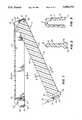
- FIG. 1is a vertical sectional view of a closure member constructed in accordance with this invention.
- FIG. 2is a sectional view of the blade of the closure member of FIG. 1, taken along the line II--II of FIG. 1.
- FIG. 3is a sectional view of the sheath of the closure member of FIG. 1, taken along the line III--III of FIG. 1.
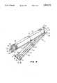
- FIG. 4is a perspective view of the closure member of FIG. 1.
- FIG. 5is a schematic view illustrating an ice bag for use with the closure member of FIG. 1.
- FIG. 6is an enlarged, partial, sectional view of the closure member of FIG. 1, showing the blade in a closed position.
- FIG. 7is an enlarged, partial, sectional view of the closure member of FIG. 1, showing the locking member being pulled back in order to release the blade from the closed position.
- closure member 11includes a longitudinal sheath 13.
- Sheath 13has parallel, longitudinal side walls 15.
- a base 17joins the inner edges 18 of the side walls 15.
- Base 17is perpendicular to the side walls 15.
- the outer edges 19 of the side walls 15are open and spaced apart from each other to define a slot.
- a lip 21extends along the exterior of each side wall 15 at the outer edge 19.
- Sheath 13has a pivot end 23 and a locking end 25.
- a pin 27, shown in FIG. 1extends between the side walls 15 at the pivot end 23.
- a stiffening section 29is integrally formed with each side wall 15 and locates at the exterior of each side wall 15 at the pivot end 23.
- the base 17has a pivot end 31 that is spaced a short distance inward from the locked pivot end 23 of the side walls 15.
- the pivot end 23 of each side wall 15is not perpendicular to the parallel inner and outer edges 18, 19, rather it is inclined at an angle of about 110 degrees relative to the inner edge 18.
- Sheath 13includes a partition 33 which is located near the locking end 25. Partition 33 extends from the inner edge 18 to the outer edge 19. Partition 33 is an integrally formed web between the side walls 15. Partition 33 has a locking shoulder 35 that faces toward the inner edge 18. Partition 33 is uniform in thickness, resulting in a shoulder 37 on the pivot end side of the partition 33. Shoulder 37 faces toward the outer edge 19. Shoulder 35 is parallel to the inner and outer edges 18, 19 and located about midway between the inner and outer edges 18, 19.
- the base 17has a locking end 39 that is spaced from the partition 33. This results in a clearance between the base locking end 39 and the partition 33. In this clearance, the side walls 15 of sheath 13 are not joined to each other.
- a retaining wall 41locates at the locking end 25 of sheath 13
- Retaining wall 41is parallel to the partition 33, and thus perpendicular to the side walls 15.
- Retaining wall 41extends from the outer edges 19 of side walls 15 and joins the side walls 15 for a selected distance toward the inner edges 18.
- the retaining wall 41extends for a length that is less than the distance from the inner edge 18 to the locking shoulder 35. The distance is approximately the same as the distance from the outer edge 19 to the shoulder 37.
- the partition 33 and retaining wall 41define a slot 42 between them.
- the inner edges 18 of the side walls 15have a recessed section 43.
- Recessed section 43begins at the retaining wall 41 and extends at an angle of about 130 degrees relative to the retaining wall 41.
- the inclined recessed section 43joins the portion of the inner edge 18 at a point between the retaining wall 41 and partition 33.
- a stiffening section 45locates at the locking end 25.
- the stiffening section 45comprises a thicker section of side walls 15, and joins lip 21.
- Closure member 11includes a blade 47 that will snap into sheath 13.
- Blade 47has a pivot end 49 and a locking end 51.
- Blade 47has an inner edge 53 that will locate between the side walls 15 adjacent base 17.
- Blade 47has an outer edge 55 that will locate outward of the sheath side wall outer edges 19.
- a plurality of longitudinal ribs 57extend along the length of blade 47. Ribs 57 locate on each side of blade 47 and protrude outward. Ribs 57 are parallel to each other and frictionally engage the interior surfaces of the side walls 15.
- the inner edge 53includes one of the ribs 57, as shown in FIG. 2.
- a base 59 of blade 47extends along the outer edge 55. Base 59 is rectangular in cross section and thicker than the remaining thickness of the blade 47. Base 59 locates on the outside of sheath 13 when the blade 47 is in the closed position.
- Blade 47has a hook 61 on its pivot end 49.
- Hook 61locates at the outer edge 55.
- Hook 61defines a circular slot 62 for snapping over the pin 27.
- hook 61 and pin 27serve as means for allowing the blade 47 to rotate or pivot between the open position shown in FIG. 1 and a closed position, shown partially in FIG. 6.
- Base 47has a greater transverse width than the distance between the outer edges 19 of the sheath 13. Portions of base 47 will contact the outer edges 19 of sheath 13 when the blade 47 is in the closed position.
- Blade 47has a pair of small protuberances 63, 65 on its inner edge 53. Each protuberance 63, 65 extends inward beyond the inner edge 53 a short distance. Protuberance 63 locates next to the pivot end 31 of base 17 when blade 47 is in the closed position. Protuberance 65 locates in the clearance between the base locking end 39 and the partition 33 when blade 47 is in the closed position.
- a locking member 67extends from the locking end 51 of blade 47.
- Locking member 67is resilient. It has a U-shaped section 69 that joins the outer edge 55 and the locking end 51 of the blade 47.
- the locking member 67extends inward, perpendicular to the blade outer edge 55.
- a tip 71locates on the end of the locking member 67. Tip 71 protrudes past the inner edge 53 of blade 47.
- a clearance 72will be between the locking end 51 and locking member 67.
- a locking shoulder 73locates in the clearance 72 on the side of locking member 67 that faces the locking end 51 of blade 47. Shoulder 73 is parallel to outer edge 55 and faces in the direction of outer edge 55. As shown in FIG. 6, locking member shoulder 73 is positioned to frictionally engage the partition locking shoulder 35 when the blade 47 is in the locked position shown in FIG. 6. Cam surface 74 inclines between the shoulder 73 and the tip 71. The locking member 67 is thicker at the shoulder 73 than at the tip 71.
- the closure member 11(FIG. 4) will be utilized with an ice bag 75.
- Ice bag 75is a plastic flexible bag for receiving ice 77.
- a flap 79 on one endserves as a hand hold.
- a loading chute 81locates on the other end.
- the ice bag 75fits within a cloth bag 83 for insulation. Securing strips 85 will secure the cloth bag 83 when the ice bag 75 is sealed with a closure member 11 (FIG. 4).
- the closure member 11may be opened by pressing cam surface 74 in a direction toward the retaining wall 41.
- pressing downward on tip 71will cause the blade 47 to move to the open position shown in FIG. 4.
- the slot 42 between the retaining wall 41 and the partition 33will accommodate the locking member 67 as it moves between the open and closed positions.
- the sides of the bag 75will be placed in contact with each other below the flap 79.
- the closure memberwill be inserted over this portion of bag 75.
- the protuberances 63, 65serve as guides for placement of the bag 75.
- the userwill then press the blade 47 toward the sheath 13.
- the locking member 67will slide through slot 42.
- the cam surface 74will slide on the partition 33.
- the resilient bias of the locking member 67pulls the locking member 67 toward the blade 47. Once the locking member shoulder 73 reaches the partition shoulder 35, it will slide over to the position shown in FIG. 6.
- the ribs 57will press the sides of the bag 75 tightly against the interior surfaces of the sheath side walls 15. Each rib 57 forms an independent seal.
- the flap 79 and loading chute 81will be folded over and inserted with the closure member 11 into the bag 83.
- the bag 83will be closed with the strips 85.
- the inventionhas significant advantages.
- the locking memberreadily opens utilizing only one hand.
- the retaining wallserves to protect the locking member from inadvertent opening.
- the separate pieces of the blade and sheathallow more efficient molding.
- the ribsform multiple independent seals.
Landscapes
- Engineering & Computer Science (AREA)
- Mechanical Engineering (AREA)
- Bag Frames (AREA)
Abstract
Description
Claims (10)
Priority Applications (1)
| Application Number | Priority Date | Filing Date | Title |
|---|---|---|---|
| US07/598,357US5050272A (en) | 1990-10-16 | 1990-10-16 | Closure member for an ice bag |
Applications Claiming Priority (1)
| Application Number | Priority Date | Filing Date | Title |
|---|---|---|---|
| US07/598,357US5050272A (en) | 1990-10-16 | 1990-10-16 | Closure member for an ice bag |
Publications (1)
| Publication Number | Publication Date |
|---|---|
| US5050272Atrue US5050272A (en) | 1991-09-24 |
Family
ID=24395239
Family Applications (1)
| Application Number | Title | Priority Date | Filing Date |
|---|---|---|---|
| US07/598,357Expired - LifetimeUS5050272A (en) | 1990-10-16 | 1990-10-16 | Closure member for an ice bag |
Country Status (1)
| Country | Link |
|---|---|
| US (1) | US5050272A (en) |
Cited By (67)
| Publication number | Priority date | Publication date | Assignee | Title |
|---|---|---|---|---|
| US5115542A (en)* | 1991-10-17 | 1992-05-26 | Navistar International Transportation Corp. | Hose separator clip |
| US5125133A (en)* | 1991-11-25 | 1992-06-30 | Hollister Incorporated | Ostomy pouch clamp with hinge-supplementing guide blade |
| GB2266701A (en)* | 1992-05-08 | 1993-11-10 | John David Johnson | Improvements in sealing of camera housings |
| USD350696S (en) | 1992-02-20 | 1994-09-20 | Weland Medical Ab | Bag clip |
| US5375300A (en)* | 1993-10-13 | 1994-12-27 | Chen; David | Clip device for sealing a bag |
| US5379489A (en)* | 1993-04-13 | 1995-01-10 | Struckmeyer Corporation | Bag closure clamp with hinge-supplementing complementary cam surfaces |
| US5423831A (en)* | 1991-01-24 | 1995-06-13 | Nates; Colin | Clamp |
| US5428871A (en)* | 1993-10-21 | 1995-07-04 | C. R. Bard, Inc. | Clamp for elastomeric bags |
| US5576704A (en)* | 1994-12-01 | 1996-11-19 | Caterpillar Inc. | Capacitive joystick apparatus |
| US5604959A (en)* | 1995-09-28 | 1997-02-25 | Tecnol Medical Products, Inc. | Ice pack clip |
| US5619775A (en)* | 1994-07-29 | 1997-04-15 | Klinck; Barry W. | Safety latch for a removable clip for a colostomy bag |
| US5641325A (en)* | 1993-04-13 | 1997-06-24 | Tecnol, Inc. | Ice pack |
| US5653003A (en)* | 1996-04-04 | 1997-08-05 | Freeman; William David | Shoulder harness recoil restraint clip |
| US5713108A (en)* | 1996-06-27 | 1998-02-03 | Solomon; Howard | Flexible bag sealing device |
| US5723002A (en) | 1993-04-13 | 1998-03-03 | Tecnol, Inc. | Ice pack |
| WO1999019223A1 (en)* | 1997-10-09 | 1999-04-22 | Folkmar, Raphaela | Hinged clip |
| USD413804S (en)* | 1998-01-13 | 1999-09-14 | Playtex Products, Inc. | Closure clip |
| US5968023A (en)* | 1994-12-22 | 1999-10-19 | Coloplast A/S | Collecting bag for human body wastes, particularly a stoma bag, and a closure clip for closing a bag |
| USD431004S (en)* | 1999-11-29 | 2000-09-19 | Weland Medical Ab | Bag clip |
| US6163940A (en)* | 1998-12-09 | 2000-12-26 | Vanmaanen; Kevin | Shoe fringe clamp |
| WO2000043281A3 (en)* | 1999-01-07 | 2001-04-05 | Aviat Tectonics Inc | Fastening, bundling and closure device and dispensing arrangements therefor |
| US6231234B1 (en) | 1998-05-13 | 2001-05-15 | Tc Manufacturing Co., Inc. | One piece snap closure for a plastic bag |
| WO2002076836A2 (en) | 2001-03-22 | 2002-10-03 | Folkmar, Raphaela | Clip with separable jaws |
| US20030109838A1 (en)* | 2000-07-18 | 2003-06-12 | Morton Jesse R. | Ostomy appliance with integral closure |
| US20030198704A1 (en)* | 2002-04-23 | 2003-10-23 | Blum John L. | Ostomy pouch clamp |
| US20040052435A1 (en)* | 2002-09-13 | 2004-03-18 | Kimberly-Clark Worldwide, Inc. | Article of manufacture resulting from automated assembly of a multi-part closure device with a product |
| US20040050019A1 (en)* | 2002-09-13 | 2004-03-18 | Kimberly-Clark Worldwide, Inc. | Process for automating the attachment of a clip to a product |
| WO2004024580A1 (en)* | 2002-09-13 | 2004-03-25 | Kimberly-Clark Worldwide, Inc. | Multi-part closure device |
| US20040104316A1 (en)* | 2002-11-27 | 2004-06-03 | Turvey Robert R. | Method and device for suspending pouches |
| US20040187274A1 (en)* | 2002-11-27 | 2004-09-30 | Turvey Robert R. | Holding device |
| US20050280181A1 (en)* | 2004-06-18 | 2005-12-22 | Turvey Robert R | Apparatus for and method of forming indentations in a closure strip |
| US20050281492A1 (en)* | 2004-06-18 | 2005-12-22 | Turvey Robert R | Pouch and closure for a pouch |
| US20050278906A1 (en)* | 2004-06-18 | 2005-12-22 | Charles Moncavage | Seat belt lock for child safety seat |
| USD519368S1 (en) | 2005-01-31 | 2006-04-25 | S.C. Johnson Home Storage, Inc. | Swivel slider body with handle |
| US20060107502A1 (en)* | 2002-10-23 | 2006-05-25 | Jms Co., Ltd | Clip for dividing two liquids |
| USD527683S1 (en) | 2005-01-31 | 2006-09-05 | S.C. Johnson Home Storage, Inc. | Combined swivel slider body with loop for reclosable bags |
| US20090107525A1 (en)* | 2007-10-25 | 2009-04-30 | David Chiappetta | String cleaning system |
| USD625173S1 (en)* | 2009-08-18 | 2010-10-12 | Conopco Inc. | Sachet closing device |
| USD625174S1 (en)* | 2009-08-18 | 2010-10-12 | Conopco Inc. | Sachet closing device |
| US20120102890A1 (en)* | 2008-12-18 | 2012-05-03 | Fily Sebastien Lucien | Closure for pouches |
| US8746742B2 (en) | 2012-07-30 | 2014-06-10 | Leroy Heath | Seatbelt tension adjustment device |
| US9004536B2 (en) | 2012-07-30 | 2015-04-14 | Leroy Heath | Seatbelt tension adjustment device |
| US10247212B2 (en)* | 2017-07-27 | 2019-04-02 | Lawrence E. Nunes | Device for mounting an object |
| US10717571B1 (en) | 2018-03-06 | 2020-07-21 | Gatekeeper Innovation, Inc. | Clam shell cover cap and method of use |
| USD898343S1 (en)* | 2018-06-17 | 2020-10-13 | Hydrapak Llc | Reservoir lip |
| USD907204S1 (en) | 2019-08-02 | 2021-01-05 | Covidien Lp | Ligation clip |
| USD907200S1 (en) | 2019-08-05 | 2021-01-05 | Covidien Lp | Ligation clip |
| USD907203S1 (en) | 2019-08-02 | 2021-01-05 | Covidien Lp | Ligation clip |
| US10932788B2 (en) | 2018-04-11 | 2021-03-02 | Covidien Lp | Ligation clip with latching and retention features |
| US10932789B2 (en) | 2018-04-11 | 2021-03-02 | Covidien Lp | Ligation clip with latching and retention features |
| US11008777B2 (en) | 2014-03-26 | 2021-05-18 | Gatekeeper Innovation, Inc. | Locking cap with push button reset |
| US11033279B2 (en) | 2018-04-24 | 2021-06-15 | Covidien Lp | Ligation clip with retention features |
| US11273963B2 (en) | 2009-09-03 | 2022-03-15 | Gatekeeper Innovation, Inc. | Lockable cap for medical prescription bottle |
| US11279535B1 (en) | 2018-03-06 | 2022-03-22 | Gatekeeper Innovation, Inc. | Clam shell cover cap and method of use |
| US11286081B2 (en) | 2020-06-04 | 2022-03-29 | Safeseal-Systems | Self-sealing container |
| US11304703B2 (en) | 2018-05-25 | 2022-04-19 | Covidien Lp | Ligation clip removal device |
| US11304704B2 (en) | 2018-08-22 | 2022-04-19 | Covidien Lp | Surgical clip applier and ligation clips |
| US11312542B1 (en)* | 2021-11-11 | 2022-04-26 | Wei K. Hsu | Closure device for flexible bag |
| US11317923B2 (en) | 2018-08-13 | 2022-05-03 | Covidien Lp | Ligation clip with improved hinge |
| US11395660B2 (en) | 2019-08-05 | 2022-07-26 | Covidien Lp | Stackable ligation clip |
| US11471165B2 (en) | 2019-05-08 | 2022-10-18 | Covidien Lp | Ligation clip cartridge |
| US11472605B2 (en) | 2020-06-04 | 2022-10-18 | Safeseal-Systems | Securable clip |
| US11696764B2 (en) | 2020-01-31 | 2023-07-11 | Covidien Lp | Ligation clip with controlled tissue compression |
| US11707282B2 (en) | 2019-07-02 | 2023-07-25 | Covidien Lp | Multi-piece ligation clip |
| USD993411S1 (en) | 2017-11-03 | 2023-07-25 | Covidien Lp | Ligation clip with controlled tissue compression |
| US12114866B2 (en) | 2020-03-26 | 2024-10-15 | Covidien Lp | Interoperative clip loading device |
| US12234070B2 (en) | 2009-09-03 | 2025-02-25 | Rxguardian Inc. | Container device and method for securing same |
Citations (6)
| Publication number | Priority date | Publication date | Assignee | Title |
|---|---|---|---|---|
| US3523534A (en)* | 1967-04-05 | 1970-08-11 | Hollister Inc | Closure for drainage pouch |
| US4038726A (en)* | 1975-07-01 | 1977-08-02 | Kohshoh Limited | Plastic adjuster for a belt |
| US4275485A (en)* | 1979-12-10 | 1981-06-30 | Hutchison Charles L | Sealing devices |
| US4523353A (en)* | 1980-09-05 | 1985-06-18 | Tecnol, Inc. | Small ice packs and method of manufacturing the same |
| US4551888A (en)* | 1983-09-23 | 1985-11-12 | Illinois Tool Works Inc. | Bag shut-off clamp |
| US4887335A (en)* | 1987-11-16 | 1989-12-19 | Ice-Pack Service Ag | Closure for closing plastic bags and the like |
- 1990
- 1990-10-16USUS07/598,357patent/US5050272A/ennot_activeExpired - Lifetime
Patent Citations (6)
| Publication number | Priority date | Publication date | Assignee | Title |
|---|---|---|---|---|
| US3523534A (en)* | 1967-04-05 | 1970-08-11 | Hollister Inc | Closure for drainage pouch |
| US4038726A (en)* | 1975-07-01 | 1977-08-02 | Kohshoh Limited | Plastic adjuster for a belt |
| US4275485A (en)* | 1979-12-10 | 1981-06-30 | Hutchison Charles L | Sealing devices |
| US4523353A (en)* | 1980-09-05 | 1985-06-18 | Tecnol, Inc. | Small ice packs and method of manufacturing the same |
| US4551888A (en)* | 1983-09-23 | 1985-11-12 | Illinois Tool Works Inc. | Bag shut-off clamp |
| US4887335A (en)* | 1987-11-16 | 1989-12-19 | Ice-Pack Service Ag | Closure for closing plastic bags and the like |
Cited By (89)
| Publication number | Priority date | Publication date | Assignee | Title |
|---|---|---|---|---|
| US5423831A (en)* | 1991-01-24 | 1995-06-13 | Nates; Colin | Clamp |
| US5115542A (en)* | 1991-10-17 | 1992-05-26 | Navistar International Transportation Corp. | Hose separator clip |
| US5125133A (en)* | 1991-11-25 | 1992-06-30 | Hollister Incorporated | Ostomy pouch clamp with hinge-supplementing guide blade |
| USD350696S (en) | 1992-02-20 | 1994-09-20 | Weland Medical Ab | Bag clip |
| GB2266701A (en)* | 1992-05-08 | 1993-11-10 | John David Johnson | Improvements in sealing of camera housings |
| US5641325A (en)* | 1993-04-13 | 1997-06-24 | Tecnol, Inc. | Ice pack |
| US5379489A (en)* | 1993-04-13 | 1995-01-10 | Struckmeyer Corporation | Bag closure clamp with hinge-supplementing complementary cam surfaces |
| US5723002A (en) | 1993-04-13 | 1998-03-03 | Tecnol, Inc. | Ice pack |
| US5375300A (en)* | 1993-10-13 | 1994-12-27 | Chen; David | Clip device for sealing a bag |
| US5428871A (en)* | 1993-10-21 | 1995-07-04 | C. R. Bard, Inc. | Clamp for elastomeric bags |
| US5619775A (en)* | 1994-07-29 | 1997-04-15 | Klinck; Barry W. | Safety latch for a removable clip for a colostomy bag |
| US5576704A (en)* | 1994-12-01 | 1996-11-19 | Caterpillar Inc. | Capacitive joystick apparatus |
| US5968023A (en)* | 1994-12-22 | 1999-10-19 | Coloplast A/S | Collecting bag for human body wastes, particularly a stoma bag, and a closure clip for closing a bag |
| US5604959A (en)* | 1995-09-28 | 1997-02-25 | Tecnol Medical Products, Inc. | Ice pack clip |
| US5653003A (en)* | 1996-04-04 | 1997-08-05 | Freeman; William David | Shoulder harness recoil restraint clip |
| US5713108A (en)* | 1996-06-27 | 1998-02-03 | Solomon; Howard | Flexible bag sealing device |
| WO1999019223A1 (en)* | 1997-10-09 | 1999-04-22 | Folkmar, Raphaela | Hinged clip |
| USD413804S (en)* | 1998-01-13 | 1999-09-14 | Playtex Products, Inc. | Closure clip |
| US6231234B1 (en) | 1998-05-13 | 2001-05-15 | Tc Manufacturing Co., Inc. | One piece snap closure for a plastic bag |
| US6163940A (en)* | 1998-12-09 | 2000-12-26 | Vanmaanen; Kevin | Shoe fringe clamp |
| WO2000043281A3 (en)* | 1999-01-07 | 2001-04-05 | Aviat Tectonics Inc | Fastening, bundling and closure device and dispensing arrangements therefor |
| USD431004S (en)* | 1999-11-29 | 2000-09-19 | Weland Medical Ab | Bag clip |
| US6764473B2 (en)* | 2000-07-18 | 2004-07-20 | Morton Jesse R | Ostomy appliance with integral closure |
| US20030109838A1 (en)* | 2000-07-18 | 2003-06-12 | Morton Jesse R. | Ostomy appliance with integral closure |
| WO2002076836A3 (en)* | 2001-03-22 | 2003-01-16 | Jan Folkmar | Clip with separable jaws |
| US7131169B2 (en)* | 2001-03-22 | 2006-11-07 | Jan Folkmar | Hinged clip with separable jaws |
| WO2002076836A2 (en) | 2001-03-22 | 2002-10-03 | Folkmar, Raphaela | Clip with separable jaws |
| US20030198704A1 (en)* | 2002-04-23 | 2003-10-23 | Blum John L. | Ostomy pouch clamp |
| US6702794B2 (en)* | 2002-04-23 | 2004-03-09 | Bristol-Myers Squibb Company | Ostomy pouch clamp |
| US20040050019A1 (en)* | 2002-09-13 | 2004-03-18 | Kimberly-Clark Worldwide, Inc. | Process for automating the attachment of a clip to a product |
| WO2004024581A1 (en)* | 2002-09-13 | 2004-03-25 | Kimberly-Clark Worldwide, Inc. | Pouch provided with a multi-part clip arrangement in an automated assembly process |
| US6959523B2 (en) | 2002-09-13 | 2005-11-01 | Kimberly-Clark Worldwide, Inc. | Process for automating the attachment of a clip to a product |
| WO2004024580A1 (en)* | 2002-09-13 | 2004-03-25 | Kimberly-Clark Worldwide, Inc. | Multi-part closure device |
| US20040052435A1 (en)* | 2002-09-13 | 2004-03-18 | Kimberly-Clark Worldwide, Inc. | Article of manufacture resulting from automated assembly of a multi-part closure device with a product |
| US6886982B2 (en) | 2002-09-13 | 2005-05-03 | Kimberly-Clark Worldwide, Inc. | Article of manufacture resulting from automated assembly of a multi-part closure device with a product |
| US6904646B2 (en) | 2002-09-13 | 2005-06-14 | Kimberly-Clark Worldwide, Inc. | Multi-part closure device |
| US7428771B2 (en)* | 2002-10-23 | 2008-09-30 | Jms Co., Ltd. | Clip for dividing two liquids |
| US20060107502A1 (en)* | 2002-10-23 | 2006-05-25 | Jms Co., Ltd | Clip for dividing two liquids |
| US20040187274A1 (en)* | 2002-11-27 | 2004-09-30 | Turvey Robert R. | Holding device |
| US20040104316A1 (en)* | 2002-11-27 | 2004-06-03 | Turvey Robert R. | Method and device for suspending pouches |
| US20050281492A1 (en)* | 2004-06-18 | 2005-12-22 | Turvey Robert R | Pouch and closure for a pouch |
| US20050278906A1 (en)* | 2004-06-18 | 2005-12-22 | Charles Moncavage | Seat belt lock for child safety seat |
| US20050280181A1 (en)* | 2004-06-18 | 2005-12-22 | Turvey Robert R | Apparatus for and method of forming indentations in a closure strip |
| USD519368S1 (en) | 2005-01-31 | 2006-04-25 | S.C. Johnson Home Storage, Inc. | Swivel slider body with handle |
| USD527683S1 (en) | 2005-01-31 | 2006-09-05 | S.C. Johnson Home Storage, Inc. | Combined swivel slider body with loop for reclosable bags |
| US8132286B2 (en)* | 2007-10-25 | 2012-03-13 | David Chiappetta | String cleaning system |
| US20090107525A1 (en)* | 2007-10-25 | 2009-04-30 | David Chiappetta | String cleaning system |
| US9078502B2 (en)* | 2008-12-18 | 2015-07-14 | Bayer Consumer Care Ag | Closure for pouches |
| US20120102890A1 (en)* | 2008-12-18 | 2012-05-03 | Fily Sebastien Lucien | Closure for pouches |
| USD625174S1 (en)* | 2009-08-18 | 2010-10-12 | Conopco Inc. | Sachet closing device |
| USD625173S1 (en)* | 2009-08-18 | 2010-10-12 | Conopco Inc. | Sachet closing device |
| US12234070B2 (en) | 2009-09-03 | 2025-02-25 | Rxguardian Inc. | Container device and method for securing same |
| US11273963B2 (en) | 2009-09-03 | 2022-03-15 | Gatekeeper Innovation, Inc. | Lockable cap for medical prescription bottle |
| US8746742B2 (en) | 2012-07-30 | 2014-06-10 | Leroy Heath | Seatbelt tension adjustment device |
| US9004536B2 (en) | 2012-07-30 | 2015-04-14 | Leroy Heath | Seatbelt tension adjustment device |
| US11008777B2 (en) | 2014-03-26 | 2021-05-18 | Gatekeeper Innovation, Inc. | Locking cap with push button reset |
| US10247212B2 (en)* | 2017-07-27 | 2019-04-02 | Lawrence E. Nunes | Device for mounting an object |
| USD993411S1 (en) | 2017-11-03 | 2023-07-25 | Covidien Lp | Ligation clip with controlled tissue compression |
| US11267625B2 (en) | 2018-03-06 | 2022-03-08 | Gatekeeper Innovation, Inc. | Clam shell cover cap and method of use |
| US11279535B1 (en) | 2018-03-06 | 2022-03-22 | Gatekeeper Innovation, Inc. | Clam shell cover cap and method of use |
| US11845596B2 (en) | 2018-03-06 | 2023-12-19 | Rxguardian Inc. | Clam shell cover cap and method of use |
| US10717571B1 (en) | 2018-03-06 | 2020-07-21 | Gatekeeper Innovation, Inc. | Clam shell cover cap and method of use |
| US11845597B2 (en) | 2018-03-06 | 2023-12-19 | Rxguardian Inc. | Clam shell cover cap and method of use |
| US10932789B2 (en) | 2018-04-11 | 2021-03-02 | Covidien Lp | Ligation clip with latching and retention features |
| US10932788B2 (en) | 2018-04-11 | 2021-03-02 | Covidien Lp | Ligation clip with latching and retention features |
| US11033279B2 (en) | 2018-04-24 | 2021-06-15 | Covidien Lp | Ligation clip with retention features |
| US11304703B2 (en) | 2018-05-25 | 2022-04-19 | Covidien Lp | Ligation clip removal device |
| USD898343S1 (en)* | 2018-06-17 | 2020-10-13 | Hydrapak Llc | Reservoir lip |
| US11317923B2 (en) | 2018-08-13 | 2022-05-03 | Covidien Lp | Ligation clip with improved hinge |
| US11304704B2 (en) | 2018-08-22 | 2022-04-19 | Covidien Lp | Surgical clip applier and ligation clips |
| US11471165B2 (en) | 2019-05-08 | 2022-10-18 | Covidien Lp | Ligation clip cartridge |
| US12285176B2 (en) | 2019-07-02 | 2025-04-29 | Covidien Lp | Multi-piece ligation clip |
| US11707282B2 (en) | 2019-07-02 | 2023-07-25 | Covidien Lp | Multi-piece ligation clip |
| USD907204S1 (en) | 2019-08-02 | 2021-01-05 | Covidien Lp | Ligation clip |
| USD907203S1 (en) | 2019-08-02 | 2021-01-05 | Covidien Lp | Ligation clip |
| US11395660B2 (en) | 2019-08-05 | 2022-07-26 | Covidien Lp | Stackable ligation clip |
| USD907200S1 (en) | 2019-08-05 | 2021-01-05 | Covidien Lp | Ligation clip |
| US11696764B2 (en) | 2020-01-31 | 2023-07-11 | Covidien Lp | Ligation clip with controlled tissue compression |
| US12114866B2 (en) | 2020-03-26 | 2024-10-15 | Covidien Lp | Interoperative clip loading device |
| US11472605B2 (en) | 2020-06-04 | 2022-10-18 | Safeseal-Systems | Securable clip |
| US11667430B2 (en) | 2020-06-04 | 2023-06-06 | Safeseal-Systems | Self-sealing container |
| US11667440B2 (en) | 2020-06-04 | 2023-06-06 | Safeseal-Systems | Securable clip |
| US11661243B2 (en) | 2020-06-04 | 2023-05-30 | Safeseal-Systems | Securable clip |
| US11661242B2 (en) | 2020-06-04 | 2023-05-30 | Safeseal-Systems | Securable clip |
| US11655067B2 (en) | 2020-06-04 | 2023-05-23 | Safeseal-Systems | Self-sealing container |
| US11542059B2 (en) | 2020-06-04 | 2023-01-03 | Safeseal-Systems | Self-sealing container |
| US11542058B2 (en) | 2020-06-04 | 2023-01-03 | Safeseal-Systems | Self-sealing container |
| US11286081B2 (en) | 2020-06-04 | 2022-03-29 | Safeseal-Systems | Self-sealing container |
| US11312542B1 (en)* | 2021-11-11 | 2022-04-26 | Wei K. Hsu | Closure device for flexible bag |
Similar Documents
| Publication | Publication Date | Title |
|---|---|---|
| US5050272A (en) | Closure member for an ice bag | |
| CA1319810C (en) | Closure means for closing plastic bags and the like | |
| US6036364A (en) | Two-piece sliding fastener arrangement for attachment to container | |
| JP3026839B2 (en) | Leak-proof fastener with slider | |
| EP1761438B1 (en) | Leak proof closure device with spring member | |
| EP2040989B1 (en) | Fastener strip, slider and reclosable container comprising same | |
| US6948849B2 (en) | Resealable closure mechanism having a slider device and methods | |
| JP4044153B2 (en) | Resealable fastener assembly | |
| US4787552A (en) | Case for packaging | |
| JP2001072087A (en) | Resealable zipper assembly, resealable package, carrier web, and method to form resealable package | |
| US6058572A (en) | Clip | |
| IE48271B1 (en) | Closure device | |
| KR100285879B1 (en) | A zipper bag and a slider for opening/ closing the bag | |
| US20030235351A1 (en) | Assembly having slider mounted inside zipper for reclosable packaging | |
| FI83949B (en) | A sealer for sealing bags, thin-walled tubes or the like in a liquid-tight manner | |
| JP3657560B2 (en) | Especially for sewing needle packages | |
| EP1017593B1 (en) | Resealable pouch for tobacco | |
| KR200417212Y1 (en) | Cake packaging box | |
| US20050196077A1 (en) | Slider for sealable storage bag and sealable storage bag provided with the slider | |
| US20050141787A1 (en) | Snap on envelope | |
| KR102535045B1 (en) | Item of kitchenware | |
| US4200132A (en) | Moisture proof bag closure | |
| JPS61259959A (en) | Bag body with claw tool | |
| JP3663260B2 (en) | Sealed container | |
| JP3668571B2 (en) | Sealed container |
Legal Events
| Date | Code | Title | Description |
|---|---|---|---|
| AS | Assignment | Owner name:ANAGO, INC., A CORP. OF TX, TEXAS Free format text:ASSIGNMENT OF ASSIGNORS INTEREST.;ASSIGNOR:ROBINSON, STEVEN R.;REEL/FRAME:005484/0701 Effective date:19901008 Owner name:ANAGO, INC., A CORP. OF TX, TEXAS Free format text:ASSIGNMENT OF ASSIGNORS INTEREST.;ASSIGNOR:HAMPTON, CLIFTON G.;REEL/FRAME:005484/0698 Effective date:19901008 | |
| STCF | Information on status: patent grant | Free format text:PATENTED CASE | |
| FEPP | Fee payment procedure | Free format text:PAYOR NUMBER ASSIGNED (ORIGINAL EVENT CODE: ASPN); ENTITY STATUS OF PATENT OWNER: LARGE ENTITY | |
| AS | Assignment | Owner name:TCNL TECHNOLOGIES, INC., DELAWARE Free format text:ASSIGNMENT OF ASSIGNORS INTEREST;ASSIGNOR:ANAGO INCORPORATED;REEL/FRAME:006936/0471 Effective date:19940316 | |
| FEPP | Fee payment procedure | Free format text:PAT HLDR NO LONGER CLAIMS SMALL ENT STAT AS SMALL BUSINESS (ORIGINAL EVENT CODE: LSM2); ENTITY STATUS OF PATENT OWNER: LARGE ENTITY Free format text:PAYOR NUMBER ASSIGNED (ORIGINAL EVENT CODE: ASPN); ENTITY STATUS OF PATENT OWNER: LARGE ENTITY Free format text:PAYER NUMBER DE-ASSIGNED (ORIGINAL EVENT CODE: RMPN); ENTITY STATUS OF PATENT OWNER: LARGE ENTITY | |
| FPAY | Fee payment | Year of fee payment:4 | |
| FPAY | Fee payment | Year of fee payment:8 | |
| AS | Assignment | Owner name:KIMBERLY-CLARK WORLDWIDE, INC., GEORGIA Free format text:ASSIGNMENT OF ASSIGNORS INTEREST;ASSIGNOR:TECNOL MEDICAL PRODUCTS, INC.;REEL/FRAME:010589/0471 Effective date:20000117 | |
| FPAY | Fee payment | Year of fee payment:12 |