US5049146A - Blood/gas separator and flow system - Google Patents
Blood/gas separator and flow systemDownload PDFInfo
- Publication number
- US5049146A US5049146AUS07/359,178US35917889AUS5049146AUS 5049146 AUS5049146 AUS 5049146AUS 35917889 AUS35917889 AUS 35917889AUS 5049146 AUS5049146 AUS 5049146A
- Authority
- US
- United States
- Prior art keywords
- blood
- flexible bag
- cardiotomy
- lower compartment
- inlet
- Prior art date
- Legal status (The legal status is an assumption and is not a legal conclusion. Google has not performed a legal analysis and makes no representation as to the accuracy of the status listed.)
- Expired - Fee Related
Links
Images


Classifications
- A—HUMAN NECESSITIES
- A61—MEDICAL OR VETERINARY SCIENCE; HYGIENE
- A61M—DEVICES FOR INTRODUCING MEDIA INTO, OR ONTO, THE BODY; DEVICES FOR TRANSDUCING BODY MEDIA OR FOR TAKING MEDIA FROM THE BODY; DEVICES FOR PRODUCING OR ENDING SLEEP OR STUPOR
- A61M1/00—Suction or pumping devices for medical purposes; Devices for carrying-off, for treatment of, or for carrying-over, body-liquids; Drainage systems
- A61M1/36—Other treatment of blood in a by-pass of the natural circulatory system, e.g. temperature adaptation, irradiation ; Extra-corporeal blood circuits
- A61M1/3621—Extra-corporeal blood circuits
- A61M1/3627—Degassing devices; Buffer reservoirs; Drip chambers; Blood filters
- A—HUMAN NECESSITIES
- A61—MEDICAL OR VETERINARY SCIENCE; HYGIENE
- A61M—DEVICES FOR INTRODUCING MEDIA INTO, OR ONTO, THE BODY; DEVICES FOR TRANSDUCING BODY MEDIA OR FOR TAKING MEDIA FROM THE BODY; DEVICES FOR PRODUCING OR ENDING SLEEP OR STUPOR
- A61M1/00—Suction or pumping devices for medical purposes; Devices for carrying-off, for treatment of, or for carrying-over, body-liquids; Drainage systems
- A61M1/14—Dialysis systems; Artificial kidneys; Blood oxygenators ; Reciprocating systems for treatment of body fluids, e.g. single needle systems for hemofiltration or pheresis
- A61M1/32—Oxygenators without membranes
- A61M1/322—Antifoam; Defoaming
- A61M1/325—Surfactant coating; Improving wettability
- A—HUMAN NECESSITIES
- A61—MEDICAL OR VETERINARY SCIENCE; HYGIENE
- A61M—DEVICES FOR INTRODUCING MEDIA INTO, OR ONTO, THE BODY; DEVICES FOR TRANSDUCING BODY MEDIA OR FOR TAKING MEDIA FROM THE BODY; DEVICES FOR PRODUCING OR ENDING SLEEP OR STUPOR
- A61M1/00—Suction or pumping devices for medical purposes; Devices for carrying-off, for treatment of, or for carrying-over, body-liquids; Drainage systems
- A61M1/36—Other treatment of blood in a by-pass of the natural circulatory system, e.g. temperature adaptation, irradiation ; Extra-corporeal blood circuits
- A61M1/3621—Extra-corporeal blood circuits
- A61M1/3627—Degassing devices; Buffer reservoirs; Drip chambers; Blood filters
- A61M1/3632—Combined venous-cardiotomy reservoirs
- Y—GENERAL TAGGING OF NEW TECHNOLOGICAL DEVELOPMENTS; GENERAL TAGGING OF CROSS-SECTIONAL TECHNOLOGIES SPANNING OVER SEVERAL SECTIONS OF THE IPC; TECHNICAL SUBJECTS COVERED BY FORMER USPC CROSS-REFERENCE ART COLLECTIONS [XRACs] AND DIGESTS
- Y10—TECHNICAL SUBJECTS COVERED BY FORMER USPC
- Y10S—TECHNICAL SUBJECTS COVERED BY FORMER USPC CROSS-REFERENCE ART COLLECTIONS [XRACs] AND DIGESTS
- Y10S128/00—Surgery
- Y10S128/03—Heart-lung
Definitions
- the present inventionis concerned with blood reservoirs, and in particular venous and cardiotomy blood reservoirs.
- Extracorporeal circuitsgenerally include devices for performing various tasks on the blood, e.g. oxygenation, filtration, and storage. Other procedures requiring the routing of blood through an extracorporeal circuit include extracorporeal membrane oxygenation (long term support) and autotransfusion.
- Extracorporeal circuitsare typically set up by an individual known as a perfusionist.
- the perfusionistcontrols the rate of blood flow and operates the various devices connected in the circuit.
- Extracorporeal circuitsgenerally include oxygenators, heat exchangers, and filters, which are interconnected by surgical tubing. These circuits also include reservoirs.
- a blood reservoiris an enclosure into which blood is temporarily stored. The storage of blood in reservoirs allows regulation of the patient's blood volume and pressure.
- reservoirsalso include various elements to filter and defoam the blood.
- a first type of reservoiris one which is formed from a generally flexible bag or container. Blood will expand this type of reservoir as it enters the reservoir. The air to blood interface is limited by the lack of empty space in the reservoir prior to filling with blood. Generally such reservoirs are sealed from the external environment. Closed reservoirs have numerous advantages. Such reservoirs isolate the blood from air thus limiting the extent of the blood to air interface which is detrimental to blood components. Flexible containers collapse and expand as the quantity of blood varies without delivering large quantities of air downstream into the extracorporeal circuit. This reduces potential injury to the patient from air embolism, particularly when all of the blood is removed from the reservoir.
- closed reservoirsOne disadvantage with closed reservoirs is the inability to separate gross amounts of incoming air. The separation of small amounts of air from the blood is also difficult with closed reservoirs absent screen filters. It is also difficult to remove any entrapped air from the reservoir without physically compressing the bag, or by sucking or pumping the air out of the bag with a syringe or similar device.
- a second type of reservoiris known as an open reservoir, and is formed from a rigid or hardshell container.
- the reservoiris filled with air which is pushed out by the entering blood.
- airis removed during the priming process, but a small volume of the reservoir remains filled with air during the operation of the reservoir. This provides for an air to blood interface, which as stated may lead to the damage of various blood components.
- open reservoirsOne major advantage with open reservoirs is the establishment of the air to blood interface. Any air present in the incoming blood normally rises upwards through the blood passing across the blood to air interface. Such reservoirs typically include filters and defoaming elements which further enhance the release of entrapped gas across the blood to air interface. The released air is vented to atmosphere.
- open reservoirsallow for a precise measurement of the blood volume. That is, unlike the expanding and contracting closed reservoirs, open hardshell reservoirs allow for visual inspection of the quantity of blood flowing through the reservoir. By providing the hardshell reservoir with visually readable volume markings the precise amount of blood can be ascertained during the surgical procedure.
- Open reservoirsalso tend to impose a lower back pressure on the extracorporeal circuit. That is, blood flow through the reservoir will not increase the back pressure in the upstream portion of the circuit. Closed reservoirs induce a greater back pressure in the upstream portion of the circuit which may increase the amount of blood forced into the heart.
- Examples of flexible shell reservoirsare disclosed in many of the above patent references, while examples of hardshell reservoirs are found in some commercially available oxygenators, such as the BCM-7, a product manufactured and sold by the Baxter Healthcare Corporation, Deerfield, Ill., Capiox E. an oxygenator sold by Terumo Corporation, Tokyo, Japan; and the CML, an oxygenator sold by Cobe Corporation, Boulder, Colo.
- BCM-7a product manufactured and sold by the Baxter Healthcare Corporation, Deerfield, Ill.
- Capiox Ean oxygenator sold by Terumo Corporation, Tokyo, Japan
- CMLan oxygenator sold by Cobe Corporation, Boulder, Colo.
- Screenshave also been positioned in filtering bags. These bags are usually positioned at the upstream end of extracorporeal circuits, and filter out denatured blood components. Entrapped gas bubbles would be broken down passing through this filter bag assembly.
- An example of such a bagis disclosed in U.S. Pat. No. 4,035,304, issued to Watanabe on July 12, 1977.
- Foamis highly undesirable. While the foam may be merely removed from the circuit, it is the usual practice to separate any blood from the foam first. This is usually accomplished by passing the foam through a porous element which is at least partially coated with a defoaming substance, such as silicone antifoam.
- Reservoirshave been designed to include fiber or equivalent elements which are coated with this antifoam material. Silicone antifoam or a derivative compound, breaks foam down into blood and gas. The gas is usually vented to the environment.
- An example of such a reservoiris seen in U.S. Pat. No. 4,466,888, issued to Verkaart on Aug. 21, 1984.
- silicone antifoamor equivalent substance
- This materialcan become dislodged and shed into the blood.
- the shed antifoam materialcan become lodged in the patient's vascular system disrupting blood flow.
- Some researchershave suggested a mechanism for limiting the potential exposure of blood with silicone antifoam.
- a reservoirin combination with an oxygenator, is disclosed in U.S. patent application Ser. No. 338,347 filed Apr. 12, 1989, which is a continuation of U.S. Ser. No. 885,963, and assigned to the same assignee as the instant application.
- This applicationalso discloses a reservoir having a defoaming material generally positioned above the maximum blood level. As stated in this application, the positioning of the defoaming material above this maximum blood level reduces the potential contact between the blood and the material.
- the reservoir of the inventionincludes a hardshell housing which defines at least one blood compartment. This compartment remains substantially open to the atmosphere.
- a flexible bagis fixed in this compartment, and is connected to the blood inlet.
- the flexible bagis fixed in the compartment to allow for limited expansion.
- a first end of the bagis formed with a microporous screen and is situated in the hardshell to lie partially below a minimum blood level.
- a second bag endis formed to remain substantially open, and is positioned to lie above a maximum blood level in the hard shell.
- a porous body or matis positioned at least partially in the bag second end. This body or mat is partially coated with a defoaming substance.
- the blood entering the reservoirflows into and expands the flexible bag.
- the bloodflows downward through and out the microporous screen in the lower end.
- the placement of the lower end below the minimum blood levelensures that blood exiting the screen will not excessively mix with any air.
- Foam entering the bagrises upward and is brought into contact with the defoaming material coated porous body.
- the placement of this body above the maximum blood levelreduces the potential of contact between the blood and defoaming substance.
- the reservoir of the inventionthus possesses the advantages of a flexible shell, while retaining the advantages of a hardshell.
- the reservoirincludes two separate blood reservoir compartments.
- One compartmentis formed as described above and functions as a venous reservoir.
- a second compartmentfunctions as a cardiotomy reservoir.
- This reservoiris situated above the venous reservoir to allow for gravity flow from the cardiotomy to venous reservoirs.
- This latter compartmentincludes inlet and outlet ports, and a multilayered filter assembly through which passes the blood.
- This filter assemblyincludes a defoaming substance coated body or mat which is surrounded by a microporous filter. This assembly breaks down both small air bubbles and foam.
- Still other preferred embodimentsinclude an assembly for connecting the cardiotomy reservoir compartment to the venous reservoir compartment which reduces the passage of air from the former to the latter, and a design for the venous reservoir hardshell which is formed to provide easy reading and measurement of the quantity of blood in the venous reservoir compartment.
- FIG. 1is a prospective view of a reservoir mounted upon a stand in accordance with a preferred embodiment of the invention
- FIG. 2is a side view of the reservoir of FIG. 1 additionally illustrating an oxygenator releasably connected to the bottom of the reservoir;
- FIG. 3is a cross-sectional view of the reservoir of FIG. 1 along line 3--3;
- FIG. 4is a rear prospective view of a flexible bag assembly of the reservoir of the invention.
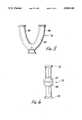
- FIG. 5is a side view of a Y-shaped connector in accordance with an embodiment of the invention.
- FIG. 6is a side view of a connector assembly in accordance with an embodiment of the invention.
- the present inventionis directed to open reservoirs, and specifically to open venous reservoirs.
- the venous reservoiris incorporated in a housing also having a cardiotomy reservoir.
- the reservoir of the inventionprovides the benefits of both hard and soft shell reservoirs by mounting a flexible bag in a hardshell.
- the bags flexibilityensures that the blood does not excessively mix with air.
- This aspect of the inventionis provided by designing the flexible bag so that the blood is directed downward through a lower microscreen portion that is positioned to discharge the blood partially below the minimum blood level in the reservoir.
- the flexible bagis further designed to include a defoamer coated membrane positioned above the maximum blood level in the reservoir.
- minimum blood levelit is meant the lowest level in the reservoir to which the blood will normally rise under normal blood flow and operating conditions for the particular reservoir.
- maximum blood levelit is meant the highest level in the reservoir to which the blood will normally rise under normal blood flow and operating conditions for the particular reservoir.
- the importance of providing for the downward flow of blood out through the screen below the minimum blood levelis to minimize the contact between flowing blood and air.
- the turbulence caused by the blood flowing out from the screenwould, if the screen is exposed to the air, cause a mixing action between the blood and air. This is an unwanted occurrence.
- the reservoir of the inventionis useful as a venous or cardiotomy blood reservoir, and may have any suitable shape or configuration.
- the inventionwill be described with reference to a venous reservoir upon which is positioned a cardiotomy reservoir.
- a venous and cardiotomy reservoir assemblyis seen generally at 10.
- the venous and cardiotomy reservoir assembly 10is seen mounted upon a stand 12.
- Stand 12includes a base portion 14 up from which extends a rod 16.
- the stand 12further includes an arm assembly 18.
- the arm assembly 18is formed to allow the reservoir assembly 10 to be positioned by the perfusionist at any desired height.
- Venous and cardiotomy reservoir assembly 10is formed to be releasably mounted upon the arm assembly 18, with assembly 18 being formed to slide and lock down upon the rod 16.
- Arm assembly 18is formed from an L-shaped member 20.
- One side of member 20includes two upwardly extending posts 22 and 24. These posts 22 and 24 are fixed to the member 20 to be snuggly positioned at opposite sides of the assembly 18.
- the posts 22 and 24are dimensioned to slide in respective guides 26 and 28 formed on the side walls of the assembly 18. In this arrangement the reservoir assembly 10 is easily mounted to the arm assembly 18.
- the arm assembly 18is mounted to the L-shaped member 20 by two brackets 30 and 32.
- the two brackets 30 and 32are formed with apertures 31 and 33 which slidingly fit about the member 20.
- Each bracket 30 and 32also includes a slot 34 and 36, respectively. These slots 34 and 36 fit about the rod 16. Tightening screws 38 and 40 are threadably fit through the brackets 30 and 32 to engage and tighten down onto the rod 16.
- the reservoir assembly 10includes two separate reservoirs, cardiotomy reservoir and venous reservoir seen generally at 42 and 44, respectively.
- the cardiotomy reservoir 42is formed to fit atop the venous reservoir 44. It should be noted that the two reservoirs 42 and 44 may be formed as a single integral unit, or as two completely separate devices.
- Cardiotomy reservoir 42includes multiple inlet ports 46. These ports 46 direct blood through a filter assembly seen generally at 48. Blood passing through the filter assembly 48 will fill the lower portion of the reservoir 42, seen generally at 52, which is formed with a well shaped region 100. As seen in FIG. 1, this portion of the reservoir 42 includes a gradient scale 54. The gradient scale 54 allows the perfusionist to determine the quantity of blood in the reservoir 42. Blood exits this reservoir 42 through outlet port 50.
- Venous reservoir 44includes a single inlet port 56 and a single outlet port 58.
- a flexible bag 60is fixed in the venous reservoir 44 to a plate 62.
- This bag 60includes a lower end 64 fitted with a microporous screen 66.
- the screen 66has a porosity of from about forty to about two hundred microns, preferably one hundred microns. The small openings of the screen 66 ensure that small gas bubbles will not pass through the screen.
- the opposite other end, not seen in FIG. 1, of the bag 60is fitted with a porous element, also not seen in FIG. 1.
- the porous elementis a foamed polyurethane structure.
- the desired porosity of this porous elementis from about four hundred to about eighteen hundred microns.
- At least part of the porous elementis coated with a defoaming substance, usually silicone antifoam.
- Connector assembly 70is mounted to the inlet port 56 and includes two tube connection stubs 72 and 74.
- the inlet port 56is actually fitted into the side of the flexible bag 60. Blood enters the flexible bag 60 through the inlet port 56.
- the connector assembly 70functions to deliver venous blood from the patient, via the tube 68, and cardiotomy blood from the cardiotomy reservoir 42, via another flexible tube 76 to the flexible bag 60 mounted in the venous reservoir 44.
- the connector assembly 70is seen in greater detail in FIG. 6. This assembly 70 is coupled directly onto the inlet port 56.
- the assembly 70defines a fluid pathway by an internal chamber, seen in phantom at 82.
- This chamber 82is subdivided into two chambers by an internal wall, seen in phantom at 84. One half of the divided chamber 82 communicates with stub 72, while the other half with stub 74.
- the flexible tube 76is further coupled to one arm 86 of a Y-connector 78, seen in FIG. 5.
- the Y-connector 78includes a second arm 88 coupled to a further flexible tube 90, which is coupled to the outlet port 50 of the cardiotomy reservoir 42.
- Y-shaped connector 78further includes two access ports 92 and 94. These ports 92 and 94 allow either for the withdrawal of blood or access into the blood pathway by the connection of various devices to one of these ports.
- the Y-connector 78is formed with an internal fluid pathway 80. This pathway 80 is generally Y-shaped.
- the Y-connector 78is coupled to the flexible tubes 90 and 76 to be positioned at an angle to impede the passage of gas.
- the purpose of providing the Y-shaped connector 78is to limit the ability of gas passing through any of the tubes from entering the venous reservoir 44.
- the positioning of the cardiotomy reservoir 42 above the venous reservoir 44allows for gravity flow.
- the use of the flexible tubing to interconnect the outlet ports of the cardiotomy reservoir 42 to the inlet ports of the venous reservoir 44provides a mechanism for interrupting and controlling the flow of blood between the reservoirs 42 and 44. Blood flow to the venous reservoir 44 can be interrupted by clamping off the associated flexible tubings 90 or 76. This allows for control of the flow of cardiotomy blood to the venous reservoir 44.
- the reservoir assembly 10, and specifically reservoir 44is formed with hooks, one of which is seen generally at 96. These hooks 96 are disposed at the lower underside of the reservoir 44.
- An oxygenator of the type more fully described in co-pending U.S. patent application Ser. No. 260,164 filed Oct. 20, 1988,may be hung from these hooks 96.
- the outlet port 58 of the reservoir 44may then be coupled to the inlet port of the oxygenator, not shown, to provide for transfer of the blood to the oxygenator.
- the reservoir assembly 10includes two separate reservoirs, venous reservoir 44 and cardiotomy reservoir 42. These reservoirs 42 and 44 may either be integrally formed, or as illustrated, two separate housings assembled together.
- the cardiotomy reservoir 42is situated on top of the venous reservoir 44.
- the cardiotomy reservoir 42contains the cardiotomy filter assembly 48 which is situated in a portion of the internal chamber defined in the cardiotomy reservoir 42. This internal chamber, seen generally at 98, is accessed via the cardiotomy inlet ports 46. Blood entering through these ports 46 travels first through the cardiotomy filter assembly 48 and then temporarily accumulates in the internal chamber 98.
- the cardiotomy filter assembly 48includes a porous filter element 100, a defoamer element 102, and a grid housing 104.
- the grid housing 104is fixed to the cardiotomy filter assembly 48 to hang downward in the internal chamber 9B.
- the defoamer element 102 and porous filter element 100are respectively secured about the grid housing 104.
- the defoamer element 102 and porous filter membrane 100are fixed about the grid housing 104 by a strap or band.
- This grid housing 104defines an internal region or inner blood receiving space, seen generally at 106, into which blood enters from the cardiotomy inlet ports 46. Numerous openings 108 are formed in the grid housing 104 through which blood passes into the defoamer element 102. Blood will then pass through the defoamer element 102 and then the porous filter element 100.
- the defoamer element 102is any suitable biocompatible material, typically a porous polyurethane foam.
- the porosity of this materialis generally in the range of from about four hundred to about eighteen hundred microns.
- Cardiotomy bloodtypically contains blood components, bone and tissue fragments, entrapped gas bubbles and foam, which is a mixture of blood and gas bubbles.
- a defoamer coatingis applied to the defoamer membrane 102. This defoaming coating, not shown, is usually silicone antifoam.
- the blood components and fragmentsbecome entrapped within the defoamer element 102. Larger gas bubbles are broken down as the blood passes through the defoamer element 102. Foam passing through the defoamer element 102 is at least partially broken down into gas and blood.
- the porous filter element 100is generally prepared from a polyester felt material, and is mounted about the defoamer filter 102.
- Blood exiting the porous filter membrane 100travels down into a well 110 formed at the bottom of the cardiotomy reservoir 42.
- the cardiotomy outlet port 50communicates with this well 110.
- the cardiotomy outlet port 50is coupled through various tubes and connectors to the inlet port 56 of the venous reservoir 44.
- the arrangement of these various tubes and connectors, and particularly the design of Y-connector 78minimizes the passage of gas bubbles into the venous reservoir 44.
- the inlet port 56is connected directly into the flexible bag 60, which is mounted to the bag support plate 62 in the venous reservoir 44.
- the bagis sealed below and partially around the inlet port 56 as seen in FIG. 4 at 55.
- This seal 55which is generally linear in form, inhibits the backflow of air or blood through the inlet port 56.
- An illustration of a preferred design for the flexible bag 60is seen in FIG. 4.
- Flexible bag 60is an elongated two walled structure formed by sealing the side edges of the two overlapping sheets of flexible material forming the flexible bag 60.
- the material from which the flexible bag 60 may be formedincludes, polyvinyl chloride (PVC) and urethane.
- PVCpolyvinyl chloride
- the flexible bag 60is further formed with an open slot 114.
- This open slot 114is positioned contiguous to the first open end 112. This open slot 114 will function as an overflow drain if the flexible bag 60 becomes filled with blood.
- the inlet port 56is fitted into the midpoint of the flexible bag 60.
- the inlet port 56is formed by sealing a small tube between the two sheets of material forming the flexible bag 60. A small portion of the tube forming the inlet port 56 is positioned outside the flexible bag 60 to allow connection with the connector assembly 70.
- a microporous screen 66is formed by folding a sheet of screen material and sealing this folded over sheet between the overlaid sheets forming the flexible bag 60.
- a rectangular shaped cut-awayis formed at this end of the overlaid sheets forming the flexible bag 60 to define two strips 116 and 117.
- the folded over screen materialis positioned and sealed between these strips 116 and 117.
- the remainder of the folded over screen materialis then sealed to the sheets to define a lower accessible end of the flexible bag 60.
- the microporous screen 66Blood entering the flexible bag 60 through the inlet port 56 travels downward and exits through the microporous screen 66.
- the porosity of this microporous screen 66filters out the majority of any remaining gas bubbles.
- the microporous screen 66is formed from a material having a porosity of from about forty to about two hundred microns, with the preferred material having a porosity of one hundred microns.
- the flexible bag 60is mounted in the venous reservoir 44 to the bag support plate 62. This is accomplished by forming the flexible bag 60 with a plurality of connector holes 118. These holes 118 are arranged so that when the flexible bag 60 is fixed to the bag support plate 62 the upper end of the flexible bag 60 is positioned higher than the microporous screen 66. The placement of the holes 118 also ensures that the first open end 112 is securely fixed to the bag support plate 62 in an open arrangement.
- the flexible bag 60is fixed to the bag support plate 62 by pins, one of which is seen at 128.
- the mid region of the flexible bag 60is mounted to the bag support plate 62 at a location contiguous to the microporous screen 66.
- the flexible bag 60which is fixed to the bag support plate 62, expands and contracts by the flowing blood. In this manner the blood is directed through the bag to the lower end defined by the microporous screen 66, while minimizing excessive mixing between the blood and the air.
- the porosity of the microporous screen 66restricts the passage of the blood into the remainder of the reservoir, causing the blood to fill a portion of the flexible bag 60 under normal blood flow rates, typically from about one to about seven liters per minute. Any foam entering the flexible bag 60 will rise upward towards the first open end 112. Further, any gas released from the blood travels upward and out of the flexible bag 60 through the first open end 112.
- the venous reservoir 44also includes a porous element which is at least partially coated with a defoamer coating, i.e. silicone antifoam. Preferrably, the entire porous element is coated with the antifoam substance.
- a porous membraneis seen generally at 120, and may be formed from any suitable material, but typically is a polyurethane foam which has a porosity of from about four hundred to about eighteen hundred microns, preferably eight hundred fifty microns.
- porous membrane 120is multilayered, with two layers 122 and 124, situated inside the flexible bag 60, and one layer 126 positioned outside. All three layers 122, 124, and 126 are arranged above the inlet port 56.
- the external layer 126may be formed by folding over a single sheet of the material forming the porous element 120, and placing a portion inside and outside of the flexible bag 60.
- the two inner layers 122 and 124may be a single layer.
- the various layers 122, 124 and 126 of the porous element 120will also be positioned to cover the open slot 114.
- the porous element 120is coated at a position below the open slot 114 to ensure that the rising blood foam will be brought in contact with the antifoam material. As the blood foam level rises in the flexible bag 60 it passes into the porous element 120.
- gas entrapped in the bloodis released. This gas exits the flexible bag 60 through the first open end 112, and exits the venous reservoir 44 through one or more gas vents, one of which is seen at 130.
- the bag support plate 62in the venous reservoir 44 ensures a snug fit of the flexible bag 60. As seen in FIG. 3, the bag support plate 62 is positioned farther from the walls of the venous reservoir 44 at its upper end than at its lower end. This, in addition to the attachment of the flexible bag 60 to the bag support plate 62 allows for minimal expansion of the flexible bag 60. This also ensures that any foam entering the flexible bag 60 will rise upward and be brought into contact with the coated portion of the porous element 120. It is thus paramount that the flexible bag 60 be dimensioned to ensure adequate volume for blood below the coated porous element 120 under normal flow conditions. This establishes the defined maximum blood level in the particular venous reservoir 44.
- the flexible bag 60is fixed to the bag support plate 62 to position the microporous screen 66 at least partially below the minimum blood level for the particular venous reservoir 44. Further, the distance between the bag support plate 62 and the walls of the venous reservoir 44 ensure a tight fit for this section of the flexible bag 60. The positioning of the microporous screen 66 partially below the minimum blood level limits contact between blood and air.
- the constraining of the expansion of the flexible bag 60 by placement of the bag support plate 62 in the venous reservoir 44limits turbulence of the blood exiting through the microporous screen 66, which reduces excessive mixing between the blood and air, and also constrains excessive expansion of the bag limiting the volume of blood held with the bag during normal circulation. Blood exiting the microporous screen 66 flows into the bottom of the venous reservoir 44 and exits out of the venous reservoir outlet port 5B.
- the placement of the bag support plate 62 and the bag 60lower end limits the formation of vortex blood flow exiting through the screen 66.
- the reduction of contact and mixing between the blood and airreduces the potential of blood component damage in the form of red blood cell destruction (hemolysis), platelet depletion and/or activation and protein denaturation.
- the venous reservoir 44is formed with a gradient scale, not shown, which is visible from the front of the venous reservoir 44, seen generally at 132.
- the bag support plate 62 of this preferred embodimentis white to provide for better visibility of the gradient scale and level of blood.
- a still further preferred embodimentis one in which the front face or forward wall 132 of the venous reservoir 44 is arranged at an angle to the floor to position the gradient scale and reservoir level for easy viewing by the perfusionist.
- the rearward wall 133 of the reservoir 144is closest to the forward wall 132 near the bottom and thereof and the forward wall 132 and rearward wall 133 become progressively further apart as they emanate upwardly from the bottom end of the reservoir 144.
- This placement of the venous reservoir 44is accomplished by mounting the venous reservoir 44, and more particularly the reservoir assembly 10 to the stand 12 to position the front face 132 of the venous reservoir 44 at an angle of from about 60° to about 85°, preferably 70° to the floor.
- a still further modificationis to provide the cardiotomy reservoir 42 with a gradient scale upon its front face, seen generally at 134.
- the grid housing 104includes a plate assembly 136.
- This plate assembly 136extends out from the grid housing 104 and angles downward to provide a solid surface behind the gradient scale disposed on the front face 134. Again, it is preferable if this plate assembly 136 be white.
Landscapes
- Health & Medical Sciences (AREA)
- Heart & Thoracic Surgery (AREA)
- Vascular Medicine (AREA)
- Life Sciences & Earth Sciences (AREA)
- General Health & Medical Sciences (AREA)
- Anesthesiology (AREA)
- Biomedical Technology (AREA)
- Hematology (AREA)
- Veterinary Medicine (AREA)
- Animal Behavior & Ethology (AREA)
- Engineering & Computer Science (AREA)
- Public Health (AREA)
- Cardiology (AREA)
- Emergency Medicine (AREA)
- Urology & Nephrology (AREA)
- External Artificial Organs (AREA)
- Infusion, Injection, And Reservoir Apparatuses (AREA)
Abstract
Description
Claims (59)
Priority Applications (9)
| Application Number | Priority Date | Filing Date | Title |
|---|---|---|---|
| US07/359,178US5049146A (en) | 1989-05-31 | 1989-05-31 | Blood/gas separator and flow system |
| CA002017460ACA2017460C (en) | 1989-05-31 | 1990-05-24 | Blood/gas separator and flow system |
| DE69007860TDE69007860T4 (en) | 1989-05-31 | 1990-05-31 | Blood / gas separation and flow system. |
| JP2143251AJPH0661359B2 (en) | 1989-05-31 | 1990-05-31 | Blood reservoir |
| DE90305935ADE69007860D1 (en) | 1989-05-31 | 1990-05-31 | Blood / gas separation and flow system. |
| DE69032137TDE69032137T2 (en) | 1989-05-31 | 1990-05-31 | Blood / gas separation and flow system |
| DE0587251TDE587251T1 (en) | 1989-05-31 | 1990-05-31 | Blood / gas separation and flow system. |
| EP93202622AEP0587251B1 (en) | 1989-05-31 | 1990-05-31 | Blood/gas separator and flow system |
| EP90305935AEP0401016B1 (en) | 1989-05-31 | 1990-05-31 | Blood/gas separator and flow system |
Applications Claiming Priority (1)
| Application Number | Priority Date | Filing Date | Title |
|---|---|---|---|
| US07/359,178US5049146A (en) | 1989-05-31 | 1989-05-31 | Blood/gas separator and flow system |
Publications (1)
| Publication Number | Publication Date |
|---|---|
| US5049146Atrue US5049146A (en) | 1991-09-17 |
Family
ID=23412664
Family Applications (1)
| Application Number | Title | Priority Date | Filing Date |
|---|---|---|---|
| US07/359,178Expired - Fee RelatedUS5049146A (en) | 1989-05-31 | 1989-05-31 | Blood/gas separator and flow system |
Country Status (5)
| Country | Link |
|---|---|
| US (1) | US5049146A (en) |
| EP (2) | EP0401016B1 (en) |
| JP (1) | JPH0661359B2 (en) |
| CA (1) | CA2017460C (en) |
| DE (4) | DE587251T1 (en) |
Cited By (75)
| Publication number | Priority date | Publication date | Assignee | Title |
|---|---|---|---|---|
| US5352218A (en)* | 1990-06-15 | 1994-10-04 | Cobe Laboratories, Inc. | Venous reservoir bag assembly |
| US5372593A (en)* | 1986-02-18 | 1994-12-13 | Boehringer Laboratories | Process and apparatus for collecting blood of a patient for autotransfusion |
| US5411705A (en)* | 1994-01-14 | 1995-05-02 | Avecor Cardiovascular Inc. | Combined cardiotomy and venous blood reservoir |
| US5695489A (en)* | 1991-09-30 | 1997-12-09 | Baxter International Inc. | Blood filtering container |
| US5738645A (en)* | 1996-04-30 | 1998-04-14 | Medtronic, Inc. | Soft tip blood reservoir for heart-lung machines |
| US5770073A (en)* | 1996-03-15 | 1998-06-23 | Minntech Corporation | Combined cardiotomy and venous reservoir |
| US5858015A (en)* | 1993-09-29 | 1999-01-12 | Dideco S.P.A. | Container for blood |
| US5871693A (en)* | 1996-06-07 | 1999-02-16 | Minnesota Mining And Manufacturing Company | Modular blood treatment cartridge |
| US5935093A (en)* | 1997-09-29 | 1999-08-10 | Medtronic, Inc. | Softshell reservoir with integrated cardiotomy reservoir |
| US6017493A (en)* | 1997-09-26 | 2000-01-25 | Baxter International Inc. | Vacuum-assisted venous drainage reservoir for CPB systems |
| US6050968A (en)* | 1997-09-29 | 2000-04-18 | Medtronic, Inc. | Two-chambered softshell reservoir |
| USRE36774E (en) | 1989-10-01 | 2000-07-11 | Baxter Healthcare Corporation | Cylindrical blood heater/oxygenator |
| US6105912A (en)* | 1997-11-07 | 2000-08-22 | Terumo Cardiovascular Systems Corporation | Reservoir mounting bracket |
| US6113575A (en)* | 1998-05-14 | 2000-09-05 | Terumo Cardiovascular Systems Corporation | Volume control apparatus for a flexible venous reservoir |
| US6287270B1 (en) | 1996-07-22 | 2001-09-11 | Dideco, S.P.A. | Combined device comprising a venous blood reservoir and a cardiotomy reservoir in an extracorporeal circuit |
| US6337049B1 (en) | 1998-08-28 | 2002-01-08 | Yehuda Tamari | Soft shell venous reservoir |
| US6364864B1 (en) | 1999-06-03 | 2002-04-02 | Baxter International Inc. | Plastic containers having inner pouches and methods for making such containers |
| US6367634B1 (en) | 1993-12-22 | 2002-04-09 | Baxter International Inc. | Blood collection systems including an integral, flexible filter |
| US6422397B1 (en) | 1993-12-22 | 2002-07-23 | Baxter International, Inc. | Blood collection systems including an integral, flexible filter |
| US6565802B1 (en) | 1999-06-03 | 2003-05-20 | Baxter International Inc. | Apparatus, systems and methods for processing and treating a biological fluid with light |
| US6601710B2 (en) | 1999-04-20 | 2003-08-05 | Baxter International Inc. | Filter assembly having a flexible housing |
| US20030146162A1 (en)* | 1999-06-03 | 2003-08-07 | Metzel Peyton S. | Fluid processing sets and organizers for the same |
| US20030165398A1 (en)* | 1999-06-03 | 2003-09-04 | Waldo Jeffrey M. | Apparatus, systems and methods for processing and treating a biological fluid with light |
| US20030209479A1 (en)* | 2000-07-10 | 2003-11-13 | Lynn Daniel R | Blood filters, blood collection and processing systems, and methods therefore |
| US20040197223A1 (en)* | 2003-01-14 | 2004-10-07 | Olsen Robert W. | Active air removal system operating modes of an extracorporeal blood circuit |
| US20040195178A1 (en)* | 2003-01-14 | 2004-10-07 | Carpenter Walter L. | Extracorporeal blood circuit priming system and method |
| US20040217054A1 (en)* | 2003-01-14 | 2004-11-04 | Olsen Robert W. | Extracorporeal blood circuit air removal system and method |
| US20040220509A1 (en)* | 2003-01-14 | 2004-11-04 | Olsen Robert W. | Active air removal from an extracorporeal blood circuit |
| US20050063860A1 (en)* | 2003-01-14 | 2005-03-24 | Carpenter Walter L. | Disposable, integrated, extracorporeal blood circuit |
| US20050077225A1 (en)* | 2003-10-10 | 2005-04-14 | Usher Kathryn M. | Apparatus and method for removing gasses from a liquid |
| US20050131333A1 (en)* | 2002-02-08 | 2005-06-16 | Astra Tech Ab | Apparatus for reducing fat content of blood |
| US6908446B2 (en) | 2000-11-30 | 2005-06-21 | Termo Kabushiki Kaisha | Blood reservoir |
| US6918887B1 (en) | 1999-02-17 | 2005-07-19 | Medtronic, Inc. | Venous filter for assisted venous return |
| US7025877B1 (en) | 1999-06-03 | 2006-04-11 | Baxter International Inc. | Processing set for processing and treating a biological fluid |
| US20060095014A1 (en)* | 2003-05-08 | 2006-05-04 | Novo Nordisk A/S | External inserter for transcutaneous device |
| US20060093527A1 (en)* | 2004-03-30 | 2006-05-04 | Genesis Biosystems, Inc. | Autologus tissue harvesting and irrigation device |
| US20070225686A1 (en)* | 2005-03-23 | 2007-09-27 | Shippert Ronald D | Tissue transplantation method and apparatus |
| US20080154240A1 (en)* | 2005-03-23 | 2008-06-26 | Shippert Ronald D | Tissue transplantation method and apparatus |
| US20090062778A1 (en)* | 2006-03-13 | 2009-03-05 | Novo Nordisk A/S | Medical System Comprising Dual-Purpose Communication Means |
| US20090069868A1 (en)* | 2006-03-11 | 2009-03-12 | Henrik Bengtsson | Secure Pairing of Electronic Devices using Dual Means of Communication |
| US7591812B1 (en) | 2004-01-22 | 2009-09-22 | Yehuda Tamari | Passive venous air purging chamber with vent/sucker blood handling capabilities |
| US20100030125A1 (en)* | 2004-01-22 | 2010-02-04 | Yehuda Tamari | Blood reservoir incorporating a vapor trap |
| US20100130957A1 (en)* | 2008-11-21 | 2010-05-27 | Smisson-Cartledge Biomedical Llc | Collapsible Fluid Reservoir |
| US7789872B2 (en) | 2005-03-23 | 2010-09-07 | Shippert Ronald D | Tissue transplantation method and apparatus |
| US7794449B2 (en) | 2005-03-23 | 2010-09-14 | Shippert Ronald D | Tissue transplantation method and apparatus |
| US7922462B2 (en) | 2004-03-30 | 2011-04-12 | Novo Nordisk A/S | Actuator system comprising lever mechanism |
| US7955297B2 (en) | 2003-08-01 | 2011-06-07 | Novo Nordisk A/S | Retraction means for transcutaneous device |
| US7981085B2 (en) | 2003-05-08 | 2011-07-19 | Novo Nordisk A/S | Internal needle inserter |
| US8167841B2 (en) | 2005-01-24 | 2012-05-01 | Novo Nordisk A/S | Transcutaneous device assembly |
| US20130012909A1 (en)* | 2011-07-08 | 2013-01-10 | Pinto Giovanni | Device for medical use for collecting and transit of blood, blood derivatives and/or filler fluids, and an extracorporeal circuit comprising the device |
| US8500673B2 (en) | 2010-04-20 | 2013-08-06 | Sorin Group Italia S.R.L. | Blood reservoir with level sensor |
| US8506513B2 (en) | 2010-04-20 | 2013-08-13 | Sorin Group Italia S.R.L. | Blood reservoir with ultrasonic volume sensor |
| USD687943S1 (en)* | 2010-08-17 | 2013-08-13 | Nipro Corporation | Blood reservoir with oxygenator |
| US8557179B2 (en) | 2007-10-31 | 2013-10-15 | Novo Nordisk A/S | Non-porous material as sterilization barrier |
| US8622997B2 (en) | 2005-03-23 | 2014-01-07 | Ronald D. Shippert | Tissue transfer method and apparatus |
| US8740851B2 (en) | 2003-05-08 | 2014-06-03 | Novo Nordisk A/S | Integrated package |
| US8882696B2 (en) | 2005-01-24 | 2014-11-11 | Yehuda Tamari | Blood reservoir with a separate vent and a sucker chambers |
| US8887770B1 (en) | 2011-03-17 | 2014-11-18 | Ronald D. Shippert | Vessel fill control method and apparatus |
| US9011769B2 (en) | 2011-07-12 | 2015-04-21 | Sorin Group Italia S.R.L. | Dual chamber blood reservoir |
| US20150157836A1 (en)* | 2008-01-28 | 2015-06-11 | Peter Mats Forsell | Implantable drainage device |
| USD746470S1 (en)* | 2014-01-31 | 2015-12-29 | Nipro Corporation | Holder for blood reservoir |
| USD749739S1 (en)* | 2014-01-31 | 2016-02-16 | Nipro Corporation | Blood reservoir |
| US9399094B2 (en) | 2006-06-06 | 2016-07-26 | Novo Nordisk A/S | Assembly comprising skin-mountable device and packaging therefore |
| US9409128B2 (en) | 2009-10-23 | 2016-08-09 | Fenwal, Inc. | Methods for storing red blood cell products |
| US9452250B2 (en) | 2009-06-25 | 2016-09-27 | Sorin Group Deutschland Gmbh | Device for pumping blood in an extracorporeal circuit |
| US9468709B2 (en) | 2012-11-12 | 2016-10-18 | Shippert Enterprises, Llc | Syringe fill method and apparatus |
| WO2016196584A1 (en) | 2015-06-02 | 2016-12-08 | Terumo Cardiovascular Systems, Inc. | Filters with gradient porosities |
| US9581942B1 (en) | 2005-03-23 | 2017-02-28 | Shippert Enterprises, Llc | Tissue transfer method and apparatus |
| US10458833B2 (en) | 2014-05-16 | 2019-10-29 | Sorin Group Italia S.R.L. | Blood reservoir with fluid volume measurement based on pressure sensor |
| US10772997B2 (en) | 2014-05-15 | 2020-09-15 | Ronald D. Shippert | Tissue parcelization method and apparatus |
| US11229729B2 (en) | 2009-05-29 | 2022-01-25 | Livanova Deutschland Gmbh | Device for establishing the venous inflow to a blood reservoir of an extracorporeal blood circulation system |
| US12171917B1 (en)* | 2024-01-08 | 2024-12-24 | Imperative Care, Inc. | Devices for blood capture and reintroduction during aspiration procedure |
| US12343479B2 (en) | 2016-02-24 | 2025-07-01 | Incept, Llc | Neurovascular catheter |
| US12350443B2 (en) | 2019-03-29 | 2025-07-08 | Incept, Llc | Enhanced flexibility neurovascular catheter |
| WO2025151444A1 (en)* | 2024-01-08 | 2025-07-17 | Imperative Care, Inc. | Devices and methods for blood capture and reintroduction during aspiration procedure |
Families Citing this family (31)
| Publication number | Priority date | Publication date | Assignee | Title |
|---|---|---|---|---|
| US5578070A (en)* | 1992-04-30 | 1996-11-26 | Medisystems Technology Corporation | Blow molded venous drip chamber for hemodialysis |
| US5573526A (en)* | 1995-05-08 | 1996-11-12 | Minntech Corporation | Soft shell reservoir |
| CA2177442A1 (en)* | 1995-05-29 | 1996-11-30 | Massimo Fini | Cardiotomy reservoir with internal filter |
| US6123519A (en)* | 1995-10-03 | 2000-09-26 | Terumo Kabushiki Kaisha | Delivery blood storing member-equipped blood reservoir tank and blood delivery instrument for extracorporeal circulation circuit |
| US5800721A (en)* | 1996-08-30 | 1998-09-01 | Baxter International Inc. | Combined cardiotomy fluid and venous blood reservoir |
| US6117342A (en)* | 1996-11-26 | 2000-09-12 | Medisystems Technology Corporation | Bubble trap with directed horizontal flow and method of using |
| US5983947A (en) | 1997-03-03 | 1999-11-16 | Medisystems Technology Corporation | Docking ports for medical fluid sets |
| US6051134A (en)* | 1997-03-28 | 2000-04-18 | Medisystems Technology Corporation | Bubble trap having common inlet/outlet tube |
| EP0870515B1 (en)* | 1997-04-08 | 2005-06-15 | Terumo Kabushiki Kaisha | Blood reservoir, storing and delivery member, drive unit |
| US6010623A (en)* | 1997-08-01 | 2000-01-04 | Medisystems Technology Corporation | Bubble trap with flat side |
| US5951508A (en)* | 1997-09-29 | 1999-09-14 | Medtronic, Inc. | Bilaterally connectable softshell reservoir |
| EP0987035A3 (en)* | 1998-08-07 | 2000-12-20 | Terumo Kabushiki Kaisha | Blood oxygenating apparatus having blood delivery mechanism-equipped blood reservoir, bubble remover for blood oxygenating circuit, bubble remover-equipped blood oxygenating circuit and blood delivery mechanism-equipped blood reservoir |
| US6325788B1 (en) | 1998-09-16 | 2001-12-04 | Mckay Douglas William | Treatment of wound or joint for relief of pain and promotion of healing |
| EP1053760A3 (en)* | 1999-05-21 | 2001-08-16 | Medtronic, Inc. | Fully constrained soft shell reservoir |
| JP4485707B2 (en)* | 2001-05-07 | 2010-06-23 | テルモ株式会社 | Blood reservoir |
| DE60336724D1 (en) | 2002-07-19 | 2011-05-26 | Baxter Healthcare Sa | SYSTEM FOR PERITONEAL DIALYSIS |
| US7871462B2 (en) | 2007-10-01 | 2011-01-18 | Baxter International Inc. | Dialysis systems having air separation chambers with internal structures to enhance air removal |
| US7892331B2 (en) | 2007-10-01 | 2011-02-22 | Baxter International Inc. | Dialysis systems having air separation chambers with internal structures to enhance air removal |
| US8444587B2 (en) | 2007-10-01 | 2013-05-21 | Baxter International Inc. | Fluid and air handling in blood and dialysis circuits |
| US7892332B2 (en) | 2007-10-01 | 2011-02-22 | Baxter International Inc. | Dialysis systems having air traps with internal structures to enhance air removal |
| US8123947B2 (en) | 2007-10-22 | 2012-02-28 | Baxter International Inc. | Priming and air removal systems and methods for dialysis |
| US8114276B2 (en) | 2007-10-24 | 2012-02-14 | Baxter International Inc. | Personal hemodialysis system |
| US8057679B2 (en) | 2008-07-09 | 2011-11-15 | Baxter International Inc. | Dialysis system having trending and alert generation |
| US8597417B2 (en)* | 2008-10-09 | 2013-12-03 | Nipro Corporation | Blood reservoir |
| US8382711B2 (en) | 2010-12-29 | 2013-02-26 | Baxter International Inc. | Intravenous pumping air management systems and methods |
| JP6101110B2 (en)* | 2013-02-27 | 2017-03-22 | 株式会社ジェイ・エム・エス | Blood reservoir tank holder |
| US9486590B2 (en) | 2014-09-29 | 2016-11-08 | Fenwal, Inc. | Automatic purging of air from a fluid processing system |
| WO2016207206A1 (en) | 2015-06-25 | 2016-12-29 | Gambro Lundia Ab | Medical device system and method having a distributed database |
| US10625009B2 (en) | 2016-02-17 | 2020-04-21 | Baxter International Inc. | Airtrap, system and method for removing microbubbles from a fluid stream |
| AU2017381172A1 (en) | 2016-12-21 | 2019-06-13 | Gambro Lundia Ab | Medical device system including information technology infrastructure having secure cluster domain supporting external domain |
| GB2584875B (en)* | 2019-06-18 | 2021-09-15 | Charles Devlin West Jonathan | Flow metering insert and/or device |
Citations (19)
| Publication number | Priority date | Publication date | Assignee | Title |
|---|---|---|---|---|
| AT193071B (en)* | 1955-11-08 | 1957-11-25 | Friedrich Dr Schuerer-Waldheim | Device for the preservation of biological fluids - such as blood, sera, infusion solutions, etc. Like - in a plastic bag |
| US3545937A (en)* | 1966-02-02 | 1970-12-08 | Chirana Z Vdravotnickej Techni | Blood oxygenation apparatus |
| US3765537A (en)* | 1970-11-10 | 1973-10-16 | Pall Corp | Dual blood filter |
| US3827860A (en)* | 1972-06-15 | 1974-08-06 | Sherwood Medical Ind Inc | Blood oxygenation device |
| US3853479A (en)* | 1972-06-23 | 1974-12-10 | Sherwood Medical Ind Inc | Blood oxygenating device with heat exchanger |
| US3892534A (en)* | 1974-01-02 | 1975-07-01 | Baxter Laboratories Inc | Rigidly mounted bubble-type blood oxygenator having flexible flow channels |
| US3915650A (en)* | 1973-10-15 | 1975-10-28 | Sherwood Medical Ind Inc | Blood oxygenator defoaming means |
| US3918912A (en)* | 1973-10-15 | 1975-11-11 | Sherwood Medical Ind Inc | Blood oxygenator |
| US3993461A (en)* | 1973-07-20 | 1976-11-23 | Baxter Laboratories, Inc. | Cardiotomy reservoir |
| DE2654725A1 (en)* | 1975-12-02 | 1977-06-08 | Bioveta N P | UNIVERSAL SEPARATION BLOOD BAG FOR THE STERILE PREPARATION OF BLOOD SERUM FOR SINGLE USE |
| US4033345A (en)* | 1975-11-13 | 1977-07-05 | Sorenson Research Co., Inc. | Autologous transfusion filter system and method |
| US4035304A (en)* | 1974-07-05 | 1977-07-12 | Terumo Corporation | Blood filtering bag |
| DE2730420A1 (en)* | 1976-07-30 | 1978-02-23 | Wallace Ltd H G | BODY FLUID BAG AND HANGING FRAME FOR IT |
| US4466888A (en)* | 1980-05-20 | 1984-08-21 | Haemonetics Corporation | Suction liquid collection assembly and flexible collecting bag therefor |
| US4493705A (en)* | 1982-08-10 | 1985-01-15 | Bentley Laboratories, Inc. | Blood reservoir |
| US4643713A (en)* | 1984-11-05 | 1987-02-17 | Baxter Travenol Laboratories, Inc. | Venous reservoir |
| US4705497A (en)* | 1985-05-31 | 1987-11-10 | Terumo Kabushiki Kaisha | Blood reservoir |
| EP0253467A2 (en)* | 1986-07-14 | 1988-01-20 | BAXTER INTERNATIONAL INC. (a Delaware corporation) | Liquid and gas separation system |
| US4734269A (en)* | 1985-06-11 | 1988-03-29 | American Hospital Supply Corporation | Venous reservoir bag with integral high-efficiency bubble removal system |
Family Cites Families (5)
| Publication number | Priority date | Publication date | Assignee | Title |
|---|---|---|---|---|
| DE3468170D1 (en)* | 1983-04-08 | 1988-02-04 | Shiley Inc | Blood filter |
| JPS60103968A (en)* | 1983-11-11 | 1985-06-08 | テルモ株式会社 | Blood reservoir |
| JPS6145770A (en)* | 1984-08-07 | 1986-03-05 | テルモ株式会社 | Blood storage tank |
| JPS61103451A (en)* | 1984-10-27 | 1986-05-21 | テルモ株式会社 | Blood storage tank |
| JPS62258673A (en)* | 1986-04-22 | 1987-11-11 | 株式会社 日本メデイカル・サプライ | Blood storage tank |
- 1989
- 1989-05-31USUS07/359,178patent/US5049146A/ennot_activeExpired - Fee Related
- 1990
- 1990-05-24CACA002017460Apatent/CA2017460C/ennot_activeExpired - Fee Related
- 1990-05-31DEDE0587251Tpatent/DE587251T1/enactivePending
- 1990-05-31EPEP90305935Apatent/EP0401016B1/ennot_activeExpired - Lifetime
- 1990-05-31EPEP93202622Apatent/EP0587251B1/ennot_activeExpired - Lifetime
- 1990-05-31JPJP2143251Apatent/JPH0661359B2/ennot_activeExpired - Lifetime
- 1990-05-31DEDE90305935Apatent/DE69007860D1/ennot_activeExpired - Fee Related
- 1990-05-31DEDE69007860Tpatent/DE69007860T4/ennot_activeExpired - Lifetime
- 1990-05-31DEDE69032137Tpatent/DE69032137T2/ennot_activeExpired - Fee Related
Patent Citations (19)
| Publication number | Priority date | Publication date | Assignee | Title |
|---|---|---|---|---|
| AT193071B (en)* | 1955-11-08 | 1957-11-25 | Friedrich Dr Schuerer-Waldheim | Device for the preservation of biological fluids - such as blood, sera, infusion solutions, etc. Like - in a plastic bag |
| US3545937A (en)* | 1966-02-02 | 1970-12-08 | Chirana Z Vdravotnickej Techni | Blood oxygenation apparatus |
| US3765537A (en)* | 1970-11-10 | 1973-10-16 | Pall Corp | Dual blood filter |
| US3827860A (en)* | 1972-06-15 | 1974-08-06 | Sherwood Medical Ind Inc | Blood oxygenation device |
| US3853479A (en)* | 1972-06-23 | 1974-12-10 | Sherwood Medical Ind Inc | Blood oxygenating device with heat exchanger |
| US3993461A (en)* | 1973-07-20 | 1976-11-23 | Baxter Laboratories, Inc. | Cardiotomy reservoir |
| US3915650A (en)* | 1973-10-15 | 1975-10-28 | Sherwood Medical Ind Inc | Blood oxygenator defoaming means |
| US3918912A (en)* | 1973-10-15 | 1975-11-11 | Sherwood Medical Ind Inc | Blood oxygenator |
| US3892534A (en)* | 1974-01-02 | 1975-07-01 | Baxter Laboratories Inc | Rigidly mounted bubble-type blood oxygenator having flexible flow channels |
| US4035304A (en)* | 1974-07-05 | 1977-07-12 | Terumo Corporation | Blood filtering bag |
| US4033345A (en)* | 1975-11-13 | 1977-07-05 | Sorenson Research Co., Inc. | Autologous transfusion filter system and method |
| DE2654725A1 (en)* | 1975-12-02 | 1977-06-08 | Bioveta N P | UNIVERSAL SEPARATION BLOOD BAG FOR THE STERILE PREPARATION OF BLOOD SERUM FOR SINGLE USE |
| DE2730420A1 (en)* | 1976-07-30 | 1978-02-23 | Wallace Ltd H G | BODY FLUID BAG AND HANGING FRAME FOR IT |
| US4466888A (en)* | 1980-05-20 | 1984-08-21 | Haemonetics Corporation | Suction liquid collection assembly and flexible collecting bag therefor |
| US4493705A (en)* | 1982-08-10 | 1985-01-15 | Bentley Laboratories, Inc. | Blood reservoir |
| US4643713A (en)* | 1984-11-05 | 1987-02-17 | Baxter Travenol Laboratories, Inc. | Venous reservoir |
| US4705497A (en)* | 1985-05-31 | 1987-11-10 | Terumo Kabushiki Kaisha | Blood reservoir |
| US4734269A (en)* | 1985-06-11 | 1988-03-29 | American Hospital Supply Corporation | Venous reservoir bag with integral high-efficiency bubble removal system |
| EP0253467A2 (en)* | 1986-07-14 | 1988-01-20 | BAXTER INTERNATIONAL INC. (a Delaware corporation) | Liquid and gas separation system |
Cited By (129)
| Publication number | Priority date | Publication date | Assignee | Title |
|---|---|---|---|---|
| US5372593A (en)* | 1986-02-18 | 1994-12-13 | Boehringer Laboratories | Process and apparatus for collecting blood of a patient for autotransfusion |
| USRE36774E (en) | 1989-10-01 | 2000-07-11 | Baxter Healthcare Corporation | Cylindrical blood heater/oxygenator |
| US5352218A (en)* | 1990-06-15 | 1994-10-04 | Cobe Laboratories, Inc. | Venous reservoir bag assembly |
| US5693039A (en)* | 1990-06-15 | 1997-12-02 | Cobe Laboratories, Inc. | Venous reservoir bag assembly |
| US5720741A (en)* | 1990-06-15 | 1998-02-24 | Cobe Laboratories, Inc. | Venous reservoir bag assembly |
| US5695489A (en)* | 1991-09-30 | 1997-12-09 | Baxter International Inc. | Blood filtering container |
| US5858015A (en)* | 1993-09-29 | 1999-01-12 | Dideco S.P.A. | Container for blood |
| US6688476B2 (en) | 1993-12-22 | 2004-02-10 | Baxter International Inc. | Filter assembly having a flexible housing and method of making same |
| US6367634B1 (en) | 1993-12-22 | 2002-04-09 | Baxter International Inc. | Blood collection systems including an integral, flexible filter |
| US6422397B1 (en) | 1993-12-22 | 2002-07-23 | Baxter International, Inc. | Blood collection systems including an integral, flexible filter |
| US20040154974A1 (en)* | 1993-12-22 | 2004-08-12 | Baxter International Inc. | Method of making a filter assembly having a flexible housing |
| US20040149646A1 (en)* | 1993-12-22 | 2004-08-05 | Baxter International Inc. | Blood collection systems including a flexible filter |
| US7278541B2 (en) | 1993-12-22 | 2007-10-09 | Fenwal, Inc. | Method of making a filter assembly having a flexible housing |
| US6745902B2 (en) | 1993-12-22 | 2004-06-08 | Baxter International Inc. | Blood collection systems including an integral, flexible filter |
| US7353956B2 (en) | 1993-12-22 | 2008-04-08 | Fenwal, Inc. | Blood collection systems including a flexible filter |
| WO1995019192A1 (en)* | 1994-01-14 | 1995-07-20 | Avecor Cardiovascular Inc. | Combined cardiotomy and venous blood reservoir |
| US5411705A (en)* | 1994-01-14 | 1995-05-02 | Avecor Cardiovascular Inc. | Combined cardiotomy and venous blood reservoir |
| US5770073A (en)* | 1996-03-15 | 1998-06-23 | Minntech Corporation | Combined cardiotomy and venous reservoir |
| US5738645A (en)* | 1996-04-30 | 1998-04-14 | Medtronic, Inc. | Soft tip blood reservoir for heart-lung machines |
| US6180058B1 (en) | 1996-06-07 | 2001-01-30 | Terumo Cardiovascular Systems Corporation | Blood treatment system |
| US5871693A (en)* | 1996-06-07 | 1999-02-16 | Minnesota Mining And Manufacturing Company | Modular blood treatment cartridge |
| US6770048B2 (en) | 1996-07-22 | 2004-08-03 | Dideco S.P.A. | Combined device comprising a venous blood reservoir and a cardiotomy reservoir in an extracorporeal circuit |
| US7147614B2 (en) | 1996-07-22 | 2006-12-12 | Sorin Group Italia S.R.L. | Combined device comprising a venous blood reservoir and a cordiotomy reservoir in an extracorporeal circuit |
| US6475176B2 (en) | 1996-07-22 | 2002-11-05 | Dideco, S.P.A. | Combined device comprising a venous blood reservoir and a cardiotomy reservoir in an extracorporeal circuit |
| US6287270B1 (en) | 1996-07-22 | 2001-09-11 | Dideco, S.P.A. | Combined device comprising a venous blood reservoir and a cardiotomy reservoir in an extracorporeal circuit |
| US6537495B1 (en) | 1997-09-26 | 2003-03-25 | Edwards Lifesciences Llc | Vacuum-assisted venous drainage system with rigid housing and flexible reservoir |
| US6017493A (en)* | 1997-09-26 | 2000-01-25 | Baxter International Inc. | Vacuum-assisted venous drainage reservoir for CPB systems |
| US6050968A (en)* | 1997-09-29 | 2000-04-18 | Medtronic, Inc. | Two-chambered softshell reservoir |
| US5935093A (en)* | 1997-09-29 | 1999-08-10 | Medtronic, Inc. | Softshell reservoir with integrated cardiotomy reservoir |
| US6105912A (en)* | 1997-11-07 | 2000-08-22 | Terumo Cardiovascular Systems Corporation | Reservoir mounting bracket |
| US6113575A (en)* | 1998-05-14 | 2000-09-05 | Terumo Cardiovascular Systems Corporation | Volume control apparatus for a flexible venous reservoir |
| US6337049B1 (en) | 1998-08-28 | 2002-01-08 | Yehuda Tamari | Soft shell venous reservoir |
| US6773426B2 (en) | 1998-08-28 | 2004-08-10 | Yehuda Tamari | Soft shell venous reservoir with improved air handling |
| US6918887B1 (en) | 1999-02-17 | 2005-07-19 | Medtronic, Inc. | Venous filter for assisted venous return |
| US6601710B2 (en) | 1999-04-20 | 2003-08-05 | Baxter International Inc. | Filter assembly having a flexible housing |
| US6565802B1 (en) | 1999-06-03 | 2003-05-20 | Baxter International Inc. | Apparatus, systems and methods for processing and treating a biological fluid with light |
| US20030165398A1 (en)* | 1999-06-03 | 2003-09-04 | Waldo Jeffrey M. | Apparatus, systems and methods for processing and treating a biological fluid with light |
| US7601298B2 (en) | 1999-06-03 | 2009-10-13 | Fenwal, Inc. | Method for processing and treating a biological fluid with light |
| US7459695B2 (en) | 1999-06-03 | 2008-12-02 | Fenwal, Inc. | Apparatus, and systems for processing and treating a biological fluid with light |
| US7445756B2 (en) | 1999-06-03 | 2008-11-04 | Fenwal, Inc. | Fluid processing sets and organizers for the same |
| US7425304B2 (en) | 1999-06-03 | 2008-09-16 | Fenwal, Inc. | Processing set and methods for processing and treating a biological fluid |
| US20060197031A1 (en)* | 1999-06-03 | 2006-09-07 | De Gheldere Serge | Processing set and methods for processing and treating a biological fluid |
| US6364864B1 (en) | 1999-06-03 | 2002-04-02 | Baxter International Inc. | Plastic containers having inner pouches and methods for making such containers |
| US7068361B2 (en) | 1999-06-03 | 2006-06-27 | Baxter International | Apparatus, systems and methods for processing and treating a biological fluid with light |
| US7105093B2 (en) | 1999-06-03 | 2006-09-12 | Baxter International Inc. | Processing set and methods for processing and treating a biological fluid |
| US20050258109A1 (en)* | 1999-06-03 | 2005-11-24 | Hanley Kathleen A | Apparatus, systems and methods for processing and treating a biological fluid with light |
| US6986867B2 (en) | 1999-06-03 | 2006-01-17 | Baxter International Inc. | Apparatus, systems and methods for processing and treating a biological fluid with light |
| US7025877B1 (en) | 1999-06-03 | 2006-04-11 | Baxter International Inc. | Processing set for processing and treating a biological fluid |
| US20030146162A1 (en)* | 1999-06-03 | 2003-08-07 | Metzel Peyton S. | Fluid processing sets and organizers for the same |
| US20030209479A1 (en)* | 2000-07-10 | 2003-11-13 | Lynn Daniel R | Blood filters, blood collection and processing systems, and methods therefore |
| US6908446B2 (en) | 2000-11-30 | 2005-06-21 | Termo Kabushiki Kaisha | Blood reservoir |
| US7914508B2 (en)* | 2002-02-08 | 2011-03-29 | Estr Engstrom Scientific And Technical Research Aktiebolag | Apparatus for reducing fat content of blood |
| US20050131333A1 (en)* | 2002-02-08 | 2005-06-16 | Astra Tech Ab | Apparatus for reducing fat content of blood |
| US20070258856A1 (en)* | 2003-01-14 | 2007-11-08 | Olsen Robert W | Active air removal from an extracorporeal blood circuit |
| US20040195178A1 (en)* | 2003-01-14 | 2004-10-07 | Carpenter Walter L. | Extracorporeal blood circuit priming system and method |
| US7189352B2 (en) | 2003-01-14 | 2007-03-13 | Medtronic, Inc. | Extracorporeal blood circuit priming system and method |
| US7198751B2 (en) | 2003-01-14 | 2007-04-03 | Medtronic, Inc. | Disposable, integrated, extracorporeal blood circuit |
| US7201870B2 (en) | 2003-01-14 | 2007-04-10 | Medtronic, Inc. | Active air removal system operating modes of an extracorporeal blood circuit |
| US7204958B2 (en) | 2003-01-14 | 2007-04-17 | Medtronic, Inc. | Extracorporeal blood circuit air removal system and method |
| US20070140899A1 (en)* | 2003-01-14 | 2007-06-21 | Olsen Robert W | Active air removal system operating modes of an extracorporeal blood circuit |
| US20070140898A1 (en)* | 2003-01-14 | 2007-06-21 | Olsen Robert W | Extracorporeal blood circuit air removal system and method |
| US7829018B2 (en) | 2003-01-14 | 2010-11-09 | Medtronic, Inc. | Active air removal from an extracorporeal blood circuit |
| US7740800B2 (en) | 2003-01-14 | 2010-06-22 | Medtronic, Inc. | Extracorporeal blood circuit air removal system and method |
| US7704455B2 (en) | 2003-01-14 | 2010-04-27 | Medtronic, Inc. | Active air removal system operating modes of an extracorporeal blood circuit |
| US7335334B2 (en) | 2003-01-14 | 2008-02-26 | Medtronic, Inc. | Active air removal from an extracorporeal blood circuit |
| US20040197223A1 (en)* | 2003-01-14 | 2004-10-07 | Olsen Robert W. | Active air removal system operating modes of an extracorporeal blood circuit |
| US20040217054A1 (en)* | 2003-01-14 | 2004-11-04 | Olsen Robert W. | Extracorporeal blood circuit air removal system and method |
| US20050063860A1 (en)* | 2003-01-14 | 2005-03-24 | Carpenter Walter L. | Disposable, integrated, extracorporeal blood circuit |
| US20040220509A1 (en)* | 2003-01-14 | 2004-11-04 | Olsen Robert W. | Active air removal from an extracorporeal blood circuit |
| US20060095014A1 (en)* | 2003-05-08 | 2006-05-04 | Novo Nordisk A/S | External inserter for transcutaneous device |
| US8740851B2 (en) | 2003-05-08 | 2014-06-03 | Novo Nordisk A/S | Integrated package |
| US7981085B2 (en) | 2003-05-08 | 2011-07-19 | Novo Nordisk A/S | Internal needle inserter |
| US8029469B2 (en) | 2003-05-08 | 2011-10-04 | Novo Nordisk A/S | External inserter for transcutaneous device |
| US7955297B2 (en) | 2003-08-01 | 2011-06-07 | Novo Nordisk A/S | Retraction means for transcutaneous device |
| US20050077225A1 (en)* | 2003-10-10 | 2005-04-14 | Usher Kathryn M. | Apparatus and method for removing gasses from a liquid |
| US7097690B2 (en) | 2003-10-10 | 2006-08-29 | Scimed Life Systems, Inc. | Apparatus and method for removing gasses from a liquid |
| US20100030125A1 (en)* | 2004-01-22 | 2010-02-04 | Yehuda Tamari | Blood reservoir incorporating a vapor trap |
| US7591812B1 (en) | 2004-01-22 | 2009-09-22 | Yehuda Tamari | Passive venous air purging chamber with vent/sucker blood handling capabilities |
| US8147440B2 (en) | 2004-01-22 | 2012-04-03 | Yehuda Tamari | Blood reservoir incorporating a vapor trap |
| US8202493B2 (en) | 2004-03-30 | 2012-06-19 | Genesis Biosystems, Inc. | Autologous tissue harvesting and irrigation device |
| US20090239299A1 (en)* | 2004-03-30 | 2009-09-24 | Genesis Biosystems, Inc. | Autologous tissue harvesting and irrigation device |
| US20060093527A1 (en)* | 2004-03-30 | 2006-05-04 | Genesis Biosystems, Inc. | Autologus tissue harvesting and irrigation device |
| US7588732B2 (en)* | 2004-03-30 | 2009-09-15 | Genesis Biosystems, Inc. | Autologus tissue harvesting and irrigation device |
| US7922462B2 (en) | 2004-03-30 | 2011-04-12 | Novo Nordisk A/S | Actuator system comprising lever mechanism |
| US8167841B2 (en) | 2005-01-24 | 2012-05-01 | Novo Nordisk A/S | Transcutaneous device assembly |
| US8882696B2 (en) | 2005-01-24 | 2014-11-11 | Yehuda Tamari | Blood reservoir with a separate vent and a sucker chambers |
| US8622997B2 (en) | 2005-03-23 | 2014-01-07 | Ronald D. Shippert | Tissue transfer method and apparatus |
| US9581942B1 (en) | 2005-03-23 | 2017-02-28 | Shippert Enterprises, Llc | Tissue transfer method and apparatus |
| US8062286B2 (en) | 2005-03-23 | 2011-11-22 | Shippert Ronald D | Tissue transplantation method and apparatus |
| US20070225686A1 (en)* | 2005-03-23 | 2007-09-27 | Shippert Ronald D | Tissue transplantation method and apparatus |
| US20080154240A1 (en)* | 2005-03-23 | 2008-06-26 | Shippert Ronald D | Tissue transplantation method and apparatus |
| US7794449B2 (en) | 2005-03-23 | 2010-09-14 | Shippert Ronald D | Tissue transplantation method and apparatus |
| US7789872B2 (en) | 2005-03-23 | 2010-09-07 | Shippert Ronald D | Tissue transplantation method and apparatus |
| US7780649B2 (en) | 2005-03-23 | 2010-08-24 | Shippert Ronald D | Tissue transplantation method and apparatus |
| US20090069868A1 (en)* | 2006-03-11 | 2009-03-12 | Henrik Bengtsson | Secure Pairing of Electronic Devices using Dual Means of Communication |
| US20090062778A1 (en)* | 2006-03-13 | 2009-03-05 | Novo Nordisk A/S | Medical System Comprising Dual-Purpose Communication Means |
| US9173992B2 (en) | 2006-03-13 | 2015-11-03 | Novo Nordisk A/S | Secure pairing of electronic devices using dual means of communication |
| US9399094B2 (en) | 2006-06-06 | 2016-07-26 | Novo Nordisk A/S | Assembly comprising skin-mountable device and packaging therefore |
| US8557179B2 (en) | 2007-10-31 | 2013-10-15 | Novo Nordisk A/S | Non-porous material as sterilization barrier |
| US20150157836A1 (en)* | 2008-01-28 | 2015-06-11 | Peter Mats Forsell | Implantable drainage device |
| US9694165B2 (en)* | 2008-01-28 | 2017-07-04 | Peter Mats Forsell | Implantable drainage device |
| US20100130957A1 (en)* | 2008-11-21 | 2010-05-27 | Smisson-Cartledge Biomedical Llc | Collapsible Fluid Reservoir |
| US8425486B2 (en)* | 2008-11-21 | 2013-04-23 | Smisson-Cartledge Biomedical Llc | Collapsible fluid reservoir |
| US11844892B2 (en) | 2009-05-29 | 2023-12-19 | Livanova Deutschland Gmbh | Device for establishing the venous inflow to a blood reservoir of an extracorporeal blood circulation system |
| US11229729B2 (en) | 2009-05-29 | 2022-01-25 | Livanova Deutschland Gmbh | Device for establishing the venous inflow to a blood reservoir of an extracorporeal blood circulation system |
| US9452250B2 (en) | 2009-06-25 | 2016-09-27 | Sorin Group Deutschland Gmbh | Device for pumping blood in an extracorporeal circuit |
| US9409128B2 (en) | 2009-10-23 | 2016-08-09 | Fenwal, Inc. | Methods for storing red blood cell products |
| US9943077B2 (en) | 2009-10-23 | 2018-04-17 | Fenwal, Inc. | Methods for storing red blood cell products |
| US8500673B2 (en) | 2010-04-20 | 2013-08-06 | Sorin Group Italia S.R.L. | Blood reservoir with level sensor |
| US8506513B2 (en) | 2010-04-20 | 2013-08-13 | Sorin Group Italia S.R.L. | Blood reservoir with ultrasonic volume sensor |
| USD687943S1 (en)* | 2010-08-17 | 2013-08-13 | Nipro Corporation | Blood reservoir with oxygenator |
| US8887770B1 (en) | 2011-03-17 | 2014-11-18 | Ronald D. Shippert | Vessel fill control method and apparatus |
| US8900175B2 (en)* | 2011-07-08 | 2014-12-02 | Giovanni PINTO | Device for medical use for collecting and transit of blood, blood derivatives and/or filler fluids, and an extracorporeal circuit comprising the device |
| US20130012909A1 (en)* | 2011-07-08 | 2013-01-10 | Pinto Giovanni | Device for medical use for collecting and transit of blood, blood derivatives and/or filler fluids, and an extracorporeal circuit comprising the device |
| US10213541B2 (en) | 2011-07-12 | 2019-02-26 | Sorin Group Italia S.R.L. | Dual chamber blood reservoir |
| US11389580B2 (en) | 2011-07-12 | 2022-07-19 | Sorin Group Italia S.R.L. | Dual chamber blood reservoir |
| US12415024B2 (en) | 2011-07-12 | 2025-09-16 | Sorin Group Italia S.R.L. | Dual chamber blood reservoir |
| US9011769B2 (en) | 2011-07-12 | 2015-04-21 | Sorin Group Italia S.R.L. | Dual chamber blood reservoir |
| US9468709B2 (en) | 2012-11-12 | 2016-10-18 | Shippert Enterprises, Llc | Syringe fill method and apparatus |
| USD746470S1 (en)* | 2014-01-31 | 2015-12-29 | Nipro Corporation | Holder for blood reservoir |
| USD749739S1 (en)* | 2014-01-31 | 2016-02-16 | Nipro Corporation | Blood reservoir |
| US10772997B2 (en) | 2014-05-15 | 2020-09-15 | Ronald D. Shippert | Tissue parcelization method and apparatus |
| US10458833B2 (en) | 2014-05-16 | 2019-10-29 | Sorin Group Italia S.R.L. | Blood reservoir with fluid volume measurement based on pressure sensor |
| WO2016196584A1 (en) | 2015-06-02 | 2016-12-08 | Terumo Cardiovascular Systems, Inc. | Filters with gradient porosities |
| EP3302624A4 (en)* | 2015-06-02 | 2018-12-26 | Terumo Cardiovascular Systems Corporation | Filters with gradient porosities |
| US12343479B2 (en) | 2016-02-24 | 2025-07-01 | Incept, Llc | Neurovascular catheter |
| US12350443B2 (en) | 2019-03-29 | 2025-07-08 | Incept, Llc | Enhanced flexibility neurovascular catheter |
| US12171917B1 (en)* | 2024-01-08 | 2024-12-24 | Imperative Care, Inc. | Devices for blood capture and reintroduction during aspiration procedure |
| WO2025151444A1 (en)* | 2024-01-08 | 2025-07-17 | Imperative Care, Inc. | Devices and methods for blood capture and reintroduction during aspiration procedure |
Also Published As
| Publication number | Publication date |
|---|---|
| DE69007860T4 (en) | 1995-05-11 |
| JPH0373165A (en) | 1991-03-28 |
| CA2017460A1 (en) | 1990-11-30 |
| EP0587251A1 (en) | 1994-03-16 |
| DE69007860T2 (en) | 1994-11-10 |
| EP0401016B1 (en) | 1994-04-06 |
| JPH0661359B2 (en) | 1994-08-17 |
| DE587251T1 (en) | 1994-10-06 |
| EP0401016A1 (en) | 1990-12-05 |
| EP0587251B1 (en) | 1998-03-11 |
| CA2017460C (en) | 1998-07-14 |
| DE69032137D1 (en) | 1998-04-16 |
| DE69007860D1 (en) | 1994-05-11 |
| DE69032137T2 (en) | 1998-11-12 |
Similar Documents
| Publication | Publication Date | Title |
|---|---|---|
| US5049146A (en) | Blood/gas separator and flow system | |
| US3527572A (en) | Apparatus for treating blood | |
| JP3230240B2 (en) | Gathering device | |
| US5573526A (en) | Soft shell reservoir | |
| US7591812B1 (en) | Passive venous air purging chamber with vent/sucker blood handling capabilities | |
| WO2010041604A1 (en) | Blood storage tank | |
| US8147440B2 (en) | Blood reservoir incorporating a vapor trap | |
| US4336224A (en) | Bubble oxygenator | |
| US8882696B2 (en) | Blood reservoir with a separate vent and a sucker chambers | |
| JP2002165878A (en) | Blood storage tank | |
| CA1128827A (en) | Bubble oxygenator | |
| US5601714A (en) | Device for filtration and collection of blood | |
| WO1999016483A1 (en) | Softshell reservoir with integrated cardiotomy reservoir | |
| JP3231077B2 (en) | Blood reservoir | |
| JP3373252B2 (en) | Blood reservoir | |
| JP4485707B2 (en) | Blood reservoir | |
| JPS6328624B2 (en) | ||
| EP4114480B1 (en) | A hybrid venous reservoir | |
| JPH027667B2 (en) | ||
| JPS6360674B2 (en) | ||
| JPS6040299B2 (en) | Blood defoaming purification reservoir | |
| JPS6359339B2 (en) | ||
| JPS6336261B2 (en) |
Legal Events
| Date | Code | Title | Description |
|---|---|---|---|
| AS | Assignment | Owner name:BAXTER INTERNATIONAL INC., DEERFIELD, ILLINOIS A C Free format text:ASSIGNMENT OF ASSIGNORS INTEREST.;ASSIGNORS:BRINGHAM, RICHARD L.;BELL, R. SCOTT;REEL/FRAME:005086/0593 Effective date:19890531 | |
| AS | Assignment | Owner name:BAXTER INTERNATIONAL INC., A CORP. OF DE, ILLINOIS Free format text:ASSIGNMENT OF ASSIGNORS INTEREST.;ASSIGNORS:BRINGHAM, RICHARD L.;BELL, R. SCOTT;REEL/FRAME:005232/0381;SIGNING DATES FROM 19900124 TO 19900130 | |
| FPAY | Fee payment | Year of fee payment:4 | |
| FPAY | Fee payment | Year of fee payment:8 | |
| AS | Assignment | Owner name:EDWARDS LIFESCIENCES CORPORATION, CALIFORNIA Free format text:ASSIGNMENT OF ASSIGNORS INTEREST;ASSIGNOR:BAXTER INTERNATIONAL INC.;REEL/FRAME:010901/0274 Effective date:20000609 | |
| AS | Assignment | Owner name:JOSTRA BENTLEY INC., PUERTO RICO Free format text:ASSIGNMENT OF ASSIGNORS INTEREST;ASSIGNOR:EDWARDS LIFESCIENCES CORPORATION;REEL/FRAME:011190/0824 Effective date:20000831 | |
| REMI | Maintenance fee reminder mailed | ||
| LAPS | Lapse for failure to pay maintenance fees | ||
| STCH | Information on status: patent discontinuation | Free format text:PATENT EXPIRED DUE TO NONPAYMENT OF MAINTENANCE FEES UNDER 37 CFR 1.362 | |
| FP | Lapsed due to failure to pay maintenance fee | Effective date:20030917 |