US5049135A - Medical lavage apparatus - Google Patents
Medical lavage apparatusDownload PDFInfo
- Publication number
- US5049135A US5049135AUS07/584,141US58414190AUS5049135AUS 5049135 AUS5049135 AUS 5049135AUS 58414190 AUS58414190 AUS 58414190AUS 5049135 AUS5049135 AUS 5049135A
- Authority
- US
- United States
- Prior art keywords
- aspiration
- irrigation
- plunger
- bore
- fluid
- Prior art date
- Legal status (The legal status is an assumption and is not a legal conclusion. Google has not performed a legal analysis and makes no representation as to the accuracy of the status listed.)
- Expired - Lifetime
Links
- 230000002262irrigationEffects0.000claimsabstractdescription139
- 238000003973irrigationMethods0.000claimsabstractdescription139
- 239000012530fluidSubstances0.000claimsdescription67
- 239000000463materialSubstances0.000claimsdescription2
- 238000007789sealingMethods0.000claims3
- 239000002699waste materialSubstances0.000description10
- 239000012528membraneSubstances0.000description8
- 210000000056organAnatomy0.000description8
- 239000004033plasticSubstances0.000description3
- 229920004142LEXAN™Polymers0.000description2
- 239000004418LexanSubstances0.000description2
- 230000009286beneficial effectEffects0.000description2
- 239000004417polycarbonateSubstances0.000description2
- 229920000515polycarbonatePolymers0.000description2
- 238000003466weldingMethods0.000description2
- 239000000853adhesiveSubstances0.000description1
- 230000001070adhesive effectEffects0.000description1
- 230000000903blocking effectEffects0.000description1
- 230000000994depressogenic effectEffects0.000description1
- 238000004090dissolutionMethods0.000description1
- 230000000694effectsEffects0.000description1
- 239000007788liquidSubstances0.000description1
- 210000003660reticulumAnatomy0.000description1
- 239000007787solidSubstances0.000description1
Images

Classifications
- A—HUMAN NECESSITIES
- A61—MEDICAL OR VETERINARY SCIENCE; HYGIENE
- A61M—DEVICES FOR INTRODUCING MEDIA INTO, OR ONTO, THE BODY; DEVICES FOR TRANSDUCING BODY MEDIA OR FOR TAKING MEDIA FROM THE BODY; DEVICES FOR PRODUCING OR ENDING SLEEP OR STUPOR
- A61M5/00—Devices for bringing media into the body in a subcutaneous, intra-vascular or intramuscular way; Accessories therefor, e.g. filling or cleaning devices, arm-rests
- A61M5/178—Syringes
- A61M5/19—Syringes having more than one chamber, e.g. including a manifold coupling two parallelly aligned syringes through separate channels to a common discharge assembly
- A—HUMAN NECESSITIES
- A61—MEDICAL OR VETERINARY SCIENCE; HYGIENE
- A61M—DEVICES FOR INTRODUCING MEDIA INTO, OR ONTO, THE BODY; DEVICES FOR TRANSDUCING BODY MEDIA OR FOR TAKING MEDIA FROM THE BODY; DEVICES FOR PRODUCING OR ENDING SLEEP OR STUPOR
- A61M1/00—Suction or pumping devices for medical purposes; Devices for carrying-off, for treatment of, or for carrying-over, body-liquids; Drainage systems
- A61M1/71—Suction drainage systems
- A61M1/77—Suction-irrigation systems
- A61M1/772—Suction-irrigation systems operating alternately
- A—HUMAN NECESSITIES
- A61—MEDICAL OR VETERINARY SCIENCE; HYGIENE
- A61M—DEVICES FOR INTRODUCING MEDIA INTO, OR ONTO, THE BODY; DEVICES FOR TRANSDUCING BODY MEDIA OR FOR TAKING MEDIA FROM THE BODY; DEVICES FOR PRODUCING OR ENDING SLEEP OR STUPOR
- A61M5/00—Devices for bringing media into the body in a subcutaneous, intra-vascular or intramuscular way; Accessories therefor, e.g. filling or cleaning devices, arm-rests
- A61M5/178—Syringes
- A61M5/31—Details
- A61M5/315—Pistons; Piston-rods; Guiding, blocking or restricting the movement of the rod or piston; Appliances on the rod for facilitating dosing ; Dosing mechanisms
Definitions
- This inventionrelates broadly to the art of medical lavage devices and particularly to those which can be used for quickly exchanging fluids of body cavities.
- This inventioncan be used with medical lavage apparatus of the type disclosed in U.S. Pat. Nos. 4,872,866 and 4,842,581 to Davis.
- U.S. Pat. Nos. 4,872,866 and 4,842,581 to Davisdescribe medical lavage apparatus comprising parallel irrigation and aspiration cylinders communicating with a common exchange tube.
- the irrigation cylinderincludes an inlet port and the aspiration cylinder includes an outlet port through which fluid from a supply container is pumped into and out of the body cavity as irrigation and aspiration plungers are moved in their respective cylinders.
- These patentsdisclose an anti-venturi septum and various valves which channel fluid flow from a supply container into the body cavity and out of the body cavity through the outlet port to a waste container.
- These patentsalso disclose loop handles having adjacent, relatively-straight, parallel, sides positioned close to each other to allow a user to grip and operate both the irrigation and aspiration plungers at the same time as well as individually.
- a feature of the medical lavage syringe device of U.S. Pat. Nos. 4,872,866 and 4,842,581 to Davisis that when the aspiration plunger thereof is fully inserted in its aspiration cylinder its seal covers the outlet port so that the irrigation plunger can be operated to pump fluid from the supply container into the cavity to be evacuated without fear of this fluid passing directly to the outlet port.
- fluid pressuretends to move the aspiration plunger away from the fully seated position, thereby again uncovering the outlet port and allowing fluid to by-pass directly from the inlet port to the outlet port without going into the cavity to be irrigated. It is therefore an object of this invention, to provide a medical lavage syringe device of the type described in which an irrigation plunger thereof can be independently operated with assurance that fresh evacuation fluid is pumped into a cavity to be evacuated.
- the loop handles of the above described patentscan only be gripped in a manner intended for operating both the irrigation and the aspiration plungers simultaneously when they are aligned with one another.
- the plungerstend to rotate easily in their respective cylinders so that when the plungers are operated individually, the handles tend to come out of alignment.
- a medical lavage syringe deviceincludes a housing having tabs therefor which engage longitudinal followers on irrigation and aspiration plungers for causing these plungers to stay in a particular rotational orientation during their operation.
- the aspiration plungerincludes a latching surface which engages a tab surface when the aspiration plunger is rotated in an inserted position for locking the aspiration plunger in the inserted position.
- the plungersinclude stop surfaces which contact tab surfaces for preventing the plungers from leaving their respective cylinders.
- a single tabcan serve as a guide, lock and stop tab of an aspiration cylinder and another single tab can serve as a guide, and stop tab of an irrigation cylinder.
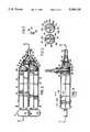
- FIG. 1is an isometric exploded, view of a medical lavage syringe device of this invention and further including waste and source containers and tubes to be used with the lavage device;
- FIG. 2is a top, partially cross-sectional, view of the lavage apparatus of FIG. 1 taken on line 2--2 in FIG. 4;
- FIG. 3is a bottom view of a tab which is part of the lavage syringe device of FIG. 1;
- FIG. 4is a side, partially sectional, view of the apparatus of FIG. 2, taken on line 4--4;
- FIG. 5is a segmented, partially cross-sectional, view taken on line 5--5 of FIG. 4.
- a lavage apparatus 10is shown in FIG. 1 for use with a supply container 12, a supply tube 14, a waste container 16 and a waste tube 18.
- the lavage apparatus 10comprises a rigid housing 20, a common exchange tube 22, an irrigation plunger 24, an aspiration plunger 26, and a system of seals and valves associated therewith.
- the rigid housing 20is molded as one piece of a medical grade, translucent polycarbonate (LEXAN, a trademark of General Electric) plastic.
- the rigid housing 20has an irrigation cylinder 28 defining an irrigation-cylinder bore 30, an aspiration cylinder 32 defining an aspiration-cylinder bore 34, first and second supporting flanges 36 and 38 holding together first ends of the irrigation and aspiration cylinders 28 and 32, a third flange 40 holding together second ends of the irrigation and aspiration cylinders 28 and 32, an inlet port 42 located near a second end of the irrigation cylinder 28 an outlet port 44 located near a second end of the aspiration cylinder 32, an irrigation check-valve cylinder 46 located at the end of the irrigation cylinder 28 and an aspiration check-valve cylinder 48 located at the second end of the aspiration cylinder 32, and an anti-venturi septum 50 joining the second ends of the irrigation and aspiration check-valve cylinders 46 and 48.
- LEXANtranslucent polycarbonate
- the first, second, and third flanges 36, 38, and 40hold the irrigation cylinder 28 and the aspiration cylinder 32 in a side-by-side, parallel, relationship.
- the bores 30 and 34 of the respective irrigation and aspiration cylinders 28 and 32are the same size, each providing approximately 125 cc's in actual stroke volume when the plungers are withdrawn to stops thereof.
- the inlet and outlet ports 42 and 44are close to the second ends 52 of the irrigation and aspiration cylinders 28 and 32 in the form of small, equal sized, valve cylinders extending perpendicular to axes of the irrigation and aspiration cylinders 28 and 32. This increases the turbulence of fluid flow allowing for increased mixing and dissolution of aspirated contents thereby reducing valve clogging.
- the equal sized irrigation and aspiration check-valve cylinders 46 and 48are connected to their respective irrigation and aspiration cylinders 28 and 32 by tapered bonnets 54 and 56, respectively so as to be close to, and parallel with one another.
- the circumference of the check-valve cylinders 46 and 48is about half that of the irrigation and aspiration cylinders 28 and 32 and their axes are offset from those of the irrigation and aspiration cylinders 28 and 32 so that the irrigation and aspiration check-valve cylinders 46 and 48 are close to one another with their bores aligned with the irrigation and aspiration cylinder bores 30 and 34.
- the septum 50has an irrigation baffle 58 and an aspiration baffle 60, each of which is semi-circular in cross-sectional shape. These baffles intersect at an outer tip 62 which forms a U-shaped line.
- the septum baffles 58 and 60are only positioned on the inside sides of the check valve cylinders 46 and 48 so as to guide fluid from and to the check-valve cylinders 46 and 48.
- a fourth flange 64interconnects the outer ends of the check-valve cylinders 46 and 48 and forms an oval with these outer ends.
- the plungers 24 and 26are molded to be identical, each having shafts comprised of crossed longitudinal ribs 69a-d (for the irrigation plunger) and 68a-d (for the aspiration plunger) supported circumferentially by circumferential ribs 70. Also molded integral therewith are finger-engaging portions 72 and seal mounting ribs 74. Seal-mounting ribs 74 are separated from stop or last circumferential ribs 70' by a space 76 into which internally directed ribs (not shown) of seals 80 are inserted for holding the seals thereon. Each seal 80 has a cone-shaped end 82 with small ridges 84 thereon. There are three cylinder-bore contacting rings 83a, b, and c on the outer surface thereof.
- the finger-engaging portions 72 of the plungers 24 and 26are respectively turned so that they provide mirror images, one of the other.
- the finger-engaging portions 72are not geometrical, being flat at first sides 86 thereof and rounded at second sides 88 thereof. The reason for this is so that the first sides 86 can be as close together, between two adjacent fingers, as possible where it is desirable to operate the syringes simultaneously.
- these finger engaging portionsare designed to allow easy use of one of the plungers or both as is desired. This allows one to "prime the pump", so to speak, with the irrigation half of the system upon beginning use of the lavage apparatus.
- the common exchange tube 22is oblong, or oval, in cross section to thereby form an oblong chamber 91 in which fluid flows to and from the irrigation and aspiration cylinders 28 and 32.
- the common exchange tube 22includes an apron portion 90, a manifold portion 92, a common nozzle portion 94, and an attachment ridge 96.
- the attachment ridge 96is of a size to sealingly fit about the side-by-side irrigation and aspiration check-valve cylinders 46 and 48 and the fourth flange 64 which joins them. In use, these members are held together by sonic welding or by an adhesive.
- the apron portion 90makes the entire apparatus more streamlined in appearance and for handling, however, it is not necessary for operation of the lavage apparatus.
- the manifold portion 92encloses and seals with outer ends 98 and 100 of the irrigation and aspiration check-valve cylinders 46 and 48 as well as the septum 50, as can be seen in FIG. 2, so that all material flowing to and from the outer ends 98 and 100 are guided by the septum 50 and the manifold portion 92. Similarly, all fluids flowing to and from the manifold portion 92 flow through the common nozzle 94. It should be noted that the septum 50 is so arranged and designed that fluid streams flowing from the irrigation check-valve cylinder 46 will be directed into the nozzle 94 and fluid flowing from the nozzle 94 will be directed to the aspiration check-valve cylinder 48 without restriction and without causing undue turbulence.
- the U-shaped outer tip line 62particularly aids in avoiding undue cross mixing by not causing a venturi restriction to create a negative pressure in the manifold portion 92 which improperly opens a check-valve. Sidewalls of the septum 50 press against interior surfaces of the manifold at 101 to create a seal therebetween.
- an irrigation check valve 102has a cylinder outer wall with a cross-wall carrying a resilient membrane 104 thereon which flexes open when pressure is exerted from the irrigation-cylinder bore 30 toward the nozzle 94 but closes when pressure is exerted in the opposite direction.
- An aspiration check valve 106 in the aspiration check-valve cylinder 48operates in a similar but opposite manner.
- An inlet check valve 108with an attached membrane 110, allows fluid to flow into the irrigation cylinder 28, but does not allow flow from the irrigation cylinder 28.
- an outlet check-valve 112allows fluid flow from the aspiration cylinder 32, however, it does not allow flow therein.
- Funnel-like inlet and outlet adaptors 116 and 118are respectively attached to the inlet port 42 and the outlet port 44.
- inlet and outlet ports 42 and 44are each restricted by a shelf 119 (FIG. 4) which makes an actual port opening 120 have an elongated (semicircular) shape and have the same cross-sectional area as the bore of the nozzle 94.
- the approximate matching of these sizesbalances pressures within the system so as to avoid improper opening of the check-valves during operation and thereby avoid cross mixing of contaminated and pure fluids.
- the shelves 119have the additional purpose of creating elongated port openings 120 which allow the openings 120 to be fully sealed by the relatively-close-together contacting rings 83a, b, and c when the respective plungers 24 and 26 are fully depressed, as shown in FIG. 4.
- the shelf 119 at the aspiration outlet port 44tends to break up solids which might otherwise jam the membrane 114.
- the shelves 119allow rather large membrane type check-valves to be used with necessarily smaller valve openings 120. These larger check valves are not as vulnerable to jamming as smaller ones.
- All of the various rigid components of this inventioncan be constructed of a rigid hard resinous plastic such as polycarbonate (LEXAN).
- a rigid hard resinous plasticsuch as polycarbonate (LEXAN).
- the rigid housing 20, the two plungers 24 and 26, the common exchange tube 22, and the various check valve cylinders 102, 106, 108, and 112 and the inlet and outlet adaptors 116 and 118are molded of hard resinous plastic.
- all of the check-valvesare the same size so as not to require more than one mold for these elements.
- the plunger seal 80 and the various check-valve membranesare molded, or purchased off-the-shelf.
- the plunger seals 80are attached to plungers 24 and 26 and the various check-valve membranes are attached to knobs on the check-valve cylinders 102, 106, 108, and 112.
- the check valve cylindersare then attached by press fitting or sonic welding in their respective positions to the rigid housing 20 as is depicted in the exploded view of FIG. 1. Thereafter, the attachment ridge 96 of the common exchange tube 22 is sealingly adhered to the irrigation and aspiration check valve cylinders 46 and 48 and the flange 64 which adjoins these two ridges.
- the various valvescannot be easily serviced, but that is not necessary since the lavage apparatus is designed to be a single use, disposable product.
- the lavage apparatus 10To utilize the lavage apparatus 10 one places a lavage liquid in the supply container 12 which is joined via a supply tube 14 and the inlet adaptor 116 to the inlet port 42.
- the waste container 16is similarly attached via tube 18 and outlet adaptor 118 to the outlet port 44.
- the lavage solutionis to be instilled into a body cavity, left for a short length of time and then sucked out.
- a tube(not shown) is attached to the nozzle 94 of the common exchange tube 22 which is inserted through an opening in the human body into an organ to be lavaged. Where fluid from more than one irrigation cylinder 28 is to be inserted into the organ before any is aspirated, the aspiration plunger 26 is inserted fully into the aspiration cylinder 32 as is depicted in FIGS. 2 and 4.
- the aspiration plunger seal 80completely seals the opening 120 of the outlet port 44.
- the irrigation plunger 24is pulled outwardly to cause a vacuum in the irrigation cylinder 28.
- This vacuumrespectfully opens the membrane 110 of the inlet check-valve 108 and closes the membrane 104 of the irrigation check-valve 102.
- fluidis sucked from the supply container 12 into the irrigation cylinder 28.
- the irrigation plunger 24is driven into the irrigation cylinder 28 which closes the inlet check valve 108, opens the irrigation check valve 102, and drives fluid out of the irrigation cylinder 28 into the manifold portion 92 of the common exchange tube 22 and out the nozzle 94 of the common exchange tube 22.
- the irrigation baffle 58 of the septum 50guides this fluid to ensure that it enters the nozzle 94 rather than being driven through the aspiration check-valve cylinder 48 to open the aspiration check-valve 106 and thereby drive the plunger 26 from its blocking position.
- the irrigator plunger 24is moved in and out until the body cavity has the right amount of fluid in it.
- the irrigation plunger 24is driven fully into the irrigation cylinder 28 so that seal 80 covers the openings 120 of the inlet port 42 thereby not allowing flow of fluid through this port.
- the aspiration plungeris pulled out and pushed in, thereby sucking contaminated fluid from the body organ through the nozzle 94, and the aspiration check-valve cylinder 48, into the aspiration cylinder 32, driving the contaminated waste fluid out of the outlet port 44 into the waste container.
- the pressures applied at each of these by the equal size plungers 24 and 26are approximately equal, there being only a small drop across each of the various valves to cause them to act as check valves in the appropriate directions.
- the shape of the U-shaped outer tip line 62 of the anti-venturi septum 50does not cause undue venturi or eddy effects which create undue changes in pressure at the nozzle 94 to improperly open the irrigation and aspiration check valves 102 and 106 to cause a mixing.
- each of these tabs 122a-dcomprises a relatively thin base plate 124 having spaced spring legs 126 extending from a bottom surface thereof.
- the base plate 124is slightly rounded to the circular outer surface contours of the irrigation and aspiration cylinders 28 and 32.
- the irrigation and aspiration cylinders 28 and 32each have tab openings 128a, b, c and d therein for receiving the spring legs 126 of the tabs.
- the spring legs 126include ramp surfaces 130 (FIG. 5) and shoulders 132 such that when the spring legs 126 of a tab are inserted through a tab opening 128, the ramp surfaces engage end edges of the tab opening 128 forcing the spring legs 126 inwardly until the shoulders 132 are inside a cylinder bore.
- the spring legs 126can spring outwardly so that the shoulders 132 engage housing walls thereby preventing the tabs 122 from being removed from the tab openings 128.
- the tabs 122a-dare mounted in their respective tab openings 128a-d, their legs project into the appropriate bore 30 or 34, as can be seen in FIGS. 4 and 5.
- Another feature of the tab legs 126is that when they are viewed from their bottom ends, as is depicted in FIG. 3, they have angled camming surfaces 133 whose purpose is described below.
- the irrigation and aspiration plungers 24 and 26are also constructed somewhat differently in this improvement.
- intermediate circumferential ribs 134a, b, c and d for these plungersare notched at 136 adjacent a top longitudinal rib 68a and 69a.
- the longitudinal ribs 68a-d of the aspiration plungerdiffer from the longitudinal ribs 69a-d of the irrigation plunger 24 in that they include longitudinal notches 140 on outer edges thereof. Positions of the longitudinal notches 140 corresponding to axial, or longitudinal, positions of tab openings 128a and b in the aspiration cylinder 32.
- the apparatusis assembled by inserting the seals 80 and the stop, or last, circumferential ribs 70' of the plungers 24 and 26 into the open ends of the irrigation and aspiration cylinders 28 and 32 and shoving them past all of the tab openings 128a-d.
- the spring legs 126 of the guide/lock/stop tabs 122a-dare then inserted into their respective tab openings 128a-d until they are locked in place by the shoulders 132 on the spring legs 126. While the tabs 122 are being inserted into the tab openings 128, the irrigation and aspiration plungers 24 and 22 are held in rotative orientation as depicted in FIG.
- the longitudinal ribs 68a and 69aare directed upwardly toward the middle of the tab openings 128 so that when the spring legs 126 are inserted into the tab openings 128a-d their legs straddle the respective longitudinal ribs 68a and 69a.
- the longitudinal rib 68a of the aspiration plunger 26is positioned between the spring legs 126 of the guide/lock/stop tab 122a. In this position, the aspiration plunger 26 cannot normally be rotated because its longitudinal rib 168a engages the legs 126.
- the legs 126then are aligned with the longitudinal notches 140 in the longitudinal ribs which allows clearance for the aspiration plunger 26 to be rotated.
- one of the camming surfaces 135 of the spring legs 126contacts one of the latching cam surfaces 142 of the intermediate circumferential rib 134a to thereby lock the aspiration plunger 26 in position.
- the irrigation plunger 24can then be pulled in and out without fear of the aspiration plunger 26 moving from this fully inserted position in which its seal 80 covers the opening 120 of the outlet port 44.
- irrigating fluidcannot be transferred directly from the irrigation cylinder 28 through the outlet port 44, but rather, when the irrigation plunger 24 is worked, evacuation fluid is driven through the common exchange tube 22 into a cavity to be evacuated.
- the guide/lock/stop tabs 122a and calso serve as stops inasmuch as their spring legs 126 contact end or stop circumferential ribs 70' of the irrigation and aspiration plungers 24 and 26 to prevent these plungers from being removed from their respective cylinders.
- the intermediate circumferential ribs 134a-dhave circumferential notches 136 therein for allowing these intermediate ribs to pass longitudinally past the various tabs.
- the improvements described hereinmaintain the rotational orientations of the irrigation and aspiration plungers 24 and 26 unless the aspiration plunger 26 is rotated to be locked in a fully inserted position in which a seal 80 covers the outlet port 44. It should be noted that the irrigation plunger 24 need not be locked inasmuch as when the aspiration plunger 26 is independently operated, the irrigation plunger 24 is sucked to a fully inserted position in which its seal 80 covers the inlet port 42.
Landscapes
- Health & Medical Sciences (AREA)
- Heart & Thoracic Surgery (AREA)
- Hematology (AREA)
- Anesthesiology (AREA)
- Biomedical Technology (AREA)
- Engineering & Computer Science (AREA)
- Vascular Medicine (AREA)
- Life Sciences & Earth Sciences (AREA)
- Animal Behavior & Ethology (AREA)
- General Health & Medical Sciences (AREA)
- Public Health (AREA)
- Veterinary Medicine (AREA)
- Pulmonology (AREA)
- Infusion, Injection, And Reservoir Apparatuses (AREA)
- External Artificial Organs (AREA)
Abstract
Description
Claims (29)
Priority Applications (8)
| Application Number | Priority Date | Filing Date | Title |
|---|---|---|---|
| US07/584,141US5049135A (en) | 1990-09-18 | 1990-09-18 | Medical lavage apparatus |
| DE69128091TDE69128091T2 (en) | 1990-09-18 | 1991-09-17 | MEDICAL WASHING DEVICE |
| EP91918090AEP0549708B1 (en) | 1990-09-18 | 1991-09-17 | Medical lavage apparatus |
| PCT/US1991/006592WO1992004925A1 (en) | 1990-09-18 | 1991-09-17 | Medical lavage apparatus |
| CA002088069ACA2088069C (en) | 1990-09-18 | 1991-09-17 | Medical lavage apparatus |
| AT91918090TATE159659T1 (en) | 1990-09-18 | 1991-09-17 | MEDICAL WASHING DEVICE |
| JP3516974AJP2977612B2 (en) | 1990-09-18 | 1991-09-17 | Improved medical cleaning equipment |
| AU87333/91AAU644561B2 (en) | 1990-09-18 | 1991-09-17 | Medical lavage apparatus |
Applications Claiming Priority (1)
| Application Number | Priority Date | Filing Date | Title |
|---|---|---|---|
| US07/584,141US5049135A (en) | 1990-09-18 | 1990-09-18 | Medical lavage apparatus |
Publications (1)
| Publication Number | Publication Date |
|---|---|
| US5049135Atrue US5049135A (en) | 1991-09-17 |
Family
ID=24336084
Family Applications (1)
| Application Number | Title | Priority Date | Filing Date |
|---|---|---|---|
| US07/584,141Expired - LifetimeUS5049135A (en) | 1990-09-18 | 1990-09-18 | Medical lavage apparatus |
Country Status (7)
| Country | Link |
|---|---|
| US (1) | US5049135A (en) |
| EP (1) | EP0549708B1 (en) |
| JP (1) | JP2977612B2 (en) |
| AT (1) | ATE159659T1 (en) |
| CA (1) | CA2088069C (en) |
| DE (1) | DE69128091T2 (en) |
| WO (1) | WO1992004925A1 (en) |
Cited By (44)
| Publication number | Priority date | Publication date | Assignee | Title |
|---|---|---|---|---|
| US5116315A (en)* | 1989-10-03 | 1992-05-26 | Hemaedics, Inc. | Biological syringe system |
| US5254086A (en)* | 1992-07-31 | 1993-10-19 | Ballard Medical Products | Medical lavage apparatus and methods |
| US5290259A (en)* | 1993-02-18 | 1994-03-01 | Ultradent Products, Inc. | Double syringe delivery system |
| FR2706774A1 (en)* | 1993-06-23 | 1994-12-30 | Achard Michel | Medical apparatus intended in particular for spraying and/or suction of a fluid substance |
| FR2706775A1 (en)* | 1993-06-23 | 1994-12-30 | Achard Michel | Tip intended for an apparatus for dispensing and/or sampling a fluid substance, in particular in the medical field, and apparatus allowing its implementation |
| US5407424A (en)* | 1993-02-24 | 1995-04-18 | Scimed Life Systems, Inc. | Angioplasty perfusion pump |
| WO1995016478A1 (en)* | 1993-12-14 | 1995-06-22 | U.S. Medical Instruments, Inc. | Retractable syringe with a closed barrel |
| WO1995034334A1 (en)* | 1994-06-15 | 1995-12-21 | Interventional Research Technologies, Inc. | Locking device for syringe or like instrument |
| US5656035A (en)* | 1995-04-25 | 1997-08-12 | Avoy; Donald R. | Refillable fibrinogen dispensing kit |
| US5749968A (en)* | 1993-03-01 | 1998-05-12 | Focal, Inc. | Device for priming for improved adherence of gels to substrates |
| US5989237A (en) | 1997-12-04 | 1999-11-23 | Baxter International Inc. | Sliding reconstitution device with seal |
| US6022339A (en) | 1998-09-15 | 2000-02-08 | Baxter International Inc. | Sliding reconstitution device for a diluent container |
| US6047861A (en)* | 1998-04-15 | 2000-04-11 | Vir Engineering, Inc. | Two component fluid dispenser |
| US6331172B1 (en) | 1997-04-14 | 2001-12-18 | Baxter International Inc. | Applicator for dispensing measured quantities with use of controlled suction |
| US6527749B1 (en)* | 1997-12-19 | 2003-03-04 | United States Surgical Corporation | Two component dispenser system |
| US6582415B1 (en) | 1998-09-15 | 2003-06-24 | Thomas A. Fowles | Sliding reconstitution device for a diluent container |
| US20040159715A1 (en)* | 2003-02-03 | 2004-08-19 | Leach Michael D. | Spray applicator |
| US20040167617A1 (en)* | 2001-01-26 | 2004-08-26 | Voellmicke John C. | Graft delivery system |
| US20050054995A1 (en)* | 2003-09-09 | 2005-03-10 | Barzell Winston E. | System and method for irrigation and tissue evacuation and collection |
| US6884230B1 (en) | 1998-03-09 | 2005-04-26 | Baxter International Inc. | Dispensing head for a tissue sealant applicator and process of use |
| US6921380B1 (en) | 1998-10-01 | 2005-07-26 | Baxter International Inc. | Component mixing catheter |
| US7025755B2 (en) | 1997-04-14 | 2006-04-11 | Baxter International Inc. | Medical suctioning apparatus and methods of use |
| US7074216B2 (en) | 1998-09-15 | 2006-07-11 | Baxter International Inc. | Sliding reconstitution device for a diluent container |
| US20060253082A1 (en)* | 2005-04-21 | 2006-11-09 | Mcintosh Kevin D | Fluid dispenser |
| US7358505B2 (en) | 1998-09-15 | 2008-04-15 | Baxter International Inc. | Apparatus for fabricating a reconstitution assembly |
| US7425209B2 (en) | 1998-09-15 | 2008-09-16 | Baxter International Inc. | Sliding reconstitution device for a diluent container |
| WO2009064466A1 (en)* | 2007-11-14 | 2009-05-22 | Perfusion Partners & Associates, Inc. | Dual lumen syringe |
| US20090234323A1 (en)* | 2008-03-17 | 2009-09-17 | Jesse Bunch | Multi-mode syringe |
| US20090266918A1 (en)* | 2008-04-25 | 2009-10-29 | Jason Fortier | Silicone spray tip |
| US7641851B2 (en) | 2003-12-23 | 2010-01-05 | Baxter International Inc. | Method and apparatus for validation of sterilization process |
| US20100010495A1 (en)* | 2006-04-26 | 2010-01-14 | David Foster | Medical Treatment Material Delivery Apparatus |
| US20100048991A1 (en)* | 2008-08-22 | 2010-02-25 | Fujifilm Corporation | Automatic-return syringe and endoscope device using the syringe |
| US20100065660A1 (en)* | 2008-09-12 | 2010-03-18 | Les Hull | Spray applicator |
| US20100096481A1 (en)* | 2008-04-25 | 2010-04-22 | Les Hull | Self-cleaning spray tip |
| US7766900B2 (en) | 2005-02-21 | 2010-08-03 | Biomet Manufacturing Corp. | Method and apparatus for application of a fluid |
| US8182769B2 (en) | 2008-04-04 | 2012-05-22 | Biomet Biologics, Llc | Clean transportation system |
| US8518272B2 (en) | 2008-04-04 | 2013-08-27 | Biomet Biologics, Llc | Sterile blood separating system |
| US9561327B2 (en) | 2013-03-15 | 2017-02-07 | Merit Medical Systems, Inc. | Lockable syringe assemblies and related devices and methods |
| US20170158413A1 (en)* | 2012-11-08 | 2017-06-08 | Sulzer Mixpac Ag | Cartridge for at least two flowable components |
| US10309430B2 (en) | 2012-08-10 | 2019-06-04 | Confluent Surgical, Inc. | Pneumatic actuation assembly |
| US10952709B2 (en) | 2014-04-04 | 2021-03-23 | Hyperbranch Medical Technology, Inc. | Extended tip spray applicator for two-component surgical sealant, and methods of use thereof |
| US20210315677A1 (en)* | 2020-04-08 | 2021-10-14 | Juan Arrazolo | Double Barreled Injector Assembly |
| US11350945B2 (en) | 2017-11-13 | 2022-06-07 | Merit Medical Systems, Inc. | Staged deflation syringe systems and associated methods |
| US11890405B2 (en) | 2016-11-27 | 2024-02-06 | Albert A. Mikhail | Multi-port syringe system and method for use with a urinary catheter |
Citations (16)
| Publication number | Priority date | Publication date | Assignee | Title |
|---|---|---|---|---|
| US13975A (en)* | 1855-12-25 | buhler | ||
| US386603A (en)* | 1888-07-24 | Stomach-pump | ||
| US1496126A (en)* | 1922-06-09 | 1924-06-03 | Joseph W Livingstone | Syringe |
| US3159312A (en)* | 1962-09-28 | 1964-12-01 | Budd Co | Dispensing device for mixing two viscous fluids |
| US3398743A (en)* | 1965-10-20 | 1968-08-27 | Shalit Shimon | Closed system irrigating apparatus for viscus organs |
| US3450134A (en)* | 1966-07-05 | 1969-06-17 | Medizintechnik Willgerodt Veb | Injection device |
| US3818907A (en)* | 1973-04-23 | 1974-06-25 | M Walton | Double cylinder lavage syringe |
| US3828980A (en)* | 1972-11-06 | 1974-08-13 | Chem Dev Corp | Dispenser for precisely metered dispensing of viscous fluids |
| US4044757A (en)* | 1976-01-14 | 1977-08-30 | The Kendall Company | Cholangiography device and method |
| US4046166A (en)* | 1975-06-14 | 1977-09-06 | Wibau (Westdeutsche Industrie- Und Strassenbau-Maschinen Gesellschaft M.B.H.) | Reciprocating valve for a double piston concrete pump |
| US4054137A (en)* | 1976-07-02 | 1977-10-18 | Seung Joon Lee | Irrigator for body cavities |
| US4260077A (en)* | 1979-10-04 | 1981-04-07 | Aelco Corporation | Dual separable dispenser |
| US4662868A (en)* | 1985-07-26 | 1987-05-05 | University Of Pittsburgh | Syringe apparatus and valve employed therein |
| US4857056A (en)* | 1988-07-06 | 1989-08-15 | Sherwood Medical Company | Auto-flush syringe pump |
| US4883471A (en)* | 1988-08-16 | 1989-11-28 | Braginetz Paul A | Disposable shielded medical syringe |
| US4979942A (en)* | 1989-10-16 | 1990-12-25 | Johnson & Johnson Medical, Inc. | Two component syringe delivery system |
Family Cites Families (4)
| Publication number | Priority date | Publication date | Assignee | Title |
|---|---|---|---|---|
| GB599348A (en)* | 1945-09-17 | 1948-03-10 | Alojzy Piechaczek | Improvements relating to surgical and medical syringes and pumps |
| DE7912969U1 (en)* | 1979-05-04 | 1979-09-27 | Dr. Eduard Fresenius, Chemisch- Pharmazeutische Industrie Kg, 6380 Bad Homburg | INJECTION SYRINGE |
| EP0208975A3 (en)* | 1985-07-04 | 1987-05-20 | Antonio Gomez Gomez | Syringe for producing vacuum-controlled suction |
| US4842581A (en)* | 1987-09-11 | 1989-06-27 | Davis Richard C | Medical lavage apparatus |
- 1990
- 1990-09-18USUS07/584,141patent/US5049135A/ennot_activeExpired - Lifetime
- 1991
- 1991-09-17WOPCT/US1991/006592patent/WO1992004925A1/enactiveIP Right Grant
- 1991-09-17JPJP3516974Apatent/JP2977612B2/ennot_activeExpired - Fee Related
- 1991-09-17EPEP91918090Apatent/EP0549708B1/ennot_activeExpired - Lifetime
- 1991-09-17DEDE69128091Tpatent/DE69128091T2/ennot_activeExpired - Fee Related
- 1991-09-17CACA002088069Apatent/CA2088069C/ennot_activeExpired - Fee Related
- 1991-09-17ATAT91918090Tpatent/ATE159659T1/ennot_activeIP Right Cessation
Patent Citations (16)
| Publication number | Priority date | Publication date | Assignee | Title |
|---|---|---|---|---|
| US386603A (en)* | 1888-07-24 | Stomach-pump | ||
| US13975A (en)* | 1855-12-25 | buhler | ||
| US1496126A (en)* | 1922-06-09 | 1924-06-03 | Joseph W Livingstone | Syringe |
| US3159312A (en)* | 1962-09-28 | 1964-12-01 | Budd Co | Dispensing device for mixing two viscous fluids |
| US3398743A (en)* | 1965-10-20 | 1968-08-27 | Shalit Shimon | Closed system irrigating apparatus for viscus organs |
| US3450134A (en)* | 1966-07-05 | 1969-06-17 | Medizintechnik Willgerodt Veb | Injection device |
| US3828980A (en)* | 1972-11-06 | 1974-08-13 | Chem Dev Corp | Dispenser for precisely metered dispensing of viscous fluids |
| US3818907A (en)* | 1973-04-23 | 1974-06-25 | M Walton | Double cylinder lavage syringe |
| US4046166A (en)* | 1975-06-14 | 1977-09-06 | Wibau (Westdeutsche Industrie- Und Strassenbau-Maschinen Gesellschaft M.B.H.) | Reciprocating valve for a double piston concrete pump |
| US4044757A (en)* | 1976-01-14 | 1977-08-30 | The Kendall Company | Cholangiography device and method |
| US4054137A (en)* | 1976-07-02 | 1977-10-18 | Seung Joon Lee | Irrigator for body cavities |
| US4260077A (en)* | 1979-10-04 | 1981-04-07 | Aelco Corporation | Dual separable dispenser |
| US4662868A (en)* | 1985-07-26 | 1987-05-05 | University Of Pittsburgh | Syringe apparatus and valve employed therein |
| US4857056A (en)* | 1988-07-06 | 1989-08-15 | Sherwood Medical Company | Auto-flush syringe pump |
| US4883471A (en)* | 1988-08-16 | 1989-11-28 | Braginetz Paul A | Disposable shielded medical syringe |
| US4979942A (en)* | 1989-10-16 | 1990-12-25 | Johnson & Johnson Medical, Inc. | Two component syringe delivery system |
Cited By (85)
| Publication number | Priority date | Publication date | Assignee | Title |
|---|---|---|---|---|
| US5116315A (en)* | 1989-10-03 | 1992-05-26 | Hemaedics, Inc. | Biological syringe system |
| US5254086A (en)* | 1992-07-31 | 1993-10-19 | Ballard Medical Products | Medical lavage apparatus and methods |
| WO1994003218A1 (en)* | 1992-07-31 | 1994-02-17 | Ballard Medical Products | Medical lavage apparatus and methods |
| US5330424A (en)* | 1992-07-31 | 1994-07-19 | Ballard Medical Products | Medical lavage apparatus and methods |
| AU663407B2 (en)* | 1992-07-31 | 1995-10-05 | Ballard Medical Products | Medical lavage apparatus and methods |
| US5290259A (en)* | 1993-02-18 | 1994-03-01 | Ultradent Products, Inc. | Double syringe delivery system |
| US5407424A (en)* | 1993-02-24 | 1995-04-18 | Scimed Life Systems, Inc. | Angioplasty perfusion pump |
| US5749968A (en)* | 1993-03-01 | 1998-05-12 | Focal, Inc. | Device for priming for improved adherence of gels to substrates |
| FR2706774A1 (en)* | 1993-06-23 | 1994-12-30 | Achard Michel | Medical apparatus intended in particular for spraying and/or suction of a fluid substance |
| FR2706775A1 (en)* | 1993-06-23 | 1994-12-30 | Achard Michel | Tip intended for an apparatus for dispensing and/or sampling a fluid substance, in particular in the medical field, and apparatus allowing its implementation |
| US5685864A (en)* | 1993-11-22 | 1997-11-11 | Interventional Research Technologies | Locking device for aspirator, syringe or like instrument |
| WO1995016478A1 (en)* | 1993-12-14 | 1995-06-22 | U.S. Medical Instruments, Inc. | Retractable syringe with a closed barrel |
| WO1995034334A1 (en)* | 1994-06-15 | 1995-12-21 | Interventional Research Technologies, Inc. | Locking device for syringe or like instrument |
| US5656035A (en)* | 1995-04-25 | 1997-08-12 | Avoy; Donald R. | Refillable fibrinogen dispensing kit |
| US7025755B2 (en) | 1997-04-14 | 2006-04-11 | Baxter International Inc. | Medical suctioning apparatus and methods of use |
| US6331172B1 (en) | 1997-04-14 | 2001-12-18 | Baxter International Inc. | Applicator for dispensing measured quantities with use of controlled suction |
| US6063068A (en) | 1997-12-04 | 2000-05-16 | Baxter International Inc. | Vial connecting device for a sliding reconstitution device with seal |
| US6852103B2 (en) | 1997-12-04 | 2005-02-08 | Baxter International Inc. | Sliding reconstitution device with seal |
| US5989237A (en) | 1997-12-04 | 1999-11-23 | Baxter International Inc. | Sliding reconstitution device with seal |
| US6071270A (en) | 1997-12-04 | 2000-06-06 | Baxter International Inc. | Sliding reconstitution device with seal |
| US6090092A (en) | 1997-12-04 | 2000-07-18 | Baxter International Inc. | Sliding reconstitution device with seal |
| US6090091A (en) | 1997-12-04 | 2000-07-18 | Baxter International Inc. | Septum for a sliding reconstitution device with seal |
| US6159192A (en) | 1997-12-04 | 2000-12-12 | Fowles; Thomas A. | Sliding reconstitution device with seal |
| US6019750A (en) | 1997-12-04 | 2000-02-01 | Baxter International Inc. | Sliding reconstitution device with seal |
| US6610040B1 (en) | 1997-12-04 | 2003-08-26 | Baxter International Inc. | Sliding reconstitution device with seal |
| US6527749B1 (en)* | 1997-12-19 | 2003-03-04 | United States Surgical Corporation | Two component dispenser system |
| US6884230B1 (en) | 1998-03-09 | 2005-04-26 | Baxter International Inc. | Dispensing head for a tissue sealant applicator and process of use |
| US6047861A (en)* | 1998-04-15 | 2000-04-11 | Vir Engineering, Inc. | Two component fluid dispenser |
| US6113583A (en) | 1998-09-15 | 2000-09-05 | Baxter International Inc. | Vial connecting device for a sliding reconstitution device for a diluent container |
| US7425209B2 (en) | 1998-09-15 | 2008-09-16 | Baxter International Inc. | Sliding reconstitution device for a diluent container |
| US8226627B2 (en) | 1998-09-15 | 2012-07-24 | Baxter International Inc. | Reconstitution assembly, locking device and method for a diluent container |
| US7358505B2 (en) | 1998-09-15 | 2008-04-15 | Baxter International Inc. | Apparatus for fabricating a reconstitution assembly |
| US6875203B1 (en) | 1998-09-15 | 2005-04-05 | Thomas A. Fowles | Vial connecting device for a sliding reconstitution device for a diluent container |
| US6582415B1 (en) | 1998-09-15 | 2003-06-24 | Thomas A. Fowles | Sliding reconstitution device for a diluent container |
| US6890328B2 (en) | 1998-09-15 | 2005-05-10 | Baxter International Inc. | Sliding reconstitution device for a diluent container |
| US6022339A (en) | 1998-09-15 | 2000-02-08 | Baxter International Inc. | Sliding reconstitution device for a diluent container |
| US7074216B2 (en) | 1998-09-15 | 2006-07-11 | Baxter International Inc. | Sliding reconstitution device for a diluent container |
| US6921380B1 (en) | 1998-10-01 | 2005-07-26 | Baxter International Inc. | Component mixing catheter |
| US7175336B2 (en) | 2001-01-26 | 2007-02-13 | Depuy Acromed, Inc. | Graft delivery system |
| US20040167617A1 (en)* | 2001-01-26 | 2004-08-26 | Voellmicke John C. | Graft delivery system |
| US20040159715A1 (en)* | 2003-02-03 | 2004-08-19 | Leach Michael D. | Spray applicator |
| US7077339B2 (en) | 2003-02-03 | 2006-07-18 | Biomet, Inc. | Spray applicator |
| US7172579B2 (en) | 2003-09-09 | 2007-02-06 | Civco Medical Instruments Co., Inc. | System and method for irrigation and tissue evacuation and collection |
| US20070213666A1 (en)* | 2003-09-09 | 2007-09-13 | Civco Medical Instruments Co., Inc. | System and method for irrigation and tissue evacuation and collection |
| US20050054995A1 (en)* | 2003-09-09 | 2005-03-10 | Barzell Winston E. | System and method for irrigation and tissue evacuation and collection |
| US8022375B2 (en) | 2003-12-23 | 2011-09-20 | Baxter International Inc. | Method and apparatus for validation of sterilization |
| US7641851B2 (en) | 2003-12-23 | 2010-01-05 | Baxter International Inc. | Method and apparatus for validation of sterilization process |
| US9028457B2 (en) | 2005-02-21 | 2015-05-12 | Biomet Biologics, Llc | Method and apparatus for application of a fluid |
| US8444620B2 (en) | 2005-02-21 | 2013-05-21 | Biomet Biologics, Llc | Method and apparatus for application of a fluid |
| US7766900B2 (en) | 2005-02-21 | 2010-08-03 | Biomet Manufacturing Corp. | Method and apparatus for application of a fluid |
| US7635343B2 (en)* | 2005-04-21 | 2009-12-22 | Arteriocyte Medical Systems, Inc. | Fluid dispenser |
| US20060253082A1 (en)* | 2005-04-21 | 2006-11-09 | Mcintosh Kevin D | Fluid dispenser |
| US8088099B2 (en)* | 2005-04-21 | 2012-01-03 | Arteriocyte Medical Systems, Inc. | Fluid dispenser |
| US20100076399A1 (en)* | 2005-04-21 | 2010-03-25 | Arteriocyte Medical Systems, Inc. | Fluid dispenser |
| US20100010495A1 (en)* | 2006-04-26 | 2010-01-14 | David Foster | Medical Treatment Material Delivery Apparatus |
| US8696678B2 (en)* | 2006-04-26 | 2014-04-15 | Summit Medical Limited | Medical treatment material delivery apparatus |
| WO2009064466A1 (en)* | 2007-11-14 | 2009-05-22 | Perfusion Partners & Associates, Inc. | Dual lumen syringe |
| US20090234323A1 (en)* | 2008-03-17 | 2009-09-17 | Jesse Bunch | Multi-mode syringe |
| US9504816B2 (en)* | 2008-03-17 | 2016-11-29 | Syringetech Llc | Multi-mode syringe |
| US9211487B2 (en) | 2008-04-04 | 2015-12-15 | Biomet Biologics, Llc | Sterile blood separating system |
| US8182769B2 (en) | 2008-04-04 | 2012-05-22 | Biomet Biologics, Llc | Clean transportation system |
| US8518272B2 (en) | 2008-04-04 | 2013-08-27 | Biomet Biologics, Llc | Sterile blood separating system |
| US8876021B2 (en) | 2008-04-25 | 2014-11-04 | Confluent Surgical, Inc. | Silicone spray tip |
| US8408480B2 (en) | 2008-04-25 | 2013-04-02 | Confluent Surgical, Inc. | Self-cleaning spray tip |
| US8387899B2 (en) | 2008-04-25 | 2013-03-05 | Confluent Surgical, Inc. | Silicone spray tip |
| US20090266918A1 (en)* | 2008-04-25 | 2009-10-29 | Jason Fortier | Silicone spray tip |
| US8033483B2 (en) | 2008-04-25 | 2011-10-11 | Confluent Surgical Inc. | Silicone spray tip |
| US20100096481A1 (en)* | 2008-04-25 | 2010-04-22 | Les Hull | Self-cleaning spray tip |
| US20100048991A1 (en)* | 2008-08-22 | 2010-02-25 | Fujifilm Corporation | Automatic-return syringe and endoscope device using the syringe |
| US8403834B2 (en)* | 2008-08-22 | 2013-03-26 | Fujifilm Corporation | Automatic return syringe with ventilation paths for air and suction ports |
| US20100065660A1 (en)* | 2008-09-12 | 2010-03-18 | Les Hull | Spray applicator |
| US9700290B2 (en) | 2008-09-12 | 2017-07-11 | Confluent Surgical, Inc. | Spray applicator |
| US8210453B2 (en) | 2008-09-12 | 2012-07-03 | Confluent Surgical, Inc. | Spray applicator |
| US8616468B2 (en) | 2008-09-12 | 2013-12-31 | Covidien Lp | Spray applicator |
| US9517478B2 (en) | 2008-09-12 | 2016-12-13 | Confluent Surgical, Inc. | Spray applicator |
| US10092280B2 (en) | 2008-09-12 | 2018-10-09 | Confluent Surgical, Inc. | Spray applicator |
| US9101946B2 (en) | 2008-09-12 | 2015-08-11 | Confluent Surgical, Inc. | Spray applicator |
| US10309430B2 (en) | 2012-08-10 | 2019-06-04 | Confluent Surgical, Inc. | Pneumatic actuation assembly |
| US20170158413A1 (en)* | 2012-11-08 | 2017-06-08 | Sulzer Mixpac Ag | Cartridge for at least two flowable components |
| US9561327B2 (en) | 2013-03-15 | 2017-02-07 | Merit Medical Systems, Inc. | Lockable syringe assemblies and related devices and methods |
| US10952709B2 (en) | 2014-04-04 | 2021-03-23 | Hyperbranch Medical Technology, Inc. | Extended tip spray applicator for two-component surgical sealant, and methods of use thereof |
| US11890405B2 (en) | 2016-11-27 | 2024-02-06 | Albert A. Mikhail | Multi-port syringe system and method for use with a urinary catheter |
| US11350945B2 (en) | 2017-11-13 | 2022-06-07 | Merit Medical Systems, Inc. | Staged deflation syringe systems and associated methods |
| US20210315677A1 (en)* | 2020-04-08 | 2021-10-14 | Juan Arrazolo | Double Barreled Injector Assembly |
| US11540910B2 (en)* | 2020-04-08 | 2023-01-03 | Juan Arrazolo | Double barreled injector assembly |
Also Published As
| Publication number | Publication date |
|---|---|
| JP2977612B2 (en) | 1999-11-15 |
| EP0549708B1 (en) | 1997-10-29 |
| DE69128091T2 (en) | 1998-06-10 |
| WO1992004925A1 (en) | 1992-04-02 |
| CA2088069A1 (en) | 1992-03-19 |
| EP0549708A1 (en) | 1993-07-07 |
| JPH06501405A (en) | 1994-02-17 |
| ATE159659T1 (en) | 1997-11-15 |
| EP0549708A4 (en) | 1994-05-11 |
| DE69128091D1 (en) | 1997-12-04 |
| CA2088069C (en) | 2002-01-08 |
Similar Documents
| Publication | Publication Date | Title |
|---|---|---|
| US5049135A (en) | Medical lavage apparatus | |
| US5330424A (en) | Medical lavage apparatus and methods | |
| US4842581A (en) | Medical lavage apparatus | |
| US7361164B2 (en) | Multi-outlet medical dispensing device | |
| US5176658A (en) | Valve assembly for use in medical devices | |
| US3957052A (en) | Pumping-syringe | |
| US5449145A (en) | Valve device for controlling flows in surgical applications | |
| US4872866A (en) | Medical lavage apparatus | |
| FI89008C (en) | Control valve for intravenously administered fluids | |
| US5658144A (en) | Dental syringe | |
| KR20180019184A (en) | Merge device for single or multiple containers | |
| NO180669B (en) | A valve assembly | |
| US20060093989A1 (en) | Dental therapeutic device | |
| US4662868A (en) | Syringe apparatus and valve employed therein | |
| US5163926A (en) | Suction metering and mixing device | |
| AU644561B2 (en) | Medical lavage apparatus | |
| WO1993017733A1 (en) | Composite irrigation and suction probe | |
| EP3177341B1 (en) | Disposable wound irrigation device | |
| US633805A (en) | Syringe. | |
| HK1106462A (en) | Multi-outlet medical dispensing device |
Legal Events
| Date | Code | Title | Description |
|---|---|---|---|
| AS | Assignment | Owner name:CODE BLUE MEDICAL CORPORATION, FLORIDA Free format text:ASSIGNMENT OF ASSIGNORS INTEREST.;ASSIGNOR:DAVIS, RICHARD C.;REEL/FRAME:005455/0056 Effective date:19900912 | |
| FEPP | Fee payment procedure | Free format text:PAYOR NUMBER ASSIGNED (ORIGINAL EVENT CODE: ASPN); ENTITY STATUS OF PATENT OWNER: LARGE ENTITY | |
| STCF | Information on status: patent grant | Free format text:PATENTED CASE | |
| AS | Assignment | Owner name:BALLARD MEDICAL PRODUCTS, A CORPORATION OF UT, UTA Free format text:ASSIGNMENT OF ASSIGNORS INTEREST.;ASSIGNOR:CODE BLUE MEDICAL CORPORATION, A FL CORP.;REEL/FRAME:006125/0638 Effective date:19920512 | |
| FEPP | Fee payment procedure | Free format text:PAT HLDR NO LONGER CLAIMS SMALL ENT STAT AS SMALL BUSINESS (ORIGINAL EVENT CODE: LSM2); ENTITY STATUS OF PATENT OWNER: LARGE ENTITY | |
| FPAY | Fee payment | Year of fee payment:4 | |
| FPAY | Fee payment | Year of fee payment:8 | |
| FPAY | Fee payment | Year of fee payment:12 | |
| AS | Assignment | Owner name:KIMBERLY-CLARK WORLDWIDE, INC., WISCONSIN Free format text:ASSIGNMENT OF ASSIGNORS INTEREST;ASSIGNOR:BALLARD MEDICAL PRODUCTS, INC.;REEL/FRAME:019805/0150 Effective date:20070910 |