US5048698A - Office accessory mounting rail - Google Patents
Office accessory mounting railDownload PDFInfo
- Publication number
- US5048698A US5048698AUS07/536,398US53639890AUS5048698AUS 5048698 AUS5048698 AUS 5048698AUS 53639890 AUS53639890 AUS 53639890AUS 5048698 AUS5048698 AUS 5048698A
- Authority
- US
- United States
- Prior art keywords
- rail
- mounting
- elongated
- office
- sheet material
- Prior art date
- Legal status (The legal status is an assumption and is not a legal conclusion. Google has not performed a legal analysis and makes no representation as to the accuracy of the status listed.)
- Expired - Fee Related
Links
Images


Classifications
- A—HUMAN NECESSITIES
- A47—FURNITURE; DOMESTIC ARTICLES OR APPLIANCES; COFFEE MILLS; SPICE MILLS; SUCTION CLEANERS IN GENERAL
- A47G—HOUSEHOLD OR TABLE EQUIPMENT
- A47G1/00—Mirrors; Picture frames or the like, e.g. provided with heating, lighting or ventilating means
- A47G1/16—Devices for hanging or supporting pictures, mirrors, or the like
- A47G1/1686—Picture rails; Accessories therefor, e.g. hooks or the like, specially adapted for use with picture rails
- A—HUMAN NECESSITIES
- A47—FURNITURE; DOMESTIC ARTICLES OR APPLIANCES; COFFEE MILLS; SPICE MILLS; SUCTION CLEANERS IN GENERAL
- A47F—SPECIAL FURNITURE, FITTINGS, OR ACCESSORIES FOR SHOPS, STOREHOUSES, BARS, RESTAURANTS OR THE LIKE; PAYING COUNTERS
- A47F5/00—Show stands, hangers, or shelves characterised by their constructional features
- A47F5/08—Show stands, hangers, or shelves characterised by their constructional features secured to the wall, ceiling, or the like; Wall-bracket display devices
- A47F5/0807—Display panels, grids or rods used for suspending merchandise or cards supporting articles; Movable brackets therefor
- A47F5/0846—Display panels or rails with elongated channels; Sliders, brackets, shelves, or the like, slidably attached therein
Definitions
- the present inventiongenerally relates to apparatus for suspending and holding office accessories, paper, and other items within reach of an office worker seated at an office furniture system.
- the present inventionspecifically relates to accessory mounting rails for connection to office furniture and for display, suspension, and holding of diverse articles adjacent to the work surface for immediate and convenient use by an office worker.
- Previous office furniture and office systems designershave sought to provide means and apparatus for conveniently locating a variety of papers and other objects in a position conveniently close to an office worker seated near an article of office furniture such as a desk.
- Such prior art devicesinclude clipboards, which are not self-supporting but rather must be propped against a vertical object to enable the information on the clipboard to be viewed and to prevent the clipboard from collapsing.
- Another prior art deviceis the bulletin board, typical examples of which are not only aesthetically unappealing, but generally must be fixed in a single place within the office environment. Bulletin boards are also not suited to holding articles other than paper and cardboard, due to the relatively low holding strength of pushpins and thumbtacks used in conjunction with bulletin boards.
- the prior artappears deficient in not including a compact, attractively designed, versatile and space-efficient apparatus for holding, displaying, and securing diverse office supply articles, papers, and related items.
- an elongated office accessory mounting railfor securement between two spaced-apart stanchions or other vertical members having accessory brackets for receiving the ends of the mounting rail.
- the railis mounted onto mounting brackets each demountably secured to the shelf accessory bracket preferably provided on the rear vertical wall of the stanchions.
- Each mounting bracketincludes plural teeth for engagement in notches in the vertical brackets of the stanchions, and each bracket further includes plural mounting tabs for engagement with complimentary notches provided on the rear face of the accessory mounting rail.
- the rail mounting bracketsare each secured using the plural teeth in the stanchion brackets, and the notches provided in each end of the accessory bar are mounted on the rail mounting bracket mounting tabs.
- the mounting railincludes front and rear horizontally elongated vertically oriented plates joined approximately at their mid-point by an interior, horizontally oriented elongated web member.
- the rear surface of the railis provided with two mounting flanges which cooperate and forcibly fit into the mounting tabs provided on the rail mounting brackets.
- the railfurther includes one forward-facing hook plate on which plural accessories may be hung, and a second, backward-facing hook plate for hangingly securing accessories below and behind the rail.
- the railfurther includes a downwardly-angled channel defined by the front and rear structural plates and the downward-facing surface of the web plate.
- Plural steel rod segmentsare placed in the channel to retain documents. In operation, pushing a piece of sheet material upward into the channel forces the steel rod segment to float upward into the channel. When the sheet of paper is released, gravity forces the steel rod segment downward and thereby presses the sheet material between the steel rod segment exterior and a shoulder rib on the interior surface of the rear rail plate.
- One object of the present inventionis to provide unitary means for hanging office accessories within easy reach of an office worker seated at modular office furniture and the like, and means for releasibly retaining in place sheet materials such as paper in the same apparatus used to hang such accessories.
- a further object of the present inventionis to provide means for hanging and releasibly displaying accessories and sheet material which is adaptable to various modular office furniture having opposed, spaced-apart vertical brackets.
- a further object of the present inventionis to provide means for releasibly retaining sheet material in a position easily accessible by a office worker seated at typical modular office furniture, wherein one sheet or piece of such sheet material may be removed from the retaining device without simultaneously releasing all other sheet material retained in the device.
- Still a further object of the present inventionis to provide unitary means for hanging plural office accessories and releasibly displaying and holding sheet material which is lightweight, easily manufactured, structurally strong, and visually attractive.
- FIG. 1is a perspective view of an office furniture system showing an accessory mounting rail according to the present invention mounted between two structural stanchions of the system.
- FIG. 2is an exploded perspective view of one end of an accessory rail of the present invention, one embodiment of a mounting bracket of the present invention, and part of one of the structural stanchions of FIG. 1.
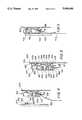
- FIG. 3is a section view taken along lines 3--3 of FIG. 2.
- FIG. 4is a schematic representation of a rail according to the present invention showing an office accessory about to be mounted on the rail and sheet material being inserted into the rail.
- FIG. 5is a schematic representation of a rail according to the present invention showing an accessory in mounted position on the rail and a sheet of material in retained position in the rail.
- an office furniture I0 system 5including a desk or work unit 7 and a pair of opposed, spaced-apart vertical structural stanchions 100.
- the present inventionrelates to apparatus for securement to and use in conjunction with stanchions and office furniture systems of the type disclosed in the co-pending United States patent application entitled “Furniture Stanchions With Unitary Power Routing System", filed on even date herewith and incorporated herein by reference.
- the stanchions 100each include a vertical, inward-facing bracket 180 such as a conventional shelf bracket to which plural accessories may be attached in cantilever fashion.
- the opposing inward-facing bracketsmay also be connected by a single device suspended between the two brackets.
- such an accessory suspended between the two bracketsmay include an office accessory and document rail 600 according to the present invention.
- a rail 600includes a single, elongated piece of structurally strong material 601, preferably extruded aluminum, having two ends 600' and 600" each secured to a mounting plate 500 which is interfitted with a stanchion bracket 180.
- the mounting plate 500' of FIG. 2serves as an adapter enabling the rail 600 according to the present invention to be used with many different modular office furniture systems.
- a mounting plate 500' usable with the rail 600 according to the present inventionis shown in FIGS. 2 through 5, and includes a generally rectangular bracket body 500 having a downwardly extending, rectangular bracket arm 502 secured to one lower corner 516 of body 500.
- the bracket arm 502is provided on one side with an inwardly-facing lower tooth 506, comprising an outwardly-extending lower tooth arm 520 secured at a right angle to bracket arm 502, and a generally triangular-shaped tooth point 522 secured to the bottom edge of arm 520.
- the tooth point 522is tapered away from bracket arm 502 and thereby defines a lower grip notch 510 which is generally triangular, the triangle being oriented vertically opposite the triangular orientation of tooth point 522.
- Tooth point 526is generally configured as a downwardly-pointing triangular segment, and is spaced apart from body 500 to define an upper, upwardly-pointing triangular grip notch 508.
- Notches 508 and 510, and also teeth 504 and 506,are shaped to permit teeth 504 and 506 to be interfitted with the elongated, rectangular openings provided in a standard shelf bracket such as openings 181 of bracket 180.
- bracket body 500the teeth 504 and 506 are simultaneously pressed into a pair of axially aligned elongated openings 181 in the bracket 18 on stanchions 100.
- the bracket body 500is then pulled down, forcing notches 508 and 510 against the upper edges of the elongated rectangular openings 181 provided in the bracket 180.
- This arrangementcauses the bracket body 500 and the entire mounting plate 500' to be force-fit into the bracket 180, assuring a rigid, firm securement of the plate 500' to the bracket 180.
- Bracket body 500is further provided with an upper mounting tab 512 and a lower mounting tab 514 respectively located in the upper and lower inboard corners of bracket body 500.
- the tabs 512 and 514are punched or lanced outward from the same planer material which forms body 500, such that open windows 512' and 514', each resembling an inverted "U", surround tabs 512 and 514.
- the U-shaped windows 512' and 514'are created as a result of the punching or lancing process used in manufacturing.
- tabs 512 and 514When tabs 512 and 514 are punched outwardly during the manufacturing process, they define an upwardly-facing, narrow grip channel 528 which separates each of the tabs 512 and 514 from the remainder of a plane defined by the front surface of body 500, as shown in FIG. 3. Channels 528 are disposed to enable a force-fit securement of the rear portion of a mounting rail according to the present invention.
- rear flanges 606 and 608 provided on the rail 600 according to the present inventionmay be force-fit into channels 528 on each of tabs 512 and 514, enabling the rail 600 to forcibly fit into and be held by friction between tabs 512 and 514 and the body 500.
- the accessory mounting rail 600 of the present inventionpreferably comprises a single extruded aluminum rail 601 comprising integrally formed front plate 602 and rear plate 604. Plates 602 and 604 are joined at approximately their mid-point by interior web plate 610. The lower end 605 of plate 604 terminates in a rear-facing hook plate 616 having an elongated, upwardly protruding lip 617 on which plural accessories may be hung. Plate 604 is secured to web plate 610 at an obtuse angle, such that plate 604 is downwardly outwardly angled with respect to the vertical orientation of bracket body 500 shown in FIG. 3. This angled orientation of plate 604 permits lower end 605 to be separated from bracket body 500 by clearance space sufficient to clear hook 616.
- Plates 602 and 604are joined at their upper ends by an upper web strip 612. Secured to the approximate mid-point of strip 612 is a generally vertical, horizontally elongated upper arm 622. The upper end 623 of arm 622 terminates in an inwardly-facing curved top shield 620. In conjunction with the upwardly-protruding hanger 618, which hanger 618 is secured to the upper end 603 of front plate 602, shield 620 defines a generally "C"-shaped channel 621 which provides clearance and mounting space for demountable accessories 400, 460, and 470 of FIG. 1 such as the mini bulletin board 400 shown in FIG. 4. As FIG. 4 indicates in detail, the bulletin board 400 includes a rear surface 402 provided with a downwardly-facing hook 404. The hook 404 defines a grip channel 406 which cooperates with and snugly fits onto the protrusion 618 when the accessory is mounted on the rail 600. When bulletin board 400 is mounted in rail 600, the bulletin board assumes the position shown in FIG. 5.
- Two downwardly-facing rail securement flanges 608 and 606are secured, respectively, to the upper end 623 of plate 622 and to the mid-point 609 of rear plate 604.
- Flanges 608 and 606are constructed having a thickness slightly greater than channel 528 which separates tabs 512 and 514 from bracket body 500.
- flange 608is forced into space 528 behind tab 512, and flange 606 is simultaneously forced into the space 528 behind tab 514.
- the rail 600thereafter assumes the mounted position shown in FIGS. 3, 4, and 5, with flanges 608 and 606 firmly seated between tabs 512 and 514 and bracket body 500.
- a downward-facing channel 642which in the cross-section of FIG. 3 generally resembles an inverted "U", is defined by the lower end 640 of plate 602, web plate 610, and the lower end 605 of plate 604.
- a steel rod segment 700is movably mounted in channel 642, and is loosely retained in place by shoulder 628 provided adjacent lower end 605 of plate 604. Thus, rod segment 700 is free to move upward into channel 642, but ordinarily gravity forces rod 700 downward and against shoulder 628 and lower end 640 of plate 602.
- Rod 700serves as a sheet retainer for flat, sheet material 450 such as note paper, card stock, or other flat sheet material common in the office environment.
- sheet material 450such as note paper, card stock, or other flat sheet material common in the office environment.
- the sheet material 450 shown in FIG. 4is pushed upward into channel 642, thereby displacing rod 700 and forcing rod 700 further upward into channel 642.
- shoulder 628acts as a guide for the sheet material, directing it upward into channel 642 and locating the sheet material between rod 700 and shoulder 628.
- the position of shoulder 628induces a slight curl 452 or role in the upper end 452 of sheet material 450 as the sheet 450 is inserted between rod 700 and shoulder 628. This curl 452 ensures that sufficient friction exists between the rod 700, material 450, and the shoulder 628 to retain the sheet material 450 in place.
- an office workermay pull downward on sheet 450.
- the frictional force holding the sheet in place between rod 700 and shoulder 628is overcome, forcing rod 700 to rotate about its longitudinal axis and allowing sheet 450 to be pulled from between rod 700 and shoulder 628.
- the rail 600extends between and is supported by two brackets 500'mounted in two stanchions 100 as shown in FIG. 1.
- Stanchions 100 shown in FIG. 1are typically separated by the width of a desk top 20, which may be several feet wide. Accordingly, a rail 600 of the present invention itself may have an overall length of several feet or more. Consequently, steel rods 700 of the present invention do not run the entire length of rail 600 but are preferably constructed in approximately one-foot lengths, to enable one or more pieces of sheet material 450 to be inserted into or removed from the rail 600 without displacing or disturbing other sheets secured in the rail 600 at other locations. Thus, if the rail 600 shown in FIG.
- bracket body 500may be altered to enable the bracket 500 to cooperate with mounting brackets provided on modular office furniture of different design.
- the bracket 500can serve as an adapter enabling a rail 600 to be mounted in different types and configurations of office furniture. Therefore, it should be understood that, within the scope of the appended claims, the invention may be practiced otherwise than as specifically described.
Landscapes
- Tables And Desks Characterized By Structural Shape (AREA)
Abstract
Description
Claims (9)
Priority Applications (1)
| Application Number | Priority Date | Filing Date | Title |
|---|---|---|---|
| US07/536,398US5048698A (en) | 1990-06-12 | 1990-06-12 | Office accessory mounting rail |
Applications Claiming Priority (1)
| Application Number | Priority Date | Filing Date | Title |
|---|---|---|---|
| US07/536,398US5048698A (en) | 1990-06-12 | 1990-06-12 | Office accessory mounting rail |
Publications (1)
| Publication Number | Publication Date |
|---|---|
| US5048698Atrue US5048698A (en) | 1991-09-17 |
Family
ID=24138326
Family Applications (1)
| Application Number | Title | Priority Date | Filing Date |
|---|---|---|---|
| US07/536,398Expired - Fee RelatedUS5048698A (en) | 1990-06-12 | 1990-06-12 | Office accessory mounting rail |
Country Status (1)
| Country | Link |
|---|---|
| US (1) | US5048698A (en) |
Cited By (68)
| Publication number | Priority date | Publication date | Assignee | Title |
|---|---|---|---|---|
| US5205524A (en)* | 1988-04-19 | 1993-04-27 | Capitol Hardware Manufacturing Co., Inc. | Adjustable bracket |
| US5227954A (en)* | 1991-10-18 | 1993-07-13 | Epson Portland, Inc. | Arrangement for mounting disk drive in drive dock |
| USD341077S (en) | 1991-12-26 | 1993-11-09 | American Trading And Production Corporation | Bracket for supporting office desk trays |
| EP0571229A1 (en)* | 1992-05-22 | 1993-11-24 | Quartet Manufacturing Company | Panel system |
| USD349234S (en) | 1991-12-26 | 1994-08-02 | American Trading And Production Corporation | Bracket for supporting office desk trays |
| US5363974A (en)* | 1991-12-26 | 1994-11-15 | American Trading And Production Corporation | Stackable desk tray assembly |
| USD385481S (en)* | 1996-07-09 | 1997-10-28 | Lynk, Inc. | Hanger |
| US5695073A (en)* | 1996-04-10 | 1997-12-09 | Lynk, Inc. | Hanging shoe rack |
| USD397565S (en) | 1997-08-20 | 1998-09-01 | Lynk, Inc. | Over the door sliding hook |
| USD411701S (en) | 1997-08-20 | 1999-06-29 | Lynk, Inc. | Modular over the door sliding hook |
| US6050426A (en)* | 1997-03-19 | 2000-04-18 | Leurdijk; Jan B. | Storage track system |
| USD427823S (en)* | 1998-05-28 | 2000-07-11 | Herman Miller, Inc. | Support stanchion |
| US6138841A (en)* | 1999-01-08 | 2000-10-31 | Lynk, Inc. | Hanging rack for sports equipment |
| US6152313A (en)* | 1997-08-20 | 2000-11-28 | Lynk, Inc. | Clothes hanger with sliding hooks |
| USD439084S1 (en) | 1998-05-28 | 2001-03-20 | Herman Miller, Inc. | Support stanchion |
| US6206206B1 (en) | 1999-04-30 | 2001-03-27 | Haworth, Inc. | Rail-mounted hanging file arrangement |
| US6227384B1 (en) | 1999-04-30 | 2001-05-08 | Haworth, Inc. | Slotted divider arrangement |
| USD445456S1 (en) | 1999-04-30 | 2001-07-24 | Haworth, Inc. | Support rail assembly for office accessories |
| US6267338B1 (en) | 1999-04-30 | 2001-07-31 | Haworth, Inc. | Support rail assembly for office accessories |
| US6302366B1 (en) | 1999-04-30 | 2001-10-16 | Haworth, Inc. | Grip clip |
| US6464087B1 (en) | 1999-08-26 | 2002-10-15 | Lynk, Inc. | Hanging shoe rack with double loop shoe retaining arrangement |
| US6464086B1 (en) | 1999-08-26 | 2002-10-15 | Lynk, Inc. | Hanging modular storage unit |
| US20030005654A1 (en)* | 2001-05-18 | 2003-01-09 | Weber Jeffrey A. | Workstation |
| US6533127B1 (en) | 1999-08-19 | 2003-03-18 | Lynk, Inc. | Over-door shoe racks |
| US6550875B1 (en) | 2000-04-28 | 2003-04-22 | Haworth, Inc. | Storage cabinet removably mounted on a worksurface by support stanchions |
| US6557310B2 (en) | 2000-06-09 | 2003-05-06 | Smed International, Inc. | Interior space-dividing wall system |
| US6609285B1 (en) | 1999-10-01 | 2003-08-26 | Herman Miller, Inc. | Process for manufacturing a support |
| US20030189393A1 (en)* | 2000-06-06 | 2003-10-09 | Draudt Gregg R. | Furniture accessory kit for portable computers and the like |
| US20040046932A1 (en)* | 2000-04-18 | 2004-03-11 | Ocular Sciences, Inc. | Ophthalmic lenses and compositions and methods for producing same |
| US20040045916A1 (en)* | 1999-08-19 | 2004-03-11 | Klein Richard B. | Over-door shoe racks |
| FR2844687A1 (en)* | 2002-09-20 | 2004-03-26 | Clen | Suspended accessory for office furniture comprises rear wall with horizontally spaced vertical slots which receive removable fastener, made from metallic sheet, having retaining part engaging slot and hook for hooking on support structure |
| US20050011844A1 (en)* | 2003-06-25 | 2005-01-20 | Elfa International Ab | Fastening device |
| US20050097800A1 (en)* | 2003-07-09 | 2005-05-12 | Pitcher David E. | Elongated poster support arrangement |
| US20070166277A1 (en)* | 2002-12-31 | 2007-07-19 | Mcmanus Samuel P | Polymeric reagents comprising a ketone or a related functional group |
| US20080078728A1 (en)* | 2006-10-03 | 2008-04-03 | American Greetings Corporation | Retail display for greeting cards |
| USD580745S1 (en) | 2008-03-14 | 2008-11-18 | Illinois Tool Works Inc. | Hook |
| USD580744S1 (en) | 2008-03-14 | 2008-11-18 | Illinois Tool Works Inc. | Hook |
| US20080297015A1 (en)* | 2007-05-30 | 2008-12-04 | Steelcase Inc. | Storage unit back stop and method |
| USD589278S1 (en) | 2008-03-14 | 2009-03-31 | Illinois Tool Works Inc. | Holder |
| USD589728S1 (en) | 2008-03-14 | 2009-04-07 | Illinois Tool Works Inc. | Receptacle |
| USD592422S1 (en) | 2007-06-06 | 2009-05-19 | Steelcase Development Corporation | Cabinet |
| US20090230067A1 (en)* | 2008-03-14 | 2009-09-17 | Kevin Bruce Shaha | Storage System |
| USD604978S1 (en) | 2008-03-14 | 2009-12-01 | Illinois Tool Works Inc. | Wall mountable rail system |
| USD604979S1 (en) | 2008-03-14 | 2009-12-01 | Illinois Tool Works Inc. | Rail system arm |
| USD610832S1 (en) | 2007-06-08 | 2010-03-02 | Steelcase Inc. | Cabinet |
| USD619881S1 (en) | 2008-03-14 | 2010-07-20 | Illinois Tool Works Inc. | Hook |
| US20110192948A1 (en)* | 2010-02-11 | 2011-08-11 | Kuang-Ping Chen | Shelf bracket for goods shelves |
| WO2011119847A2 (en) | 2010-03-24 | 2011-09-29 | Middle Atlantic Products, Inc. | Video screen mounting system |
| US8087735B1 (en) | 2007-05-31 | 2012-01-03 | Steelcase Inc. | Free standing furniture kit and method of assembly |
| US8276523B2 (en) | 2008-05-28 | 2012-10-02 | Steelcase Inc. | Worksurface assembly |
| US8573415B2 (en) | 2010-05-03 | 2013-11-05 | Illinois Tool Works Inc. | Storage system |
| US8667908B2 (en) | 2010-06-02 | 2014-03-11 | Steelcase Inc. | Frame type table assemblies |
| US8689705B2 (en) | 2010-06-02 | 2014-04-08 | Steelcase, Inc. | Reconfigurable table assemblies |
| US9185974B2 (en) | 2010-06-02 | 2015-11-17 | Steelcase Inc. | Frame type workstation configurations |
| US9210999B2 (en) | 2010-06-02 | 2015-12-15 | Steelcase Inc. | Frame type table assemblies |
| WO2016178610A1 (en)* | 2015-05-04 | 2016-11-10 | Göran Hansson | Profile device for hanging of objects like shelves and pictures at a wall |
| US10039374B2 (en) | 2016-05-13 | 2018-08-07 | Steelcase Inc. | Multi-tiered workstation assembly |
| US10299589B1 (en)* | 2018-07-09 | 2019-05-28 | Shenter Enterprise Co., Ltd. | Frame hooking and combining structure |
| US10306981B2 (en) | 2016-12-02 | 2019-06-04 | Altria Client Services Llc | Universal mounting system (UMS) and method of installing thereof |
| US10334970B2 (en)* | 2016-12-02 | 2019-07-02 | Altria Client Services Llc | Adaptive merchandising platform (AMP) mounting system and method of installing thereof |
| US20190290002A1 (en)* | 2018-03-23 | 2019-09-26 | Hni Technologies Inc. | Systems, brackets, and methods for mounting storage structures to office work surfaces |
| US10517392B2 (en) | 2016-05-13 | 2019-12-31 | Steelcase Inc. | Multi-tiered workstation assembly |
| US10575641B1 (en) | 2018-08-20 | 2020-03-03 | Rehau Industries, L.L.C. | Shelving system, shelf unit, and method of assembling shelf unit |
| US10799041B1 (en)* | 2019-03-26 | 2020-10-13 | Tag Hardware Systems Ltd. | Wall mounted organizer rack |
| US11109672B2 (en) | 2018-11-20 | 2021-09-07 | Squaregrove, LLC | Vertically adjustable desk with under-carriage mounting system |
| US20220104638A1 (en)* | 2020-10-07 | 2022-04-07 | Christopher B. Peng | Modular flower bed systems |
| US12022960B2 (en) | 2021-05-04 | 2024-07-02 | Knoll, Inc. | Furniture, charging port assembly, and method of assembling same |
| US12376677B1 (en) | 2012-10-10 | 2025-08-05 | Steelcase Inc. | Ergonomic seating system, tilt-lock control and remote powering method and apparatus |
Citations (14)
| Publication number | Priority date | Publication date | Assignee | Title |
|---|---|---|---|---|
| GB399876A (en)* | 1932-04-15 | 1933-10-16 | Linoleum Mfg Company Ltd | Improvements in apparatus for displaying linoleum, carpets, wallpapers and other flat sheets |
| US3168954A (en)* | 1963-01-10 | 1965-02-09 | Mohawk Prec Corp | Hanger for flexible sheet material |
| US3399429A (en)* | 1967-07-06 | 1968-09-03 | Goodman Robert | Clamping device |
| US3591013A (en)* | 1967-01-03 | 1971-07-06 | Mohawk Precision Corp | Hanger for flexible sheet material |
| US3675782A (en)* | 1970-07-15 | 1972-07-11 | James M Dudley | Hanger for sheet material |
| US3814368A (en)* | 1972-09-12 | 1974-06-04 | M Freed | Wall mounted sheet holder |
| US4085848A (en)* | 1977-01-10 | 1978-04-25 | Kenji Tsuge | Holder device for suspending articles such as paper and the like |
| US4085867A (en)* | 1976-07-26 | 1978-04-25 | Peter Van Nest Heller | Dispensing containers and holder |
| US4215840A (en)* | 1978-10-10 | 1980-08-05 | Rapid Mounting & Finishing Company | Display system |
| US4401222A (en)* | 1981-06-08 | 1983-08-30 | Westinghouse Electric Corp. | Support rail |
| US4467925A (en)* | 1981-11-30 | 1984-08-28 | Harry Ratzloff | Wheelbarrow and garden tool storage rack |
| US4771897A (en)* | 1987-10-02 | 1988-09-20 | Jackson Ho | Key hanging device |
| US4773545A (en)* | 1984-05-04 | 1988-09-27 | Jones Graham R | Gripping devices for holding elements therein |
| US4869378A (en)* | 1988-08-29 | 1989-09-26 | Hospital Systems, Inc. | Mounting rail for hospital appliances and bracket |
- 1990
- 1990-06-12USUS07/536,398patent/US5048698A/ennot_activeExpired - Fee Related
Patent Citations (14)
| Publication number | Priority date | Publication date | Assignee | Title |
|---|---|---|---|---|
| GB399876A (en)* | 1932-04-15 | 1933-10-16 | Linoleum Mfg Company Ltd | Improvements in apparatus for displaying linoleum, carpets, wallpapers and other flat sheets |
| US3168954A (en)* | 1963-01-10 | 1965-02-09 | Mohawk Prec Corp | Hanger for flexible sheet material |
| US3591013A (en)* | 1967-01-03 | 1971-07-06 | Mohawk Precision Corp | Hanger for flexible sheet material |
| US3399429A (en)* | 1967-07-06 | 1968-09-03 | Goodman Robert | Clamping device |
| US3675782A (en)* | 1970-07-15 | 1972-07-11 | James M Dudley | Hanger for sheet material |
| US3814368A (en)* | 1972-09-12 | 1974-06-04 | M Freed | Wall mounted sheet holder |
| US4085867A (en)* | 1976-07-26 | 1978-04-25 | Peter Van Nest Heller | Dispensing containers and holder |
| US4085848A (en)* | 1977-01-10 | 1978-04-25 | Kenji Tsuge | Holder device for suspending articles such as paper and the like |
| US4215840A (en)* | 1978-10-10 | 1980-08-05 | Rapid Mounting & Finishing Company | Display system |
| US4401222A (en)* | 1981-06-08 | 1983-08-30 | Westinghouse Electric Corp. | Support rail |
| US4467925A (en)* | 1981-11-30 | 1984-08-28 | Harry Ratzloff | Wheelbarrow and garden tool storage rack |
| US4773545A (en)* | 1984-05-04 | 1988-09-27 | Jones Graham R | Gripping devices for holding elements therein |
| US4771897A (en)* | 1987-10-02 | 1988-09-20 | Jackson Ho | Key hanging device |
| US4869378A (en)* | 1988-08-29 | 1989-09-26 | Hospital Systems, Inc. | Mounting rail for hospital appliances and bracket |
Cited By (102)
| Publication number | Priority date | Publication date | Assignee | Title |
|---|---|---|---|---|
| US5205524A (en)* | 1988-04-19 | 1993-04-27 | Capitol Hardware Manufacturing Co., Inc. | Adjustable bracket |
| US5227954A (en)* | 1991-10-18 | 1993-07-13 | Epson Portland, Inc. | Arrangement for mounting disk drive in drive dock |
| USD341077S (en) | 1991-12-26 | 1993-11-09 | American Trading And Production Corporation | Bracket for supporting office desk trays |
| USD349234S (en) | 1991-12-26 | 1994-08-02 | American Trading And Production Corporation | Bracket for supporting office desk trays |
| US5363974A (en)* | 1991-12-26 | 1994-11-15 | American Trading And Production Corporation | Stackable desk tray assembly |
| EP0571229A1 (en)* | 1992-05-22 | 1993-11-24 | Quartet Manufacturing Company | Panel system |
| USRE39638E1 (en)* | 1996-04-10 | 2007-05-22 | Lynk, Inc. | Hanging shoe rack |
| US5695073A (en)* | 1996-04-10 | 1997-12-09 | Lynk, Inc. | Hanging shoe rack |
| USD385481S (en)* | 1996-07-09 | 1997-10-28 | Lynk, Inc. | Hanger |
| US6050426A (en)* | 1997-03-19 | 2000-04-18 | Leurdijk; Jan B. | Storage track system |
| USD411701S (en) | 1997-08-20 | 1999-06-29 | Lynk, Inc. | Modular over the door sliding hook |
| US6152313A (en)* | 1997-08-20 | 2000-11-28 | Lynk, Inc. | Clothes hanger with sliding hooks |
| USD397565S (en) | 1997-08-20 | 1998-09-01 | Lynk, Inc. | Over the door sliding hook |
| USD427823S (en)* | 1998-05-28 | 2000-07-11 | Herman Miller, Inc. | Support stanchion |
| USD439084S1 (en) | 1998-05-28 | 2001-03-20 | Herman Miller, Inc. | Support stanchion |
| US6138841A (en)* | 1999-01-08 | 2000-10-31 | Lynk, Inc. | Hanging rack for sports equipment |
| US6227384B1 (en) | 1999-04-30 | 2001-05-08 | Haworth, Inc. | Slotted divider arrangement |
| USD445456S1 (en) | 1999-04-30 | 2001-07-24 | Haworth, Inc. | Support rail assembly for office accessories |
| US6267338B1 (en) | 1999-04-30 | 2001-07-31 | Haworth, Inc. | Support rail assembly for office accessories |
| US6302366B1 (en) | 1999-04-30 | 2001-10-16 | Haworth, Inc. | Grip clip |
| USD453794S1 (en) | 1999-04-30 | 2002-02-19 | Haworth, Inc. | Support rail assembly for office accessories |
| US6435461B1 (en) | 1999-04-30 | 2002-08-20 | Haworth, Inc. | Support rail assembly for office accessories |
| US6206206B1 (en) | 1999-04-30 | 2001-03-27 | Haworth, Inc. | Rail-mounted hanging file arrangement |
| US7025214B2 (en) | 1999-08-19 | 2006-04-11 | Lynk, Inc. | Over-door shoe racks |
| US6926157B2 (en) | 1999-08-19 | 2005-08-09 | Lynk, Inc. | Over-door shoe racks |
| US6533127B1 (en) | 1999-08-19 | 2003-03-18 | Lynk, Inc. | Over-door shoe racks |
| US20060169657A1 (en)* | 1999-08-19 | 2006-08-03 | Klein Richard B | Over-door shoe racks |
| US7021475B2 (en) | 1999-08-19 | 2006-04-04 | Lynk, Inc. | Over-door shoe racks |
| US6793080B2 (en) | 1999-08-19 | 2004-09-21 | Lynk, Inc. | Over-door shoe racks |
| US20040159619A1 (en)* | 1999-08-19 | 2004-08-19 | Klein Richard B. | Over-door shoe racks |
| US6637603B2 (en) | 1999-08-19 | 2003-10-28 | Lynk, Inc. | Over-door shoe racks |
| US20040050809A1 (en)* | 1999-08-19 | 2004-03-18 | Klein Richard B. | Over-door shoe racks |
| US20040045916A1 (en)* | 1999-08-19 | 2004-03-11 | Klein Richard B. | Over-door shoe racks |
| US20040045915A1 (en)* | 1999-08-19 | 2004-03-11 | Klein Richard B. | Over-door shoe racks |
| US6464087B1 (en) | 1999-08-26 | 2002-10-15 | Lynk, Inc. | Hanging shoe rack with double loop shoe retaining arrangement |
| US6464086B1 (en) | 1999-08-26 | 2002-10-15 | Lynk, Inc. | Hanging modular storage unit |
| US6609285B1 (en) | 1999-10-01 | 2003-08-26 | Herman Miller, Inc. | Process for manufacturing a support |
| US20040046932A1 (en)* | 2000-04-18 | 2004-03-11 | Ocular Sciences, Inc. | Ophthalmic lenses and compositions and methods for producing same |
| US6992118B2 (en) | 2000-04-18 | 2006-01-31 | Cooper Vision Inc. | Ophthalmic lenses and compositions and methods for producing same |
| US6550875B1 (en) | 2000-04-28 | 2003-04-22 | Haworth, Inc. | Storage cabinet removably mounted on a worksurface by support stanchions |
| US20030189393A1 (en)* | 2000-06-06 | 2003-10-09 | Draudt Gregg R. | Furniture accessory kit for portable computers and the like |
| US6557310B2 (en) | 2000-06-09 | 2003-05-06 | Smed International, Inc. | Interior space-dividing wall system |
| US20030005654A1 (en)* | 2001-05-18 | 2003-01-09 | Weber Jeffrey A. | Workstation |
| FR2844687A1 (en)* | 2002-09-20 | 2004-03-26 | Clen | Suspended accessory for office furniture comprises rear wall with horizontally spaced vertical slots which receive removable fastener, made from metallic sheet, having retaining part engaging slot and hook for hooking on support structure |
| US20070166277A1 (en)* | 2002-12-31 | 2007-07-19 | Mcmanus Samuel P | Polymeric reagents comprising a ketone or a related functional group |
| US20050011844A1 (en)* | 2003-06-25 | 2005-01-20 | Elfa International Ab | Fastening device |
| US7121417B2 (en)* | 2003-06-25 | 2006-10-17 | Elfa International Ab | Fastening device |
| US20050097800A1 (en)* | 2003-07-09 | 2005-05-12 | Pitcher David E. | Elongated poster support arrangement |
| US7373748B2 (en) | 2003-07-09 | 2008-05-20 | Rose Displays Ltd. | Elongated poster support arrangement |
| US20080078728A1 (en)* | 2006-10-03 | 2008-04-03 | American Greetings Corporation | Retail display for greeting cards |
| US7775379B2 (en)* | 2006-10-03 | 2010-08-17 | American Greetings Corporation | Retail display for greeting cards |
| US8104850B2 (en) | 2007-05-30 | 2012-01-31 | Steelcase Inc. | Furniture storage unit |
| US20080297015A1 (en)* | 2007-05-30 | 2008-12-04 | Steelcase Inc. | Storage unit back stop and method |
| US8087735B1 (en) | 2007-05-31 | 2012-01-03 | Steelcase Inc. | Free standing furniture kit and method of assembly |
| USD592422S1 (en) | 2007-06-06 | 2009-05-19 | Steelcase Development Corporation | Cabinet |
| USD610832S1 (en) | 2007-06-08 | 2010-03-02 | Steelcase Inc. | Cabinet |
| USD580745S1 (en) | 2008-03-14 | 2008-11-18 | Illinois Tool Works Inc. | Hook |
| USD589278S1 (en) | 2008-03-14 | 2009-03-31 | Illinois Tool Works Inc. | Holder |
| USD604979S1 (en) | 2008-03-14 | 2009-12-01 | Illinois Tool Works Inc. | Rail system arm |
| US20090230067A1 (en)* | 2008-03-14 | 2009-09-17 | Kevin Bruce Shaha | Storage System |
| USD619881S1 (en) | 2008-03-14 | 2010-07-20 | Illinois Tool Works Inc. | Hook |
| USD589728S1 (en) | 2008-03-14 | 2009-04-07 | Illinois Tool Works Inc. | Receptacle |
| USD604978S1 (en) | 2008-03-14 | 2009-12-01 | Illinois Tool Works Inc. | Wall mountable rail system |
| USD580744S1 (en) | 2008-03-14 | 2008-11-18 | Illinois Tool Works Inc. | Hook |
| US8066130B2 (en) | 2008-03-14 | 2011-11-29 | Illinois Tool Works Inc. | Storage system |
| US8701568B2 (en) | 2008-05-28 | 2014-04-22 | Steelcase Inc. | Rail and desk with sliding top and power access (C:SCAPE) |
| US8276523B2 (en) | 2008-05-28 | 2012-10-02 | Steelcase Inc. | Worksurface assembly |
| US20110192948A1 (en)* | 2010-02-11 | 2011-08-11 | Kuang-Ping Chen | Shelf bracket for goods shelves |
| EP2550803A4 (en)* | 2010-03-24 | 2016-08-24 | Middle Atlantic Products Inc | Video screen mounting system |
| WO2011119847A2 (en) | 2010-03-24 | 2011-09-29 | Middle Atlantic Products, Inc. | Video screen mounting system |
| US8573415B2 (en) | 2010-05-03 | 2013-11-05 | Illinois Tool Works Inc. | Storage system |
| US8689705B2 (en) | 2010-06-02 | 2014-04-08 | Steelcase, Inc. | Reconfigurable table assemblies |
| US11944194B2 (en) | 2010-06-02 | 2024-04-02 | Steelcase Inc. | Frame type workstation configurations |
| US9210999B2 (en) | 2010-06-02 | 2015-12-15 | Steelcase Inc. | Frame type table assemblies |
| US10681980B2 (en) | 2010-06-02 | 2020-06-16 | Steelcase Inc. | Frame type workstation configurations |
| US11317716B2 (en) | 2010-06-02 | 2022-05-03 | Steelcase Inc. | Frame type workstation configurations |
| US11882934B2 (en) | 2010-06-02 | 2024-01-30 | Steelcase Inc. | Frame type workstation configurations |
| US11930926B2 (en) | 2010-06-02 | 2024-03-19 | Steelcase Inc. | Frame type workstation configurations |
| US9185974B2 (en) | 2010-06-02 | 2015-11-17 | Steelcase Inc. | Frame type workstation configurations |
| US8667908B2 (en) | 2010-06-02 | 2014-03-11 | Steelcase Inc. | Frame type table assemblies |
| US12376677B1 (en) | 2012-10-10 | 2025-08-05 | Steelcase Inc. | Ergonomic seating system, tilt-lock control and remote powering method and apparatus |
| EP3302180A4 (en)* | 2015-05-04 | 2019-03-27 | GH Trap Teknik Sweden AB | Profile device for hanging of objects like shelves and pictures at a wall |
| WO2016178610A1 (en)* | 2015-05-04 | 2016-11-10 | Göran Hansson | Profile device for hanging of objects like shelves and pictures at a wall |
| US10517392B2 (en) | 2016-05-13 | 2019-12-31 | Steelcase Inc. | Multi-tiered workstation assembly |
| US10039374B2 (en) | 2016-05-13 | 2018-08-07 | Steelcase Inc. | Multi-tiered workstation assembly |
| US10306981B2 (en) | 2016-12-02 | 2019-06-04 | Altria Client Services Llc | Universal mounting system (UMS) and method of installing thereof |
| US11707144B2 (en) | 2016-12-02 | 2023-07-25 | Altria Client Services Llc | Method of installing mounting system with support bracket |
| US10888179B2 (en) | 2016-12-02 | 2021-01-12 | Altria Client Services Llc | Support bracket for mounting system |
| US10334970B2 (en)* | 2016-12-02 | 2019-07-02 | Altria Client Services Llc | Adaptive merchandising platform (AMP) mounting system and method of installing thereof |
| US10548417B2 (en) | 2016-12-02 | 2020-02-04 | Altria Client Services Llc | Adaptive merchandising platform (AMP) mounting system and method of installing thereof |
| US11160395B2 (en) | 2016-12-02 | 2021-11-02 | Altria Client Services Llc | Method of making support bracket |
| US11178964B2 (en) | 2016-12-02 | 2021-11-23 | Altria Client Services Llc | Mounting system with horizontally-slideable bracket and support bracket |
| US11864649B2 (en) | 2016-12-02 | 2024-01-09 | Altria Client Services Llc | Method of installing mounting system with insertable brackets and support brackets |
| US20190290002A1 (en)* | 2018-03-23 | 2019-09-26 | Hni Technologies Inc. | Systems, brackets, and methods for mounting storage structures to office work surfaces |
| US11006749B2 (en)* | 2018-03-23 | 2021-05-18 | Hni Technologies Inc. | Systems, brackets, and methods for mounting storage structures to office work surfaces |
| US10299589B1 (en)* | 2018-07-09 | 2019-05-28 | Shenter Enterprise Co., Ltd. | Frame hooking and combining structure |
| US10575641B1 (en) | 2018-08-20 | 2020-03-03 | Rehau Industries, L.L.C. | Shelving system, shelf unit, and method of assembling shelf unit |
| US11109672B2 (en) | 2018-11-20 | 2021-09-07 | Squaregrove, LLC | Vertically adjustable desk with under-carriage mounting system |
| US10799041B1 (en)* | 2019-03-26 | 2020-10-13 | Tag Hardware Systems Ltd. | Wall mounted organizer rack |
| US11751703B2 (en)* | 2020-10-07 | 2023-09-12 | Christopher B. Peng | Modular flower bed systems |
| US20220104638A1 (en)* | 2020-10-07 | 2022-04-07 | Christopher B. Peng | Modular flower bed systems |
| US12022960B2 (en) | 2021-05-04 | 2024-07-02 | Knoll, Inc. | Furniture, charging port assembly, and method of assembling same |
Similar Documents
| Publication | Publication Date | Title |
|---|---|---|
| US5048698A (en) | Office accessory mounting rail | |
| US5775521A (en) | Office organizer | |
| US5678797A (en) | Flush-mount support bracket | |
| US4256043A (en) | Display system for sample articles | |
| US4215840A (en) | Display system | |
| US6206206B1 (en) | Rail-mounted hanging file arrangement | |
| US6792876B2 (en) | Tabletop suspension system | |
| US4026508A (en) | Hanger bracket | |
| US4126230A (en) | Document handling system | |
| US3712698A (en) | Structural support system for drawers and the like | |
| JP2897790B2 (en) | Store sales system | |
| US3965540A (en) | Clip for mounting a crossbar to a bracket | |
| US4949853A (en) | Convertible desktop organizer | |
| GB2090727A (en) | Prong for use in display of merchandise | |
| US5722623A (en) | Upright display assembly | |
| US8091714B2 (en) | Method for displaying merchandise in front of backer material | |
| EP1062896A2 (en) | A display apparatus | |
| US5158186A (en) | Hanging file system | |
| WO1993006583A1 (en) | Product identification tag for flat bar hook | |
| US5393136A (en) | Drawer with convertible filing support system | |
| US7909296B2 (en) | Display with adjustable bracket | |
| JP4612026B2 (en) | Card product display system | |
| US4750625A (en) | Shelf and divider arrangement | |
| US4697710A (en) | Carpet display stand | |
| US5938158A (en) | Desktop support structure |
Legal Events
| Date | Code | Title | Description |
|---|---|---|---|
| AS | Assignment | Owner name:WESTINGHOUSE ELECTRIC CORPORATION, WESTINGHOUSE BU Free format text:ASSIGNMENT OF ASSIGNORS INTEREST.;ASSIGNOR:KONRAD, KARL;REEL/FRAME:005660/0800 Effective date:19910209 | |
| FEPP | Fee payment procedure | Free format text:PAYOR NUMBER ASSIGNED (ORIGINAL EVENT CODE: ASPN); ENTITY STATUS OF PATENT OWNER: LARGE ENTITY | |
| FPAY | Fee payment | Year of fee payment:4 | |
| AS | Assignment | Owner name:NATIONSBANK, N.A., AS COLLATERAL AGENT, NORTH CARO Free format text:SECURITY AGREEMENT;ASSIGNOR:KNOLL, INC.;REEL/FRAME:007803/0214 Effective date:19960228 | |
| AS | Assignment | Owner name:KNOLL, INC., PENNSYLVANIA Free format text:ASSIGNMENT OF ASSIGNORS INTEREST;ASSIGNOR:WESTINGHOUSE ELECTRIC CORPORATION;REEL/FRAME:007888/0022 Effective date:19960229 | |
| AS | Assignment | Owner name:KNOLL, INC., PENNSYLVANIA Free format text:RELEASE BY SECURED PARTY;ASSIGNOR:NATIONSBANK, N.A. AS COLLATERAL AGENT;REEL/FRAME:008660/0504 Effective date:19970806 | |
| FPAY | Fee payment | Year of fee payment:8 | |
| AS | Assignment | Owner name:BANK OF AMERICA, N.A., AS COLLATERAL AGENT, NORTH Free format text:NOTICE OF GRANT OF SECURITY INTEREST;ASSIGNOR:KNOLL, INC.;REEL/FRAME:010360/0001 Effective date:19991020 | |
| REMI | Maintenance fee reminder mailed | ||
| LAPS | Lapse for failure to pay maintenance fees | ||
| STCH | Information on status: patent discontinuation | Free format text:PATENT EXPIRED DUE TO NONPAYMENT OF MAINTENANCE FEES UNDER 37 CFR 1.362 | |
| FP | Lapsed due to failure to pay maintenance fee | Effective date:20030917 | |
| AS | Assignment | Owner name:KNOLL, INC., PENNSYLVANIA Free format text:RELEASE OF SECURITY INTEREST IN PATENT COLLATERAL (RF 010360/0001);ASSIGNOR:BANK OF AMERICA, N.A.;REEL/FRAME:015215/0024 Effective date:20040928 |