US5048164A - Vertical heat-treatment apparatus having boat transfer mechanism - Google Patents
Vertical heat-treatment apparatus having boat transfer mechanismDownload PDFInfo
- Publication number
- US5048164A US5048164AUS07/564,318US56431890AUS5048164AUS 5048164 AUS5048164 AUS 5048164AUS 56431890 AUS56431890 AUS 56431890AUS 5048164 AUS5048164 AUS 5048164A
- Authority
- US
- United States
- Prior art keywords
- boat
- wafers
- arm
- treatment apparatus
- reaction tube
- Prior art date
- Legal status (The legal status is an assumption and is not a legal conclusion. Google has not performed a legal analysis and makes no representation as to the accuracy of the status listed.)
- Expired - Lifetime
Links
- 238000010438heat treatmentMethods0.000titleclaimsabstractdescription39
- 230000007246mechanismEffects0.000titledescription69
- 235000012431wafersNutrition0.000claimsabstractdescription171
- 238000006243chemical reactionMethods0.000claimsabstractdescription31
- 239000000969carrierSubstances0.000claimsabstractdescription24
- 239000010453quartzSubstances0.000claimsdescription14
- VYPSYNLAJGMNEJ-UHFFFAOYSA-Nsilicon dioxideInorganic materialsO=[Si]=OVYPSYNLAJGMNEJ-UHFFFAOYSA-N0.000claimsdescription14
- 238000000034methodMethods0.000description14
- 230000008569processEffects0.000description14
- 230000008859changeEffects0.000description5
- 239000004065semiconductorSubstances0.000description5
- 230000008901benefitEffects0.000description4
- 239000000428dustSubstances0.000description3
- 229910000838Al alloyInorganic materials0.000description2
- 238000004519manufacturing processMethods0.000description2
- 229910052751metalInorganic materials0.000description2
- 239000002184metalSubstances0.000description2
- 238000012986modificationMethods0.000description2
- 230000004048modificationEffects0.000description2
- 230000002093peripheral effectEffects0.000description2
- PNEYBMLMFCGWSK-UHFFFAOYSA-Naluminium oxideInorganic materials[O-2].[O-2].[O-2].[Al+3].[Al+3]PNEYBMLMFCGWSK-UHFFFAOYSA-N0.000description1
- 230000002950deficientEffects0.000description1
- 238000009792diffusion processMethods0.000description1
- 230000002708enhancing effectEffects0.000description1
- 229910003465moissaniteInorganic materials0.000description1
- 230000003647oxidationEffects0.000description1
- 238000007254oxidation reactionMethods0.000description1
- 238000004886process controlMethods0.000description1
- 238000009877renderingMethods0.000description1
- 229910010271silicon carbideInorganic materials0.000description1
- 230000032258transportEffects0.000description1
Images


Classifications
- H—ELECTRICITY
- H01—ELECTRIC ELEMENTS
- H01L—SEMICONDUCTOR DEVICES NOT COVERED BY CLASS H10
- H01L21/00—Processes or apparatus adapted for the manufacture or treatment of semiconductor or solid state devices or of parts thereof
- H01L21/67—Apparatus specially adapted for handling semiconductor or electric solid state devices during manufacture or treatment thereof; Apparatus specially adapted for handling wafers during manufacture or treatment of semiconductor or electric solid state devices or components ; Apparatus not specifically provided for elsewhere
- H01L21/677—Apparatus specially adapted for handling semiconductor or electric solid state devices during manufacture or treatment thereof; Apparatus specially adapted for handling wafers during manufacture or treatment of semiconductor or electric solid state devices or components ; Apparatus not specifically provided for elsewhere for conveying, e.g. between different workstations
- H01L21/67739—Apparatus specially adapted for handling semiconductor or electric solid state devices during manufacture or treatment thereof; Apparatus specially adapted for handling wafers during manufacture or treatment of semiconductor or electric solid state devices or components ; Apparatus not specifically provided for elsewhere for conveying, e.g. between different workstations into and out of processing chamber
- H01L21/67748—Apparatus specially adapted for handling semiconductor or electric solid state devices during manufacture or treatment thereof; Apparatus specially adapted for handling wafers during manufacture or treatment of semiconductor or electric solid state devices or components ; Apparatus not specifically provided for elsewhere for conveying, e.g. between different workstations into and out of processing chamber horizontal transfer of a single workpiece
- H—ELECTRICITY
- H01—ELECTRIC ELEMENTS
- H01L—SEMICONDUCTOR DEVICES NOT COVERED BY CLASS H10
- H01L21/00—Processes or apparatus adapted for the manufacture or treatment of semiconductor or solid state devices or of parts thereof
- H—ELECTRICITY
- H01—ELECTRIC ELEMENTS
- H01L—SEMICONDUCTOR DEVICES NOT COVERED BY CLASS H10
- H01L21/00—Processes or apparatus adapted for the manufacture or treatment of semiconductor or solid state devices or of parts thereof
- H01L21/67—Apparatus specially adapted for handling semiconductor or electric solid state devices during manufacture or treatment thereof; Apparatus specially adapted for handling wafers during manufacture or treatment of semiconductor or electric solid state devices or components ; Apparatus not specifically provided for elsewhere
- H01L21/67005—Apparatus not specifically provided for elsewhere
- H01L21/67011—Apparatus for manufacture or treatment
- H01L21/67098—Apparatus for thermal treatment
- H01L21/67115—Apparatus for thermal treatment mainly by radiation
- H—ELECTRICITY
- H01—ELECTRIC ELEMENTS
- H01L—SEMICONDUCTOR DEVICES NOT COVERED BY CLASS H10
- H01L21/00—Processes or apparatus adapted for the manufacture or treatment of semiconductor or solid state devices or of parts thereof
- H01L21/67—Apparatus specially adapted for handling semiconductor or electric solid state devices during manufacture or treatment thereof; Apparatus specially adapted for handling wafers during manufacture or treatment of semiconductor or electric solid state devices or components ; Apparatus not specifically provided for elsewhere
- H01L21/677—Apparatus specially adapted for handling semiconductor or electric solid state devices during manufacture or treatment thereof; Apparatus specially adapted for handling wafers during manufacture or treatment of semiconductor or electric solid state devices or components ; Apparatus not specifically provided for elsewhere for conveying, e.g. between different workstations
- H01L21/67739—Apparatus specially adapted for handling semiconductor or electric solid state devices during manufacture or treatment thereof; Apparatus specially adapted for handling wafers during manufacture or treatment of semiconductor or electric solid state devices or components ; Apparatus not specifically provided for elsewhere for conveying, e.g. between different workstations into and out of processing chamber
- H01L21/67757—Apparatus specially adapted for handling semiconductor or electric solid state devices during manufacture or treatment thereof; Apparatus specially adapted for handling wafers during manufacture or treatment of semiconductor or electric solid state devices or components ; Apparatus not specifically provided for elsewhere for conveying, e.g. between different workstations into and out of processing chamber vertical transfer of a batch of workpieces
- H—ELECTRICITY
- H01—ELECTRIC ELEMENTS
- H01L—SEMICONDUCTOR DEVICES NOT COVERED BY CLASS H10
- H01L21/00—Processes or apparatus adapted for the manufacture or treatment of semiconductor or solid state devices or of parts thereof
- H01L21/67—Apparatus specially adapted for handling semiconductor or electric solid state devices during manufacture or treatment thereof; Apparatus specially adapted for handling wafers during manufacture or treatment of semiconductor or electric solid state devices or components ; Apparatus not specifically provided for elsewhere
- H01L21/677—Apparatus specially adapted for handling semiconductor or electric solid state devices during manufacture or treatment thereof; Apparatus specially adapted for handling wafers during manufacture or treatment of semiconductor or electric solid state devices or components ; Apparatus not specifically provided for elsewhere for conveying, e.g. between different workstations
- H01L21/67763—Apparatus specially adapted for handling semiconductor or electric solid state devices during manufacture or treatment thereof; Apparatus specially adapted for handling wafers during manufacture or treatment of semiconductor or electric solid state devices or components ; Apparatus not specifically provided for elsewhere for conveying, e.g. between different workstations the wafers being stored in a carrier, involving loading and unloading
- H01L21/67778—Apparatus specially adapted for handling semiconductor or electric solid state devices during manufacture or treatment thereof; Apparatus specially adapted for handling wafers during manufacture or treatment of semiconductor or electric solid state devices or components ; Apparatus not specifically provided for elsewhere for conveying, e.g. between different workstations the wafers being stored in a carrier, involving loading and unloading involving loading and unloading of wafers
- H01L21/67781—Batch transfer of wafers
- Y—GENERAL TAGGING OF NEW TECHNOLOGICAL DEVELOPMENTS; GENERAL TAGGING OF CROSS-SECTIONAL TECHNOLOGIES SPANNING OVER SEVERAL SECTIONS OF THE IPC; TECHNICAL SUBJECTS COVERED BY FORMER USPC CROSS-REFERENCE ART COLLECTIONS [XRACs] AND DIGESTS
- Y10—TECHNICAL SUBJECTS COVERED BY FORMER USPC
- Y10S—TECHNICAL SUBJECTS COVERED BY FORMER USPC CROSS-REFERENCE ART COLLECTIONS [XRACs] AND DIGESTS
- Y10S414/00—Material or article handling
- Y10S414/135—Associated with semiconductor wafer handling
- Y10S414/14—Wafer cassette transporting
Definitions
- the present inventionrelates to a vertical heat-treatment apparatus and more particularly to a vertical heat-treatment apparatus having a boat transfer mechanism for transferring boats, each of which carries wafers, between a wafer transfer position and a boat load/unload position.
- the space of the clean roombe as small as possible in order to exhaust dust in the clean room in a short time so as to maintain a high degree of cleanness. Since a vertical heat-treatment furnace has a smaller floor space than a horizontal heat-treatment furnace, the employment of the vertical heat-treatment furnace allows for effective usage of the floor space. Further, the vertical heat-treatment furnace has an advantage that a wafer boat is transferred without contacting the inner wall of a reaction tube.
- a wafer transfer devicefor transferring semiconductor wafers from the carriers to the boat.
- U.S. Pat. No. 4,770, 590discloses a wafer transfer mechanism for a vertical heat-treatment furnace.
- this wafer transfer mechanismis of a semi-automatic type so that an operator must manually set carriers on the station. At the time of this setting, undesirable dust enters the furnace and semiconductor wafers are contaminated, as a result increasing the fraction defective of the semiconductor devices.
- Japanese Published Unexamined Patent Application No. 61-144821discloses an automatic wafer transfer mechanism which automatically transfers wafers.
- a transfer robotsets a single carrier on a station and wafers are transferred by means of a transfer device from the carrier to a boat. Since, after the transfer has been completed, the transfer robot must return the empty carrier to the station and set a new single carriage on the station, the transfer requires much time. Specifically, it takes about three minutes to transfer wafers from a carrier (accommodated twenty five wafers) to the boat. Therefore, for example, when wafers are transferred from six to eight carriers to the boat, it will take about twenty minutes to complete the transfer of the wafers to the boat. Since the transfer mechanism has a separate transfer robot, the mechanism has the demerit that it requires a large floor space in total. Further, the robot is expensive and its complicated structure leads to a lot of cost and time to maintain and check it.
- An object of the present inventionis therefore to provide a vertical heat treatment apparatus having a boat transfer mechanism suitable for making the introduction, treatment and discharge processes of wafers automatic.
- Another object of the present inventionis to provide a vertical heat treatment apparatus having a boat transfer mechanism which is capable of reliably positioning the boat opposite to a wafer transfer system when wafers are transferred from carriers to the boat.
- a further object of the present inventionis to provide a heat treatment apparatus which is capable of enhancing the stability of the boat to reliably and stably transfer the wafers from the carriers to the boat.
- a still further object of the present inventionis to provide a heat treatment apparatus not wasting the waiting time of the boat as a loss when the wafers are transferred from the carriers to the boat.
- a vertical heat treatment apparatusfor housing and heat-treating a boat carrying wafers horizontally in a reaction tube, said apparatus including a means for transferring the wafers between the boat and wafer carriers, a means for loading and unloading the boat on which the wafers are carried into and out of the reaction tube, keeping the boat vertical in relation to the reaction tube, and an arm swingable on a plane and movable up and down and having a support portion for supporting the boat vertically, wherein the boat is moved by the swinging arm between a first position where the wafers are transferred to and out of the boat by the wafer transfer means and a second position where the boat itself is transferred to and out of the load and unload means.
- said boatis of the type having a flange and a projection projected downword from the flange and carrying wafers above the flange, and said support portion of the arm has a recess for receiving the projection of the boat and engages with the flange and the projection of the boat to support the boat vertically.
- Chips made of quartz and intended to contact the side of the projection of the boatmay be arranged along the recess of the support portion so as to align the axis of the boat with the center of the wafers when the wafers are transferred to and out of the boat by the wafer transfer means.
- the boatmay be provided with wafer carrying grooves and the support portion may be provided with pins made of quartz and intended to contact the periphery of the flange of the boat so as to align the direction of the wafer carrying grooves in the boat with that of the wafers when the wafers ar transferred to and out of the boat by the wafer transfer means.
- the support portionmay be also provided with quartz-made chips intended to support the underside of the flange of the boat and adjustable to adjust the height of the boat so as to align the tilt of the wafer carrying grooves in the boat with that of the wafers when the wafers are transferred to and out of the boat by the wafers transfer means.
- a support systemcan be located above the first position to fix the top of the boat when the wafers are transferred to and out of the boat by the wafer transfer means. It is preferable that the support system includes an engaging member made of quartz and shaped like a truncate cone to engage with a hole in a projection on the top of the boat and that the engaging member is fixed to the lower end of a lifting shaft.
- the lifting shaftmay be covered with a bellows o the engaging member.
- a boat waiting systemis located at a third position different from the first and the second position in the range of swing of the support portion of the arm.
- the boat waiting systemhas a horizontally movable table to receive the boat from the arm.
- the arm for moving the boatcan position the boat, so that the transfer of wafers to and out of the boat by the wafer transfer means can be made automatic.
- the top of the boatcan be supported at the wafer transferring time. Therefore, the vibration of the boat can be prevented to thereby carry out the wafer transfer operation with higher reliability.
- To add the boat waiting systemit enables the transfer of wafers and the load and unload of the boat to be carried out at the same time, so that the time needed to transfer the wafers to and out of the boat by the wafer transfer means can be more effectively used.
- the present inventioncan be applied to oxidation diffusion, CVD and other processes.
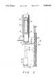
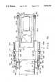
- FIG. 1is a longitudinal cross-sectional view of an overall vertical heat-treatment apparatus according to a embodiment of the present invention
- FIG. 2is a partial transversal cross-sectional view of the main part of the vertical heat-treatment apparatus of FIG. 1;
- FIG. 3is a plan view of wafer transfer device in the lower portion of the apparatus
- FIG. 4is a perspective view of a mechanism for carrying out the parallel transfer of carriers
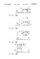
- FIGS. 5A to 5Dshow the movements of a carrier when the carrier on a stage is transferred to a carrier port by means of the mechanism for carrying out the parallel transfer of carriers;
- FIGS. 6A to 6Cshow the operation of a carrier posture change mechanism and a carrier receiving mechanism when the carrier is transferred from the carrier port to the lower portion of the apparatus;
- FIG. 7Ais a plan view of the carrier receiving mechanism when it does not holds a carrier
- FIG. 7Bis a plan view of the carrier receiving mechanism when it holds a carrier
- FIG. 8is a longitudinal cross-sectional view of a wafer loading/unloading mechanism
- FIG. 9is a transversal cross-sectional view of the wafer loading/unloading mechanism
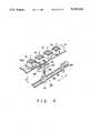
- FIG. 10is a perspective view of the forks of the wafer loading/unloading mechanism
- FIG. 11is a transversal cross-sectional view of the wafer loading/unloading mechanism
- FIGS. 12 and 13are plane views of an arm showing a rotation manner thereof and positioning members thereof;
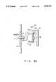
- FIG. 14is an elevation view showing the relation of a boat relative to the arm at those positions where wafers are transferred to and out of the boat and the boat is loaded and unloaded;
- FIG. 15is a perspective view showing a support system for holding the top of the boat.
- FIG. 16is a side view showing an engaging member and its components of the support system dismantled.
- a vertical heat-treatment apparatus 1is installed in an unmanned clean room and is fully automatically controlled by a computer system.
- the vertical heat-treatment apparatus 1comprises a process section 1a and a wafer transfer section 1b.
- the process section 1acomprises the upper portion of the apparatus 1
- the wafer transfer section 1bcomprises the lower portion of the apparatus 1.
- a fan 43 having a filter 44is provided between the process section 1a and the wafer transfer section 1b.
- the fan 43is disposed right above a carrier station 8 in the wafer transfer section 1b and supplies clean air to the station 8 when wafers W are transferred.
- the filter 44an HEPA filter or a ULPA filter is used.
- a carrier port 10, a process control section 150, a process gas supplying section 165 and an evacuating section 160are provided adjacent to the wafer transfer section 1b.
- the carrier port 10is provided on the front face of the wafer transfer section 1b and extends along a Y axis.
- a plurality of carriers 7are arranged at equal intervals on the carrier port 10.
- the movable base 30a of a carrier posture change mechanism 30is supported on the central portion of the port 10 by means of a horizontal support shaft 33.
- a parallel transfer mechanism 80(shown in FIG. 4) is mounted on the front face of the wafer transfer section 1b.
- the port 10is formed an opening so that the movable base 30a can be rotated about the shaft 33 between the horizontal state and the vertical state at the opening of the port 10.
- the upper end of the tube 2is closed and the lower end thereof is opened.
- the lower opening of the tube 2communicates with the wafer transfer section 1b.
- a lid member 15is disposed right under the lower opening of the process tube 2.
- a heat insulating cylindrical member 18on which a vertical quartz boat B is disposed.
- the lid member 15is carried by a support member 5, and nuts 5a of the support member 5 mesh with the ball screw 16a of a lift mechanism 16.
- the lid member 15has a larger diameter than the lower opening of the process tube 2.
- a process ga supplying tube(not shown) extends vertically along the inner peripheral wall of the tube 2 and is connected to a gas supplying source (not shown) via a mass-flow controller (not shown).
- An air exhaust tube 14extends from the lower portion of the tube 2 and is connected to the suction port of a vacuum pump (not shown). Between the process tube 2 and the coil heater 12 is disposed a heat equalizing tube 13 for rendering the temperature distribution in the tube uniform.
- the parallel transfer mechanism 8will now be explained with reference to FIG. 4.
- a truck (not shown) on which a robot runsis laid in front of the carrier port 10.
- the robot (not shown)transports carriers 7 to the port 10 and loads them thereon.
- the parallel transfer mechanism 80is provided on the front face of the carrier port 10 and has a ball screw 88 and a linear guide 87 extending along the Y axis so as to pass through a movable member 81.
- One end of the ball screw 88is connected to the driving shaft of a motor 89.
- the movable member 81contains a nut and a lift cylinder (neither shown), and the nut meshes with the ball screw 88.
- a chuck mechanism 84To the upper end portion of the cylinder rod 86 of the lift cylinder is fixed a chuck mechanism 84 which has a pair of arms 82 connected to the rod (not shown) of an air cylinder.
- the air cylinder for driving the arms 82is provided along the Y axis.
- the support shaft 33is connected to rotary drive mechanism (not shown) which has a lock mechanism for preventing rotation and a return mechanism.
- the driving system of the lock mechanism and the return mechanismis connected to that of the air cylinder 32 of clamps 31a and 31b via an automatic control circuit so as to cooperate therewith.
- the lock mechanismoperates to cause the movable base 30a to be held horizontally by the support shaft 30.
- the return mechanismoperates to cause the support shaft 33 to rotate reversely so that the movable base 30a returns to the horizontal state.
- a rotary roller 34is provided right under the movable base 30a.
- the roller 34is supported by a moving mechanism and is moved thereby so as to abut against the end faces of the wafer W exposed at the bottom of the carrier 7.
- the contact of the wafers W with the roller 34allows the orientation flats of the wafers W in the carrier 7 to align with each other.
- a wafer counter 35is provided at the vicinity of the roller 34.
- the wafer counter 35is also supported by the moving mechanism (not shown) and can be moved by it to a position close to a position right under the carriers 7.
- the wafer counter 35has emitting/receiving photo sensors 38 and counts the number of wafers by radiating the wafers W in the carrier 7 with light.
- the carrier transfer mechanism 11will be explained with reference to FIGS. 7A and 7B.
- the carrier transfer mechanism 11 and a wafer transfer mechanism 9are formed unitarily. This unitary assembly is supported by a rotary shaft 134 so as to be rotatable therearound as shown in FIG. 9 and to be lifted or lowered along the ball screw 16a in the directions along the Y axis as shown in FIG. 3.
- the carrier transfer mechanism 11has a pair of links 37a and 37b opposed to each other. They are in a mirror image relationship. Thus, only one link 37a is explained for convenience.
- a main member 48ais fixed to a side portion of the front face of a main body frame 47.
- a fixed arm 49ais attached to the front end of the main body 48a, and a cylinder 50a is fixed to a lateral wall of the main member 48a.
- the cylinder 50adrives a movable arm comprising a short arm 52a, a long arm 53a, a first pawl member 54a, a second pawl member 55a and pins 56, and extending along the fixed arm 49a at its outside.
- One end of the short arm 52ais connected to the forward end of the rod 51a of the cylinder 50a by means of a pin 56
- one end of the long arm 43ais connected to the other end of the short arm 52a by means of another pin 56.
- the first pawl member 54ais connected to the forward end of the long arm 53a by means of a further pin 56
- the second pawl member 55ais connected to the long arm 53a at the vicinity of its rear end by means of a still further pin 56.
- the other ends of the first and second pawl members 54a and 55aare connected to the appropriate portions of the fixed arm 49a by means of other pins 56.
- the forward ends of the first and second pawl members 54a and 55aare rotated so that they are directed towards the direction perpendicular to the lengthwise direction of the fixed arm 49a.
- the carrier 7is formed with a depression 7a and a stop 7b at its side wall. The relative position between the carrier 7 and the carrier transfer mechanism 11 is adjusted by matching first pawl member 54a and the second pawl member 55a to the depression 7a and the stop 7b, respectively.
- Two kinds of forksconsisting of a set of five forks 70a to 70e and a fork 70f and made of aluminum alloy are provided on the frame 47 of the wafer transfer mechanism 9 and are supported by support members 60 and 62, respectively, so that they are driven separately by means of belt driving mechanisms 121 and 128, respectively.
- the forks 70a to 70fmay be made of alumina, SiC or quartz instead of aluminum alloy.
- the driving mechanism 121 for the set of five forks 70a to 70ecomprises a timing belt 123 stretched between a pair of pulleys 124, a motor 122 connected to one of the pulleys 124 and an idler wheel 125.
- the other belt driving mechanism 128has the similar structure to the belt driving mechanism 121.
- the frame 131 of the swivel mechanism 130is mounted on the bottom of the frame 45 via bearings 135.
- a step motoris used as a motor 133 of the swivel mechanism 130 and the rotation of the shaft 13 of the motor 133 is automatically controlled by the computer system.
- the carrier transfer mechanism 11is moved by an X axis driving mechanism 141 of a belt driving type in the directions of the X axis.
- the motor 142 of the X axis driving mechanism 141is fixed to the frame 47, and a motor driving shaft 143 is connected to pulleys 144 and 145.
- the set of five forks 70a to 70e of the wafer transfer mechanism 9are placed between a base 73 and a plate 71 and fixed by screws 72 so as to be arranged at equal intervals.
- a ball 79is placed in depressions 78a and 78b formed in the opposed faces of the support member 60 and the base 73, and the position of the base 73 as well as the positions of the forks 70a to 70e can be changed by means of first and second adjustment screws 76 and 77.
- the horizontal and vertical positions of the tips of the forks 70a to 70eare adjusted by means of the four first adjustment screws 76, and the rotational position of the tips of the forks 70a to 70e is adjusted by means of the four second adjustment screws 77.
- Fixing screws 75fix the base 73 to the support member 60.
- a boat transfer mechanism 6will be described in detail with reference to FIGS. 12 and 13.
- the boat transfer mechanism 6includes rotary shaft member 20, an arm 19 supported by the rotary shaft member 20 and a support portion 21 formed at the front end of the arm 19 and shaped like a semi-circle.
- the rotary shaft member 20rotates the arm 19 through rotating system and moves it up and down through a lift system.
- the arm 19is rotated from a home position H which is adjacent to a boat waiting system 90 to a wafer transfer position R where wafers are received from the wafer transfer mechanism 9, and vice versa by means of the rotating system of the rotary shaft member 20.
- the wafer transfer position Ris on a straight line passing through the center of the cassettes carried to the I/0 stage, the center Q of rotation of the wafer transfer apparatus and the axial center of the reaction tube 2.
- the center of the boat B at the wafer transfer position Rmust be positioned at the center of the moving direction of the wafer transfer forks 70a-70e.
- Three chips 21a made of quartz and intended to contact the side of the boat Bare arranged along the U-shaped recess 22 of the support portion 21 for this purpose.
- the chips 21acontact the side of the lower cylindrical portion b1 of the boat B received in the U-shaped recess 22 of the support portion 21 (see FIG. 14) to align the center of the boat B with the center of the support portion 21.
- the direction of wafer carrying groove b2 of the boat B at the wafer transfer position Rmust be then positioned to align with the moving direction of the wafer transfer forks 70a-70e.
- the support portion 21is provided with plural or two positioning pins 21b for this purpose.
- the pins 21b at the home position Hfor example, contact the flat peripheral portion of a lower flange b3 of the boat B received in the U-shaped recess 22 of the support portion 21 (see FIG. 14) to determine the direction of the wafer housing groove b2 of the boat B. This direction is aligned with the moving direction of the wafer transfer forks 70a-70e when the boat B is carried to the wafer transfer position R.
- Positioningmust be further carried out not to tilt the wafer carrying grooves b2 of the boat B at the wafer transfer position R relative to wafer support planes of the wafer transfer forks 70a-70e.
- Three chips 21c made of quartzare arranged for this purpose along the U-shaped recess 22 of the support at a same interval to support the underside of the lower flange b3 of the boat B (see FIG. 14).
- the chips 21care provided with adjuster systems to adjust the verticality of the boat B.
- Each of the chips 21cis provided with a screw hole passing through the support portion 21.
- a screwis screwed into the screw hole and the chip 21c made of quartz is fixed to the top of the screw. When the screws are turned, therefore, the verticality of the boat B can be adjusted.
- the boat waiting system 90is located adjacent to the home position H of the arm 19, as shown in FIG. 3.
- the boat waiting system 90is provided with a table 92 which receives the lower portion of the boat B to hold it vertical and which can be moved along a track 94 by a drive system (not shown).
- another table 24 which receives the lower portion of the boat B to hold it verticalis located at the wafer transfer position R. This table 24 can be moved up and down.
- support system 26which holds the top of the boat B at the wafer transfer time, as shown in FIG. 14.
- the support system 26includes an engaging member 27 made of quartz and shaped like a truncate cone. This engaging member 27 is moved up and down by a system which will be described below and engaged with a hole or recess of a ring-shaped projection b4 on the top of the boat B.
- the engaging member 27 made of quartz and shaped like a truncate conecomprises flange 271 and a truncate cone portion 272 made integral to each other.
- a counter bore 273 and a screw hole 274are formed passing through these flange 271 and truncate cone portion 272 along their axial center.
- the screw hole 274is aligned with a screw hole 269 formed in the lower end of the shaft 265.
- a metal screw 275is screwed into the screw holes 274 and 269 and the engaging member 27 is thus fixed to the flange 268 at the lower end of the shaft 265.
- the head of the screw 275is completely embedded this time in the bore 273 to thereby contact only the quartz portion of the engaging member 27 with the projection b4 of the boat B.
- the carriers 7are successively mounted on the boat 10 by the robot. Wafer transferring and heat-treating requisites are inputted to the CPU of the computer system by the keyboard. There are carried 25 sheets of the semiconductor wafers W at maximum in the carrier 7.
- Command signalis sent from the CPU to the parallel transfer mechanism 80 and the mechanism 80 is thus rendered operative.
- the carrier 7is grasped by the paired arm 82 of the parallel transfer mechanism 80 and mounted on the movable base 30a.
- the carrier 7is held by the arms 31a and 31b of the carrier posture change mechanism 30. Since the arm 31a has a stronger locking force than the arm 31b, the arm 31a is set in position with respect to the carrier 7 before the arm 31b is set. Then, the roller 34 is caused to contact the wafers W in the carrier 7 to align the orientation flats of wafers. Next, the number of the wafers W in the carrier 7 is counted by the wafer counter 35. After unlocking, the shaft 33 is rotated counterclockwise to rotate the carrier 7 as well as movable base 30a through 90 degrees. As shown in FIG. 6B, the wafers W in the carrier 7 take a horizontal position.
- the carrier transfer mechanism 11is advanced towards the carrier 7, and the links 37a and 37b are positioned at the sides of the carrier 7. Thereafter, the rods 51a and 51b are projected from the cylinders 50a and 50b. The tips of the second pawl members 55a and 55b contact the stops 7b of the carrier 7 and the carrier transfer mechanisms 11 and the carrier 7 are set in position. As shown in FIG. 7B, the tips of the first pawl members 54a and 54b are fitted in the depressions 7a of the carrier 7, whereby the carrier 7 is held by the links 37a and 37b.
- the carrier station 8has four stories, each of which has two compartments. Each compartment of the carrier station 8 is provided with a sensor (not shown) for detecting the carrier 7. The compartments of the carrier station 8 in which the carriers 7 are received are previously programmed. While the wafers W are not transferred from carriers to the boat B, the carriers on the port 10 are transferred to the carrier station 8 in succession.
- the boat Benters the wafer transfer section 1b through an inlet (not shown) and is set at a predetermined waiting position.
- the carrier transfer mechanism 11 and the wafer transfer mechanism 9are replaced from each other, and the forks 70a to 70e are caused to face the openings of the carrier 7.
- the forks 70a to 70eare advanced, and, after the tips of the forks have been inserted in the carrier 7, the forks 70a to 70e stop at predetermined position.
- the forks 70a to 70eare raised a little and pick up five wafers W in the carrier 7.
- the forks 70a to 70eare retracted and rotated to face the boat B.
- the forks 70a to 70bare advanced again to insert the wafers W in the boat B and are lowered. By doing so, the five wafers W are transferred from the forks 70a to 70e to the boat 8.
- the boat Bis held vertical on the table 24 which is located at the wafer transfer position R.
- the table 24is lifted or the engaging member 27 is lowered, the engaging member 27 is engaged with the hole in the projection b4 on the top of the boat B and the top of the boat B is thus fixedly held.
- the wafers Ware transferred into the boat B while holding the boat B under this state.
- the table 24is lowered or the engaging member 27 is lifted and the boat B is thus released from its fixed state.
- the arm 19 of the boat transfer system 9is swung to hold the lower portion of the boat B. As shown in FIG. 14, the arm 19 is lifted or the table 24 is lowered to release the boat B from the table 24.
- the arm 19is then swung to carry the boat B onto the table 92 of the boat waiting system 90.
- the arm 19is lowered and the boat B is thus mounted on the table 92.
- the table 92is moved along the track 94 and the boat B is thus released from the arm 19.
- Another boat B which is different from the above-mentioned one and to which heat treatment has been applied in the reaction tube 2is lowered by the lift system 16.
- the arm 19is swung to hold the lower portion of the boat B disposed on the heat insulating cylindrical member 18 on the support member of the lift system 16.
- the arm 19is lifted or the support member 5 is lowered and the boat B is thus transferred from the heat insulating cylindrical member 18 to the arm 19.
- the boat Bis carried to the wafer transfer position R by the swinging arm 19 and mounted o the table 24 as described above.
- the wafers which have been heat-treatedare transferred from the boat B to the carriers 7 on the carrier stations 8 by the transfer system 9 in a process reverse to the above-described one intended to transfer the wafers from the carriers to the boat B.
- the arm 19While the heat-treated wafers are being transferred from the boat B to the carriers 7, the arm 19 is swung to the home position H or above the boat waiting system 90.
- the waiting boat B on which not-treated wafers W have been mountedis carried by the table 92.
- the lower portion of this boat Bis fitted into the support portion 21 of the arm 19 which is located at the home position H.
- the arm 19is lifted and the boat B is thus released from the table 92.
- the arm 19is then swung to carry the boat B on which the not-treated wafers have been mounted to the axial center of the reaction tube 2 or onto the support member 5 of the lift system 16.
- the arm 19is lowered or the support member 5 is lifted while keeping the axial center of the boat B aligned with that of the heat insulating cylindrical member 18 and the boat B is thus transferred onto the heat insulating cylindrical member 18.
- the arm 19is then retreated to the home position H.
- the support member 5 of the lift system 16lifts until the lid member 15 closes the reaction tube 2, and the boat B is thus held or loaded in the reaction tube 2.
- the heat treatmentis then carried out, controlling the temperature in the reaction tube 2 by the heater 12 and introducing treatment gas into the reaction tube 2.
Landscapes
- Engineering & Computer Science (AREA)
- Physics & Mathematics (AREA)
- Condensed Matter Physics & Semiconductors (AREA)
- General Physics & Mathematics (AREA)
- Manufacturing & Machinery (AREA)
- Computer Hardware Design (AREA)
- Microelectronics & Electronic Packaging (AREA)
- Power Engineering (AREA)
- Health & Medical Sciences (AREA)
- Toxicology (AREA)
- Container, Conveyance, Adherence, Positioning, Of Wafer (AREA)
Abstract
Description
Claims (17)
Applications Claiming Priority (2)
| Application Number | Priority Date | Filing Date | Title |
|---|---|---|---|
| JP1-209220 | 1989-08-11 | ||
| JP20922089AJP2905857B2 (en) | 1989-08-11 | 1989-08-11 | Vertical processing equipment |
Publications (1)
| Publication Number | Publication Date |
|---|---|
| US5048164Atrue US5048164A (en) | 1991-09-17 |
Family
ID=16569337
Family Applications (1)
| Application Number | Title | Priority Date | Filing Date |
|---|---|---|---|
| US07/564,318Expired - LifetimeUS5048164A (en) | 1989-08-11 | 1990-08-08 | Vertical heat-treatment apparatus having boat transfer mechanism |
Country Status (3)
| Country | Link |
|---|---|
| US (1) | US5048164A (en) |
| JP (1) | JP2905857B2 (en) |
| KR (1) | KR0139029B1 (en) |
Cited By (53)
| Publication number | Priority date | Publication date | Assignee | Title |
|---|---|---|---|---|
| US5162047A (en)* | 1989-08-28 | 1992-11-10 | Tokyo Electron Sagami Limited | Vertical heat treatment apparatus having wafer transfer mechanism and method for transferring wafers |
| US5178639A (en)* | 1990-06-28 | 1993-01-12 | Tokyo Electron Sagami Limited | Vertical heat-treating apparatus |
| US5180273A (en)* | 1989-10-09 | 1993-01-19 | Kabushiki Kaisha Toshiba | Apparatus for transferring semiconductor wafers |
| US5324331A (en)* | 1989-12-21 | 1994-06-28 | Florian Fischer | Transport system, in particular for transporting silicon monocrystals through the tank of a research reactor |
| US5430271A (en)* | 1990-06-12 | 1995-07-04 | Dainippon Screen Mfg. Co., Ltd. | Method of heat treating a substrate with standby and treatment time periods |
| US5443348A (en)* | 1993-07-16 | 1995-08-22 | Semiconductor Systems, Inc. | Cassette input/output unit for semiconductor processing system |
| US5445484A (en)* | 1990-11-26 | 1995-08-29 | Hitachi, Ltd. | Vacuum processing system |
| US5468112A (en)* | 1992-10-05 | 1995-11-21 | Tokyo Electron Limited | Wafer container and wafer aligning apparatus |
| US5516251A (en)* | 1993-08-12 | 1996-05-14 | Kabushiki Kaisha Shinkawa | Magazine carrying apparatus |
| US5525024A (en)* | 1994-08-17 | 1996-06-11 | Applied Materials, Inc. | Cassette loader having compound translational motion |
| US5540098A (en)* | 1993-02-16 | 1996-07-30 | Tokyo Electron Limited | Transfer device |
| US5562383A (en)* | 1993-04-13 | 1996-10-08 | Tokyo Electron Kabushiki Kaisha | Treatment apparatus |
| US5562387A (en)* | 1993-10-04 | 1996-10-08 | Tokyo Electron Limited | Device for transferring plate-like objects |
| WO1997005527A1 (en)* | 1995-07-27 | 1997-02-13 | Semiconductor Systems, Inc. | Method and apparatus for curing photoresist |
| US5651823A (en)* | 1993-07-16 | 1997-07-29 | Semiconductor Systems, Inc. | Clustered photolithography system |
| US5697749A (en)* | 1992-07-17 | 1997-12-16 | Tokyo Electron Kabushiki Kaisha | Wafer processing apparatus |
| US5709519A (en)* | 1992-01-22 | 1998-01-20 | Tokyo Ohka Kogyo Co., Ltd. | Plasma processing apparatus |
| US5718552A (en)* | 1993-03-22 | 1998-02-17 | Gruetzediek; Hartmut | Procedure and facility for handling and transport of wafers in ultra-clean rooms |
| US5957648A (en)* | 1996-12-11 | 1999-09-28 | Applied Materials, Inc. | Factory automation apparatus and method for handling, moving and storing semiconductor wafer carriers |
| US5964561A (en)* | 1996-12-11 | 1999-10-12 | Applied Materials, Inc. | Compact apparatus and method for storing and loading semiconductor wafer carriers |
| US5971696A (en)* | 1996-10-01 | 1999-10-26 | Tokyo Electron Limited | System for carrying-in of cassette for substrates to be processed |
| US6332744B1 (en)* | 1999-07-26 | 2001-12-25 | Murata Kakai Kabushiki Kaisha | Automatic warehouse and transfer system using the same |
| US6439822B1 (en)* | 1998-09-22 | 2002-08-27 | Tokyo Electron Limited | Substrate processing apparatus and substrate processing method |
| US6540466B2 (en) | 1996-12-11 | 2003-04-01 | Applied Materials, Inc. | Compact apparatus and method for storing and loading semiconductor wafer carriers |
| US20030209404A1 (en)* | 2000-07-07 | 2003-11-13 | Davis Jeffry A. | Automated processing system |
| US6709522B1 (en)* | 2000-07-11 | 2004-03-23 | Nordson Corporation | Material handling system and methods for a multichamber plasma treatment system |
| WO2004021411A3 (en)* | 2002-08-31 | 2004-04-15 | Applied Materials Inc | Method and apparatus for supplying substrates to a processing tool |
| US6723174B2 (en) | 1996-03-26 | 2004-04-20 | Semitool, Inc. | Automated semiconductor processing system |
| US20040076496A1 (en)* | 2002-08-31 | 2004-04-22 | Applied Materials, Inc. | Methods and apparatus for using substrate carrier movement to actuate substrate carrier door opening/closing |
| US20040191030A1 (en)* | 2003-01-27 | 2004-09-30 | Applied Materials, Inc. | Methods and apparatus for transporting substrate carriers |
| US20050095110A1 (en)* | 2002-08-31 | 2005-05-05 | Lowrance Robert B. | Method and apparatus for unloading substrate carriers from substrate carrier transport system |
| US6942738B1 (en)* | 1996-07-15 | 2005-09-13 | Semitool, Inc. | Automated semiconductor processing system |
| US6955197B2 (en) | 2002-08-31 | 2005-10-18 | Applied Materials, Inc. | Substrate carrier having door latching and substrate clamping mechanisms |
| US20050273191A1 (en)* | 2003-01-27 | 2005-12-08 | Englhardt Eric A | Small lot size lithography bays |
| US20070059861A1 (en)* | 2003-01-27 | 2007-03-15 | Applied Materials, Inc. | Systems and methods for transferring small lot size substrate carriers between processing tools |
| US7234584B2 (en) | 2002-08-31 | 2007-06-26 | Applied Materials, Inc. | System for transporting substrate carriers |
| US7243003B2 (en) | 2002-08-31 | 2007-07-10 | Applied Materials, Inc. | Substrate carrier handler that unloads substrate carriers directly from a moving conveyor |
| US20080069672A1 (en)* | 2006-09-13 | 2008-03-20 | Daifuku Co., Ltd. | Substrate storage facility and substrate processing facility, and method for operating substrate storage |
| US20080089765A1 (en)* | 2006-09-13 | 2008-04-17 | Daifuku Co., Ltd. | Method for processing substrates |
| US20080193888A1 (en)* | 2007-02-14 | 2008-08-14 | Tokyo Electron Limited | Vertical type heat processing apparatus and vertical type heat processing method |
| US20080199818A1 (en)* | 2007-01-30 | 2008-08-21 | Tokyo Electron Limited | Vertical heat processing apparatus and heat processing method using the vertical heat processing apparatus |
| US20080306623A1 (en)* | 2007-06-07 | 2008-12-11 | United Microelectronics Corp. | Method for automatically checking sequence of loading boats and batches for semiconductor manufacturing process |
| US7506746B2 (en) | 2002-08-31 | 2009-03-24 | Applied Materials, Inc. | System for transporting substrate carriers |
| US7578647B2 (en) | 2003-01-27 | 2009-08-25 | Applied Materials, Inc. | Load port configurations for small lot size substrate carriers |
| US7594789B2 (en) | 2003-01-27 | 2009-09-29 | Applied Materials, Inc. | Overhead transfer flange and support for suspending a substrate carrier |
| US7684895B2 (en) | 2002-08-31 | 2010-03-23 | Applied Materials, Inc. | Wafer loading station that automatically retracts from a moving conveyor in response to an unscheduled event |
| US7857570B2 (en) | 2003-08-28 | 2010-12-28 | Applied Materials, Inc. | Method and apparatus for supplying substrates to a processing tool |
| US7930061B2 (en) | 2002-08-31 | 2011-04-19 | Applied Materials, Inc. | Methods and apparatus for loading and unloading substrate carriers on moving conveyors using feedback |
| US20110162633A1 (en)* | 2007-09-26 | 2011-07-07 | Tokyo Electron Limited | Heat treatment method and heat treatment apparatus |
| US8672121B2 (en) | 2007-10-22 | 2014-03-18 | Applied Materials, Inc. | Methods and apparatus for transporting substrate carriers |
| NL2014606A (en)* | 2015-04-09 | 2016-10-12 | Tempress Ip B V | Wafer boat loader assembly, furnace system, use thereof and method for operating said assembly. |
| US11309168B2 (en)* | 2017-02-16 | 2022-04-19 | Tokyo Electron Limited | Vacuum processing apparatus and maintenance apparatus |
| US20230420280A1 (en)* | 2022-06-22 | 2023-12-28 | SCREEN Holdings Co., Ltd. | Substrate treating apparatus |
Families Citing this family (1)
| Publication number | Priority date | Publication date | Assignee | Title |
|---|---|---|---|---|
| KR100819098B1 (en)* | 2007-04-16 | 2008-04-03 | 삼성전자주식회사 | Vertical furnace semiconductor manufacturing facility with lot unit transportation processing function and its transportation processing method |
Citations (9)
| Publication number | Priority date | Publication date | Assignee | Title |
|---|---|---|---|---|
| US4244673A (en)* | 1979-02-16 | 1981-01-13 | Emerson Plastronics | Consecutive wafer transfer apparatus and method |
| US4568234A (en)* | 1983-05-23 | 1986-02-04 | Asq Boats, Inc. | Wafer transfer apparatus |
| US4611966A (en)* | 1984-05-30 | 1986-09-16 | Johnson Lester R | Apparatus for transferring semiconductor wafers |
| EP0209660A2 (en)* | 1985-07-24 | 1987-01-28 | Hewlett-Packard Company | Apparatus and method for automated cassette handling |
| US4699556A (en)* | 1984-05-17 | 1987-10-13 | Proconics International, Inc. | Object handling apparatus |
| US4750857A (en)* | 1986-05-05 | 1988-06-14 | The Perkin-Elmer Corporation | Wafer cassette transfer mechanism |
| US4806057A (en)* | 1986-04-22 | 1989-02-21 | Motion Manufacturing, Inc. | Automatic wafer loading method and apparatus |
| US4938655A (en)* | 1988-02-25 | 1990-07-03 | Tel Sagami Limited | Wafer transfer method |
| US4938691A (en)* | 1987-11-17 | 1990-07-03 | Tel Sagami Limited | Heat-treating apparatus |
Family Cites Families (11)
| Publication number | Priority date | Publication date | Assignee | Title |
|---|---|---|---|---|
| JPS5875840A (en)* | 1981-10-30 | 1983-05-07 | Fujitsu Ltd | Heat treatment furnace for semiconductors |
| JPS6021538A (en)* | 1983-07-18 | 1985-02-02 | Toshiba Ceramics Co Ltd | Carrier jig for semiconductor auto-loading |
| JPH07105356B2 (en)* | 1985-03-13 | 1995-11-13 | 株式会社東芝 | Vertical diffusion furnace device |
| JPS61221368A (en)* | 1985-03-27 | 1986-10-01 | Kyocera Corp | Mass production method for amorphous silicon film |
| JPS61291335A (en)* | 1985-06-19 | 1986-12-22 | Denkoo:Kk | Semiconductor transfer device |
| JPS6291439U (en)* | 1985-11-27 | 1987-06-11 | ||
| JPS6294626U (en)* | 1985-12-02 | 1987-06-17 | ||
| JP2656020B2 (en)* | 1986-01-14 | 1997-09-24 | キヤノン株式会社 | Deposition film forming equipment |
| JPS62222632A (en)* | 1986-03-24 | 1987-09-30 | Nec Corp | Vertical type vapor growth equipment |
| JPS63140523A (en)* | 1986-12-03 | 1988-06-13 | Hitachi Ltd | processing equipment |
| JPH0195730U (en)* | 1987-12-18 | 1989-06-26 |
- 1989
- 1989-08-11JPJP20922089Apatent/JP2905857B2/ennot_activeExpired - Lifetime
- 1990
- 1990-08-08USUS07/564,318patent/US5048164A/ennot_activeExpired - Lifetime
- 1990-08-11KRKR1019900012375Apatent/KR0139029B1/ennot_activeExpired - Fee Related
Patent Citations (9)
| Publication number | Priority date | Publication date | Assignee | Title |
|---|---|---|---|---|
| US4244673A (en)* | 1979-02-16 | 1981-01-13 | Emerson Plastronics | Consecutive wafer transfer apparatus and method |
| US4568234A (en)* | 1983-05-23 | 1986-02-04 | Asq Boats, Inc. | Wafer transfer apparatus |
| US4699556A (en)* | 1984-05-17 | 1987-10-13 | Proconics International, Inc. | Object handling apparatus |
| US4611966A (en)* | 1984-05-30 | 1986-09-16 | Johnson Lester R | Apparatus for transferring semiconductor wafers |
| EP0209660A2 (en)* | 1985-07-24 | 1987-01-28 | Hewlett-Packard Company | Apparatus and method for automated cassette handling |
| US4806057A (en)* | 1986-04-22 | 1989-02-21 | Motion Manufacturing, Inc. | Automatic wafer loading method and apparatus |
| US4750857A (en)* | 1986-05-05 | 1988-06-14 | The Perkin-Elmer Corporation | Wafer cassette transfer mechanism |
| US4938691A (en)* | 1987-11-17 | 1990-07-03 | Tel Sagami Limited | Heat-treating apparatus |
| US4938655A (en)* | 1988-02-25 | 1990-07-03 | Tel Sagami Limited | Wafer transfer method |
Cited By (87)
| Publication number | Priority date | Publication date | Assignee | Title |
|---|---|---|---|---|
| US5162047A (en)* | 1989-08-28 | 1992-11-10 | Tokyo Electron Sagami Limited | Vertical heat treatment apparatus having wafer transfer mechanism and method for transferring wafers |
| US5180273A (en)* | 1989-10-09 | 1993-01-19 | Kabushiki Kaisha Toshiba | Apparatus for transferring semiconductor wafers |
| US5324331A (en)* | 1989-12-21 | 1994-06-28 | Florian Fischer | Transport system, in particular for transporting silicon monocrystals through the tank of a research reactor |
| US5430271A (en)* | 1990-06-12 | 1995-07-04 | Dainippon Screen Mfg. Co., Ltd. | Method of heat treating a substrate with standby and treatment time periods |
| US5178639A (en)* | 1990-06-28 | 1993-01-12 | Tokyo Electron Sagami Limited | Vertical heat-treating apparatus |
| US5445484A (en)* | 1990-11-26 | 1995-08-29 | Hitachi, Ltd. | Vacuum processing system |
| US5709519A (en)* | 1992-01-22 | 1998-01-20 | Tokyo Ohka Kogyo Co., Ltd. | Plasma processing apparatus |
| US5697749A (en)* | 1992-07-17 | 1997-12-16 | Tokyo Electron Kabushiki Kaisha | Wafer processing apparatus |
| US5468112A (en)* | 1992-10-05 | 1995-11-21 | Tokyo Electron Limited | Wafer container and wafer aligning apparatus |
| US5540098A (en)* | 1993-02-16 | 1996-07-30 | Tokyo Electron Limited | Transfer device |
| US5779425A (en)* | 1993-03-22 | 1998-07-14 | Gruetzediek; Hartmut | Procedure and facility for handling and transport of wafers in ultra-clean rooms |
| US5718552A (en)* | 1993-03-22 | 1998-02-17 | Gruetzediek; Hartmut | Procedure and facility for handling and transport of wafers in ultra-clean rooms |
| US5562383A (en)* | 1993-04-13 | 1996-10-08 | Tokyo Electron Kabushiki Kaisha | Treatment apparatus |
| US5829939A (en)* | 1993-04-13 | 1998-11-03 | Tokyo Electron Kabushiki Kaisha | Treatment apparatus |
| US5766824A (en)* | 1993-07-16 | 1998-06-16 | Semiconductor Systems, Inc. | Method and apparatus for curing photoresist |
| US5651823A (en)* | 1993-07-16 | 1997-07-29 | Semiconductor Systems, Inc. | Clustered photolithography system |
| US5443348A (en)* | 1993-07-16 | 1995-08-22 | Semiconductor Systems, Inc. | Cassette input/output unit for semiconductor processing system |
| US5516251A (en)* | 1993-08-12 | 1996-05-14 | Kabushiki Kaisha Shinkawa | Magazine carrying apparatus |
| US5562387A (en)* | 1993-10-04 | 1996-10-08 | Tokyo Electron Limited | Device for transferring plate-like objects |
| US5525024A (en)* | 1994-08-17 | 1996-06-11 | Applied Materials, Inc. | Cassette loader having compound translational motion |
| WO1997005527A1 (en)* | 1995-07-27 | 1997-02-13 | Semiconductor Systems, Inc. | Method and apparatus for curing photoresist |
| US6723174B2 (en) | 1996-03-26 | 2004-04-20 | Semitool, Inc. | Automated semiconductor processing system |
| US6942738B1 (en)* | 1996-07-15 | 2005-09-13 | Semitool, Inc. | Automated semiconductor processing system |
| US5971696A (en)* | 1996-10-01 | 1999-10-26 | Tokyo Electron Limited | System for carrying-in of cassette for substrates to be processed |
| US5957648A (en)* | 1996-12-11 | 1999-09-28 | Applied Materials, Inc. | Factory automation apparatus and method for handling, moving and storing semiconductor wafer carriers |
| US5964561A (en)* | 1996-12-11 | 1999-10-12 | Applied Materials, Inc. | Compact apparatus and method for storing and loading semiconductor wafer carriers |
| US6540466B2 (en) | 1996-12-11 | 2003-04-01 | Applied Materials, Inc. | Compact apparatus and method for storing and loading semiconductor wafer carriers |
| US20070243048A1 (en)* | 1996-12-11 | 2007-10-18 | Applied Materials, Inc. | Compact apparatus and method for storing and loading semiconductor wafer carriers |
| US7682123B2 (en) | 1996-12-11 | 2010-03-23 | Applied Materials, Inc. | Compact apparatus and method for storing and loading semiconductor wafer carriers |
| US20100042253A1 (en)* | 1996-12-11 | 2010-02-18 | Applied Materials, Inc. | Wafer carrier handling methods, systems and apparatus for semiconductor wafer fabrication |
| US6746197B2 (en) | 1998-09-22 | 2004-06-08 | Tokyo Electron Limited | Substrate processing apparatus and substrate processing method |
| US6439822B1 (en)* | 1998-09-22 | 2002-08-27 | Tokyo Electron Limited | Substrate processing apparatus and substrate processing method |
| US6332744B1 (en)* | 1999-07-26 | 2001-12-25 | Murata Kakai Kabushiki Kaisha | Automatic warehouse and transfer system using the same |
| US7278813B2 (en) | 2000-07-07 | 2007-10-09 | Semitool, Inc. | Automated processing system |
| US20030209404A1 (en)* | 2000-07-07 | 2003-11-13 | Davis Jeffry A. | Automated processing system |
| US6709522B1 (en)* | 2000-07-11 | 2004-03-23 | Nordson Corporation | Material handling system and methods for a multichamber plasma treatment system |
| US7243003B2 (en) | 2002-08-31 | 2007-07-10 | Applied Materials, Inc. | Substrate carrier handler that unloads substrate carriers directly from a moving conveyor |
| US7506746B2 (en) | 2002-08-31 | 2009-03-24 | Applied Materials, Inc. | System for transporting substrate carriers |
| US20060072992A1 (en)* | 2002-08-31 | 2006-04-06 | Applied Materials, Inc. | Substrate carrier having door latching and substrate clamping mechanisms |
| US7930061B2 (en) | 2002-08-31 | 2011-04-19 | Applied Materials, Inc. | Methods and apparatus for loading and unloading substrate carriers on moving conveyors using feedback |
| US7792608B2 (en) | 2002-08-31 | 2010-09-07 | Applied Materials, Inc. | Substrate carrier handler that unloads substrate carriers directly from a moving conveyor |
| US7684895B2 (en) | 2002-08-31 | 2010-03-23 | Applied Materials, Inc. | Wafer loading station that automatically retracts from a moving conveyor in response to an unscheduled event |
| US7234584B2 (en) | 2002-08-31 | 2007-06-26 | Applied Materials, Inc. | System for transporting substrate carriers |
| US6955197B2 (en) | 2002-08-31 | 2005-10-18 | Applied Materials, Inc. | Substrate carrier having door latching and substrate clamping mechanisms |
| US7258520B2 (en) | 2002-08-31 | 2007-08-21 | Applied Materials, Inc. | Methods and apparatus for using substrate carrier movement to actuate substrate carrier door opening/closing |
| US20050095110A1 (en)* | 2002-08-31 | 2005-05-05 | Lowrance Robert B. | Method and apparatus for unloading substrate carriers from substrate carrier transport system |
| WO2004021411A3 (en)* | 2002-08-31 | 2004-04-15 | Applied Materials Inc | Method and apparatus for supplying substrates to a processing tool |
| US7673735B2 (en) | 2002-08-31 | 2010-03-09 | Applied Materials, Inc. | System for transporting substrate carriers |
| US7299831B2 (en) | 2002-08-31 | 2007-11-27 | Applied Materials, Inc. | Substrate carrier having door latching and substrate clamping mechanisms |
| US7346431B2 (en) | 2002-08-31 | 2008-03-18 | Applied Materials, Inc. | Substrate carrier handler that unloads substrate carriers directly from a moving conveyer |
| US20040076496A1 (en)* | 2002-08-31 | 2004-04-22 | Applied Materials, Inc. | Methods and apparatus for using substrate carrier movement to actuate substrate carrier door opening/closing |
| US7359767B2 (en) | 2002-08-31 | 2008-04-15 | Applied Materials, Inc. | Substrate carrier handler that unloads substrate carriers directly from a moving conveyor |
| US7527141B2 (en) | 2002-08-31 | 2009-05-05 | Applied Materials, Inc. | System for transporting substrate carriers |
| US7578647B2 (en) | 2003-01-27 | 2009-08-25 | Applied Materials, Inc. | Load port configurations for small lot size substrate carriers |
| US7778721B2 (en) | 2003-01-27 | 2010-08-17 | Applied Materials, Inc. | Small lot size lithography bays |
| US7077264B2 (en) | 2003-01-27 | 2006-07-18 | Applied Material, Inc. | Methods and apparatus for transporting substrate carriers |
| US20070059861A1 (en)* | 2003-01-27 | 2007-03-15 | Applied Materials, Inc. | Systems and methods for transferring small lot size substrate carriers between processing tools |
| US7367446B2 (en) | 2003-01-27 | 2008-05-06 | Applied Materials, Inc. | Methods and apparatus for transporting substrate carriers |
| US7506752B2 (en) | 2003-01-27 | 2009-03-24 | Applied Materials, Inc. | Methods and apparatus for transporting substrate carriers |
| US7711445B2 (en) | 2003-01-27 | 2010-05-04 | Applied Materials, Inc. | Systems and methods for transferring small lot size substrate carriers between processing tools |
| US7537108B2 (en) | 2003-01-27 | 2009-05-26 | Applied Materials, Inc. | Methods and apparatus for transporting substrate carriers |
| US20050273191A1 (en)* | 2003-01-27 | 2005-12-08 | Englhardt Eric A | Small lot size lithography bays |
| US7594789B2 (en) | 2003-01-27 | 2009-09-29 | Applied Materials, Inc. | Overhead transfer flange and support for suspending a substrate carrier |
| US7611318B2 (en) | 2003-01-27 | 2009-11-03 | Applied Materials, Inc. | Overhead transfer flange and support for suspending a substrate carrier |
| US7221993B2 (en) | 2003-01-27 | 2007-05-22 | Applied Materials, Inc. | Systems and methods for transferring small lot size substrate carriers between processing tools |
| US20040191030A1 (en)* | 2003-01-27 | 2004-09-30 | Applied Materials, Inc. | Methods and apparatus for transporting substrate carriers |
| US7293642B2 (en) | 2003-01-27 | 2007-11-13 | Applied Materials, Inc. | Methods and apparatus for transporting substrate carriers |
| US7857570B2 (en) | 2003-08-28 | 2010-12-28 | Applied Materials, Inc. | Method and apparatus for supplying substrates to a processing tool |
| US8118530B2 (en)* | 2006-09-13 | 2012-02-21 | Daifuku Co., Ltd. | Substrate storage facility and substrate processing facility, and method for operating substrate storage |
| US20080089765A1 (en)* | 2006-09-13 | 2008-04-17 | Daifuku Co., Ltd. | Method for processing substrates |
| US7955044B2 (en)* | 2006-09-13 | 2011-06-07 | Daifuku Co., Ltd. | Method for processing substrates |
| US20080069672A1 (en)* | 2006-09-13 | 2008-03-20 | Daifuku Co., Ltd. | Substrate storage facility and substrate processing facility, and method for operating substrate storage |
| US7896648B2 (en)* | 2007-01-30 | 2011-03-01 | Tokyo Electron Limited | Vertical heat processing apparatus and heat processing method using the vertical heat processing apparatus |
| US20080199818A1 (en)* | 2007-01-30 | 2008-08-21 | Tokyo Electron Limited | Vertical heat processing apparatus and heat processing method using the vertical heat processing apparatus |
| US20080193888A1 (en)* | 2007-02-14 | 2008-08-14 | Tokyo Electron Limited | Vertical type heat processing apparatus and vertical type heat processing method |
| US7922485B2 (en)* | 2007-02-14 | 2011-04-12 | Tokyo Electron Limited | Vertical type heat processing apparatus and vertical type heat processing method |
| US7643897B2 (en)* | 2007-06-07 | 2010-01-05 | United Microelectronics Corp. | Method for automatically checking sequence of loading boats and batches for semiconductor manufacturing process |
| US20080306623A1 (en)* | 2007-06-07 | 2008-12-11 | United Microelectronics Corp. | Method for automatically checking sequence of loading boats and batches for semiconductor manufacturing process |
| US20110162633A1 (en)* | 2007-09-26 | 2011-07-07 | Tokyo Electron Limited | Heat treatment method and heat treatment apparatus |
| US8230806B2 (en)* | 2007-09-26 | 2012-07-31 | Tokyo Electron Limited | Heat treatment method and heat treatment apparatus wherein the substrate holder is composed of two holder constituting bodies that move relative to each other |
| US8741064B2 (en) | 2007-09-26 | 2014-06-03 | Tokyo Electron Limited | Heat treatment method and heat treatment apparatus |
| US9064916B2 (en) | 2007-09-26 | 2015-06-23 | Tokyo Electron Limited | Heat treatment method and heat treatment apparatus |
| US8672121B2 (en) | 2007-10-22 | 2014-03-18 | Applied Materials, Inc. | Methods and apparatus for transporting substrate carriers |
| NL2014606A (en)* | 2015-04-09 | 2016-10-12 | Tempress Ip B V | Wafer boat loader assembly, furnace system, use thereof and method for operating said assembly. |
| EP3079166A1 (en)* | 2015-04-09 | 2016-10-12 | Tempress IP B.V. | Wafer boat loader assembly, furnace system, use thereof and method for operating said assembly |
| US11309168B2 (en)* | 2017-02-16 | 2022-04-19 | Tokyo Electron Limited | Vacuum processing apparatus and maintenance apparatus |
| US20230420280A1 (en)* | 2022-06-22 | 2023-12-28 | SCREEN Holdings Co., Ltd. | Substrate treating apparatus |
Also Published As
| Publication number | Publication date |
|---|---|
| KR0139029B1 (en) | 1998-06-01 |
| JPH0372649A (en) | 1991-03-27 |
| JP2905857B2 (en) | 1999-06-14 |
| KR910005378A (en) | 1991-03-30 |
Similar Documents
| Publication | Publication Date | Title |
|---|---|---|
| US5048164A (en) | Vertical heat-treatment apparatus having boat transfer mechanism | |
| US5055036A (en) | Method of loading and unloading wafer boat | |
| US5110248A (en) | Vertical heat-treatment apparatus having a wafer transfer mechanism | |
| US6079927A (en) | Automated wafer buffer for use with wafer processing equipment | |
| KR100646906B1 (en) | Substrate processing apparatus and substrate processing method | |
| US5474410A (en) | Multi-chamber system provided with carrier units | |
| US6331095B1 (en) | Transportation system and processing apparatus employing the transportation system | |
| KR20020015966A (en) | Vertical heat treatment system, method for controlling vertical heat treatment system, and method for transferring object to be treated | |
| JP2001524267A (en) | Plural single wafer load-lock wafer processing apparatuses and methods for loading and unloading the same | |
| US4955775A (en) | Semiconductor wafer treating apparatus | |
| JP2000124301A (en) | Container mounting unit, container housing apparatus and treating apparatus | |
| KR19980042372A (en) | Cassette Carrying Mechanism | |
| JP2002520860A (en) | Wafer carrier and method for handling wafers with minimal contact | |
| KR0148383B1 (en) | Carrier stalker | |
| WO1999052143A1 (en) | Alignment processing mechanism and semiconductor processing device using it | |
| JP3069575B2 (en) | Vertical heat treatment equipment | |
| JP3570827B2 (en) | Processing equipment | |
| JP2002151568A (en) | Treating system and transfer method of object to be treated | |
| US5234528A (en) | Vertical heat-treating apparatus | |
| US4954079A (en) | Heat-treating apparatus and a method for the same | |
| KR102797917B1 (en) | Automatic teaching device for wafers for semiconductor manufacturing equipment | |
| US5236181A (en) | Vertical heat treating apparatus | |
| KR0159528B1 (en) | Low and Unrow Method of Wafers and Wafer Boats in Longitudinal Heat Treatment Equipment | |
| KR0141474B1 (en) | Vertical heat-treatment apparatus having a wafer transfer mechanism | |
| JP2748155B2 (en) | Heat treatment equipment |
Legal Events
| Date | Code | Title | Description |
|---|---|---|---|
| AS | Assignment | Owner name:TOKYO ELECTRON SAGAMI LIMITED, A CORP. OF JAPAN, J Free format text:ASSIGNMENT OF ASSIGNORS INTEREST.;ASSIGNOR:HARIMA, YOSHIYUKI;REEL/FRAME:005756/0295 Effective date:19900803 | |
| STCF | Information on status: patent grant | Free format text:PATENTED CASE | |
| FEPP | Fee payment procedure | Free format text:PAYOR NUMBER ASSIGNED (ORIGINAL EVENT CODE: ASPN); ENTITY STATUS OF PATENT OWNER: LARGE ENTITY | |
| FPAY | Fee payment | Year of fee payment:4 | |
| AS | Assignment | Owner name:TOKYO ELECTRON TOHOKU LIMITED, JAPAN Free format text:MERGER;ASSIGNOR:TOKYO ELECTRON SAGAMI LIMITED;REEL/FRAME:008595/0025 Effective date:19930510 Owner name:TOKYO ELECTRON LIMITED, JAPAN Free format text:ASSIGNMENT OF ASSIGNORS INTEREST;ASSIGNOR:TOKYO ELECTRON TOHOKU LIMITED;REEL/FRAME:008587/0470 Effective date:19961127 | |
| FPAY | Fee payment | Year of fee payment:8 | |
| FEPP | Fee payment procedure | Free format text:PAYER NUMBER DE-ASSIGNED (ORIGINAL EVENT CODE: RMPN); ENTITY STATUS OF PATENT OWNER: LARGE ENTITY Free format text:PAYOR NUMBER ASSIGNED (ORIGINAL EVENT CODE: ASPN); ENTITY STATUS OF PATENT OWNER: LARGE ENTITY | |
| FPAY | Fee payment | Year of fee payment:12 |