US5048069A - Dual-slide support mechanism for X-ray system components - Google Patents
Dual-slide support mechanism for X-ray system componentsDownload PDFInfo
- Publication number
- US5048069A US5048069AUS07/493,243US49324390AUS5048069AUS 5048069 AUS5048069 AUS 5048069AUS 49324390 AUS49324390 AUS 49324390AUS 5048069 AUS5048069 AUS 5048069A
- Authority
- US
- United States
- Prior art keywords
- primary
- slide
- slide means
- travel
- primary slide
- Prior art date
- Legal status (The legal status is an assumption and is not a legal conclusion. Google has not performed a legal analysis and makes no representation as to the accuracy of the status listed.)
- Expired - Fee Related
Links
- 230000007246mechanismEffects0.000titleclaimsabstractdescription31
- 238000003384imaging methodMethods0.000claimsdescription14
- 238000010586diagramMethods0.000description8
- 238000000034methodMethods0.000description3
- 239000003638chemical reducing agentSubstances0.000description2
- 230000005855radiationEffects0.000description2
- 239000012612commercial materialSubstances0.000description1
- 230000009977dual effectEffects0.000description1
- 239000004744fabricSubstances0.000description1
- 239000002184metalSubstances0.000description1
- 239000004033plasticSubstances0.000description1
Images


Classifications
- A—HUMAN NECESSITIES
- A61—MEDICAL OR VETERINARY SCIENCE; HYGIENE
- A61B—DIAGNOSIS; SURGERY; IDENTIFICATION
- A61B6/00—Apparatus or devices for radiation diagnosis; Apparatus or devices for radiation diagnosis combined with radiation therapy equipment
- A61B6/44—Constructional features of apparatus for radiation diagnosis
- A61B6/4476—Constructional features of apparatus for radiation diagnosis related to motor-assisted motion of the source unit
- A61B6/4482—Constructional features of apparatus for radiation diagnosis related to motor-assisted motion of the source unit involving power assist circuits
- A—HUMAN NECESSITIES
- A61—MEDICAL OR VETERINARY SCIENCE; HYGIENE
- A61B—DIAGNOSIS; SURGERY; IDENTIFICATION
- A61B6/00—Apparatus or devices for radiation diagnosis; Apparatus or devices for radiation diagnosis combined with radiation therapy equipment
- A61B6/44—Constructional features of apparatus for radiation diagnosis
- A61B6/4429—Constructional features of apparatus for radiation diagnosis related to the mounting of source units and detector units
- A61B6/4435—Constructional features of apparatus for radiation diagnosis related to the mounting of source units and detector units the source unit and the detector unit being coupled by a rigid structure
- A61B6/4441—Constructional features of apparatus for radiation diagnosis related to the mounting of source units and detector units the source unit and the detector unit being coupled by a rigid structure the rigid structure being a C-arm or U-arm
- A—HUMAN NECESSITIES
- A61—MEDICAL OR VETERINARY SCIENCE; HYGIENE
- A61B—DIAGNOSIS; SURGERY; IDENTIFICATION
- A61B6/00—Apparatus or devices for radiation diagnosis; Apparatus or devices for radiation diagnosis combined with radiation therapy equipment
- A61B6/58—Testing, adjusting or calibrating thereof
- A61B6/588—Setting distance between source unit and detector unit
Definitions
- This inventionrelates generally to X-ray imaging systems of the type employed for performing various X-ray examination procedures, including positioning for lithrotripsy, and more specifically to a dual-slide support mechanism for permitting extended travel of image intensifier and X-ray tub components of such systems.
- Known X-ray imaging systemsemploy a C-shaped arm, encompassing a patient table, for supporting an image intensifier and an X-ray tube in alignment with each other at opposing ends of the C-shaped arm.
- These prior art X-ray imaging systemsprovide for only 8-12 inches of travel of the image intensifier, for example, based upon the restriction that the support mechanism providing travel not extend beyond the ends of the image intensifier itself when the image intensifier is positioned in the center of its permitted range of travel.
- the image intensifierSince the amount of X-ray radiation required to perform a specific procedure increases as the cube of the distance between the patient and the image intensifier, it is important, in order to minimize the amount of X-ray radiation to which the patient is exposed, to position the image intensifier as near the patient as possible. Additional travel of the image intensifier is also required for parking the image intensifier in bi-plane X-ray imaging systems. It is also necessary, in some applications, to position the image intensifier underneath the patient table, thereby also requiring greater travel of the image intensifier than is possible in prior art X-ray imaging systems. These requirements dictate that the image intensifer be permitted to travel over a range of approximately 18-24 inches, or nearly double the range of travel that is possible in prior art image intensifier support systems. However, this extended range of travel of the image intensifier must be obtained through use of a support mechanism whose overall length is no greater than the overall length of the image intensifier itself when the image intensifier is positioned in the center of its permitted range of travel.
- a dual slide support mechanismin which a primary slide is bi-directionally driven over a primary range of travel by a rack and pinion arrangement and in which a secondary slide in telescoping relationship with the primary slide is bi-directionally driven in concert with the primary slide by stationary belts coupled over and under the primary slide between a fixed frame member and the secondary slide.
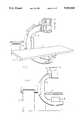
- FIG. 1is a front pictorial diagram of a portion of an X-ray imaging system employing a dual-slide image intensifier support mechanism constructed in accordance with the preferred embodiment of the present invention.
- FIG. 2is a side pictorial diagram of the portion of the X-ray imaging system illustrated in FIG. 1.
- FIG. 3is a pictorial schematic diagram illustrating the way in which travel of an image intensifier is provided by the dual-slide image intensifier support mechanism of FIGS. 1-3.
- FIG. 4is a detailed pictorial diagram of a portion of the dual-slide image intensifier support mechanism illustrated in FIGS. 1 and 2.
- FIG. 5is a partial sectional diagram illustrating the telescoping relationship between primary and secondary slides of the dual-slide image intensifier support mechanism of FIGS. 1-4.
- FIG. 6is a partial sectional top view of the dual-slide image intensifier support mechanism of FIGS. 1-6.
- FIG. 7is a partial sectional side view of the dual-slide image intensifier support mechanism of FIGS. 1-5.
- FIGS. 1 and 2there are shown pictorial diagrams of a portion of an X-ray imaging system that includes a C-shaped arm 10, encompassing a patient table 12, and supported by a pedastal 11 for both arcuate and rotational motion of the C-shaped arm 10, as illustrated.
- a conventional image intensifier 14is supported at one end of the C-shaped arm 10 above patient table 12 by a dual-slide support mechanism 16 that provides for bi-directional travel of image intensifier 14 in the vertical directions illustrated. It is important that the top and bottom ends of the dual-slide support mechanism 16 not extend beyond the top and bottom ends of image intensifier 14 when image intensifier 14 is positioned at the center of its permitted range of vertical travel, as illustrated in FIGS. 1 and 2.
- FIG. 3there is shown a pictorial schematic diagram illustrating the way in which the dual-slide support mechanism 16, mounted at one end of C-shaped arm 10, operates to provide bi-directional vertical travel of image intensifier 14 through a range that is approximately double the overall length of the dual-slide support mechanism 16.
- a motor 20, mounted within a fixed housing 21,includes a worm gear shaft 22 that drives a worm gear reducer 24.
- Worm gear reducer 24includes a pinion gear 26 that in turn engages a rack 28 that is mounted to a primary slide 30.
- Rack 28extends along substantially the entire length of primary slide 30 to permit a range of travel of primary slide 30 substantially equal to its length.
- a secondary slide 32is arranged in sliding engagement with primary slide 30.
- Image intensifier 14is fixedly mounted to secondary slide 32.
- One end of a belt 34is attached to fixed housing 21 at points 38 that are approximately midway between the top and bottom ends of primary slide 30.
- Belt 34is routed upwardly over a pulley 40 mounted near the top end of primary slide 30 and then downwardly between primary slide 30 and secondary slide 32 to points 39 at which it is fixedly attached to secondary slide 32.
- one end of a belt 42is attached to fixed housing 21 at point 38 and routed downwardly over a pulley 44 that is mounted near the bottom end of primary slide 30 and then upwardly between primary slide 30 and secondary slide 32 to point 39 at which it is also fixedly attached to secondary slide 32. While belts 34 and 42 are illustrated in FIG.
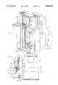
- FIGS. 4-7there is shown the mechanical details of a preferred embodiment of the dual-slide support mechanism of FIGS. 1-3.
- Fixed housing 21is attached to C-shaped arm 10.
- Primary slide 30includes a pair of inwardly facing rail members 50, 52 formed on opposite sides thereof. Rail members 50, 52 are received by a pair of outwardly facing U-shaped rail guides 54, 56 formed in fixed housing 21.
- a multiplicity of ball bearings 58 contained within races formed between rail members 50, 52 and rail guides 54, 56facilitate sliding motion therebetween, thus permitting sliding motion of primary slide 30 with respect to fixed housing 21.
- Primary slide 30also includes a pair of outwardly facing U-shaped rail guides 60, 62 formed on opposite sides thereof.
- Secondary slide 32includes a pair of inwardly facing rail members 64, 66 that are received by U-shaped rail guides 60, 62.
- a multiplicity of ball bearings 68 contained within races formed between rail members 64, 66 and rail guides 60, 62facilitate sliding motion therebetween, thus permitting sliding motion of secondary slide 32 with respect to primary slide 30.
- Secondary slide 32includes a bracket member 70 for mounting the image intensifier 14 illustrated in FIGS. 1-3.
- Motion of secondary slide 32 with respect to primary slide 30is provided by a pair of belts 82, 84 that are routed upwardly along the front face of primary slide 30, over a pair of pulleys 86, 88 that are mounted near the top end of primary slide 30, and then downwardly along the inner face of primary slide 30 to points 93 at which they are fixedly attached to housing 21.
- Belt 82, 84are also routed downwardly along the front face of primary slide 30, over a pair of pulleys 90, 92 mounted near the bottom end of primary slide 30, and the upwardly along the inner face of primary slide 30 to the points 93 at which they are fixedly attached to housing 21.
- Belts 82, 84are fixedly attached to secondary slide 32 at points 94 that are is approximately midway between the top and bottom ends of secondary slide 32.
- Belts 82, 84may be fabricated of a number of commercial materials such as metal, plastic, fabric, etc. Their inner surfaces may be ribbed, as in the case of a timing belt and as illustrated in FIGS. 4-7, or they may have a smooth inner surface. While belts 82, 84 have also been illustrated in FIGS.
- top pulleys 86, 88being fabricated as a single pulley or roller and bottom pulleys 90, 92 also being fabricated as a single pulley or roller.
- FIGS. 4-7Operation of the dual-slide support mechanism illustrated in FIGS. 4-7 is the same as that described above in connection with the schematic diagram of FIG. 3. While the dual-slide support mechanism of the present invention has been described as providing support and extended travel for image intensifier 14, the same mechanism could also provide support and travel for X-ray tube 18, illustrated in FIGS. 1 and 2 as being mounted at the opposite end of C-shaped arm 10 from image intensifier 14.
Landscapes
- Health & Medical Sciences (AREA)
- Life Sciences & Earth Sciences (AREA)
- Medical Informatics (AREA)
- Engineering & Computer Science (AREA)
- Radiology & Medical Imaging (AREA)
- Biomedical Technology (AREA)
- Biophysics (AREA)
- Nuclear Medicine, Radiotherapy & Molecular Imaging (AREA)
- Optics & Photonics (AREA)
- Pathology (AREA)
- Physics & Mathematics (AREA)
- High Energy & Nuclear Physics (AREA)
- Heart & Thoracic Surgery (AREA)
- Molecular Biology (AREA)
- Surgery (AREA)
- Animal Behavior & Ethology (AREA)
- General Health & Medical Sciences (AREA)
- Public Health (AREA)
- Veterinary Medicine (AREA)
- Apparatus For Radiation Diagnosis (AREA)
Abstract
Description
Claims (4)
Priority Applications (1)
| Application Number | Priority Date | Filing Date | Title |
|---|---|---|---|
| US07/493,243US5048069A (en) | 1990-03-14 | 1990-03-14 | Dual-slide support mechanism for X-ray system components |
Applications Claiming Priority (1)
| Application Number | Priority Date | Filing Date | Title |
|---|---|---|---|
| US07/493,243US5048069A (en) | 1990-03-14 | 1990-03-14 | Dual-slide support mechanism for X-ray system components |
Publications (1)
| Publication Number | Publication Date |
|---|---|
| US5048069Atrue US5048069A (en) | 1991-09-10 |
Family
ID=23959458
Family Applications (1)
| Application Number | Title | Priority Date | Filing Date |
|---|---|---|---|
| US07/493,243Expired - Fee RelatedUS5048069A (en) | 1990-03-14 | 1990-03-14 | Dual-slide support mechanism for X-ray system components |
Country Status (1)
| Country | Link |
|---|---|
| US (1) | US5048069A (en) |
Cited By (27)
| Publication number | Priority date | Publication date | Assignee | Title |
|---|---|---|---|---|
| FR2684865A1 (en)* | 1991-12-17 | 1993-06-18 | Sopha Medical | HEIGHT ADJUSTABLE BED. |
| US5237600A (en)* | 1990-11-20 | 1993-08-17 | Kabushiki Kaisha Toshiba | Patient support table for radiographing with X-ray camera |
| USD378133S (en)* | 1995-03-03 | 1997-02-18 | Kabushiki Kaisha Toshiba | X-ray camera for medical treatment |
| US6147352A (en)* | 1998-02-23 | 2000-11-14 | Digirad Corporation | Low profile open ring single photon emission computed tomographic imager |
| FR2808855A1 (en)* | 2000-05-09 | 2001-11-16 | Ge Med Sys Global Tech Co Llc | BELT TENSIONER WITH INTEGRATED SAFETY AGAINST RUPTURE AND RELAXATION OF THE BELT, AND RADIOLOGY DEVICE EQUIPPED WITH SUCH A BELT TENSIONER |
| US6364525B1 (en)* | 1999-06-10 | 2002-04-02 | Siemens Elema Ab | X-ray examination apparatus with a lifting and rotating device for an apparatus component |
| US6374937B1 (en)* | 1998-05-29 | 2002-04-23 | John Galando | Motorized support for imaging means and methods of manufacture and use thereof |
| KR100418974B1 (en)* | 1994-12-20 | 2004-07-15 | 오이씨 메디칼 시스템즈 인코퍼레이티드 | Method for manufacturing mobile C-arm device for X-ray diagnostic equipment and mobile C-arm device for X-ray diagnostic equipment |
| US20050281388A1 (en)* | 2004-06-08 | 2005-12-22 | General Electric Company | Systems, methods and apparatus of an extending column |
| US20070078534A1 (en)* | 2005-09-30 | 2007-04-05 | General Electric Company | Systems, methods and apparatus for powered assistance of a motorized support device |
| USD553748S1 (en)* | 2004-11-26 | 2007-10-23 | Kabushiki Kaisha Toshiba | X-ray apparatus for medical treatment |
| USD554257S1 (en)* | 2004-11-26 | 2007-10-30 | Kabushiki Kaisha Toshiba | Flatness detector of an x-ray apparatus for medical treatment |
| USD555243S1 (en)* | 2005-12-29 | 2007-11-13 | Nauchno-Proizvedstvennoe Chastnoe Unitarnoe Predpriyatie Adani | X-ray apparatus for body scanning |
| USD558877S1 (en)* | 2004-11-26 | 2008-01-01 | Kabushiki Kaisha Toshiba | X-ray apparatus for medical treatment |
| US20080113836A1 (en)* | 2006-11-14 | 2008-05-15 | General Electric Company, A New York Corporation | Automatic tensioning mount for belts |
| US20080232552A1 (en)* | 2007-03-22 | 2008-09-25 | General Electric Company | Systems, methods and apparatus of an image receptor arm |
| FR2918552A1 (en)* | 2007-07-12 | 2009-01-16 | Gen Electric | X-RAY APPARATUS |
| US20090180592A1 (en)* | 2008-01-10 | 2009-07-16 | Stefan Gross | C-arm mounted on a robotic arm |
| US20090185662A1 (en)* | 2008-01-10 | 2009-07-23 | Stefan Gross | C-arm mounted on a robotic arm |
| EP2092890A4 (en)* | 2006-12-05 | 2010-03-17 | Hitachi Medical Corp | X-RAY FLUOROSCOPE TABLE AND X-RAY FLUOROSCOPE SYSTEM |
| EP1376108B1 (en)* | 2002-06-17 | 2012-08-15 | Rigaku Corporation | X-ray diffractometer comprising a C-arm for examining an array of crystals |
| US20120207282A1 (en)* | 2011-02-15 | 2012-08-16 | Toshiba Medical Systems Corporation | X-ray imaging apparatus |
| US10499861B2 (en) | 2017-09-06 | 2019-12-10 | Zap Surgical Systems, Inc. | Self-shielded, integrated-control radiosurgery system |
| JP2022523431A (en)* | 2019-03-04 | 2022-04-22 | ボスケリネ ドゥッチョ | Operating table with integrated imaging device |
| US11684446B2 (en) | 2019-02-27 | 2023-06-27 | Zap Surgical Systems, Inc. | Device for radiosurgical treatment of uterine fibroids |
| US11826582B2 (en) | 2017-05-05 | 2023-11-28 | Zap Surgical Systems, Inc. | Revolving radiation collimator |
| US12246192B2 (en) | 2021-02-01 | 2025-03-11 | Zap Surgical Systems, Inc. | Inverse planning device and methods for radiation treatment |
Citations (7)
| Publication number | Priority date | Publication date | Assignee | Title |
|---|---|---|---|---|
| US3976885A (en)* | 1975-03-18 | 1976-08-24 | Picker Corporation | Tomography system having nonconcurrent, compound axial scanning |
| US4358856A (en)* | 1980-10-31 | 1982-11-09 | General Electric Company | Multiaxial x-ray apparatus |
| US4363128A (en)* | 1980-09-29 | 1982-12-07 | John K. Grady | X-Ray drive apparatus |
| US4635284A (en)* | 1984-07-12 | 1987-01-06 | U.S. Philips Corporation | X-ray examination apparatus comprising a C-shaped or U-shaped support for the X-ray source and detector |
| US4741015A (en)* | 1986-12-05 | 1988-04-26 | B. C. Medical Compagnie Limitee | Universal X-ray unit |
| US4866751A (en)* | 1987-10-06 | 1989-09-12 | U.S. Philips Corporation | Radiological device of the pivoting type |
| US4884293A (en)* | 1988-01-19 | 1989-11-28 | Kabushiki Kaisha Toshiba | X-ray photographing apparatus |
- 1990
- 1990-03-14USUS07/493,243patent/US5048069A/ennot_activeExpired - Fee Related
Patent Citations (7)
| Publication number | Priority date | Publication date | Assignee | Title |
|---|---|---|---|---|
| US3976885A (en)* | 1975-03-18 | 1976-08-24 | Picker Corporation | Tomography system having nonconcurrent, compound axial scanning |
| US4363128A (en)* | 1980-09-29 | 1982-12-07 | John K. Grady | X-Ray drive apparatus |
| US4358856A (en)* | 1980-10-31 | 1982-11-09 | General Electric Company | Multiaxial x-ray apparatus |
| US4635284A (en)* | 1984-07-12 | 1987-01-06 | U.S. Philips Corporation | X-ray examination apparatus comprising a C-shaped or U-shaped support for the X-ray source and detector |
| US4741015A (en)* | 1986-12-05 | 1988-04-26 | B. C. Medical Compagnie Limitee | Universal X-ray unit |
| US4866751A (en)* | 1987-10-06 | 1989-09-12 | U.S. Philips Corporation | Radiological device of the pivoting type |
| US4884293A (en)* | 1988-01-19 | 1989-11-28 | Kabushiki Kaisha Toshiba | X-ray photographing apparatus |
Cited By (41)
| Publication number | Priority date | Publication date | Assignee | Title |
|---|---|---|---|---|
| US5237600A (en)* | 1990-11-20 | 1993-08-17 | Kabushiki Kaisha Toshiba | Patient support table for radiographing with X-ray camera |
| FR2684865A1 (en)* | 1991-12-17 | 1993-06-18 | Sopha Medical | HEIGHT ADJUSTABLE BED. |
| WO1993011705A1 (en)* | 1991-12-17 | 1993-06-24 | Sopha Medical | Height adjustable bed |
| US5490296A (en)* | 1991-12-17 | 1996-02-13 | Sopha Medical | Height-adjustable bed |
| KR100418974B1 (en)* | 1994-12-20 | 2004-07-15 | 오이씨 메디칼 시스템즈 인코퍼레이티드 | Method for manufacturing mobile C-arm device for X-ray diagnostic equipment and mobile C-arm device for X-ray diagnostic equipment |
| USD378133S (en)* | 1995-03-03 | 1997-02-18 | Kabushiki Kaisha Toshiba | X-ray camera for medical treatment |
| US6147352A (en)* | 1998-02-23 | 2000-11-14 | Digirad Corporation | Low profile open ring single photon emission computed tomographic imager |
| US6374937B1 (en)* | 1998-05-29 | 2002-04-23 | John Galando | Motorized support for imaging means and methods of manufacture and use thereof |
| US6364525B1 (en)* | 1999-06-10 | 2002-04-02 | Siemens Elema Ab | X-ray examination apparatus with a lifting and rotating device for an apparatus component |
| FR2808855A1 (en)* | 2000-05-09 | 2001-11-16 | Ge Med Sys Global Tech Co Llc | BELT TENSIONER WITH INTEGRATED SAFETY AGAINST RUPTURE AND RELAXATION OF THE BELT, AND RADIOLOGY DEVICE EQUIPPED WITH SUCH A BELT TENSIONER |
| US6382834B2 (en) | 2000-05-09 | 2002-05-07 | Ge Medical Systems Global Technology Company, Llc | Belt tensioner and a radiology apparatus equipped with such a belt |
| EP1376108B1 (en)* | 2002-06-17 | 2012-08-15 | Rigaku Corporation | X-ray diffractometer comprising a C-arm for examining an array of crystals |
| US7497625B2 (en)* | 2004-06-08 | 2009-03-03 | General Electric Company | Systems, methods and apparatus of an extending column |
| US20050281388A1 (en)* | 2004-06-08 | 2005-12-22 | General Electric Company | Systems, methods and apparatus of an extending column |
| USD553748S1 (en)* | 2004-11-26 | 2007-10-23 | Kabushiki Kaisha Toshiba | X-ray apparatus for medical treatment |
| USD554257S1 (en)* | 2004-11-26 | 2007-10-30 | Kabushiki Kaisha Toshiba | Flatness detector of an x-ray apparatus for medical treatment |
| USD558877S1 (en)* | 2004-11-26 | 2008-01-01 | Kabushiki Kaisha Toshiba | X-ray apparatus for medical treatment |
| US20070078534A1 (en)* | 2005-09-30 | 2007-04-05 | General Electric Company | Systems, methods and apparatus for powered assistance of a motorized support device |
| US7519441B2 (en) | 2005-09-30 | 2009-04-14 | General Electric Company | Systems, methods and apparatus for powered assistance of a motorized support device |
| USD555243S1 (en)* | 2005-12-29 | 2007-11-13 | Nauchno-Proizvedstvennoe Chastnoe Unitarnoe Predpriyatie Adani | X-ray apparatus for body scanning |
| US20080113836A1 (en)* | 2006-11-14 | 2008-05-15 | General Electric Company, A New York Corporation | Automatic tensioning mount for belts |
| US8128074B2 (en) | 2006-11-14 | 2012-03-06 | General Electric Company | Automatic tensioning mount for belts |
| US20100296626A1 (en)* | 2006-12-05 | 2010-11-25 | Atsushi Hibino | X-ray fluoroscope table and x-ray fluoroscope system |
| US8052325B2 (en) | 2006-12-05 | 2011-11-08 | Hitachi Medical Corporation | X-ray fluoroscope table and X-ray fluoroscope system |
| EP2092890A4 (en)* | 2006-12-05 | 2010-03-17 | Hitachi Medical Corp | X-RAY FLUOROSCOPE TABLE AND X-RAY FLUOROSCOPE SYSTEM |
| US7566170B2 (en) | 2007-03-22 | 2009-07-28 | Matthew Aaron Halsmer | Systems, methods and apparatus of an image receptor arm |
| US20080232552A1 (en)* | 2007-03-22 | 2008-09-25 | General Electric Company | Systems, methods and apparatus of an image receptor arm |
| US7748899B2 (en) | 2007-07-12 | 2010-07-06 | General Electric Company | X-ray device |
| FR2918552A1 (en)* | 2007-07-12 | 2009-01-16 | Gen Electric | X-RAY APPARATUS |
| US20090180592A1 (en)* | 2008-01-10 | 2009-07-16 | Stefan Gross | C-arm mounted on a robotic arm |
| US7938579B2 (en)* | 2008-01-10 | 2011-05-10 | Siemens Aktiengesellschaft | C-arm mounted on a robotic arm |
| US7905658B2 (en)* | 2008-01-10 | 2011-03-15 | Siemens Aktiengesellschaft | C-arm mounted on a robotic arm |
| US20090185662A1 (en)* | 2008-01-10 | 2009-07-23 | Stefan Gross | C-arm mounted on a robotic arm |
| US20120207282A1 (en)* | 2011-02-15 | 2012-08-16 | Toshiba Medical Systems Corporation | X-ray imaging apparatus |
| US11826582B2 (en) | 2017-05-05 | 2023-11-28 | Zap Surgical Systems, Inc. | Revolving radiation collimator |
| US10499861B2 (en) | 2017-09-06 | 2019-12-10 | Zap Surgical Systems, Inc. | Self-shielded, integrated-control radiosurgery system |
| US11844637B2 (en) | 2017-09-06 | 2023-12-19 | Zap Surgical Systems, Inc. | Therapeutic radiation beam detector for radiation treatment systems |
| US12220270B2 (en) | 2017-09-06 | 2025-02-11 | Zap Surgical Systems, Inc. | Imaging systems and methods for image-guided radiosurgery |
| US11684446B2 (en) | 2019-02-27 | 2023-06-27 | Zap Surgical Systems, Inc. | Device for radiosurgical treatment of uterine fibroids |
| JP2022523431A (en)* | 2019-03-04 | 2022-04-22 | ボスケリネ ドゥッチョ | Operating table with integrated imaging device |
| US12246192B2 (en) | 2021-02-01 | 2025-03-11 | Zap Surgical Systems, Inc. | Inverse planning device and methods for radiation treatment |
Similar Documents
| Publication | Publication Date | Title |
|---|---|---|
| US5048069A (en) | Dual-slide support mechanism for X-ray system components | |
| US4475072A (en) | Patient-positioning X-ray table | |
| US4979202A (en) | Support structure for X-ray imaging apparatus | |
| US4841585A (en) | Swingable and slidable bed apparatus | |
| US4501011A (en) | Angulating lateral fluoroscopic suspension | |
| US5013018A (en) | Table positioning for X-ray examinations in plurality of positions | |
| JPH0117690B2 (en) | ||
| US5570409A (en) | Apparatus for X-ray fluoroscopy and fluorography | |
| US6095685A (en) | X-ray radioscopic apparatus | |
| US3215835A (en) | Selectively engageable power-assist for x-ray table components | |
| US5010564A (en) | Dual axis translation mechanism | |
| US4455668A (en) | X-Ray examination apparatus | |
| US4989228A (en) | Radiological examination device | |
| US4408341A (en) | X-Ray examination apparatus having a movable X-ray source | |
| US3244883A (en) | X-ray tubestand | |
| RU99104516A (en) | REGULATING BENDING DEVICE | |
| CA1045726A (en) | Scintillation scanning device | |
| KR20230111515A (en) | X-ray imaging apparatus | |
| JPH07265288A (en) | Imaging device driving mechanism for x-ray radioscopic photographing base | |
| US4618979A (en) | X-ray fluoroscopic/radiographic apparatus | |
| JPS6364213B2 (en) | ||
| US6293607B1 (en) | Light shielding apparatus for rear window of automobile | |
| US4286161A (en) | Film cassette drive mechanism in dental radiographic apparatus for photographing entire jaws | |
| JP3765158B2 (en) | X-ray fluoroscopy table | |
| SU1204207A2 (en) | Apparatus for securing primate for conducting investigations |
Legal Events
| Date | Code | Title | Description |
|---|---|---|---|
| AS | Assignment | Owner name:FISCHER IMAGING CORPORATION, COLORADO Free format text:ASSIGNMENT OF ASSIGNORS INTEREST.;ASSIGNOR:SICZEK, BERNARD W.;REEL/FRAME:005257/0884 Effective date:19900314 | |
| FEPP | Fee payment procedure | Free format text:PAT HLDR NO LONGER CLAIMS SMALL ENT STAT AS SMALL BUSINESS (ORIGINAL EVENT CODE: LSM2); ENTITY STATUS OF PATENT OWNER: LARGE ENTITY | |
| FPAY | Fee payment | Year of fee payment:4 | |
| REMI | Maintenance fee reminder mailed | ||
| LAPS | Lapse for failure to pay maintenance fees | ||
| FP | Lapsed due to failure to pay maintenance fee | Effective date:19990910 | |
| AS | Assignment | Owner name:SILICON VALLEY BANK, CALIFORNIA Free format text:SECURITY INTEREST;ASSIGNOR:FISCHER IMAGING CORPORATION;REEL/FRAME:014344/0008 Effective date:20030611 | |
| AS | Assignment | Owner name:FISCHER IMAGING CORPORATION, COLORADO Free format text:RELEASE;ASSIGNOR:SILICON VALLEY BANK;REEL/FRAME:016323/0708 Effective date:20050224 | |
| STCH | Information on status: patent discontinuation | Free format text:PATENT EXPIRED DUE TO NONPAYMENT OF MAINTENANCE FEES UNDER 37 CFR 1.362 |