US5047668A - Optical walkoff compensation in critically phase-matched three-wave frequency conversion systems - Google Patents
Optical walkoff compensation in critically phase-matched three-wave frequency conversion systemsDownload PDFInfo
- Publication number
- US5047668A US5047668AUS07/543,419US54341990AUS5047668AUS 5047668 AUS5047668 AUS 5047668AUS 54341990 AUS54341990 AUS 54341990AUS 5047668 AUS5047668 AUS 5047668A
- Authority
- US
- United States
- Prior art keywords
- crystal
- crystals
- cavity
- axis
- optical
- Prior art date
- Legal status (The legal status is an assumption and is not a legal conclusion. Google has not performed a legal analysis and makes no representation as to the accuracy of the status listed.)
- Expired - Lifetime
Links
- 230000003287optical effectEffects0.000titleclaimsabstractdescription72
- 238000006243chemical reactionMethods0.000titleclaimsabstractdescription45
- 239000013078crystalSubstances0.000claimsabstractdescription199
- 238000005086pumpingMethods0.000claimsabstractdescription29
- 238000004020luminiscence typeMethods0.000claimsabstractdescription10
- QBLDFAIABQKINO-UHFFFAOYSA-Nbarium borateChemical compound[Ba+2].[O-]B=O.[O-]B=OQBLDFAIABQKINO-UHFFFAOYSA-N0.000claimsdescription21
- 230000003993interactionEffects0.000claimsdescription12
- 230000010355oscillationEffects0.000claimsdescription9
- 230000010287polarizationEffects0.000claimsdescription3
- XBJJRSFLZVLCSE-UHFFFAOYSA-Nbarium(2+);diborateChemical compound[Ba+2].[Ba+2].[Ba+2].[O-]B([O-])[O-].[O-]B([O-])[O-]XBJJRSFLZVLCSE-UHFFFAOYSA-N0.000claimsdescription2
- 238000013461designMethods0.000description7
- 239000000463materialSubstances0.000description4
- 230000005855radiationEffects0.000description4
- 229920006395saturated elastomerPolymers0.000description3
- 238000012360testing methodMethods0.000description3
- VYPSYNLAJGMNEJ-UHFFFAOYSA-NSilicium dioxideChemical compoundO=[Si]=OVYPSYNLAJGMNEJ-UHFFFAOYSA-N0.000description2
- 238000010521absorption reactionMethods0.000description2
- 238000011161developmentMethods0.000description2
- 230000018109developmental processEffects0.000description2
- 239000005350fused silica glassSubstances0.000description2
- 230000006872improvementEffects0.000description2
- 238000000034methodMethods0.000description2
- 238000012986modificationMethods0.000description2
- 230000004048modificationEffects0.000description2
- 239000000758substrateSubstances0.000description2
- 229910003327LiNbO3Inorganic materials0.000description1
- 230000009471actionEffects0.000description1
- JNDMLEXHDPKVFC-UHFFFAOYSA-Naluminum;oxygen(2-);yttrium(3+)Chemical compound[O-2].[O-2].[O-2].[Al+3].[Y+3]JNDMLEXHDPKVFC-UHFFFAOYSA-N0.000description1
- 230000005540biological transmissionEffects0.000description1
- BJQHLKABXJIVAM-UHFFFAOYSA-Nbis(2-ethylhexyl) phthalateChemical compoundCCCCC(CC)COC(=O)C1=CC=CC=C1C(=O)OCC(CC)CCCCBJQHLKABXJIVAM-UHFFFAOYSA-N0.000description1
- 230000008859changeEffects0.000description1
- 238000000576coating methodMethods0.000description1
- 230000001427coherent effectEffects0.000description1
- 230000003247decreasing effectEffects0.000description1
- 238000005259measurementMethods0.000description1
- 238000005457optimizationMethods0.000description1
- 238000009304pastoral farmingMethods0.000description1
- 238000002310reflectometryMethods0.000description1
- 238000011160researchMethods0.000description1
- 229910019655synthetic inorganic crystalline materialInorganic materials0.000description1
- 230000002123temporal effectEffects0.000description1
- 229910019901yttrium aluminum garnetInorganic materials0.000description1
Images


Classifications
- G—PHYSICS
- G02—OPTICS
- G02F—OPTICAL DEVICES OR ARRANGEMENTS FOR THE CONTROL OF LIGHT BY MODIFICATION OF THE OPTICAL PROPERTIES OF THE MEDIA OF THE ELEMENTS INVOLVED THEREIN; NON-LINEAR OPTICS; FREQUENCY-CHANGING OF LIGHT; OPTICAL LOGIC ELEMENTS; OPTICAL ANALOGUE/DIGITAL CONVERTERS
- G02F1/00—Devices or arrangements for the control of the intensity, colour, phase, polarisation or direction of light arriving from an independent light source, e.g. switching, gating or modulating; Non-linear optics
- G02F1/35—Non-linear optics
- G02F1/39—Non-linear optics for parametric generation or amplification of light, infrared or ultraviolet waves
- G—PHYSICS
- G02—OPTICS
- G02F—OPTICAL DEVICES OR ARRANGEMENTS FOR THE CONTROL OF LIGHT BY MODIFICATION OF THE OPTICAL PROPERTIES OF THE MEDIA OF THE ELEMENTS INVOLVED THEREIN; NON-LINEAR OPTICS; FREQUENCY-CHANGING OF LIGHT; OPTICAL LOGIC ELEMENTS; OPTICAL ANALOGUE/DIGITAL CONVERTERS
- G02F1/00—Devices or arrangements for the control of the intensity, colour, phase, polarisation or direction of light arriving from an independent light source, e.g. switching, gating or modulating; Non-linear optics
- G02F1/35—Non-linear optics
- G02F1/37—Non-linear optics for second-harmonic generation
Definitions
- the present inventionis directed to walk-off compensation in optical frequency conversion systems such as parametric oscillators, second harmonic generators, sum frequency generators, and difference frequency generators.
- BBO crystalshave a relatively large birefringence which enables phase matching very close to their ultraviolet cutoff at 190 nm.
- thisleads to a large walkoff angle between the extraordinary pumping beam and the ordinary signal and idler beams which limits conversion efficiency by reducing the effective interaction length in the crystal.
- Similar walkoff problemsexist in other critically phasematched three-wave conversion systems.
- the present inventionis directed to optical conversion systems utilizing nonlinear crystals in such a way as to overcome the difficulties exhibited with prior critically phasematched systems and to provide significantly improved performance in such systems.
- the inventionutilizes one or more pairs of nonlinear optical crystals in a linear cavity, the crystals in each pair being so aligned as to cause each crystal to compensate for the walkoff produced by the other, thereby achieving a substantial improvement in conversion efficiency.
- an optical parametric oscillatorincludes a pair of nonlinear crystals such as BBO are arranged in an oscillator cavity, defined by two end mirrors, the crystals being axially aligned between the two mirrors. Interposed between the crystals and the end mirrors are a pair of pump steering mirrors which direct a pumping beam into the oscillator cavity, through the two BBO crystals, and back out of the cavity, without the pumping wavelength being incident on the end mirrors.
- the cavity end mirrorsare standard, low damage threshold, broadband mirrors, with one being a dielectric high reflector and the other being a 50% output coupler.
- the two crystalsare placed on separate rotation mounts and are set to the phase matching angle corresponding to the desired output wavelengths.
- the laser pumping beam enters the cavityis reflected off a first steering mirror, and passes through the two nonlinear crystals, where frequency conversion takes place to produce signal and idler beam oscillator along the axis of the cavity.
- the pumping beamthen is directed out of the cavity by a second steering mirror in the cavity.
- the steering mirrorsare transparent to signal and idler beams produced in the crystals, so these signals can oscillate along the cavity axis, and an output beam can be obtained through the output coupler end mirror.
- the conversion efficiency of the crystals in the oscillatordepends, on the interaction of the pump and signal beams within the crystals, and it has been found that this efficiency is limited by the angle between the incident pump extraordinary beam and the signal beam. This angle produces walkoff of the incident pump beam with respect to the signal beam, so that interaction between the beams only occurs over a limited length of the nonlinear crystal.
- the second crystalis located in axial aligment with the cavity but has its optical axis oppositely disposed. This produces an opposite angle between the incident pump beam and the signal beam than the angle produced in the first crystal. As a result, the extraordinary pump beam which walks off the ordinary signal and idler beams of the first crystal then walks on them in the second crystal, thereby increasing the interaction of the beams and increasing conversion efficiency.
- Tuning of the deviceis performed by rotating the two crystals about their respective tuning axes in opposite directions to maintain phase matching and to maintain the relationship between the axes of the two crystals.
- the conversion efficiency of the deviceis defined as the ratio of the total output power passing through the cavity end mirrors to the pump power incident on the first pump steering mirror in the cavity.
- the configuration of the present inventionrevealed a significant increase in this efficiency.
- Similar increases in conversion efficiencyare obtained in other critically phasematched, three-wave frequency converters through the use of the walkoff compensation of the present invention, wherein pairs of crystals are oppositely disposed along the axis of a cavity.
- Examples of such systemsare second harmonic generators, wherein an input beam having a fundamental frequency W1 produces a second harmonic frequency beam ⁇ 2 ; sum frequency generators, wherein two input beams of frequencies ⁇ 1 and ⁇ 2 produce a single frequency output beam ⁇ 3 which is the sum of ⁇ 1 and ⁇ 2 ; and difference frequency generators, wherein two input beams of frequencies ⁇ 1 and ⁇ 2 produce a single frequency output beam which is the difference between ⁇ 1 and ⁇ 2 .
- more than one pair of crystalsmay be used in a cavity; any number of pairs of oppositely disposed crystals may be incorporated in the cavity to improve the conversion efficiency of the system.
- one of the cavity end mirrorsmay be replaced with a grating having its grooves perpendicular to the polarization of the signal wave. It was found that the addition of such a grating clamps the linewidth at 3 Angstroms, allowing the device to be operated throughout its tuning range with linewidths that do not exceed this value.
- FIG. 1is a diagrammatic top view of a walkoff-compensated, two-crystal optical parametric oscillator cavity
- FIG. 2is a diagrammatic, enlarged side view of the crystals of the cavity of FIG. 1;
- FIG. 3is a graphical illustration of the ratio of the standard deviation of the fluctuation of optical parametric oscillator pulse energies to the fluctuation of the pump pulse energies, versus pumping, the dashed line denoting the point where the fluctuation of the oscillator output is equal to that of the pump;
- FIG. 4is a graphical illustration of optical parametric oscillator conversion efficiency versus pumping
- FIG. 5is a graphical illustration of optical parametric oscillator linewidth versus signal wavelength
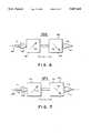
- FIG. 6is a diagrammatic illustration of a walkoff-compensated second harmonic generator in accordance with the present invention.
- FIG. 7is a diagrammatic illustration of a walkoff-compensated sum frequency generator in accordance with the present invention.
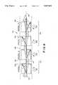
- FIG. 8is a diagrammatic illustration of a walkoff-compensated scheme utilizing multiple crystal pairs.
- an optical parametric oscillator 10which includes an optical cavity 12 defined at its opposite ends by a pair of cavity end mirrors 14 and 16 having facing reflective parallel or slightly concave surfaces 18 and 20, respectively, in conventional optical parametric oscillator configuration.
- the mirrorsare mounted with their faces perpendicular to the cavity axis.
- Mounted in the cavity 12 between mirrors 14 and 16are a pair of nonlinear optical crystals 22 and 24.
- the two crystalsare mounted for rotation about their respective crystallographic X axes 26 and 28 to provide tunability for the oscillator.
- the cavity arrangement for oscillator 10is the same as that described in detail in U.S. patent application Ser. No. 07/455,179, filed Dec. 22, 1989 of Bosenberg et al, the disclosure of which is incorporated herein by reference.
- the crystals 22 and 24are a low temperature phase beta barium metaborate (BBO).
- BBObeta barium metaborate
- the two BBO crystals used in a test of the present inventionwere grown using the top seeded solution growth technique described by L. K. Chen, W. R. Bosenberg, and C. L. Tang in the Journal of Crystal Growth, Vol. 89, p. 553, 1988.
- the first crystal 22is provided with an aperture of 10 ⁇ 10 mm 2 with an interaction length of 11.5 mm and is cut for type I phasematching with an angle of 30.2° between the entrance face normal and the optic axis of the crystal. This optic axis is illustrated in FIG. 2 by the arrow 30 for crystal 22.
- Crystal 24is a 10 ⁇ 10 mm 2 crystal with an interaction length of 9.5 mm and is cut for type I phase matching with an angle of 29.3° between the entrance face normal and its optic axis 32 (FIG. 2).
- the crystals 22 and 24are placed on separate rotation mounts, diagrammatically illustrated at 34 and 36 so that they are rotatable about axes 26 and 28, respectively, which are perpendicular to the axis of cavity 12. This latter axis is illustrated by line 38 in FIGS. 1 and 2.
- the two crystalsare rotatably adjusted so that their optical axes 30 and 32 are oppositely disposed with respect to cavity axis 38, and are both set to the phasematching angle ⁇ pm with respect to axis 38, which angle corresponds to the desired output wavelength.
- This angleis illustrated at 40 in FIG. 2 for crystal 22 and at 42 for crystal 24, and is on opposite sides of the cavity axis 38 for the two crystals so that the crystals are arranged with their respective optic axes at an angle of 2 ⁇ pm relative to one another.
- Tuning of the deviceis easily performed by rotating the two crystals 22 and 24 about their tuning axes 26 and 28 in opposite directions, as indicated by arrows 44 and 46 to maintain phase matching.
- the oscillator 10is pumped by a source 48, which preferably is a commercially available Q-switched neodymium-doped yttrium aluminum garnet (Nd:YAG) laser.
- the pumping sourceproduces an output pumping signal W p indicated by pump beam 50.
- the pumping pulses in beam 50may be, for example, the third harmonic of the laser output, and the beam may have a diameter of 1.0 mm, with the pulses having a pulse duration of 7 ns.
- the pump beam 50is directed into the oscillator cavity 12 to a first pump steering mirror 52 set at Brewster's angle ⁇ B , indicated by angle 54 in FIG. 1, with respect to the direction of the pump beam.
- the mirror 52is located in cavity 12 and is also set at Brewster's angle with respect to the cavity axis 38 so that the pump beam 50 is directed along axis 38 from mirror 52 to impinge on the first crystal 22.
- the first steering mirror 52is a standard, commercially available 45° incidence mirror, with its reflective surface being greater than 98% reflective at the pumping wavelength of 355 nm.
- the surface of mirror 52is transmissive at the parametrically generated oscillator output beam wavelength of interest. Typically, such a mirror may be transmissive at wavelengths up to about 2.2 micrometers, where the absorption of infrared by the fused silica substrate for the mirror cuts off the transmissivity.
- the pump beam 50is directed by mirror 52 along axis 38 to a first end 56 of the first crystal 22, passes through the crystal and exits from its second end 58, as illustrated in FIG. 2.
- the pump beam 50then enters the first end 60 of the second crystal 24, passes through that crystal and exits from its second end 62.
- the pump beam exiting from end 62 of crystal 24then strikes a second pump steering mirror 64 which is similar to mirror 52, with its surface also set at Brewster's angle with respect to the axis 38.
- the surface of mirror 64is highly reflective at the pumping pulse wavelength so that it deflects beam 50 out of cavity 12, as illustrated in FIG. 1.
- the mirror 64is transmissive at the parametrically generated wavelength of interest.
- the cavity end mirror 14is a standard, low damage threshold, broad band, dielectric high reflector having a reflectivity of over 90% at wavelengths of between 480 and 700 nm.
- Cavity end mirror 16is a 50% output coupler. All of the mirrors 14, 16, 52 and 64 transmit over 90% of the infrared idler waves which are at frequency ⁇ i , thereby insuring singly resonated operation.
- the cavity lengthin one embodiment of the OPO of this invention, was 55 nm between the surfaces 18 and 20 of mirrors 14 and 16, allowing about 17 round trips of the resonated wave.
- the pumping beam 50produces optical parametric luminescence and frequency conversion in crystal 22 at wavelengths which depend upon the rotational angle of the crystal about its axis 26, and thus depend upon angle ⁇ pm .
- This luminescenceis emitted from the end 58 of the crystal along the cavity axis 38 as signal and idler beams ⁇ s and ⁇ i .
- These beamsare transmitted into the second crystal 24 along with the pumping beam 50 to produce further optical parametric luminescence and frequency conversion in that crystal, again at wavelengths which depend upon the rotational angle of crystal 24 about its axis 28.
- the two crystalsare adjusted so that the signal and idler beams produced by crystal 22 are phase matched with those produced by crystal 24 so that desired parametric oscillation is produced in the cavity 12.
- the K vector wavefront of the pump beam 50 and of the signal beam produced in the crystal 22 by the pumping action of beam 50moves straight through the crystal 22 and the crystal 24, as indicated by the signal and idler beam path 66.
- the extraordinary energy wave and the ordinary energy wave of a laserrespond differently to the index of refraction of the medium in which they travel, and thus do not travel in parallel through a nonlinear birefringent crystal, with the angle between the energy waves being related to the amount of birefringence. In a material such as BBO, this is a relatively large angle.
- the pump beam ⁇ pis an extraordinary wave
- the signal and idler waves ⁇ s and ⁇ i on path 66 in the crystal 22 and in the crystal 24are ordinary waves.
- the pump wavesmust interact with the signal and idler waves in the crystal in order to produce frequency conversion and the more interaction, the better the conversion.
- the required interactionis produced by critical phase matching of the pump with the signal beams which is achieved by adjusting the angle ⁇ pm of the extraordinary wave of the pump with respect to the optical axis of the crystal indicated by 30 for crystal 22 and by 32 for crystal 24.
- the direction in which the extraordinary wave energy travels through the crystalis, however, different than the direction of the ordinary wave, as illustrated in FIG. 2 by angle 68, with the result that the extraordinary wave walks off the crystal; i.e., moves transversely with respect to the optical axis and in a direction away from that axis, as indicated in FIG. 2 by the pump wave at 50'.
- the pump beamenters the crystal 22 in a direction normal to face 56
- the extraordinary energy wavemoves at an angle 68 with respect to the direction of the ordinary signal and idler waves, due to the change in the index of refraction as the pum beam 50 enters the crystal.
- this walkoff angle 68can be 3° to 5°, thus limiting the interaction between the pump and the signal waves as the pump wave passes through the crystal. This effectively limits the length of the crystal and reduces its conversion efficiency.
- this limitationis overcome by the provision of the second crystal 24 which is mounted in the path of the pump beam 50 and is aligned with the signal beam ⁇ s from crystal 22.
- the second crystal 24has its optical axis 32 disposed oppositely, with respect to cavity axis 38, than the axis of crystal 22.
- angles 40 and 42 of the two crystals 22 and 24, respectivelyare on opposite sides of the axis 38 with the angle between optical axes 30 and 32 being the sum of the angles 40 and 42.
- This opposite disposition of the two crystalsproduces walkoff in crystal 24 at the same angle 68' with respect to axis 38 as is produced in crystal 22, but in a direction with respect to the cavity axis which is opposite to .
- the conversion efficiency n of the devicewas determined by measuring the ratio of the total oscillator output power passing through exit mirrors 14 and 16 to the pump power (P) incident on the steering mirror 52 from source 48. The efficiency of the device so determined provides the total usable power converted from the pump inlet to the signal and idler wavelengths.
- the oscillation threshold power (P th ) for the devicewas measured by reducing the pump power until only occasional oscillator flashes were observed.
- FIG. 4is a graph which illustrates the total usable optical parametric oscillator (OPO) conversion efficiency versus the pumping power as a ratio of threshold power for the oscillator 10.
- OPOoptical parametric oscillator
- the datawas obtained by a high quality, central-Airy-disc using a 1 mm diameter pump beam, the data points of which are indicated by triangles. Data was also obtained with a larger 1.5 mm beam of somewhat poorer spatial quality, the data points of which are indicated in the Figure by circles. Both sets of data saturate at about 32% efficiency.
- the oscillation thresholdis 1.7 mJ per pulse (27 MW per cm 2 ) for the 1 mm beam and 5.0 mJ per pulse (about 37 MW per cm 2 ) for the 1.5 mm beam. With the larger beam, as much as 7 mJ per pulse of OPO output was observed (with 21 mJ per pulse of pump).
- the solid line 70 in FIG. 4is the theoretical conversion efficiency for a singly resonant oscillator obtained by integrating plane wave solutions over a Gaussian intensity profile, with two modifications.
- a temporal integralmust be performed, yielding a factor of about (1-P th /P).
- a scale factormust be used to account for reflection losses of the uncoated crystals and the intracavity pump steering mirrors. For the cavity used in the test, this factor was estimated to be about 0.65, so roughly one-third of the parametrically generated light was lost to intracavity reflections, which implies that the peak internal conversion efficiency of the device is about 50%.
- the agreement between the theoretical curve and the experimental datawas quite good for both pump beams, the poorer spatial quality of the larger beam manifesting itself in the form of a higher threshold intensity.
- the dashed curve 72 in FIG. 4represents an estimate of the usable conversion efficiency of a device with the lower intracavity losses obtained by using anti-reflection coated BBO crystals. With careful optimization of intracavity coatings, about 50% of the input pump could be converted into useful output. Although the efficiency data is for a particular signal and idler pair, angle tuning of the device is very straightforward. A single set of mirrors and a single pair of crystals allows continuous tuning over the range of 0.42 to 2.3 micrometers, with better than 24% conversion efficiency throughout. At idler wavelengths longer than 2.4 micrometers, the loss due to the onset of absorption in the BBO crystals and the fused silica pump mirror substrates increases the oscillation threshold and limits the efficiency.
- the two-crystal, walkoff-compensated oscillator 10 of FIG. 1was directly compared to two other configurations using identical crystals and mirrors under identical pump conditions.
- a conventional one-crystal design and a two-crystal design with the two optic axes parallelwere tested. Table I gives a summary of these results.
- the walkoff-compensated scheme of FIG. 1clearly demonstrates lower thresholds and higher maximum efficiencies.
- the value of the saturated maximum efficiency in the one crystal oscillatoragrees well with previously reported results.
- the results illustrated in Table Isuggest that for the BBO oscillator, the walkoff-compensated, two-crystal design of the present invention is more efficient than the one-crystal design, independent of the quality of the pump source.
- the pulse-to-pulse fluctuation of the oscillator outputwas determined using a fast photodiode (rise time less than 200 ps) to measure the energies of individual pulses.
- the variation of the OPO pulse energieswas compared to that of the pump pulse energies.
- the linewidth of the output of oscillator 10is an important parameter.
- the linewidth of the two-crystal OPO outputwas measured with a 0.5 m monochromator whose wavelength resolution was approximately 0.3 Angstroms.
- the dashed line 74 in FIG. 5, calculated using published Sellmeier coefficients,is in good agreement with experimental data indicated by triangles that show the dramatic increase in the OPO linewidth as the device is tuned toward the degenerate point typical of all type I OPOs.
- the linewidth measurementsare full-width-half-maximum values, and the observed linewidths vary from 1.5 Angstroms far from degeneracy to over 100 Angstroms at degeneracy.
- external linewidth controlis needed.
- the required controlcan be obtained by replacing, for example, the cavity mirror 14 (FIG. 1) with a grating.
- a Milton-Roy Number 35-53-290 gratinghas 1800 grooves per millimeter, and a blaze angle of 26.7°. Such a grating was placed with its grooves perpendicular to the polarization of the signal wave 66 for improved broadband diffraction efficiency.
- the most efficient cavityinvolves placing the grating in the first order Littrow configuration.
- the solid line 76 drawn through the data in FIG. 5shows that for signal wavelengths whose unnarrowed gain bandwidth is less than 3 Angstroms (wavelength less than 500 nm), the OPO gain controls the linewidth, while for signal wavelengths whose gain bandwidth is greater than 3 Angstroms (wavelength greater than 500 nm), the grating clamps the linewidth at 3 Angstroms. Due to the excellent grating efficiency in the Littrow configuration, the line-narrowed OPO conversion efficiency is as high as 25%. Hence, the device can be operated throughout its tuning range with linewidths of 1.5 to 3.0 Angstroms without sacrificing significant amounts of output power.
- the second order Littrow configurationyields linewidths only slightly narrower than the first order configuration, but with a noticeable increase in oscillator threshold due to the decreasing grating efficiency.
- linewidths of 0.3 Angstromswere measured with a scanning Fabry-Perot Etalon. Due to the poor efficiency of the grating at grazing incidence (about 6% per pass) the oscillator threshold is nearly double that of the first order Littrow scheme and hence the conversion efficiency of the OPO is significantly lower. The improvement in linewidth, however, makes the Littman design a good option for lower power, high-resolution applications.
- a single gratingcan be used to achieve narrow line-widths in a BBO optical parametric oscillator.
- FIG. 6illustrates in diagrammatic form a walkoff compensated second harmonic generator (SHG) 80, wherein a pair of non-linear crystals 82 and 84 such as BBO are arranged along an axis 86 defined by a pump beam 88.
- the crystalsare aligned with the axis 86 in the manner described above for crystals 22 and 24, with each crystal being mounted with its optical axis (90, 92, respectively) at a phasematching angle with respect to the direction of travel of the generated signal beams, i.e., with respect to axis 86.
- the input beam ⁇ 1 which impinges on the first crystal 82is phasematched with the signal beam ⁇ 2 produced by the crystals, so that the output signal beam 94 is the second harmonic of the input beam.
- the input beamwalks off the signal beam in crystal 82, as explained above with respect to FIG. 1, but the second crystal 84 has its optical axis 92 oppositely disposed with respect to the optical axis 90 of crystal 82. This causes the input beam to walk on the signal beam in crystal 84, thereby extending the interaction between the beams within the crystals and increasing the conversion efficiency of the system.
- System 100includes a pair of crystals 102 and 104 oppositely disposed with respect to a common axis 106.
- This systemis a sum frequency generator (SFG), wherein two input pump beams at frequencies ⁇ 1 and ⁇ 2 , indicated at 108, are combined in crystals 102 and 104 to generate a single frequency output ⁇ 3 at 110 which is the sum of frequencies ⁇ 1 and ⁇ 2 .
- the crystals 102 and 104have their respective optical axes 112 and 114 on opposite sides of the axis 106 so that the input beams ⁇ 1 and ⁇ 2 walk off crystal 102 and walk on crystal 104, in the manner discussed above with respect to FIG. 1.
- a single pair of crystalsprovides walkoff compensation in the manner discussed above, it may be desired to further improve the performance of a frequency conversion system by utilizing plural pairs of crystals, as indicated in the frequency conversion system 120 of FIG. 8.
- two pairs 122 and 124 of crystalsare aligned along the axis 126 of a cavity 128, between cavity end mirrors (not shown).
- Crystals 132 and 134make up the first pair 122, and crystals 136 and 138 make up the second pair 124.
- the crystalshave their optical axes oppositely disposed with respect to the cavity axis, in the manner described with respect to FIG. 1.
- FIG. 1In the illustrated form of FIG.
- an extraordinary wave 140walks off crystal 132, and walks on crystal 134, with respect to the axial signal wave 142.
- the wave 140travels to the second pair of crystals where it walks off the signal wave in crystal 136 and walks on it in crystal 138, again in the manner described with respect to FIG. 1.
- the extraordinary wave and the signal waveinteract for a greater distance in the nonlinear crystals to improve the efficiency of the frequency conversion systems.
Landscapes
- Physics & Mathematics (AREA)
- Nonlinear Science (AREA)
- General Physics & Mathematics (AREA)
- Optics & Photonics (AREA)
- Optical Modulation, Optical Deflection, Nonlinear Optics, Optical Demodulation, Optical Logic Elements (AREA)
Abstract
Description
TABLE I ______________________________________ 1.0 mm diameter Beam 1.5 mm Diameter Beam Maximum Maximum Crystal Threshold Efficiency Threshold Efficiency Configuration (mJ/Pulse) (%) (mJ/Pulse) (%) ______________________________________ Two crystals 2.1 32 5.0 33 Opposing Optic Axes Walkoff- compensated Two crystals 4.1 20 6.0 22 Parallel Optic axes Not Walkoff- compensated One crystal 3.5 21 9.5 18 ______________________________________
TABLE II ______________________________________ OPO Signal Maximum Grating Linewidth Threshold Efficiency Configuration (Angstroms) (mJ/pulse) (%) ______________________________________ No grating 1.5-100 2.0 33 Littrow 1.5-3.0 3.0 25 (first order) Littrow 1.2-2.5 4.0 18 (second order) Littman 0.3 5.5 9 ______________________________________
Claims (17)
Priority Applications (1)
| Application Number | Priority Date | Filing Date | Title |
|---|---|---|---|
| US07/543,419US5047668A (en) | 1990-06-26 | 1990-06-26 | Optical walkoff compensation in critically phase-matched three-wave frequency conversion systems |
Applications Claiming Priority (1)
| Application Number | Priority Date | Filing Date | Title |
|---|---|---|---|
| US07/543,419US5047668A (en) | 1990-06-26 | 1990-06-26 | Optical walkoff compensation in critically phase-matched three-wave frequency conversion systems |
Publications (1)
| Publication Number | Publication Date |
|---|---|
| US5047668Atrue US5047668A (en) | 1991-09-10 |
Family
ID=24167966
Family Applications (1)
| Application Number | Title | Priority Date | Filing Date |
|---|---|---|---|
| US07/543,419Expired - LifetimeUS5047668A (en) | 1990-06-26 | 1990-06-26 | Optical walkoff compensation in critically phase-matched three-wave frequency conversion systems |
Country Status (1)
| Country | Link |
|---|---|
| US (1) | US5047668A (en) |
Cited By (88)
| Publication number | Priority date | Publication date | Assignee | Title |
|---|---|---|---|---|
| US5136597A (en)* | 1991-03-15 | 1992-08-04 | Coherent, Inc. | Poynting vector walk-off compensation in type ii phasematching |
| US5249190A (en)* | 1989-06-01 | 1993-09-28 | Adlas Gmbh & Co. Kg | Frequency-doubled laser |
| US5251059A (en)* | 1991-01-09 | 1993-10-05 | Nec Corporation | Frequency conversion device and method of fabricating the same |
| US5260953A (en)* | 1992-09-08 | 1993-11-09 | Alcon Surgical, Inc. | Tunable solid-state laser |
| US5272709A (en)* | 1992-10-02 | 1993-12-21 | Alcon Surgical, Inc. | Frequency doubled laser having power triggered optimization and regulation |
| US5274650A (en)* | 1990-12-28 | 1993-12-28 | Hoya Corporation | Solid state laser |
| US5276548A (en)* | 1992-12-01 | 1994-01-04 | Eli Margalith | Ring cavity optical parametric apparatus |
| US5278852A (en)* | 1990-10-11 | 1994-01-11 | Kigre, Inc. | Intra-cavity high order harmonic laser |
| US5296960A (en)* | 1993-02-26 | 1994-03-22 | Cornell Research Foundation, Inc. | Intracavity-doubled tunable optical parametric oscillator |
| US5315433A (en)* | 1991-02-28 | 1994-05-24 | Fuji Photo Film Co., Ltd. | Optical wavelength converting apparatus |
| US5321711A (en)* | 1992-08-17 | 1994-06-14 | Alliedsignal Inc. | Segmented solid state laser gain media with gradient doping level |
| US5363388A (en)* | 1991-10-18 | 1994-11-08 | Cedars-Sinai Medical Center | Continuously tunable solid state ultraviolet coherent light source |
| US5371752A (en)* | 1993-05-03 | 1994-12-06 | Powers; Peter E. | Optical parametric oscillation using KTA nonlinear crystals |
| US5377043A (en)* | 1992-05-11 | 1994-12-27 | Cornell Research Foundation, Inc. | Ti:sapphire-pumped high repetition rate femtosecond optical parametric oscillator |
| DE4400095A1 (en)* | 1993-08-24 | 1995-03-02 | Spectra Physics Lasers Inc | Optical parametric oscillator with an unstable resonator |
| US5400173A (en)* | 1994-01-14 | 1995-03-21 | Northrop Grumman Corporation | Tunable mid-infrared wavelength converter using cascaded parametric oscillators |
| US5406408A (en)* | 1993-02-26 | 1995-04-11 | Cornell Research Foundation, Inc. | Intracavity-doubled tunable optical parametric oscillator |
| WO1995025368A1 (en)* | 1994-03-16 | 1995-09-21 | Amoco Corporation | Laser system with collinear process and alignment beams |
| FR2718256A1 (en)* | 1994-03-30 | 1995-10-06 | Hoya Corp | Optical parametric oscillator at BBO with narrow line width using extraordinary resonance. |
| US5477378A (en)* | 1994-08-11 | 1995-12-19 | Spectra-Physics Lasers, Inc. | Multiple crystal non-linear frequency conversion apparatus |
| EP0649049A3 (en)* | 1993-10-19 | 1996-05-01 | Ibm | Wavelength converting device. |
| DE19517753A1 (en)* | 1995-05-15 | 1996-11-21 | Lambda Physik Gmbh | Narrow bandwidth, tunable coherent light source appts. |
| US5579152A (en)* | 1993-12-13 | 1996-11-26 | Cornell Research Foundation, Inc. | Tunable optical parametric oscillator |
| US5611946A (en)* | 1994-02-18 | 1997-03-18 | New Wave Research | Multi-wavelength laser system, probe station and laser cutter system using the same |
| US5659561A (en)* | 1995-06-06 | 1997-08-19 | University Of Central Florida | Spatial solitary waves in bulk quadratic nonlinear materials and their applications |
| US5659419A (en)* | 1994-08-23 | 1997-08-19 | Lambda Physik Gesellschaft Zur Herstellung Von Lasern Mbh | Tunable narrowband optical parametrical oscillator |
| US5661595A (en)* | 1995-04-06 | 1997-08-26 | Lambda Physik Gesellschaft Zur Herstellung Von Lasern Mbh | Tunable, optical parametric oscillator |
| US5663973A (en)* | 1996-05-14 | 1997-09-02 | Lambda Physik Gesellschaft Zur Herstellung Von Lasern Mbh | Tunable narrowband source of a coherent radiation |
| DE19611015A1 (en)* | 1996-03-20 | 1998-01-29 | Lambda Physik Gmbh | Tunable optical parametric oscillator with coupled resonators |
| US5732095A (en)* | 1996-09-20 | 1998-03-24 | Hewlett-Packard Company | Dual harmonic-wavelength split-frequency laser |
| US5734763A (en)* | 1996-09-04 | 1998-03-31 | Hewlett-Packard Company | Compact two-by-n optical components based on bierfringent walk-off crystals |
| US5796513A (en)* | 1995-08-30 | 1998-08-18 | Lambda Physik Gesellschaft Zur Herstellung Von Lasern Mgh | Laser arrangement for generating narrow-band, tunable coherent radiation |
| US5812305A (en)* | 1995-12-01 | 1998-09-22 | California Institute Of Technology | Optical parametric oscillator cavity design |
| US5850407A (en)* | 1997-11-25 | 1998-12-15 | Lightwave Electronics Corporation | Third-harmonic generator with uncoated brewster-cut dispersive output facet |
| JPH11160746A (en)* | 1997-11-26 | 1999-06-18 | Nec Corp | Wavelength conversion method and wavelength conversion element |
| GB2333374A (en)* | 1998-01-14 | 1999-07-21 | Northrop Grumman Corp | An intracavity difference-frequency mixing optical parametric oscillator |
| EP0932811A2 (en)* | 1997-08-21 | 1999-08-04 | Raytheon Company | Portable laser range finder and digital compass assembly |
| US5940418A (en)* | 1996-06-13 | 1999-08-17 | Jmar Technology Co. | Solid-state laser system for ultra-violet micro-lithography |
| US5975183A (en)* | 1998-03-23 | 1999-11-02 | Northrop Grumman Corporation | Repair pressure applicator for in the field damaged aircraft |
| US6005878A (en)* | 1997-02-19 | 1999-12-21 | Academia Sinica | Efficient frequency conversion apparatus for use with multimode solid-state lasers |
| EP0833190A3 (en)* | 1996-09-25 | 2000-09-27 | Terumo Kabushiki Kaisha | Continuously tunable multi wavelength laser |
| US6141538A (en)* | 1998-03-03 | 2000-10-31 | Northrop Grumman Corporation | Transmit detection circuit |
| US6167067A (en)* | 1998-04-03 | 2000-12-26 | Northrop Grumman Corporation | Optical parametric oscillator with monolithic dual PPLN elements with intrinsic mirrors |
| US6172800B1 (en)* | 1997-07-16 | 2001-01-09 | Nec Corporation | Laser wavelength conversion method and device |
| WO2001007964A1 (en)* | 1999-07-27 | 2001-02-01 | Ushio Research Institute Of Technology Inc. | Laser for laser machining |
| US6208673B1 (en)* | 1999-02-23 | 2001-03-27 | Aculight Corporation | Multifunction solid state laser system |
| US6282014B1 (en) | 1999-06-09 | 2001-08-28 | Northrop Grumman Corporation | Cascade optical parametric oscillator for down-conversion |
| US6320886B1 (en)* | 1996-07-12 | 2001-11-20 | The Secretary Of Defence In Her Britannic Majesty's Government Of The United Kingdom Of Great Britian And Northern Ireland | Laser device |
| WO2001081878A3 (en)* | 2000-04-24 | 2002-02-21 | Raytheon Co | Serial optical parametric oscillator |
| JP3273488B2 (en) | 1995-07-25 | 2002-04-08 | 日本電信電話株式会社 | Highly efficient generator of stimulated parametric light |
| WO2002043201A1 (en)* | 2000-11-22 | 2002-05-30 | Visx, Incorporated | Temperature actuated positioning device for non-linear optical elements |
| US6435242B1 (en) | 1998-03-23 | 2002-08-20 | Northrop Grumman Corp | Repair pressure applicator |
| US20020149836A1 (en)* | 2001-04-12 | 2002-10-17 | The Regents Of The University Of California | High gain preamplifier based on optical parametric amplification |
| US20020176472A1 (en)* | 2001-05-22 | 2002-11-28 | Arbore Mark A. | Tunable light source employing optical parametric oscillation near degeneracy |
| US20030043452A1 (en)* | 2001-08-31 | 2003-03-06 | Jenoptik Laser, Optik, Systeme Gmbh | Device for the frequency conversion of a fundamental laser frequency to other frequencies |
| US6544330B2 (en) | 2001-02-14 | 2003-04-08 | The United States Of America As Represented By The Department Of Energy | Bonded, walk-off compensated optical elements |
| WO2003029892A1 (en)* | 2001-09-26 | 2003-04-10 | Lumera Laser Gmbh | Device and method for converting an optical frequency |
| US6573702B2 (en) | 1997-09-12 | 2003-06-03 | New Wave Research | Method and apparatus for cleaning electronic test contacts |
| US20030112493A1 (en)* | 2001-12-13 | 2003-06-19 | The Regents Of The University Of California | High average power scaling of optical parametric amplification through cascaded difference-frequency generators |
| US20030128423A1 (en)* | 2001-12-13 | 2003-07-10 | The Regents Of The University Of California | Nondegenerate optical parametric chirped pulse amplifier |
| US20030147122A1 (en)* | 2001-12-13 | 2003-08-07 | The Regents Of The University Of California | Coherent white light amplification |
| US6608852B2 (en) | 2000-08-25 | 2003-08-19 | Lameda Physik Ag | Gain module for diode-pumped solid state laser and amplifier |
| US6614584B1 (en) | 2000-02-25 | 2003-09-02 | Lambda Physik Ag | Laser frequency converter with automatic phase matching adjustment |
| US20030193710A1 (en)* | 2002-04-15 | 2003-10-16 | Aref Chowdhury | Method and apparatus for generating a sequence of optical wavelength bands |
| US6647034B1 (en)* | 2001-04-30 | 2003-11-11 | Sandia Corporation | Method to improve optical parametric oscillator beam quality |
| US6650682B1 (en) | 1999-04-30 | 2003-11-18 | University Of New Mexico | Bi-directional short pulse ring laser |
| US6697391B2 (en) | 2002-03-28 | 2004-02-24 | Lightwave Electronics | Intracavity resonantly enhanced fourth-harmonic generation using uncoated brewster surfaces |
| US6751010B1 (en) | 2003-04-23 | 2004-06-15 | Itt Manufacturing Enterprises, Inc. | Low finesse, tri-etalon, optical parametric oscillator |
| US6785041B1 (en)* | 2001-10-31 | 2004-08-31 | Konstantin Vodopyanov | Cascaded noncritical optical parametric oscillator |
| US6807200B2 (en)* | 2001-09-25 | 2004-10-19 | Dso National Laboratories | Apparatus for generating laser radiation |
| US20040252300A1 (en)* | 2003-06-12 | 2004-12-16 | Slater Richard C. | Chemical identification by flash spectroscopy |
| US6873454B2 (en) | 2001-12-13 | 2005-03-29 | The Regents Of The University Of California | Hybrid chirped pulse amplification system |
| JP2007133445A (en)* | 2007-02-23 | 2007-05-31 | Sony Corp | Wavelength conversion device |
| US20090028195A1 (en)* | 2007-01-22 | 2009-01-29 | Evans & Sutherland Computer Corporation | System and method for frequency conversion of coherent light |
| US20090041067A1 (en)* | 2007-08-07 | 2009-02-12 | Onyx Optics | Engineered nonlinear optical crystal composites for frequency conversion |
| CN100492149C (en)* | 2003-11-27 | 2009-05-27 | 中国科学院福建物质结构研究所 | Cross stacked laser crystal frequency doubler |
| US20090147349A1 (en)* | 2007-12-11 | 2009-06-11 | Young Optics Inc. | Laser module |
| WO2009082460A3 (en)* | 2007-12-18 | 2009-10-01 | Kla-Tencor Corporation | Enclosure for controlling the enviroment of optical crystals |
| US20100103966A1 (en)* | 2008-01-21 | 2010-04-29 | Tetsuro Mizushima | Wavelength conversion laser, image display device and laser processing device |
| US20110013264A1 (en)* | 2007-08-07 | 2011-01-20 | Onyx Optics, Inc. | Quasi non-critical phase matched and contra-phase matched structures |
| US20110180729A1 (en)* | 2010-01-22 | 2011-07-28 | Newport Corporation | Broadly tunable optical parametric oscillator |
| WO2012148800A1 (en)* | 2011-04-29 | 2012-11-01 | Bae Systems Information And Electronic Systems Integration Inc. | Walk-off compensator with tilt function |
| DE102013113026A1 (en) | 2012-12-18 | 2014-06-18 | Rofin Sinar Laser Gmbh | Device for frequency conversion of a laser beam generated at a first frequency by a laser beam source |
| JP2015141282A (en)* | 2014-01-28 | 2015-08-03 | 学校法人 埼玉医科大学 | measuring device and measuring method |
| US9470954B2 (en)* | 2014-11-21 | 2016-10-18 | Coherent Scotland Limited | Crystal-pair counter-rotator with translation capability |
| JP2016224179A (en)* | 2015-05-28 | 2016-12-28 | 澁谷工業株式会社 | Electromagnetic wave generator |
| WO2017172868A1 (en) | 2016-03-30 | 2017-10-05 | Ipg Photonics Corporation | High efficiency laser system for third harmonic generation |
| US10541505B2 (en) | 2016-12-04 | 2020-01-21 | Newport Corporation | High-power ytterbium doped calcium fluoride mode-locked laser and methods of use |
Citations (1)
| Publication number | Priority date | Publication date | Assignee | Title |
|---|---|---|---|---|
| US4639923A (en)* | 1984-05-21 | 1987-01-27 | Cornell Research Foundation, Inc. | Optical parametric oscillator using urea crystal |
- 1990
- 1990-06-26USUS07/543,419patent/US5047668A/ennot_activeExpired - Lifetime
Patent Citations (1)
| Publication number | Priority date | Publication date | Assignee | Title |
|---|---|---|---|---|
| US4639923A (en)* | 1984-05-21 | 1987-01-27 | Cornell Research Foundation, Inc. | Optical parametric oscillator using urea crystal |
Non-Patent Citations (18)
| Title |
|---|
| "Barium Borate Optical Parametric Oscillator", Fan et al., IEEE Journal of Quantum Electronics, vol. 25, No. 6, Jun. 1989, pp. 1196-1199. |
| "Effect of Double Refraction on Type II Phase Matched Second Harmonic Generation", Mehendale et al., Optics Communications, vol. 68, No. 4, Oct. 15, 1988, pp. 301-304. |
| "Efficient Deep-Ultraviolet Generation by Frequency Doubling in β-BaB2 O4 Crystals", Miyazaki et al., Optics Letters, vol. 11, No. 12, Dec. 1986, pp. 797-799. |
| "Femtosecond Ultraviolet Pulse Generation in β-BaB2 O4", Edelstein et al., Appl. Phys. Lett. 52(26), Jun. 27, 1988, pp. 2211-2213. |
| "Growth and Characterization of Low Temperature Phase Barium Metaborate Crystals", Cheng et al., Journal of Crystal Growth 89 (1988) 553-559. |
| "Linear Electro-Optic Effect in Barium Metaborate", Nakatani et al., Appl. Phys. Lett 52 (16), Apr. 18, 1988, pp. 1288-1290. |
| "Measurement of Ultrashort Optical Pulses with --BaB2 O4", Cheng et al., Appl. Phys. Lett. 52 (7), Feb. 15, 1988, pp. 519-521. |
| "Recent Developments in Barium Borate", Fan et al., SPIE, vol. 681, Laser and Nonlinear Optical Materials (1986), pp. 12-19. |
| "Visible BaB2 O4 Optical Parametric Oscillator Pumped at 355 nm by a Single-Axial-Mode Pulsed Source", Fan et al., Appl. Phys. Lett 53, No. 21, Nov. 21, 1988, pp. 2014-2016. |
| Barium Borate Optical Parametric Oscillator , Fan et al., IEEE Journal of Quantum Electronics, vol. 25, No. 6, Jun. 1989, pp. 1196 1199.* |
| Effect of Double Refraction on Type II Phase Matched Second Harmonic Generation , Mehendale et al., Optics Communications, vol. 68, No. 4, Oct. 15, 1988, pp. 301 304.* |
| Efficient Deep Ultraviolet Generation by Frequency Doubling in BaB 2 O 4 Crystals , Miyazaki et al., Optics Letters, vol. 11, No. 12, Dec. 1986, pp. 797 799.* |
| Femtosecond Ultraviolet Pulse Generation in BaB 2 O 4 , Edelstein et al., Appl. Phys. Lett. 52(26), Jun. 27, 1988, pp. 2211 2213.* |
| Growth and Characterization of Low Temperature Phase Barium Metaborate Crystals , Cheng et al., Journal of Crystal Growth 89 (1988) 553 559.* |
| Linear Electro Optic Effect in Barium Metaborate , Nakatani et al., Appl. Phys. Lett 52 (16), Apr. 18, 1988, pp. 1288 1290.* |
| Measurement of Ultrashort Optical Pulses with BaB 2 O 4 , Cheng et al., Appl. Phys. Lett. 52 (7), Feb. 15, 1988, pp. 519 521.* |
| Recent Developments in Barium Borate , Fan et al., SPIE, vol. 681, Laser and Nonlinear Optical Materials (1986), pp. 12 19.* |
| Visible BaB 2 O 4 Optical Parametric Oscillator Pumped at 355 nm by a Single Axial Mode Pulsed Source , Fan et al., Appl. Phys. Lett 53, No. 21, Nov. 21, 1988, pp. 2014 2016.* |
Cited By (127)
| Publication number | Priority date | Publication date | Assignee | Title |
|---|---|---|---|---|
| US5249190A (en)* | 1989-06-01 | 1993-09-28 | Adlas Gmbh & Co. Kg | Frequency-doubled laser |
| US5278852A (en)* | 1990-10-11 | 1994-01-11 | Kigre, Inc. | Intra-cavity high order harmonic laser |
| US5274650A (en)* | 1990-12-28 | 1993-12-28 | Hoya Corporation | Solid state laser |
| US5251059A (en)* | 1991-01-09 | 1993-10-05 | Nec Corporation | Frequency conversion device and method of fabricating the same |
| US5652757A (en)* | 1991-02-28 | 1997-07-29 | Fuji Photo Film Co., Ltd. | Optical wavelength converting apparatus |
| US5588014A (en)* | 1991-02-28 | 1996-12-24 | Fuji Photo Film Co., Ltd. | Optical wavelength converting apparatus |
| US5315433A (en)* | 1991-02-28 | 1994-05-24 | Fuji Photo Film Co., Ltd. | Optical wavelength converting apparatus |
| US5136597A (en)* | 1991-03-15 | 1992-08-04 | Coherent, Inc. | Poynting vector walk-off compensation in type ii phasematching |
| US5633883A (en)* | 1991-10-18 | 1997-05-27 | Cedars-Sinai Medical Center | Continuously tunable solid state ultraviolet coherent light source |
| US5363388A (en)* | 1991-10-18 | 1994-11-08 | Cedars-Sinai Medical Center | Continuously tunable solid state ultraviolet coherent light source |
| US5377043A (en)* | 1992-05-11 | 1994-12-27 | Cornell Research Foundation, Inc. | Ti:sapphire-pumped high repetition rate femtosecond optical parametric oscillator |
| US5321711A (en)* | 1992-08-17 | 1994-06-14 | Alliedsignal Inc. | Segmented solid state laser gain media with gradient doping level |
| US5260953A (en)* | 1992-09-08 | 1993-11-09 | Alcon Surgical, Inc. | Tunable solid-state laser |
| US5272709A (en)* | 1992-10-02 | 1993-12-21 | Alcon Surgical, Inc. | Frequency doubled laser having power triggered optimization and regulation |
| US5276548A (en)* | 1992-12-01 | 1994-01-04 | Eli Margalith | Ring cavity optical parametric apparatus |
| US5406408A (en)* | 1993-02-26 | 1995-04-11 | Cornell Research Foundation, Inc. | Intracavity-doubled tunable optical parametric oscillator |
| US5296960A (en)* | 1993-02-26 | 1994-03-22 | Cornell Research Foundation, Inc. | Intracavity-doubled tunable optical parametric oscillator |
| US5371752A (en)* | 1993-05-03 | 1994-12-06 | Powers; Peter E. | Optical parametric oscillation using KTA nonlinear crystals |
| DE4400095A1 (en)* | 1993-08-24 | 1995-03-02 | Spectra Physics Lasers Inc | Optical parametric oscillator with an unstable resonator |
| EP0649049A3 (en)* | 1993-10-19 | 1996-05-01 | Ibm | Wavelength converting device. |
| US6137624A (en)* | 1993-10-19 | 2000-10-24 | International Business Machines Corporation | Nonlinear optical wavelength converting device |
| US5579152A (en)* | 1993-12-13 | 1996-11-26 | Cornell Research Foundation, Inc. | Tunable optical parametric oscillator |
| US5400173A (en)* | 1994-01-14 | 1995-03-21 | Northrop Grumman Corporation | Tunable mid-infrared wavelength converter using cascaded parametric oscillators |
| US5703713A (en)* | 1994-02-18 | 1997-12-30 | New Wave Research | Multi-wavelength variable attenuator and half wave plate |
| US5611946A (en)* | 1994-02-18 | 1997-03-18 | New Wave Research | Multi-wavelength laser system, probe station and laser cutter system using the same |
| US5963364A (en)* | 1994-02-18 | 1999-10-05 | New Wave Research | Multi-wavelength variable attenuator and half wave plate |
| US5811751A (en)* | 1994-02-18 | 1998-09-22 | New Wave Research | Multi-wavelength laser system, probe station and laser cutter system using the same |
| US5493579A (en)* | 1994-03-16 | 1996-02-20 | Coherent, Inc. | Laser system with collinear process and alignment beams |
| WO1995025368A1 (en)* | 1994-03-16 | 1995-09-21 | Amoco Corporation | Laser system with collinear process and alignment beams |
| US5594592A (en)* | 1994-03-30 | 1997-01-14 | Harlamoff; Brian L. | Narrow linewidth BBO optical parametric oscillator utilizing extraordinary resonance |
| FR2718256A1 (en)* | 1994-03-30 | 1995-10-06 | Hoya Corp | Optical parametric oscillator at BBO with narrow line width using extraordinary resonance. |
| DE19511785B4 (en)* | 1994-03-30 | 2009-01-08 | Continuum Electro-Optics Inc.(n.d.Ges.d.Staates Delaware), Santa Clara | Optical parametric oscillator with narrow line width |
| WO1996005537A1 (en)* | 1994-08-11 | 1996-02-22 | Spectra-Physics Lasers, Inc. | Multiple crystal non-linear frequency conversion apparatus |
| US5477378A (en)* | 1994-08-11 | 1995-12-19 | Spectra-Physics Lasers, Inc. | Multiple crystal non-linear frequency conversion apparatus |
| US5659419A (en)* | 1994-08-23 | 1997-08-19 | Lambda Physik Gesellschaft Zur Herstellung Von Lasern Mbh | Tunable narrowband optical parametrical oscillator |
| US5661595A (en)* | 1995-04-06 | 1997-08-26 | Lambda Physik Gesellschaft Zur Herstellung Von Lasern Mbh | Tunable, optical parametric oscillator |
| US5671241A (en)* | 1995-05-15 | 1997-09-23 | Lambda Physik Gesellschaft Zur Herstelling Von Lasern Mgh | Tunable source of narrowband coherent radiation |
| DE19517753A1 (en)* | 1995-05-15 | 1996-11-21 | Lambda Physik Gmbh | Narrow bandwidth, tunable coherent light source appts. |
| US5659561A (en)* | 1995-06-06 | 1997-08-19 | University Of Central Florida | Spatial solitary waves in bulk quadratic nonlinear materials and their applications |
| JP3273488B2 (en) | 1995-07-25 | 2002-04-08 | 日本電信電話株式会社 | Highly efficient generator of stimulated parametric light |
| US5796513A (en)* | 1995-08-30 | 1998-08-18 | Lambda Physik Gesellschaft Zur Herstellung Von Lasern Mgh | Laser arrangement for generating narrow-band, tunable coherent radiation |
| US5812305A (en)* | 1995-12-01 | 1998-09-22 | California Institute Of Technology | Optical parametric oscillator cavity design |
| DE19611015A1 (en)* | 1996-03-20 | 1998-01-29 | Lambda Physik Gmbh | Tunable optical parametric oscillator with coupled resonators |
| DE19619483A1 (en)* | 1996-05-14 | 1997-11-20 | Lambda Physik Gmbh | Tunable narrowband source of coherent radiation |
| US5663973A (en)* | 1996-05-14 | 1997-09-02 | Lambda Physik Gesellschaft Zur Herstellung Von Lasern Mbh | Tunable narrowband source of a coherent radiation |
| US5940418A (en)* | 1996-06-13 | 1999-08-17 | Jmar Technology Co. | Solid-state laser system for ultra-violet micro-lithography |
| US6320886B1 (en)* | 1996-07-12 | 2001-11-20 | The Secretary Of Defence In Her Britannic Majesty's Government Of The United Kingdom Of Great Britian And Northern Ireland | Laser device |
| US5734763A (en)* | 1996-09-04 | 1998-03-31 | Hewlett-Packard Company | Compact two-by-n optical components based on bierfringent walk-off crystals |
| US5732095A (en)* | 1996-09-20 | 1998-03-24 | Hewlett-Packard Company | Dual harmonic-wavelength split-frequency laser |
| EP0833190A3 (en)* | 1996-09-25 | 2000-09-27 | Terumo Kabushiki Kaisha | Continuously tunable multi wavelength laser |
| US6005878A (en)* | 1997-02-19 | 1999-12-21 | Academia Sinica | Efficient frequency conversion apparatus for use with multimode solid-state lasers |
| US6172800B1 (en)* | 1997-07-16 | 2001-01-09 | Nec Corporation | Laser wavelength conversion method and device |
| JP3479205B2 (en) | 1997-07-16 | 2003-12-15 | 日本電気株式会社 | Laser light wavelength conversion method and wavelength conversion element |
| EP0932811A2 (en)* | 1997-08-21 | 1999-08-04 | Raytheon Company | Portable laser range finder and digital compass assembly |
| US6573702B2 (en) | 1997-09-12 | 2003-06-03 | New Wave Research | Method and apparatus for cleaning electronic test contacts |
| US5850407A (en)* | 1997-11-25 | 1998-12-15 | Lightwave Electronics Corporation | Third-harmonic generator with uncoated brewster-cut dispersive output facet |
| JPH11160746A (en)* | 1997-11-26 | 1999-06-18 | Nec Corp | Wavelength conversion method and wavelength conversion element |
| US6215580B1 (en) | 1997-11-26 | 2001-04-10 | Nec Corporation | Wavelength converter for generating optical harmonics of incident laser light at high efficiency and method for varying wavelength of incident laser light |
| US6215800B1 (en) | 1998-01-14 | 2001-04-10 | Northrop Grumman Corporation | Optical parametric oscillator with dynamic output coupler |
| GB2333374A (en)* | 1998-01-14 | 1999-07-21 | Northrop Grumman Corp | An intracavity difference-frequency mixing optical parametric oscillator |
| US6141538A (en)* | 1998-03-03 | 2000-10-31 | Northrop Grumman Corporation | Transmit detection circuit |
| US6318433B1 (en) | 1998-03-23 | 2001-11-20 | Northrop Grumman Corporation | Repair pressure applicator for in the field damaged aircraft |
| US6435242B1 (en) | 1998-03-23 | 2002-08-20 | Northrop Grumman Corp | Repair pressure applicator |
| US5975183A (en)* | 1998-03-23 | 1999-11-02 | Northrop Grumman Corporation | Repair pressure applicator for in the field damaged aircraft |
| US6167067A (en)* | 1998-04-03 | 2000-12-26 | Northrop Grumman Corporation | Optical parametric oscillator with monolithic dual PPLN elements with intrinsic mirrors |
| US6208673B1 (en)* | 1999-02-23 | 2001-03-27 | Aculight Corporation | Multifunction solid state laser system |
| US6650682B1 (en) | 1999-04-30 | 2003-11-18 | University Of New Mexico | Bi-directional short pulse ring laser |
| US6282014B1 (en) | 1999-06-09 | 2001-08-28 | Northrop Grumman Corporation | Cascade optical parametric oscillator for down-conversion |
| WO2001007964A1 (en)* | 1999-07-27 | 2001-02-01 | Ushio Research Institute Of Technology Inc. | Laser for laser machining |
| US6614584B1 (en) | 2000-02-25 | 2003-09-02 | Lambda Physik Ag | Laser frequency converter with automatic phase matching adjustment |
| WO2001081878A3 (en)* | 2000-04-24 | 2002-02-21 | Raytheon Co | Serial optical parametric oscillator |
| US6608852B2 (en) | 2000-08-25 | 2003-08-19 | Lameda Physik Ag | Gain module for diode-pumped solid state laser and amplifier |
| US6768576B2 (en) | 2000-11-22 | 2004-07-27 | Visx, Incorporated | Temperature actuated positioning device for non-linear optical elements |
| WO2002043201A1 (en)* | 2000-11-22 | 2002-05-30 | Visx, Incorporated | Temperature actuated positioning device for non-linear optical elements |
| US6544330B2 (en) | 2001-02-14 | 2003-04-08 | The United States Of America As Represented By The Department Of Energy | Bonded, walk-off compensated optical elements |
| US20020149836A1 (en)* | 2001-04-12 | 2002-10-17 | The Regents Of The University Of California | High gain preamplifier based on optical parametric amplification |
| US6775053B2 (en) | 2001-04-12 | 2004-08-10 | The Regents Of The University Of California | High gain preamplifier based on optical parametric amplification |
| US6647034B1 (en)* | 2001-04-30 | 2003-11-11 | Sandia Corporation | Method to improve optical parametric oscillator beam quality |
| US20020176472A1 (en)* | 2001-05-22 | 2002-11-28 | Arbore Mark A. | Tunable light source employing optical parametric oscillation near degeneracy |
| US6710914B2 (en)* | 2001-05-22 | 2004-03-23 | Lightwave Electronics | Tunable light source employing optical parametric oscillation near degeneracy |
| US20030043452A1 (en)* | 2001-08-31 | 2003-03-06 | Jenoptik Laser, Optik, Systeme Gmbh | Device for the frequency conversion of a fundamental laser frequency to other frequencies |
| US6807200B2 (en)* | 2001-09-25 | 2004-10-19 | Dso National Laboratories | Apparatus for generating laser radiation |
| US20040240491A1 (en)* | 2001-09-26 | 2004-12-02 | Achim Nebel | Device and method for converting an optical frequency |
| US7352505B2 (en)* | 2001-09-26 | 2008-04-01 | Lumera Laser Gmbh | Device and method for converting an optical frequency |
| WO2003029892A1 (en)* | 2001-09-26 | 2003-04-10 | Lumera Laser Gmbh | Device and method for converting an optical frequency |
| US6785041B1 (en)* | 2001-10-31 | 2004-08-31 | Konstantin Vodopyanov | Cascaded noncritical optical parametric oscillator |
| US6873454B2 (en) | 2001-12-13 | 2005-03-29 | The Regents Of The University Of California | Hybrid chirped pulse amplification system |
| US20030112493A1 (en)* | 2001-12-13 | 2003-06-19 | The Regents Of The University Of California | High average power scaling of optical parametric amplification through cascaded difference-frequency generators |
| US6741388B2 (en) | 2001-12-13 | 2004-05-25 | The Regents Of The University Of California | Coherent white light amplification |
| US6791743B2 (en) | 2001-12-13 | 2004-09-14 | The Regents Of The University Of California | High average power scaling of optical parametric amplification through cascaded difference-frequency generators |
| US6870664B2 (en) | 2001-12-13 | 2005-03-22 | The Regents Of The University Of California | Nondegenerate optical parametric chirped pulse amplifier |
| US20030147122A1 (en)* | 2001-12-13 | 2003-08-07 | The Regents Of The University Of California | Coherent white light amplification |
| US20030128423A1 (en)* | 2001-12-13 | 2003-07-10 | The Regents Of The University Of California | Nondegenerate optical parametric chirped pulse amplifier |
| US6697391B2 (en) | 2002-03-28 | 2004-02-24 | Lightwave Electronics | Intracavity resonantly enhanced fourth-harmonic generation using uncoated brewster surfaces |
| US20030193710A1 (en)* | 2002-04-15 | 2003-10-16 | Aref Chowdhury | Method and apparatus for generating a sequence of optical wavelength bands |
| US6856450B2 (en)* | 2002-04-15 | 2005-02-15 | Lucent Technologies Inc. | Method and apparatus for generating a sequence of optical wavelength bands |
| US6751010B1 (en) | 2003-04-23 | 2004-06-15 | Itt Manufacturing Enterprises, Inc. | Low finesse, tri-etalon, optical parametric oscillator |
| US20040252300A1 (en)* | 2003-06-12 | 2004-12-16 | Slater Richard C. | Chemical identification by flash spectroscopy |
| US7023545B2 (en) | 2003-06-12 | 2006-04-04 | Textron Systems Corporation | Chemical identification by flash spectroscopy |
| CN100492149C (en)* | 2003-11-27 | 2009-05-27 | 中国科学院福建物质结构研究所 | Cross stacked laser crystal frequency doubler |
| US20090028195A1 (en)* | 2007-01-22 | 2009-01-29 | Evans & Sutherland Computer Corporation | System and method for frequency conversion of coherent light |
| JP2007133445A (en)* | 2007-02-23 | 2007-05-31 | Sony Corp | Wavelength conversion device |
| US20090041067A1 (en)* | 2007-08-07 | 2009-02-12 | Onyx Optics | Engineered nonlinear optical crystal composites for frequency conversion |
| US8102593B2 (en)* | 2007-08-07 | 2012-01-24 | Onyx Optics, Inc. | Quasi non-critical phase matched and contra-phase matched structures |
| US20090237777A1 (en)* | 2007-08-07 | 2009-09-24 | Onyx Optics | Engineered nonlinear optical crystal composites for frequency conversion |
| US20110013264A1 (en)* | 2007-08-07 | 2011-01-20 | Onyx Optics, Inc. | Quasi non-critical phase matched and contra-phase matched structures |
| US20120110820A1 (en)* | 2007-08-07 | 2012-05-10 | Onyx Optics, Inc. | Quasi non-critical phase matched and contra-phase matched structures |
| US20090147349A1 (en)* | 2007-12-11 | 2009-06-11 | Young Optics Inc. | Laser module |
| US7630125B2 (en)* | 2007-12-11 | 2009-12-08 | Young Optics Inc. | Laser module |
| WO2009082460A3 (en)* | 2007-12-18 | 2009-10-01 | Kla-Tencor Corporation | Enclosure for controlling the enviroment of optical crystals |
| US20100103966A1 (en)* | 2008-01-21 | 2010-04-29 | Tetsuro Mizushima | Wavelength conversion laser, image display device and laser processing device |
| US8014429B2 (en)* | 2008-01-21 | 2011-09-06 | Panasonic Corporation | Wavelength conversion laser, image display device and laser processing device |
| US8902939B2 (en)* | 2010-01-22 | 2014-12-02 | Newport Corporation | Broadly tunable optical parametric oscillator |
| US20110180729A1 (en)* | 2010-01-22 | 2011-07-28 | Newport Corporation | Broadly tunable optical parametric oscillator |
| US9225144B2 (en) | 2011-04-29 | 2015-12-29 | Bae Systems Information And Electronic Systems Integration Inc. | Walk-off compensator with tilt function |
| US9036250B2 (en) | 2011-04-29 | 2015-05-19 | Bae Systems Information And Electronic Systems Integration Inc. | Walk-off compensator with tilt function |
| US9153932B2 (en) | 2011-04-29 | 2015-10-06 | Bae Systems Information And Electronic Systems Integration Inc. | Walk-off compensator with tilt function |
| WO2012148800A1 (en)* | 2011-04-29 | 2012-11-01 | Bae Systems Information And Electronic Systems Integration Inc. | Walk-off compensator with tilt function |
| DE102013113026A1 (en) | 2012-12-18 | 2014-06-18 | Rofin Sinar Laser Gmbh | Device for frequency conversion of a laser beam generated at a first frequency by a laser beam source |
| US9507239B2 (en) | 2012-12-18 | 2016-11-29 | Rofin-Sinar Laser Gmbh | Device for frequency conversion of a laser beam generated with a first frequency by a laser beam source |
| JP2015141282A (en)* | 2014-01-28 | 2015-08-03 | 学校法人 埼玉医科大学 | measuring device and measuring method |
| US9470954B2 (en)* | 2014-11-21 | 2016-10-18 | Coherent Scotland Limited | Crystal-pair counter-rotator with translation capability |
| JP2016224179A (en)* | 2015-05-28 | 2016-12-28 | 澁谷工業株式会社 | Electromagnetic wave generator |
| WO2017172868A1 (en) | 2016-03-30 | 2017-10-05 | Ipg Photonics Corporation | High efficiency laser system for third harmonic generation |
| EP3417515A4 (en)* | 2016-03-30 | 2019-10-23 | IPG Photonics Corporation | HIGH PERFORMANCE LASER SYSTEM FOR THIRD HARMONIC GENERATION |
| US11662644B2 (en) | 2016-03-30 | 2023-05-30 | Ipg Photonics Corporation | High efficiency laser system for third harmonic generation |
| US10541505B2 (en) | 2016-12-04 | 2020-01-21 | Newport Corporation | High-power ytterbium doped calcium fluoride mode-locked laser and methods of use |
Similar Documents
| Publication | Publication Date | Title |
|---|---|---|
| US5047668A (en) | Optical walkoff compensation in critically phase-matched three-wave frequency conversion systems | |
| Bosenberg et al. | High‐efficiency and narrow‐linewidth operation of a two‐crystal β‐BaB2O4 optical parametric oscillator | |
| US5296960A (en) | Intracavity-doubled tunable optical parametric oscillator | |
| US5406408A (en) | Intracavity-doubled tunable optical parametric oscillator | |
| US4639923A (en) | Optical parametric oscillator using urea crystal | |
| US5195104A (en) | Internally stimulated optical parametric oscillator/laser | |
| US5333142A (en) | Technique for intracavity sum frequency generation | |
| US5528612A (en) | Laser with multiple gain elements | |
| US5408481A (en) | Intracavity sum frequency generation using a tunable laser containing an active mirror | |
| CA1288156C (en) | Wide tolerance, modulated blue laser source | |
| JP3909867B2 (en) | Laser equipment | |
| US5033057A (en) | Pump steering mirror cavity | |
| US5579152A (en) | Tunable optical parametric oscillator | |
| US5606453A (en) | Optical parametric amplifiers and oscillators pumped by tunable laser sources | |
| US5594592A (en) | Narrow linewidth BBO optical parametric oscillator utilizing extraordinary resonance | |
| US6167067A (en) | Optical parametric oscillator with monolithic dual PPLN elements with intrinsic mirrors | |
| US20100060976A1 (en) | Optical parametric oscillator | |
| Ebrahimzadeh et al. | An excimer-pumped beta-BaB/sub 2/O/sub 4/optical parametric oscillator tunable from 354 nm to 2.370 mu m | |
| US4048515A (en) | Broadband laser with intracavity crystal for generating second harmonic radiation | |
| US4233569A (en) | High power laser with tuning and line narrowing capability | |
| EP0951111A2 (en) | Polarisation based mode-locking of a laser | |
| Anstett et al. | Reduction of the spectral width and beam divergence of a BBO-OPO by using collinear type-II phase matching and back reflection of the pump beam | |
| Burdulis et al. | Visible optical parametric oscillation in synchronously pumped beta-barium borate | |
| Marshall et al. | Highly efficient optical parametric oscillators | |
| Schneider et al. | Narrow-linewidth, pump-enhanced singly-resonant parametric oscillator pumped at 532 nm. |
Legal Events
| Date | Code | Title | Description |
|---|---|---|---|
| AS | Assignment | Owner name:CORNELL RESEARCH FOUNDATION, NEW YORK Free format text:ASSIGNMENT OF ASSIGNORS INTEREST.;ASSIGNOR:BOSENBERG, WALTER R.;REEL/FRAME:005387/0100 Effective date:19900620 | |
| STCF | Information on status: patent grant | Free format text:PATENTED CASE | |
| FEPP | Fee payment procedure | Free format text:PAT HOLDER CLAIMS SMALL ENTITY STATUS - SMALL BUSINESS (ORIGINAL EVENT CODE: SM02); ENTITY STATUS OF PATENT OWNER: SMALL ENTITY | |
| FPAY | Fee payment | Year of fee payment:4 | |
| FEPP | Fee payment procedure | Free format text:PAYOR NUMBER ASSIGNED (ORIGINAL EVENT CODE: ASPN); ENTITY STATUS OF PATENT OWNER: SMALL ENTITY | |
| FPAY | Fee payment | Year of fee payment:8 | |
| FEPP | Fee payment procedure | Free format text:PAYER NUMBER DE-ASSIGNED (ORIGINAL EVENT CODE: RMPN); ENTITY STATUS OF PATENT OWNER: SMALL ENTITY Free format text:PAYOR NUMBER ASSIGNED (ORIGINAL EVENT CODE: ASPN); ENTITY STATUS OF PATENT OWNER: SMALL ENTITY | |
| FPAY | Fee payment | Year of fee payment:12 | |
| REMI | Maintenance fee reminder mailed | ||
| FEPP | Fee payment procedure | Free format text:PAYER NUMBER DE-ASSIGNED (ORIGINAL EVENT CODE: RMPN); ENTITY STATUS OF PATENT OWNER: SMALL ENTITY Free format text:PAYOR NUMBER ASSIGNED (ORIGINAL EVENT CODE: ASPN); ENTITY STATUS OF PATENT OWNER: SMALL ENTITY |