US5046914A - Parallel lifting device - Google Patents
Parallel lifting deviceDownload PDFInfo
- Publication number
- US5046914A US5046914AUS07/609,016US60901690AUS5046914AUS 5046914 AUS5046914 AUS 5046914AUS 60901690 AUS60901690 AUS 60901690AUS 5046914 AUS5046914 AUS 5046914A
- Authority
- US
- United States
- Prior art keywords
- gear
- arm
- shaft
- platform
- arm assembly
- Prior art date
- Legal status (The legal status is an assumption and is not a legal conclusion. Google has not performed a legal analysis and makes no representation as to the accuracy of the status listed.)
- Expired - Fee Related
Links
Images


Classifications
- B—PERFORMING OPERATIONS; TRANSPORTING
- B25—HAND TOOLS; PORTABLE POWER-DRIVEN TOOLS; MANIPULATORS
- B25J—MANIPULATORS; CHAMBERS PROVIDED WITH MANIPULATION DEVICES
- B25J17/00—Joints
- B25J17/02—Wrist joints
- B25J17/0258—Two-dimensional joints
- B—PERFORMING OPERATIONS; TRANSPORTING
- B25—HAND TOOLS; PORTABLE POWER-DRIVEN TOOLS; MANIPULATORS
- B25J—MANIPULATORS; CHAMBERS PROVIDED WITH MANIPULATION DEVICES
- B25J5/00—Manipulators mounted on wheels or on carriages
- B25J5/007—Manipulators mounted on wheels or on carriages mounted on wheels
- B—PERFORMING OPERATIONS; TRANSPORTING
- B25—HAND TOOLS; PORTABLE POWER-DRIVEN TOOLS; MANIPULATORS
- B25J—MANIPULATORS; CHAMBERS PROVIDED WITH MANIPULATION DEVICES
- B25J9/00—Programme-controlled manipulators
- B25J9/10—Programme-controlled manipulators characterised by positioning means for manipulator elements
- B25J9/106—Programme-controlled manipulators characterised by positioning means for manipulator elements with articulated links
Definitions
- the present inventionrelates to lifting devices and particularly to lifting devices associated with mobile bases including mobile robots, automatic guided vehicles and autonomous vehicles.
- Lifting devices associated with machinery including fixed location machinery as well as mobile machineryhave existed for many years. Representative lifting devices are shown in U.S. Pat. Nos. 3,936,339, Geis, et al, 4,396,334, Sugimoto, et al, 4,645,408, Mizuno, and 4,685,861, Huetsch.
- the Geis, et al patentshows a vehicle with forks 13 forming a platform which can be raised and lowered. The angular relationship of these forks to the ground is adjusted by means of hydraulic cylinders 12.
- This patentshows a platform lifting device which may maintain a parallel relationship to the ground, but requires adjustment of the hydraulic cylinder to maintain any particular angular relationship between the platform and the ground surface.
- the present inventionin a first embodiment provides a lifting device which automatically maintains a constant (typically parallel) relationship between the platform and the surface which the mobile base contacts.
- the lifting deviceis mounted to a mobile base so that the plane of the platform is parallel to the surface upon which the mobile base rests.
- the present inventionis able to maintain a parallel relationship between the platform and the surface upon which the mobile base contacts throughout the entire articulated movement of the lifting device.
- this constant relationshipcan be altered so as to allow the platform to be angularly articulated with respect to the surface contacting the mobile base.
- the platformcan be maintained in a level orientation so as to allow the platform to hold open fluid vessels or other objects level as the mobile base moves over sloped surfaces.
- This embodimentalso allows for angular articulation of the platform so as to facilitate lifting and releasing objects such as pallets without translation of the platform or mobile base.
- the present lifting devicedoes not use nor require pneumatic control of the platform, but rather uses two arm assemblies with associated gears and shafts so as to automatically adjust the platform throughout the entire articulated movement of the lifting device.
- the arm assembliesalso interact with each other so as to allow placement of the platform over the mobile base when the lifting device is in a home position and to extend the platform outward from the mobile base as the platform is moved to a lower extended position.
- U.S. Pat. No. 4,396,344, Sugimoto, et alshows a pick and place type industrial robot having a forearm 22 with pivotal movement as shown in FIGS. 5, 6 and 7 thereof.
- a fixed orientationis maintainable between wrist 33 and the surface upon which the industrial robot is mounted, it maintains a desired orientation through means of either linking bars 47 (see FIGS. 9A and 9B thereof) or rotatable discs 41a and 41b as shown in the embodiment shown in FIGS. 10A and 10B.
- This referencealso does not show or suggest a lifting device with two arm assemblies in combination with means for altering the angle of the platform so as to maintain the platform level while the mobile base moves over inclined surfaces, or at other times when such angular articulation is desired.
- FIGS. 1 through 4Also shown in the Sugimoto, et al patent are various prior art lifting devices, (see FIGS. 1 through 4), none of which suggest the use of arm assemblies with associated gears and shafts for maintaining a fixed angular relationship between a platform and the surface upon which a mobile base is placed.
- the Mizuno patentillustrates a robot hand having a linkage system including an endless chain and a correction lever so as to compensate for uncontrolled angular displacement of the robot hand resulting from expansion or contraction of the robot hand shifting linkage.
- This referencedoes not disclose or suggest use of arm assemblies with associated gears and shafts as disclosed in the present invention for maintaining a given angular relationship between a platform and the surface upon which a mobile base is placed regardless of the articulated movement of the lifting device. It also does not show or suggest the angular articulation of the platform using such arm assemblies so as to maintain the platform level over an inclined surface.
- the Huetsch patentdiscloses an industrial robot having mechanical links of a shoulder, arm and hand, joined in series with a waist joint, shoulder joint, wrist roll joint, and wrist pivot joint as well as a clutch mechanism associated with each joint.
- shafts and gearsare used to drive the various joints, no suggestion is made of arm assemblies with associated gears and shafts so as to maintain a platform in a fixed angular relationship to the surface upon which the device is mounted throughout the entire articulated movement of the lifting device, nor of angular articulation of platform with respect to an inclined surface so as to maintain the platform level while the mobile base travels over such surfaces.
- lifting forks associated with fork-lift type vehiclesAlthough such lifting forks maintain a parallel relationship with the floor surface upon which the fork-lift contacts, they do not maintain a parallel relationship to the floor surface by means of arm assemblies with associated gears and shafts. Indeed, the motion of such lifting-forks is typically in a vertical plane only, unlike the present invention wherein the articulated movement of the device encompasses two-dimensional movement of the platform.
- platforms associated with various work platforms used in industrial environmentsare typically hydraulically controlled and do not suggest use of two arm assemblies with associated gears and shafts for maintaining a fixed angular relationship between the platform and the surface upon which an associated mobile base is placed.
- the present lifting devicecomprises first and second arm assemblies with associated gears and shafts and three joining members.
- the first arm assemblyis pivotally mounted to the base plate of the mobile base and is capable of being angularly rotated from a home position wherein the platform is positioned over the mobile base to a lower extended position wherein the platform is positioned away from the mobile base. Throughout the articulated movement between the home position and the extended lower position, a parallel relationship is maintained between the platform and the surface upon which the mobile base is placed.
- the shafts associated with the first and second arm assembliesare rotated by the gears throughout this articulated movement in a manner so as to maintain this parallel relationship of the platform.
- the angular relationship between the first and second arm assembliesis restricted so that when this angle equals a predetermined value, the two arm assemblies contact each other. Such contact allows the platform to be placed over the mobile base when the lifting device is in the home position. None of these structural features are found or suggested by the prior art.
- the second embodiment of the present inventionincorporates a motor driven worm and gear so as to adjust the angular orientation of the platform without simultaneous movement of the arm assemblies.
- the wormcan be interfaced to an inclination sensing device, such as a damped pendulum, to thereby adjust the angular orientation of the platform and maintain it level as the mobile base traverses an inclined surface.
- the end resultis a lifting device which is particularly adapted for use on mobile bases so as to provide the means for loading and unloading objects on the platform in an efficient and straightforward manner.
- the lifting deviceBy placing the platform over the mobile base, the lifting device also facilitates movement of loads by maintaining a combined stable center of gravity.
- the present inventionis a lifting device particularly adapted for attachment to a mobile platform so as to lift loads on and off an associated platform while maintaining the platform in a parallel relationship with respect to the surface upon which the mobile base is placed or in a level orientation with respect to the earth or other space-time accelerated reference frame within which the mobile base is placed.
- the lifting deviceis capable of movement from a home position wherein the platform is positioned above the mobile base to any of a continuum of positions wherein the platform is located away from the home position, including positions wherein the platform extends beyond the perimeter of the mobile base. Such positions include placement of the platform either above or below the base plate of the mobile base. In all of these positions, the platform is maintained in its parallel relationship to the surface upon which the mobile base is placed.
- the lifting deviceachieves this result through a unique construction incorporating first and second arm assemblies, each having a shaft which rotationally cooperates with the other by means of interconnecting gears.
- the first arm assemblyterminates at one end in a yoke which is mounted to a spur gear.
- the spur gearis driven so as to pivot the arm assembly about a shaft mounted to the mobile base.
- the first and second arm assembliesare free to pivot with respect to each other if the angle subtended between them is greater than a minimum angle. At this minimum angle the two arm assemblies contact each other. This minimum angle is maintained while the first arm assembly rotates about the base mounted shaft from the home position to an angle of approximately 150 degrees with respect to the mobile base (zero degree datum point where the arm is horizontal with respect to the base plate).
- This constant angular orientation of the platformis accomplished through use of a bevel gear affixed to the base mounted shaft.
- the shaft of the first arm assemblyis rotated by this bevel gear as the first arm assembly is angularly displaced about the base mounted shafts.
- the first arm assembly shaftimparts a similar rotational movement to the second arm assembly shaft through a gear interface with the other end of the second arm assembly shaft imparting an angular displacement to the platform equal to the amount of angular displacement of the first arm assembly.
- the lifting devicefurther incorporates angular encoders, and a pair of cams and limit switches so as to terminate angular rotation of the first arm assembly at predetermined angular positions corresponding to the home position and the lower extended position.
- a loadmay be easily placed on the platform or removed from the platform and may further be positioned over the mobile base during movement of the mobile base from one location to another.
- a second embodiment of the inventionfurther incorporates a worm and gear to rotate the base mounted shaft so as to be able to change the angular orientation of the platform to the surface upon which the mobile base is placed.
- This embodimentincorporates an inclination sensing device so as to allow the platform to be maintained in a level orientation when the mobile base traverses an inclined surface. Tilting of the platform can also be used to facilitate loading and unloading objects on the platform.
- Another object of the present inventionis to provide a lifting device of the above description further incorporating interaction between the first and second arm assemblies when these arms are at a predetermined angular configuration so as to facilitate placement of the platform over the mobile base when the first arm assembly is at its home position, which in turn facilitates movement of the mobile base when a load is on the platform.
- a still further object of the present inventionis to provide a lifting device of the above description further incorporating angular encoders, cams and limit switches for sensing the angular movement of the first arm assembly so as to limit such movement when that movement equals first and second predetermined angular displacements.
- An additional object of the present inventionis to provide a lifting device of the above description which incorporates means for adjusting the angular orientation of the platform so as to maintain the platform level as the mobile base traverses an inclined surface.
- Another object of the present inventionis to provide a lifting device of the above description which can adjust the angular orientation of the platform without required angular movement of the first and second arm assemblies so as to facilitate loading and unloading objects therefrom.
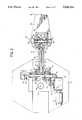
- FIG. 1is a perspective view of a mobile base and the lifting device according to the present invention showing the lifting device in its lower extended position.
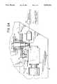
- FIG. 2is a top plan view of the lifting device and mobile base shown in FIG. 1, showing the lifting device in its lower extended position, the view taken cross-sectionally through the first arm assembly of the lifting device along line 2--2 of FIG. 3.
- FIG. 2Ais a partial top plan view of a second embodiment of the lifting device shown in FIG. 2, showing the motor, worm, worm gear, inclination sensor, angle encoder and control circuit to adjust the base mounted shaft, which otherwise is fixed, so as to in turn adjust the platform.
- the platformmay be adjusted so as to maintain a level orientation when the mobile base traverses an inclined surface.
- FIG. 3is a side elevational view of the lifting device and the upper portion of the mobile base upon which it is pivotally installed, including a cross-sectional view of the second arm assembly taken along line 3--3 of FIG. 2.
- FIG. 3Ais a partial side elevational view of the second embodiment of the lifting device shown in FIG. 2A.
- FIG. 4is a cross-sectional view of the yoke connected at the lower termination of the second arm assembly, taken along line 4--4 of FIG. 3.
- FIG. 5is a side elevational view of the mobile base and lifting device shown in FIG. 1, illustrating partially in phantom, several positions of the lifting device, including the home position wherein the platform is positioned over the mobile base and the lower extended position in which the platform is positioned at its lowermost position forward of the mobile base.
- FIG. 6is a top plan view of the mobile base and lifting device.
- FIGS. 7A through 7Fare each side elevational views of the lifting device showing various positions between and including the home position wherein the platform is positioned over the mobile base (FIGS. 7A) through the platform's lowermost extended position (FIG. 7F).
- FIG. 7Eshows the angular relationship of the first and second arm assemblies when the minimum angular distance between the two arm assemblies is encountered.
- a lifting device 20is preferably mounted to a rotatable turret 22 of a mobile base 24.
- the mobile base shown in FIG. 1corresponds to applicant's K2ATM Mobile Base as illustrated in assignee's U.S. Pat. No. 4,657,104, which is hereby incorporated by reference.
- the lifting deviceincludes a first arm assembly 26, a second arm assembly 28 and a platform 30 having a flat planar surface for supporting objects to be placed thereon (objects not shown).
- the lifting devicecan be angularly displaced throughout a continuum of positions.
- One such positionis a home position that is shown in FIGS. 5 and 7A, wherein the platform is positioned above the mobile base.
- Another position at the maximum clockwise displacement of arm assembly 26is a lower extended position. This position is also shown in FIGS. 5 and 7F, wherein the platform extends away from the mobile base and at its lowermost position with respect to the mobile base.
- the platform at these two end positions as well as all intermediate positions including those shown in FIGS. 7B-7Emaintains a fixed angular orientation with respect to the mobile base and thus to the surface 32 of which the mobile base is positioned.
- the fixed angular orientationoccurs as a result of surface 93 of yoke 92 contacting surface 97 of yoke 98.
- the lifting device 20incorporates an electric motor 34 which drives a worm gear reduction unit 36 so as to yield a fifty to one (50:1) reduction ratio at output shaft 38.
- Both motor 34 and reduction unit 36are affixed to mounting support 40 which in turn is attached to mounting plate 43.
- Mounting plate 43is mounted to base plate 42 by turret shaft 46 so as to be pivotable about axis 44.
- the entire lifting device 20 in association with turret 22can be turned by rotation of turret shaft 46 as shown by directional arrows 47 and 48.
- output shaft 38 of gear reducer 36terminates with a spur pinion gear 50 which drives a larger spur gear 52 in a reduction ratio of approximately four to one (4:1).
- Spur gear 52in turn is attached to a collar 54 which is rotatable about shaft 56 mounted to mounting support 40 by locking collet 76.
- Collar 54in turn is secured to a yoke 58 which at its other end, is attached to a second collar 60 which is also free to rotate about shaft 56.
- cams 62 and 64which in turn respectively control operation of limit switches 66 and 68.
- the camsare positioned on collar 60 so as to cause limit switch 66 to change state (open to close) when the first arm assembly reaches the home position shown in FIG. 7A, and for limit switch 68 to change state when the lower extended position shown in FIG. 7F is reached; thereby preventing the first arm assembly from making contact with base plate 42.
- An encoder 70is also attached to the terminating end of collar 60 so as to generate information concerning the angular position of collar 60 and thus arm assembly 26. Such information can be used by control apparatus (not shown) which instructs operation of motor 34 and thus the angular position of arm 26.
- yoke 58is attached to the arm 72 of first arm assembly 26, and thus rotation of yoke 58 causes a similar rotation of arm assembly 26 as shown in FIGS. 7A-7F.
- a bevel gear 78is rigidly mounted to shaft 56 by means of key 79. This gear mates with a bevel pinion 80 which in turn is secured at one end to rotatable shaft 82 by means of key 85. Shaft 82 is concentrically positioned within arm 72 by means of bearings 84. It is therefore readily seen that angular rotation of first arm assembly 26 as shown in FIGS. 7A-7F causes bevel pinion 80 to rotate about axis 83 as it moves about the periphery of gear 78.
- shaft 82terminates in a second bevel pinion 86 mounted thereto by key 87.
- Bevel pinion 86in turn mates with an idler bevel gear 88 mounted to idler shaft 90 by means of key 89.
- Shaft 90is rotatably mounted to yokes 92 and 98 by means of bearing 95.
- FIGS. 2 and 3also show that yoke 92 is fixedly attached to arm 72 so that angular rotation of first arm assembly 26 causes the yoke housing to be similarly rotated about shaft 56. Such action is seen in FIGS. 7A-7F.
- a second arm assembly 94includes arm 96 which pivotally depends from yoke 92. Arm 96 terminates at its upper end with yoke 98 as seen in FIGS. 2 and 3.
- shaft 102Rotatably mounted within arm 96 and forming part of second arm assembly 94 is shaft 102 terminating at its upper end with a bevel pinion 104 mounted thereto by key 105.
- Bearings 100allow shaft 102 to freely rotate about axis 103.
- This bevel pinionmates with idler bevel gear 88 so that rotation of bevel gear 86 imparts rotational movement to idler bevel gear 88, which in turn imparts rotation to bevel gear 104 and thus shaft 102.
- shaft 102terminates with a second bevel pinion 106 by means of key 107.
- arm 96is mounted to a yoke 108.
- bevel pinion 106meshes with bevel gear 110 which in turn is mounted to shaft 112 by means of key 117.
- Shaft 112is rotatably connected to yoke 108 by means of bearings 114.
- the platform 30is secured to hubs 115 by means of mounting screws 116. Hubs 115 are secured to shaft 112 by keys 118 so that rotation of bevel gear 110 imparts angular displacement to hubs 115 and hence to platform 30 with respect to yoke 108.
- the bevel gears located at each end of the shafts 82 and 102have the same number of teeth and consequently, any given angular rotation of first shaft 82 imparts a similar angular rotation to second rotatable shaft 102.
- the number of teeth associated with idler bevel gear 88is immaterial with regard to this similar angular rotation of the shafts 82 and 102.
- the number of teeth on bevel gear 110equals the number of teeth on fixed bevel gear 78.
- the number of teeth on bevel gear 110could be adjusted so as to counteract the increase or decrease of rotation of shaft 102 with regard to shaft 82, so as to maintain a one to one (1:1) relationship between angular movement of bevel gear 110 with respect to angular movement of first arm assembly 26 and thus to bevel gear 78.
- the second arm assembly 94will maintain a perpendicular orientation with respect to the surface 32 upon which the mobile base is placed unless yoke 98 mechanically contacts yoke 92 as shown in FIGS. 7A-7E at surfaces 93 and 97 respectively.
- the angle subtended by the first and second arm assemblies when in contact with each otheris 60 degrees and thus the first arm assembly can be rotated 150 degrees beyond the base plate datum 111 as shown in FIG. 7E and still be in contact with the second arm assembly. With this angular relationship, the second arm assembly undergoes a similar angular movement as the first arm assembly as shown in FIGS. 7A-7E.
- platform 30although the second arm assembly during such times undergoes an angular movement equal to that of the first arm assembly, platform 30 nevertheless remains parallel with the surface upon which the mobile base is placed due to the fact that bevel pinion 80 continues to rotate about the bevel gear 78 throughout the complete angular movement of the first arm assembly. In this manner, the platform 30 is able to not only maintain a parallel relationship with regard to the surface upon which the mobile base is placed, but can also be extended outward from the mobile base as illustrated in FIGS. 7A-7F, as well as in FIGS. 1, 5 and 6.
- FIGS. 2A and 3Ashow a second embodiment of the present invention wherein platform 30 can be angularly displaced or reoriented with respect to surface 32.
- shaft 56is no longer fixed with respect to base plate 43 via locking collet 76, but rather can be angularly rotated by means of motor 35 and associated worm 37 and gear 45.
- the motormay be driven as a result of information concerning the inclination of surface 32 upon which the mobile base is placed by means of a damped pendulum inclination sensor 39 associated with an angle encoder and control circuit 41.
- this informationcan be used to drive motor 35 which in turn drives worm 37 and thus gear 45 which controls the angular displacement of shaft 56 and associated gear 78 so as to cause a compensating angular movement to platform 30; thereby maintaining platform 30 level to the earth rather than parallel to the surface upon which the mobile base is traversing.
- Motor 35 and associated worm 37 and gear 45can also be used to adjust the angular position of platform 30 while the arm assemblies are stationary so as to facilitate loading and unloading of objects onto and off of platform 30 such as when loading and unloading pallets and the like.
- the lifting devicenot only can maintain a parallel orientation with respect to the surface upon which the mobile base is placed, but alternatively can adjust that position when it is desired to do so.
Landscapes
- Engineering & Computer Science (AREA)
- Robotics (AREA)
- Mechanical Engineering (AREA)
- Jib Cranes (AREA)
Abstract
Description
Claims (15)
Priority Applications (1)
| Application Number | Priority Date | Filing Date | Title |
|---|---|---|---|
| US07/609,016US5046914A (en) | 1988-07-12 | 1990-10-23 | Parallel lifting device |
Applications Claiming Priority (2)
| Application Number | Priority Date | Filing Date | Title |
|---|---|---|---|
| US21809488A | 1988-07-12 | 1988-07-12 | |
| US07/609,016US5046914A (en) | 1988-07-12 | 1990-10-23 | Parallel lifting device |
Related Parent Applications (1)
| Application Number | Title | Priority Date | Filing Date |
|---|---|---|---|
| US21809488AContinuation | 1988-07-12 | 1988-07-12 |
Publications (1)
| Publication Number | Publication Date |
|---|---|
| US5046914Atrue US5046914A (en) | 1991-09-10 |
Family
ID=26912559
Family Applications (1)
| Application Number | Title | Priority Date | Filing Date |
|---|---|---|---|
| US07/609,016Expired - Fee RelatedUS5046914A (en) | 1988-07-12 | 1990-10-23 | Parallel lifting device |
Country Status (1)
| Country | Link |
|---|---|
| US (1) | US5046914A (en) |
Cited By (34)
| Publication number | Priority date | Publication date | Assignee | Title |
|---|---|---|---|---|
| US5609216A (en)* | 1995-03-01 | 1997-03-11 | Cybermotion, Inc. | Mobile base having leg assemblies with two wheels |
| US5720077A (en)* | 1994-05-30 | 1998-02-24 | Minolta Co., Ltd. | Running robot carrying out prescribed work using working member and method of working using the same |
| US5731678A (en)* | 1996-07-15 | 1998-03-24 | Semitool, Inc. | Processing head for semiconductor processing machines |
| GB2345051A (en)* | 1998-12-22 | 2000-06-28 | Maria Varvarides | Robot Device |
| US6276633B1 (en)* | 1999-03-25 | 2001-08-21 | Eurocopter | Convertible aircraft with tilting rotors |
| US6547217B1 (en) | 2000-09-13 | 2003-04-15 | Pcc Superior Fabrication | Variable reach lift arm |
| US7063498B1 (en)* | 2003-12-03 | 2006-06-20 | Owens-Brockway Glass Container Inc. | Method of and apparatus for transferring articles from a first position to a second position |
| US7192236B1 (en)* | 1999-03-02 | 2007-03-20 | Westfalia-Wst-Systemtechnik Gmbh & Co. Kg | Shelf stacking machine |
| EP1916070A1 (en)* | 2006-10-28 | 2008-04-30 | Diehl BGT Defence GmbH & Co.KG | Controllable mobile ground robot |
| US20080217993A1 (en)* | 2006-11-13 | 2008-09-11 | Jacobsen Stephen C | Conformable track assembly for a robotic crawler |
| US20090214324A1 (en)* | 2008-02-21 | 2009-08-27 | Grinnell Charles M | Adaptable container handling system |
| US20110048158A1 (en)* | 2008-04-09 | 2011-03-03 | Aldebaran Robotics | Motorized joint with two pivot connections and humanoid robot which implements the joint |
| US8002716B2 (en) | 2007-05-07 | 2011-08-23 | Raytheon Company | Method for manufacturing a complex structure |
| US8042630B2 (en) | 2006-11-13 | 2011-10-25 | Raytheon Company | Serpentine robotic crawler |
| US20120085191A1 (en)* | 2010-10-11 | 2012-04-12 | Hon Hai Precision Industry Co., Ltd. | Robot arm assembly |
| US8185241B2 (en) | 2006-11-13 | 2012-05-22 | Raytheon Company | Tracked robotic crawler having a moveable arm |
| US8317555B2 (en) | 2009-06-11 | 2012-11-27 | Raytheon Company | Amphibious robotic crawler |
| US8392036B2 (en) | 2009-01-08 | 2013-03-05 | Raytheon Company | Point and go navigation system and method |
| US8393422B1 (en) | 2012-05-25 | 2013-03-12 | Raytheon Company | Serpentine robotic crawler |
| US8571711B2 (en) | 2007-07-10 | 2013-10-29 | Raytheon Company | Modular robotic crawler |
| US8676425B2 (en) | 2011-11-02 | 2014-03-18 | Harvest Automation, Inc. | Methods and systems for maintenance and other processing of container-grown plants using autonomous mobile robots |
| US8935014B2 (en) | 2009-06-11 | 2015-01-13 | Sarcos, Lc | Method and system for deploying a surveillance network |
| US8937410B2 (en) | 2012-01-17 | 2015-01-20 | Harvest Automation, Inc. | Emergency stop method and system for autonomous mobile robots |
| US9031698B2 (en) | 2012-10-31 | 2015-05-12 | Sarcos Lc | Serpentine robotic crawler |
| US9147173B2 (en) | 2011-10-31 | 2015-09-29 | Harvest Automation, Inc. | Methods and systems for automated transportation of items between variable endpoints |
| US20160045055A1 (en)* | 2014-08-16 | 2016-02-18 | Tony Kahn Vong | Autonomous Chef |
| US9409292B2 (en) | 2013-09-13 | 2016-08-09 | Sarcos Lc | Serpentine robotic crawler for performing dexterous operations |
| US9566711B2 (en) | 2014-03-04 | 2017-02-14 | Sarcos Lc | Coordinated robotic control |
| US20180199764A1 (en)* | 2014-08-16 | 2018-07-19 | Tony Kahn Vong | Robotic Device Coupled with Material Inputting, Material Holding and Washing Device |
| US10071303B2 (en) | 2015-08-26 | 2018-09-11 | Malibu Innovations, LLC | Mobilized cooler device with fork hanger assembly |
| US10807659B2 (en) | 2016-05-27 | 2020-10-20 | Joseph L. Pikulski | Motorized platforms |
| US20220250231A1 (en)* | 2010-04-09 | 2022-08-11 | Willow Garage, Llc | Humanoid robotics system and methods |
| US20230404341A1 (en)* | 2020-11-06 | 2023-12-21 | Dyson Technology Limited | Robotic surface treating system |
| US12311550B2 (en) | 2020-12-31 | 2025-05-27 | Sarcos Corp. | Smart control system for a robotic device |
Citations (13)
| Publication number | Priority date | Publication date | Assignee | Title |
|---|---|---|---|---|
| US3937339A (en)* | 1971-10-29 | 1976-02-10 | Koehring Company | Vehicle having transverse leveling means |
| JPS5273463A (en)* | 1975-12-13 | 1977-06-20 | Kawasaki Heavy Ind Ltd | Robot for industrial use |
| US4065001A (en)* | 1976-06-15 | 1977-12-27 | Shiroyama Kogyo Co., Ltd. | Manipulator |
| US4396344A (en)* | 1979-10-12 | 1983-08-02 | Hitachi, Ltd. | Industrial robot of the articulated type |
| US4531884A (en)* | 1982-11-15 | 1985-07-30 | Russell Richard H | Automated machine |
| US4586868A (en)* | 1982-10-20 | 1986-05-06 | Fanuc, Ltd. | Wrist mechanism of an industrial robot |
| US4601635A (en)* | 1982-05-14 | 1986-07-22 | Toyoda Koki Kabushiki Kaisha | Multilink-type robot |
| US4606695A (en)* | 1984-05-18 | 1986-08-19 | Kurt Manufacturing Company, Inc. | Multiple axis robot arm |
| US4632630A (en)* | 1983-05-03 | 1986-12-30 | Koehring Company | Forklift attachment |
| US4645408A (en)* | 1985-09-27 | 1987-02-24 | Mizuno Tekko Kabushiki Kaisha | Uncontrolled angular displacement compensating device for industrial robot |
| US4662814A (en)* | 1983-10-05 | 1987-05-05 | Hitachi, Ltd. | Manipulator |
| US4685861A (en)* | 1984-10-30 | 1987-08-11 | Michael Madock | Continuous shaft-driven industrial robot |
| US4704065A (en)* | 1984-08-31 | 1987-11-03 | Asea Ab | Wrist for an industrial robot |
- 1990
- 1990-10-23USUS07/609,016patent/US5046914A/ennot_activeExpired - Fee Related
Patent Citations (13)
| Publication number | Priority date | Publication date | Assignee | Title |
|---|---|---|---|---|
| US3937339A (en)* | 1971-10-29 | 1976-02-10 | Koehring Company | Vehicle having transverse leveling means |
| JPS5273463A (en)* | 1975-12-13 | 1977-06-20 | Kawasaki Heavy Ind Ltd | Robot for industrial use |
| US4065001A (en)* | 1976-06-15 | 1977-12-27 | Shiroyama Kogyo Co., Ltd. | Manipulator |
| US4396344A (en)* | 1979-10-12 | 1983-08-02 | Hitachi, Ltd. | Industrial robot of the articulated type |
| US4601635A (en)* | 1982-05-14 | 1986-07-22 | Toyoda Koki Kabushiki Kaisha | Multilink-type robot |
| US4586868A (en)* | 1982-10-20 | 1986-05-06 | Fanuc, Ltd. | Wrist mechanism of an industrial robot |
| US4531884A (en)* | 1982-11-15 | 1985-07-30 | Russell Richard H | Automated machine |
| US4632630A (en)* | 1983-05-03 | 1986-12-30 | Koehring Company | Forklift attachment |
| US4662814A (en)* | 1983-10-05 | 1987-05-05 | Hitachi, Ltd. | Manipulator |
| US4606695A (en)* | 1984-05-18 | 1986-08-19 | Kurt Manufacturing Company, Inc. | Multiple axis robot arm |
| US4704065A (en)* | 1984-08-31 | 1987-11-03 | Asea Ab | Wrist for an industrial robot |
| US4685861A (en)* | 1984-10-30 | 1987-08-11 | Michael Madock | Continuous shaft-driven industrial robot |
| US4645408A (en)* | 1985-09-27 | 1987-02-24 | Mizuno Tekko Kabushiki Kaisha | Uncontrolled angular displacement compensating device for industrial robot |
Cited By (47)
| Publication number | Priority date | Publication date | Assignee | Title |
|---|---|---|---|---|
| US5720077A (en)* | 1994-05-30 | 1998-02-24 | Minolta Co., Ltd. | Running robot carrying out prescribed work using working member and method of working using the same |
| US5609216A (en)* | 1995-03-01 | 1997-03-11 | Cybermotion, Inc. | Mobile base having leg assemblies with two wheels |
| US5731678A (en)* | 1996-07-15 | 1998-03-24 | Semitool, Inc. | Processing head for semiconductor processing machines |
| GB2345051A (en)* | 1998-12-22 | 2000-06-28 | Maria Varvarides | Robot Device |
| US7192236B1 (en)* | 1999-03-02 | 2007-03-20 | Westfalia-Wst-Systemtechnik Gmbh & Co. Kg | Shelf stacking machine |
| US6276633B1 (en)* | 1999-03-25 | 2001-08-21 | Eurocopter | Convertible aircraft with tilting rotors |
| US6547217B1 (en) | 2000-09-13 | 2003-04-15 | Pcc Superior Fabrication | Variable reach lift arm |
| US7063498B1 (en)* | 2003-12-03 | 2006-06-20 | Owens-Brockway Glass Container Inc. | Method of and apparatus for transferring articles from a first position to a second position |
| EP1916070A1 (en)* | 2006-10-28 | 2008-04-30 | Diehl BGT Defence GmbH & Co.KG | Controllable mobile ground robot |
| US20080217993A1 (en)* | 2006-11-13 | 2008-09-11 | Jacobsen Stephen C | Conformable track assembly for a robotic crawler |
| US8185241B2 (en) | 2006-11-13 | 2012-05-22 | Raytheon Company | Tracked robotic crawler having a moveable arm |
| US8002365B2 (en) | 2006-11-13 | 2011-08-23 | Raytheon Company | Conformable track assembly for a robotic crawler |
| US8042630B2 (en) | 2006-11-13 | 2011-10-25 | Raytheon Company | Serpentine robotic crawler |
| US8205695B2 (en) | 2006-11-13 | 2012-06-26 | Raytheon Company | Conformable track assembly for a robotic crawler |
| US8434208B2 (en) | 2007-05-07 | 2013-05-07 | Raytheon Company | Two-dimensional layout for use in a complex structure |
| US8002716B2 (en) | 2007-05-07 | 2011-08-23 | Raytheon Company | Method for manufacturing a complex structure |
| US8571711B2 (en) | 2007-07-10 | 2013-10-29 | Raytheon Company | Modular robotic crawler |
| WO2009105211A3 (en)* | 2008-02-21 | 2009-12-30 | Q Robotics, Llc | Adaptable container handling system |
| EP2244910A4 (en)* | 2008-02-21 | 2013-05-15 | Harvest Automation Inc | Adaptable container handling system |
| US20090214324A1 (en)* | 2008-02-21 | 2009-08-27 | Grinnell Charles M | Adaptable container handling system |
| US8915692B2 (en) | 2008-02-21 | 2014-12-23 | Harvest Automation, Inc. | Adaptable container handling system |
| US8997599B2 (en)* | 2008-04-09 | 2015-04-07 | Aldebaran Robotics | Motorized joint with two pivot connections and humanoid robot which implements the joint |
| US20110048158A1 (en)* | 2008-04-09 | 2011-03-03 | Aldebaran Robotics | Motorized joint with two pivot connections and humanoid robot which implements the joint |
| US8392036B2 (en) | 2009-01-08 | 2013-03-05 | Raytheon Company | Point and go navigation system and method |
| US8317555B2 (en) | 2009-06-11 | 2012-11-27 | Raytheon Company | Amphibious robotic crawler |
| US8935014B2 (en) | 2009-06-11 | 2015-01-13 | Sarcos, Lc | Method and system for deploying a surveillance network |
| US12403584B2 (en)* | 2010-04-09 | 2025-09-02 | Willow Garage, Llc | Humanoid robotics system and methods |
| US20220250231A1 (en)* | 2010-04-09 | 2022-08-11 | Willow Garage, Llc | Humanoid robotics system and methods |
| US8534153B2 (en)* | 2010-10-11 | 2013-09-17 | Hong Fu Jin Precision Industry (Shenzhen) Co., Ltd. | Robot arm assembly |
| US20120085191A1 (en)* | 2010-10-11 | 2012-04-12 | Hon Hai Precision Industry Co., Ltd. | Robot arm assembly |
| US9147173B2 (en) | 2011-10-31 | 2015-09-29 | Harvest Automation, Inc. | Methods and systems for automated transportation of items between variable endpoints |
| US9568917B2 (en) | 2011-10-31 | 2017-02-14 | Harvest Automation, Inc. | Methods and systems for automated transportation of items between variable endpoints |
| US8676425B2 (en) | 2011-11-02 | 2014-03-18 | Harvest Automation, Inc. | Methods and systems for maintenance and other processing of container-grown plants using autonomous mobile robots |
| US8937410B2 (en) | 2012-01-17 | 2015-01-20 | Harvest Automation, Inc. | Emergency stop method and system for autonomous mobile robots |
| US8393422B1 (en) | 2012-05-25 | 2013-03-12 | Raytheon Company | Serpentine robotic crawler |
| US9031698B2 (en) | 2012-10-31 | 2015-05-12 | Sarcos Lc | Serpentine robotic crawler |
| US9409292B2 (en) | 2013-09-13 | 2016-08-09 | Sarcos Lc | Serpentine robotic crawler for performing dexterous operations |
| US9566711B2 (en) | 2014-03-04 | 2017-02-14 | Sarcos Lc | Coordinated robotic control |
| US20180199764A1 (en)* | 2014-08-16 | 2018-07-19 | Tony Kahn Vong | Robotic Device Coupled with Material Inputting, Material Holding and Washing Device |
| US10722078B2 (en)* | 2014-08-16 | 2020-07-28 | Tony Kahn Vong | Robotic cooking device having rotatable and tiltable arms that enabling transference of food between food processing units that are attached at ends of the arms |
| US9955823B2 (en)* | 2014-08-16 | 2018-05-01 | Tony Kahn Vong | Autonomous chef |
| US20160045055A1 (en)* | 2014-08-16 | 2016-02-18 | Tony Kahn Vong | Autonomous Chef |
| US10071303B2 (en) | 2015-08-26 | 2018-09-11 | Malibu Innovations, LLC | Mobilized cooler device with fork hanger assembly |
| US10814211B2 (en) | 2015-08-26 | 2020-10-27 | Joseph Pikulski | Mobilized platforms |
| US10807659B2 (en) | 2016-05-27 | 2020-10-20 | Joseph L. Pikulski | Motorized platforms |
| US20230404341A1 (en)* | 2020-11-06 | 2023-12-21 | Dyson Technology Limited | Robotic surface treating system |
| US12311550B2 (en) | 2020-12-31 | 2025-05-27 | Sarcos Corp. | Smart control system for a robotic device |
Similar Documents
| Publication | Publication Date | Title |
|---|---|---|
| US5046914A (en) | Parallel lifting device | |
| KR0168696B1 (en) | Industrial robot for workpiece transfer between presses of press line | |
| US4661040A (en) | Manipulator robot, more particularly for transferring sheet metal elements from a pressing station to the next pressing station of a pressing line | |
| US5222409A (en) | Industrial robot arms | |
| AU725673B2 (en) | Invalid hoists | |
| JPS6312752B2 (en) | ||
| JPH07100309B2 (en) | Leg mechanism that can be used as an arm for a walking robot | |
| US5771748A (en) | Highly stable Z axis drive | |
| WO1989007082A1 (en) | Cargo conveyor system | |
| JP3307458B2 (en) | Articulated robot | |
| KR101193761B1 (en) | Articulated robot | |
| JPH07100774A (en) | Multiped working robot equipped with leg which can be used as arm | |
| GB2126559A (en) | Manipulator apparatus | |
| US20060207377A1 (en) | Actuating device, particularly for an articulated arm | |
| CA1154283A (en) | Mid-point dwell linkage system | |
| JPH0679461A (en) | Automatic welding equipment | |
| JPH0890463A (en) | Horizontal articulated robot | |
| JP7723541B2 (en) | Mobile | |
| JPS6334870Y2 (en) | ||
| JPH07124877A (en) | Master-slave type manipulator slave arm | |
| CN223115218U (en) | Automatic tilting mechanism of intelligent manipulator major diameter dish class | |
| JP3310477B2 (en) | Rice transplanter | |
| JP3657101B2 (en) | Wagon with auxiliary power mechanism | |
| JPH045571Y2 (en) | ||
| JPH08216062A (en) | Workbench |
Legal Events
| Date | Code | Title | Description |
|---|---|---|---|
| AS | Assignment | Owner name:CRESTAR BANK, VIRGINIA Free format text:ASSIGNMENT OF ASSIGNORS INTEREST;ASSIGNOR:CYBERMOTION, INC. A CORPORATION OF VIRGINIA;REEL/FRAME:007080/0292 Effective date:19940714 | |
| FEPP | Fee payment procedure | Free format text:PAYOR NUMBER ASSIGNED (ORIGINAL EVENT CODE: ASPN); ENTITY STATUS OF PATENT OWNER: SMALL ENTITY | |
| FPAY | Fee payment | Year of fee payment:4 | |
| AS | Assignment | Owner name:VEDCORP. L.C., VIRGINIA Free format text:SECURITY INTEREST;ASSIGNOR:CYBERMOTION, INC.;REEL/FRAME:007439/0120 Effective date:19950314 | |
| AS | Assignment | Owner name:KENNEDY, KENNTH F., VIRGINIA Free format text:SECURITY AGREEMENT;ASSIGNOR:CYBERMOTION, INC.;REEL/FRAME:007881/0327 Effective date:19950301 Owner name:MASON, W. F., JR., ESQUIRE, VIRGINIA Free format text:SECURITY AGREEMENT;ASSIGNOR:CYBERMOTION, INC.;REEL/FRAME:007881/0327 Effective date:19950301 | |
| FPAY | Fee payment | Year of fee payment:8 | |
| REMI | Maintenance fee reminder mailed | ||
| LAPS | Lapse for failure to pay maintenance fees | ||
| STCH | Information on status: patent discontinuation | Free format text:PATENT EXPIRED DUE TO NONPAYMENT OF MAINTENANCE FEES UNDER 37 CFR 1.362 | |
| FP | Lapsed due to failure to pay maintenance fee | Effective date:20030910 |