US5046497A - Structure for coupling a guidewire and a catheter - Google Patents
Structure for coupling a guidewire and a catheterDownload PDFInfo
- Publication number
- US5046497A US5046497AUS07/286,480US28648088AUS5046497AUS 5046497 AUS5046497 AUS 5046497AUS 28648088 AUS28648088 AUS 28648088AUS 5046497 AUS5046497 AUS 5046497A
- Authority
- US
- United States
- Prior art keywords
- guidewire
- fingers
- vessel
- catheter
- devices
- Prior art date
- Legal status (The legal status is an assumption and is not a legal conclusion. Google has not performed a legal analysis and makes no representation as to the accuracy of the status listed.)
- Expired - Lifetime
Links
Images


Classifications
- A—HUMAN NECESSITIES
- A61—MEDICAL OR VETERINARY SCIENCE; HYGIENE
- A61M—DEVICES FOR INTRODUCING MEDIA INTO, OR ONTO, THE BODY; DEVICES FOR TRANSDUCING BODY MEDIA OR FOR TAKING MEDIA FROM THE BODY; DEVICES FOR PRODUCING OR ENDING SLEEP OR STUPOR
- A61M25/00—Catheters; Hollow probes
- A61M25/01—Introducing, guiding, advancing, emplacing or holding catheters
- A61M25/0169—Exchanging a catheter while keeping the guidewire in place
- A—HUMAN NECESSITIES
- A61—MEDICAL OR VETERINARY SCIENCE; HYGIENE
- A61B—DIAGNOSIS; SURGERY; IDENTIFICATION
- A61B5/00—Measuring for diagnostic purposes; Identification of persons
- A61B5/145—Measuring characteristics of blood in vivo, e.g. gas concentration or pH-value ; Measuring characteristics of body fluids or tissues, e.g. interstitial fluid or cerebral tissue
- A61B5/14539—Measuring characteristics of blood in vivo, e.g. gas concentration or pH-value ; Measuring characteristics of body fluids or tissues, e.g. interstitial fluid or cerebral tissue for measuring pH
- A—HUMAN NECESSITIES
- A61—MEDICAL OR VETERINARY SCIENCE; HYGIENE
- A61B—DIAGNOSIS; SURGERY; IDENTIFICATION
- A61B5/00—Measuring for diagnostic purposes; Identification of persons
- A61B5/02—Detecting, measuring or recording for evaluating the cardiovascular system, e.g. pulse, heart rate, blood pressure or blood flow
- A61B5/021—Measuring pressure in heart or blood vessels
- A61B5/0215—Measuring pressure in heart or blood vessels by means inserted into the body
- A—HUMAN NECESSITIES
- A61—MEDICAL OR VETERINARY SCIENCE; HYGIENE
- A61B—DIAGNOSIS; SURGERY; IDENTIFICATION
- A61B8/00—Diagnosis using ultrasonic, sonic or infrasonic waves
- A61B8/12—Diagnosis using ultrasonic, sonic or infrasonic waves in body cavities or body tracts, e.g. by using catheters
- A—HUMAN NECESSITIES
- A61—MEDICAL OR VETERINARY SCIENCE; HYGIENE
- A61M—DEVICES FOR INTRODUCING MEDIA INTO, OR ONTO, THE BODY; DEVICES FOR TRANSDUCING BODY MEDIA OR FOR TAKING MEDIA FROM THE BODY; DEVICES FOR PRODUCING OR ENDING SLEEP OR STUPOR
- A61M25/00—Catheters; Hollow probes
- A61M25/0021—Catheters; Hollow probes characterised by the form of the tubing
- A61M25/0023—Catheters; Hollow probes characterised by the form of the tubing by the form of the lumen, e.g. cross-section, variable diameter
- A61M25/0026—Multi-lumen catheters with stationary elements
- A61M2025/0037—Multi-lumen catheters with stationary elements characterized by lumina being arranged side-by-side
- A—HUMAN NECESSITIES
- A61—MEDICAL OR VETERINARY SCIENCE; HYGIENE
- A61M—DEVICES FOR INTRODUCING MEDIA INTO, OR ONTO, THE BODY; DEVICES FOR TRANSDUCING BODY MEDIA OR FOR TAKING MEDIA FROM THE BODY; DEVICES FOR PRODUCING OR ENDING SLEEP OR STUPOR
- A61M25/00—Catheters; Hollow probes
- A61M25/01—Introducing, guiding, advancing, emplacing or holding catheters
- A61M2025/0177—Introducing, guiding, advancing, emplacing or holding catheters having external means for receiving guide wires, wires or stiffening members, e.g. loops, clamps or lateral tubes
- A—HUMAN NECESSITIES
- A61—MEDICAL OR VETERINARY SCIENCE; HYGIENE
- A61M—DEVICES FOR INTRODUCING MEDIA INTO, OR ONTO, THE BODY; DEVICES FOR TRANSDUCING BODY MEDIA OR FOR TAKING MEDIA FROM THE BODY; DEVICES FOR PRODUCING OR ENDING SLEEP OR STUPOR
- A61M25/00—Catheters; Hollow probes
- A61M25/01—Introducing, guiding, advancing, emplacing or holding catheters
- A61M2025/0183—Rapid exchange or monorail catheters
- A—HUMAN NECESSITIES
- A61—MEDICAL OR VETERINARY SCIENCE; HYGIENE
- A61M—DEVICES FOR INTRODUCING MEDIA INTO, OR ONTO, THE BODY; DEVICES FOR TRANSDUCING BODY MEDIA OR FOR TAKING MEDIA FROM THE BODY; DEVICES FOR PRODUCING OR ENDING SLEEP OR STUPOR
- A61M25/00—Catheters; Hollow probes
- A61M25/0021—Catheters; Hollow probes characterised by the form of the tubing
- A61M25/0023—Catheters; Hollow probes characterised by the form of the tubing by the form of the lumen, e.g. cross-section, variable diameter
- A61M25/0026—Multi-lumen catheters with stationary elements
- A61M25/003—Multi-lumen catheters with stationary elements characterized by features relating to least one lumen located at the distal part of the catheter, e.g. filters, plugs or valves
- A—HUMAN NECESSITIES
- A61—MEDICAL OR VETERINARY SCIENCE; HYGIENE
- A61M—DEVICES FOR INTRODUCING MEDIA INTO, OR ONTO, THE BODY; DEVICES FOR TRANSDUCING BODY MEDIA OR FOR TAKING MEDIA FROM THE BODY; DEVICES FOR PRODUCING OR ENDING SLEEP OR STUPOR
- A61M25/00—Catheters; Hollow probes
- A61M25/0067—Catheters; Hollow probes characterised by the distal end, e.g. tips
- A61M25/0068—Static characteristics of the catheter tip, e.g. shape, atraumatic tip, curved tip or tip structure
- A—HUMAN NECESSITIES
- A61—MEDICAL OR VETERINARY SCIENCE; HYGIENE
- A61M—DEVICES FOR INTRODUCING MEDIA INTO, OR ONTO, THE BODY; DEVICES FOR TRANSDUCING BODY MEDIA OR FOR TAKING MEDIA FROM THE BODY; DEVICES FOR PRODUCING OR ENDING SLEEP OR STUPOR
- A61M25/00—Catheters; Hollow probes
- A61M25/0067—Catheters; Hollow probes characterised by the distal end, e.g. tips
- A61M25/0082—Catheter tip comprising a tool
Definitions
- the first deviceAfter connecting the first device to the guidewire, the first device is inserted into the region of the vessel of interest with the coupling structure slidably engaging the guidewire.
- the cathetertrails the body into the vessel and is generally longitudinally aligned and juxtaposed relative to the guidewire.
- a second deviceis connected to the guidewire and inserted into the vessel region in a fashion similar to the first device.
- the first and second devicesare positioned along the guidewire in the region of interest with the respective catheters radially spaced about the guidewire.
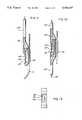
- FIGS. 16-17still another alternative embodiment is illustrated which contains only a single proximal pressure sensor 128.
- a connection structure 144is coupled to the guidewire 10 distal to the angioplasty device 114.
- the connection structure 144is interconnected to the proximal pressure sensor 128 via a link or tether 146.
- the tether 146has no requirement for a reference pressure lumen.
- the connection structure 144(FIG. 17) omits the tubular journal 142 (FIG. 15) such that the connection structure 144 simply abuts the angioplasty device 114.
- the cross-sectional dimension of the devices 112, 114may be tapered from the connection structure 144 to the pressure sensor 128.
Landscapes
- Health & Medical Sciences (AREA)
- Life Sciences & Earth Sciences (AREA)
- Public Health (AREA)
- Biophysics (AREA)
- Physics & Mathematics (AREA)
- Engineering & Computer Science (AREA)
- Biomedical Technology (AREA)
- Heart & Thoracic Surgery (AREA)
- Veterinary Medicine (AREA)
- Animal Behavior & Ethology (AREA)
- General Health & Medical Sciences (AREA)
- Anesthesiology (AREA)
- Hematology (AREA)
- Pulmonology (AREA)
- Optics & Photonics (AREA)
- Pathology (AREA)
- Medical Informatics (AREA)
- Molecular Biology (AREA)
- Surgery (AREA)
- Media Introduction/Drainage Providing Device (AREA)
Abstract
Description
Claims (17)
Priority Applications (1)
| Application Number | Priority Date | Filing Date | Title |
|---|---|---|---|
| US07/286,480US5046497A (en) | 1986-11-14 | 1988-12-19 | Structure for coupling a guidewire and a catheter |
Applications Claiming Priority (3)
| Application Number | Priority Date | Filing Date | Title |
|---|---|---|---|
| US06/931,273US4771782A (en) | 1986-11-14 | 1986-11-14 | Method and assembly for introducing multiple catheters into a biological vessel |
| US07/119,616US4850358A (en) | 1986-11-14 | 1987-11-12 | Method and assembly for introducing multiple devices into a biological vessel |
| US07/286,480US5046497A (en) | 1986-11-14 | 1988-12-19 | Structure for coupling a guidewire and a catheter |
Related Parent Applications (1)
| Application Number | Title | Priority Date | Filing Date |
|---|---|---|---|
| US07/119,616ContinuationUS4850358A (en) | 1986-11-14 | 1987-11-12 | Method and assembly for introducing multiple devices into a biological vessel |
Publications (1)
| Publication Number | Publication Date |
|---|---|
| US5046497Atrue US5046497A (en) | 1991-09-10 |
Family
ID=27382339
Family Applications (1)
| Application Number | Title | Priority Date | Filing Date |
|---|---|---|---|
| US07/286,480Expired - LifetimeUS5046497A (en) | 1986-11-14 | 1988-12-19 | Structure for coupling a guidewire and a catheter |
Country Status (1)
| Country | Link |
|---|---|
| US (1) | US5046497A (en) |
Cited By (208)
| Publication number | Priority date | Publication date | Assignee | Title |
|---|---|---|---|---|
| DE9114603U1 (en)* | 1991-11-23 | 1992-08-06 | B. Braun Melsungen Ag, 3508 Melsungen | Catheter exchange device |
| US5267958A (en)* | 1992-03-30 | 1993-12-07 | Medtronic, Inc. | Exchange catheter having exterior guide wire loops |
| US5280786A (en)* | 1992-01-21 | 1994-01-25 | Fiberoptic Sensor Technologies, Inc. | Fiberoptic blood pressure and oxygenation sensor |
| US5281203A (en)* | 1991-07-05 | 1994-01-25 | Scimed Life Systems, Inc. | Guide wire and sheath for single operator exchange |
| US5357978A (en)* | 1993-01-12 | 1994-10-25 | Medtronic, Inc. | Rapid exchange guidewire loading attachment |
| US5383853A (en)* | 1992-11-12 | 1995-01-24 | Medtronic, Inc. | Rapid exchange catheter |
| US5388590A (en)* | 1993-07-28 | 1995-02-14 | Medtronic, Inc. | Catheter exchange device |
| US5438985A (en)* | 1993-01-25 | 1995-08-08 | Synectics Medical, Incorporated | Ambulatory recording of the presence and activity of substances in gastro-intestinal compartments |
| US5477860A (en)* | 1992-11-05 | 1995-12-26 | Synectics Medical, Inc. | Catheter for measuring respiration and respiratory effort |
| US5477854A (en)* | 1993-09-16 | 1995-12-26 | Synectics Medical, Inc. | System and method to monitor gastrointestinal Helicobacter pylori infection |
| US5479935A (en)* | 1993-10-21 | 1996-01-02 | Synectics Medical, Inc. | Ambulatory reflux monitoring system |
| US5484409A (en)* | 1989-08-25 | 1996-01-16 | Scimed Life Systems, Inc. | Intravascular catheter and method for use thereof |
| US5490837A (en)* | 1991-07-05 | 1996-02-13 | Scimed Life Systems, Inc. | Single operator exchange catheter having a distal catheter shaft section |
| WO1996007351A1 (en)* | 1994-09-02 | 1996-03-14 | Cardiometrics, Inc. | Ultra miniature pressure sensor and guidewire using the same and method |
| US5507289A (en)* | 1993-09-16 | 1996-04-16 | Synectics Medical, Inc. | System and method to diagnose bacterial growth |
| US5536250A (en)* | 1994-04-01 | 1996-07-16 | Localmed, Inc. | Perfusion shunt device and method |
| US5549556A (en)* | 1992-11-19 | 1996-08-27 | Medtronic, Inc. | Rapid exchange catheter with external wire lumen |
| US5551425A (en)* | 1993-05-13 | 1996-09-03 | Synectics Medical, Inc. | Potential difference and perfusion pressure catheter |
| US5562620A (en)* | 1994-04-01 | 1996-10-08 | Localmed, Inc. | Perfusion shunt device having non-distensible pouch for receiving angioplasty balloon |
| US5571086A (en)* | 1992-11-02 | 1996-11-05 | Localmed, Inc. | Method and apparatus for sequentially performing multiple intraluminal procedures |
| US5599306A (en)* | 1994-04-01 | 1997-02-04 | Localmed, Inc. | Method and apparatus for providing external perfusion lumens on balloon catheters |
| WO1997017888A1 (en)* | 1995-11-13 | 1997-05-22 | Localmed, Inc. | Guide catheter with sensing element |
| US5657759A (en)* | 1993-05-13 | 1997-08-19 | Synectics Medical, Incorporated | Measurement of gastric emptying and gastrointestinal output |
| US5690642A (en) | 1996-01-18 | 1997-11-25 | Cook Incorporated | Rapid exchange stent delivery balloon catheter |
| US5810741A (en)* | 1992-11-05 | 1998-09-22 | Synectics Medical Ab | Method of measuring respiration and respiratory effort using plural catheters |
| US5833625A (en)* | 1993-10-21 | 1998-11-10 | Synectics Medical Ab | Ambulatory reflux monitoring system |
| US5902331A (en)* | 1998-03-10 | 1999-05-11 | Medtronic, Inc. | Arrangement for implanting an endocardial cardiac lead |
| US5947927A (en)* | 1998-03-23 | 1999-09-07 | Scimed Life Systems, Inc. | Convertible catheter having a single proximal lumen |
| US5976107A (en)* | 1991-07-05 | 1999-11-02 | Scimed Life Systems. Inc. | Catheter having extendable guide wire lumen |
| US6132456A (en)* | 1998-03-10 | 2000-10-17 | Medtronic, Inc. | Arrangement for implanting an endocardial cardiac lead |
| US6155977A (en)* | 1999-05-13 | 2000-12-05 | Nowakowski; Bogdan | Method and apparatus for placement of a catheter |
| EP1013304A3 (en)* | 1998-12-18 | 2000-12-20 | Pacesetter AB | A device for guiding and positioning leads |
| US6312452B1 (en)* | 1998-01-23 | 2001-11-06 | Innercool Therapies, Inc. | Selective organ cooling catheter with guidewire apparatus and temperature-monitoring device |
| US6475231B2 (en) | 1998-03-24 | 2002-11-05 | Innercool Therapies, Inc. | Method and device for applications of selective organ cooling |
| US6482226B1 (en) | 1998-01-23 | 2002-11-19 | Innercool Therapies, Inc. | Selective organ hypothermia method and apparatus |
| US6491039B1 (en) | 1998-01-23 | 2002-12-10 | Innercool Therapies, Inc. | Medical procedure |
| US6533804B2 (en) | 1998-01-23 | 2003-03-18 | Innercool Therapies, Inc. | Inflatable catheter for selective organ heating and cooling and method of using the same |
| US6551349B2 (en) | 1998-03-24 | 2003-04-22 | Innercool Therapies, Inc. | Selective organ cooling apparatus |
| US6558412B2 (en) | 1998-01-23 | 2003-05-06 | Innercool Therapies, Inc. | Selective organ hypothermia method and apparatus |
| US6576002B2 (en) | 1998-03-24 | 2003-06-10 | Innercool Therapies, Inc. | Isolated selective organ cooling method and apparatus |
| US6576001B2 (en) | 2000-03-03 | 2003-06-10 | Innercool Therapies, Inc. | Lumen design for catheter |
| US6575911B2 (en)* | 1995-06-28 | 2003-06-10 | Schneider (Europe) A. G. | Vascular pressure measuring device |
| US6585752B2 (en) | 1998-06-23 | 2003-07-01 | Innercool Therapies, Inc. | Fever regulation method and apparatus |
| US6595967B2 (en) | 2001-02-01 | 2003-07-22 | Innercool Therapies, Inc. | Collapsible guidewire lumen |
| US6599312B2 (en) | 1998-03-24 | 2003-07-29 | Innercool Therapies, Inc. | Isolated selective organ cooling apparatus |
| US6602276B2 (en) | 1998-03-31 | 2003-08-05 | Innercool Therapies, Inc. | Method and device for performing cooling- or cryo-therapies for, e.g., angioplasty with reduced restenosis or pulmonary vein cell necrosis to inhibit atrial fibrillation |
| US6648906B2 (en) | 2000-04-06 | 2003-11-18 | Innercool Therapies, Inc. | Method and apparatus for regulating patient temperature by irrigating the bladder with a fluid |
| US20030216621A1 (en)* | 2002-05-20 | 2003-11-20 | Jomed N.V. | Multipurpose host system for invasive cardiovascular diagnostic measurement acquisition and display |
| US6660028B2 (en) | 2000-06-02 | 2003-12-09 | Innercool Therapies, Inc. | Method for determining the effective thermal mass of a body or organ using a cooling catheter |
| US20040006263A1 (en)* | 2002-06-03 | 2004-01-08 | Anderson Edward J. | Noninvasive detection of a physiologic parameter within a body tissue of a patient |
| US6676690B2 (en) | 1999-10-07 | 2004-01-13 | Innercool Therapies, Inc. | Inflatable heat transfer apparatus |
| US6676688B2 (en) | 1998-01-23 | 2004-01-13 | Innercool Therapies, Inc. | Method of making selective organ cooling catheter |
| US6685732B2 (en) | 1998-03-31 | 2004-02-03 | Innercool Therapies, Inc. | Method and device for performing cooling- or cryo-therapies for, e.g., angioplasty with reduced restenosis or pulmonary vein cell necrosis to inhibit atrial fibrillation employing microporous balloon |
| US6692488B2 (en) | 1998-01-23 | 2004-02-17 | Innercool Therapies, Inc. | Apparatus for cell necrosis |
| US6702842B2 (en) | 1998-01-23 | 2004-03-09 | Innercool Therapies, Inc. | Selective organ cooling apparatus and method |
| US6719723B2 (en) | 2000-12-06 | 2004-04-13 | Innercool Therapies, Inc. | Multipurpose catheter assembly |
| US6719779B2 (en) | 2000-11-07 | 2004-04-13 | Innercool Therapies, Inc. | Circulation set for temperature-controlled catheter and method of using the same |
| US20040092989A1 (en)* | 2002-08-28 | 2004-05-13 | Heart Leaflet Technologies, Inc | Delivery device for leaflet valve |
| US20040102733A1 (en)* | 2002-11-21 | 2004-05-27 | Wendy Naimark | Minimally-invasive smart devices |
| US20040106989A1 (en)* | 2002-07-03 | 2004-06-03 | Wilson Robert F. | Leaflet reinforcement for regurgitant valves |
| US20040133185A1 (en)* | 2002-05-21 | 2004-07-08 | Nash John E. | Tool for facilitating the connecting of a catheter or other tubular member onto a guide-wire without access to the ends of the guide wire |
| US20040236367A1 (en)* | 2003-05-22 | 2004-11-25 | Brian Brown | Tether equipped catheter |
| US6830581B2 (en) | 1999-02-09 | 2004-12-14 | Innercool Therspies, Inc. | Method and device for patient temperature control employing optimized rewarming |
| US20050043669A1 (en)* | 2003-08-18 | 2005-02-24 | Codman & Shurtleff, Inc. | Trimmable sensing catheter |
| US20050059959A1 (en)* | 2003-09-17 | 2005-03-17 | Tracee Eidenschink | Catheter with sheathed hypotube |
| US6869440B2 (en) | 1999-02-09 | 2005-03-22 | Innercool Therapies, Inc. | Method and apparatus for patient temperature control employing administration of anti-shivering agents |
| US20050075647A1 (en)* | 2000-03-10 | 2005-04-07 | Greg Walters | Tool for facilitating the connecting of a catheter or other tubular member onto a guide-wire without access to the ends of the guide-wire |
| US20050080452A1 (en)* | 2002-06-12 | 2005-04-14 | Radi Medical Systems Ab | Closure device |
| US20050090835A1 (en)* | 2003-07-31 | 2005-04-28 | Deal Stephen E. | Wire guide holder |
| US6905494B2 (en) | 1998-03-31 | 2005-06-14 | Innercool Therapies, Inc. | Method and device for performing cooling- or cryo-therapies for, e.g., angioplasty with reduced restenosis or pulmonary vein cell necrosis to inhibit atrial fibrillation employing tissue protection |
| US20050131459A1 (en)* | 2002-06-12 | 2005-06-16 | Radi Medical Systems Ab | Closure device |
| US20050182342A1 (en)* | 2004-02-13 | 2005-08-18 | Medtronic, Inc. | Monitoring fluid flow in the gastrointestinal tract |
| US6991645B2 (en) | 1998-01-23 | 2006-01-31 | Innercool Therapies, Inc. | Patient temperature regulation method and apparatus |
| US20060036307A1 (en)* | 2004-08-16 | 2006-02-16 | Cardiac Pacemakers, Inc. | Lead assembly and methods including a push tube |
| US7001378B2 (en) | 1998-03-31 | 2006-02-21 | Innercool Therapies, Inc. | Method and device for performing cooling or cryo-therapies, for, e.g., angioplasty with reduced restenosis or pulmonary vein cell necrosis to inhibit atrial fibrillation employing tissue protection |
| US7018399B2 (en) | 1998-06-23 | 2006-03-28 | Innercool Therapies, Inc. | Method of making selective organ cooling catheter |
| US20060074318A1 (en)* | 2004-09-27 | 2006-04-06 | Masood Ahmed | Combination sensor guidewire and methods of use |
| US20060085024A1 (en)* | 2004-10-15 | 2006-04-20 | Pepper Lanny R | Non-compliant medical balloon having an integral non-woven fabric layer |
| US20060195117A1 (en)* | 2003-07-31 | 2006-08-31 | Rucker Brian K | Wire guide holder with wire guide deflector |
| US7101386B2 (en) | 1998-01-23 | 2006-09-05 | Innercool Therapies, Inc. | Patient temperature regulation method and apparatus |
| US20060206137A1 (en)* | 2003-04-24 | 2006-09-14 | Invatec S.R.1. | Balloon structure and balloon catheter |
| US7147655B2 (en) | 2001-03-29 | 2006-12-12 | Xtent, Inc. | Balloon catheter for multiple adjustable stent deployment |
| US20070016070A1 (en)* | 2005-05-06 | 2007-01-18 | Sorin Grunwald | Endovascular access and guidance system utilizing divergent beam ultrasound |
| US20070100257A1 (en)* | 2005-10-27 | 2007-05-03 | Cook Incorporated | Coupling wire guide |
| US20070118052A1 (en)* | 2005-10-27 | 2007-05-24 | Cook Incorporated | Wire guide having distal coupling tip |
| US20070167065A1 (en)* | 2006-01-13 | 2007-07-19 | Cook Incorporated | Wire guide having distal coupling tip |
| US20070185416A1 (en)* | 2006-01-31 | 2007-08-09 | Cook Incorporated | Wire guide having distal coupling tip |
| US20070185414A1 (en)* | 2005-08-25 | 2007-08-09 | Cook Incorporated | Wire guide having distal coupling tip |
| US20070184707A1 (en)* | 2006-01-31 | 2007-08-09 | Cook Incorporated | Wire guide having distal coupling tip for attachment to a previously introudced wire guide |
| US20070213760A1 (en)* | 2004-10-15 | 2007-09-13 | Futuremed Interventional, Inc. | Non-compliant medical balloon having an integral woven fabric layer |
| US20070244431A1 (en)* | 2004-01-13 | 2007-10-18 | Advanced Cardiovascular Systems, Inc. | Balloon catheter having a textured member for enhancing balloon for stent retention |
| US7291144B2 (en) | 1998-03-31 | 2007-11-06 | Innercool Therapies, Inc. | Method and device for performing cooling- or cryo-therapies for, e.g., angioplasty with reduced restenosis or pulmonary vein cell necrosis to inhibit atrial fibrillation |
| US20070261691A1 (en)* | 2001-08-10 | 2007-11-15 | Choi Daniel S | Floor Assembly for Grill |
| US20070299367A1 (en)* | 2006-06-22 | 2007-12-27 | Cook Incorporated | Weldable wire guide with distal coupling tip |
| US7320702B2 (en) | 2005-06-08 | 2008-01-22 | Xtent, Inc. | Apparatus and methods for deployment of multiple custom-length prostheses (III) |
| US7371254B2 (en) | 1998-01-23 | 2008-05-13 | Innercool Therapies, Inc. | Medical procedure |
| US20080154207A1 (en)* | 2006-12-22 | 2008-06-26 | Wilson-Cook Medical Inc. | Splittable wire guide |
| US20080161645A1 (en)* | 2005-02-10 | 2008-07-03 | G.I. View Ltd. | Advancement Techniques For Gastrointestinal Tool With Guiding Element |
| US20080183132A1 (en)* | 2004-10-15 | 2008-07-31 | Futurematrix Interventional, Inc. | Non-compliant medical balloon having braided or knitted reinforcement |
| US20080188805A1 (en)* | 2004-10-15 | 2008-08-07 | Futurematrix Interventional, Inc. | Medical balloon having strengthening rods |
| US7422600B2 (en) | 1999-02-09 | 2008-09-09 | Innercool Therapies, Inc. | Method and apparatus for patient temperature control employing administration of anti-shivering agents |
| US20090043254A1 (en)* | 2007-08-06 | 2009-02-12 | Pepper Lanny R | Non-compliant medical balloon |
| US7494468B2 (en) | 1999-10-05 | 2009-02-24 | Omnisonics Medical Technologies, Inc. | Ultrasonic medical device operating in a transverse mode |
| US20090054793A1 (en)* | 2007-01-26 | 2009-02-26 | Nunez Anthony I | Cardiac pressure monitoring device |
| US7503895B2 (en) | 1999-10-05 | 2009-03-17 | Omnisonics Medical Technologies, Inc. | Ultrasonic device for tissue ablation and sheath for use therewith |
| US20090076484A1 (en)* | 2004-10-22 | 2009-03-19 | Kaneka Corporation | Therapeutic Catheter |
| US7544201B2 (en) | 2005-07-05 | 2009-06-09 | Futurematrix Interventional, Inc. | Rapid exchange balloon dilation catheter having reinforced multi-lumen distal portion |
| US20090149700A1 (en)* | 2007-11-02 | 2009-06-11 | Ruben Garcia | Method and apparatus for pubic sling insertion |
| US20090171277A1 (en)* | 2005-06-22 | 2009-07-02 | Futurematrix Interventional, Inc. | Balloon dilation catheter having transition from coaxial lumens to non-coaxial multiple lumens |
| US20090189741A1 (en)* | 2007-03-15 | 2009-07-30 | Endotronix, Inc. | Wireless sensor reader |
| US20100036227A1 (en)* | 2007-11-26 | 2010-02-11 | C. R. Bard, Inc. | Apparatus and display methods relating to intravascular placement of a catheter |
| WO2010030882A1 (en) | 2008-09-11 | 2010-03-18 | Acist Medical Systems, Inc. | Physiological sensor delivery device and method |
| US20100185145A1 (en)* | 2009-01-16 | 2010-07-22 | Futurematrix Interventional, Inc | Balloon dilation catheter shaft having end transition |
| US20100217189A1 (en)* | 2009-02-23 | 2010-08-26 | Pepper Lanny R | Balloon catheter pressure relief valve |
| US7794414B2 (en) | 2004-02-09 | 2010-09-14 | Emigrant Bank, N.A. | Apparatus and method for an ultrasonic medical device operating in torsional and transverse modes |
| US20100234800A1 (en)* | 2004-03-04 | 2010-09-16 | Y Med, Inc. | Vessel treatment devices |
| US20100243135A1 (en)* | 2007-08-06 | 2010-09-30 | Pepper Lanny R | Non-compliant medical balloon |
| US20100308974A1 (en)* | 2007-03-15 | 2010-12-09 | Rowland Harry D | Wireless sensor reader |
| US20100318029A1 (en)* | 2009-06-12 | 2010-12-16 | Pepper Lanny R | Semi-compliant medical balloon |
| US7857781B2 (en) | 1998-04-21 | 2010-12-28 | Zoll Circulation, Inc. | Indwelling heat exchange catheter and method of using same |
| US20110066047A1 (en)* | 2009-03-17 | 2011-03-17 | Claude Belleville | Eccentric pressure catheter with guidewire compatibility |
| US20110082489A1 (en)* | 2009-09-24 | 2011-04-07 | Davies Jr William F | Balloon with variable pitch reinforcing fibers |
| US7938851B2 (en) | 2005-06-08 | 2011-05-10 | Xtent, Inc. | Devices and methods for operating and controlling interventional apparatus |
| US20110152823A1 (en)* | 2009-12-21 | 2011-06-23 | Acist Medical Systems, Inc. | Thrombus removal device and system |
| US8066681B1 (en)* | 1989-10-11 | 2011-11-29 | Edwards Life Sciences, Inc. | Intracranial pressure monitor and drainage catheter assembly |
| US8388541B2 (en) | 2007-11-26 | 2013-03-05 | C. R. Bard, Inc. | Integrated system for intravascular placement of a catheter |
| US8388546B2 (en) | 2006-10-23 | 2013-03-05 | Bard Access Systems, Inc. | Method of locating the tip of a central venous catheter |
| US8437833B2 (en) | 2008-10-07 | 2013-05-07 | Bard Access Systems, Inc. | Percutaneous magnetic gastrostomy |
| US8452421B2 (en) | 2009-07-08 | 2013-05-28 | Advanced Bionics, Llc | Lead insertion tools |
| US8478382B2 (en) | 2008-02-11 | 2013-07-02 | C. R. Bard, Inc. | Systems and methods for positioning a catheter |
| US8512256B2 (en) | 2006-10-23 | 2013-08-20 | Bard Access Systems, Inc. | Method of locating the tip of a central venous catheter |
| US8597240B2 (en) | 2011-02-02 | 2013-12-03 | Futurematrix Interventional, Inc. | Coaxial catheter shaft having balloon attachment feature with axial fluid path |
| US8597193B2 (en) | 2005-05-06 | 2013-12-03 | Vasonova, Inc. | Apparatus and method for endovascular device guiding and positioning using physiological parameters |
| USD699359S1 (en) | 2011-08-09 | 2014-02-11 | C. R. Bard, Inc. | Ultrasound probe head |
| EP2477685A4 (en)* | 2009-09-15 | 2014-04-02 | St Jude Medical Systems Ab | Rapid exchange guide unit |
| US8753352B2 (en) | 2010-06-25 | 2014-06-17 | Advanced Bionics Ag | Tools, systems, and methods for inserting a pre-curved electrode array portion of a lead into a bodily orifice |
| US8753353B2 (en) | 2010-06-25 | 2014-06-17 | Advanced Bionics Ag | Tools, systems, and methods for inserting an electrode array portion of a lead into a bodily orifice |
| US20140180141A1 (en)* | 2012-12-21 | 2014-06-26 | Volcano Corporation | Mounting Structures for Components of Intravascular Devices |
| US8774944B2 (en) | 2010-06-25 | 2014-07-08 | Advanced Bionics Ag | Tools, systems, and methods for inserting an electrode array portion of a lead into a bodily orifice |
| US8781555B2 (en) | 2007-11-26 | 2014-07-15 | C. R. Bard, Inc. | System for placement of a catheter including a signal-generating stylet |
| US20140200482A1 (en)* | 2012-03-27 | 2014-07-17 | Suzhou Dawei Biopharma, Ltd | System and method for monitoring bladder and abdominal pressures, and bladder function recovery system |
| US8784336B2 (en) | 2005-08-24 | 2014-07-22 | C. R. Bard, Inc. | Stylet apparatuses and methods of manufacture |
| US8790359B2 (en) | 1999-10-05 | 2014-07-29 | Cybersonics, Inc. | Medical systems and related methods |
| US8801693B2 (en) | 2010-10-29 | 2014-08-12 | C. R. Bard, Inc. | Bioimpedance-assisted placement of a medical device |
| US8965490B2 (en) | 2012-05-07 | 2015-02-24 | Vasonova, Inc. | Systems and methods for detection of the superior vena cava area |
| USD724745S1 (en) | 2011-08-09 | 2015-03-17 | C. R. Bard, Inc. | Cap for an ultrasound probe |
| US9119551B2 (en) | 2010-11-08 | 2015-09-01 | Vasonova, Inc. | Endovascular navigation system and method |
| US9125578B2 (en) | 2009-06-12 | 2015-09-08 | Bard Access Systems, Inc. | Apparatus and method for catheter navigation and tip location |
| US9211107B2 (en) | 2011-11-07 | 2015-12-15 | C. R. Bard, Inc. | Ruggedized ultrasound hydrogel insert |
| US9259559B2 (en) | 2009-02-23 | 2016-02-16 | Futurematrix Interventional, Inc. | Balloon catheter pressure relief valve |
| US9339206B2 (en) | 2009-06-12 | 2016-05-17 | Bard Access Systems, Inc. | Adaptor for endovascular electrocardiography |
| US9445734B2 (en) | 2009-06-12 | 2016-09-20 | Bard Access Systems, Inc. | Devices and methods for endovascular electrography |
| US9456766B2 (en) | 2007-11-26 | 2016-10-04 | C. R. Bard, Inc. | Apparatus for use with needle insertion guidance system |
| US9474546B1 (en) | 2008-04-18 | 2016-10-25 | Advanced Bionics Ag | Pre-curved electrode array insertion tools |
| US9489831B2 (en) | 2007-03-15 | 2016-11-08 | Endotronix, Inc. | Wireless sensor reader |
| US9492097B2 (en) | 2007-11-26 | 2016-11-15 | C. R. Bard, Inc. | Needle length determination and calibration for insertion guidance system |
| US9521961B2 (en) | 2007-11-26 | 2016-12-20 | C. R. Bard, Inc. | Systems and methods for guiding a medical instrument |
| US9532724B2 (en) | 2009-06-12 | 2017-01-03 | Bard Access Systems, Inc. | Apparatus and method for catheter navigation using endovascular energy mapping |
| US9554716B2 (en) | 2007-11-26 | 2017-01-31 | C. R. Bard, Inc. | Insertion guidance system for needles and medical components |
| US9636031B2 (en) | 2007-11-26 | 2017-05-02 | C.R. Bard, Inc. | Stylets for use with apparatus for intravascular placement of a catheter |
| US9649048B2 (en) | 2007-11-26 | 2017-05-16 | C. R. Bard, Inc. | Systems and methods for breaching a sterile field for intravascular placement of a catheter |
| US9775567B2 (en) | 2011-05-11 | 2017-10-03 | Acist Medical Systems, Inc. | Intravascular sensing method and system |
| US9839372B2 (en) | 2014-02-06 | 2017-12-12 | C. R. Bard, Inc. | Systems and methods for guidance and placement of an intravascular device |
| US9877660B2 (en) | 2013-11-14 | 2018-01-30 | Medtronic Vascular Galway | Systems and methods for determining fractional flow reserve without adenosine or other pharmalogical agent |
| US9901714B2 (en) | 2008-08-22 | 2018-02-27 | C. R. Bard, Inc. | Catheter assembly including ECG sensor and magnetic assemblies |
| US9913585B2 (en) | 2014-01-15 | 2018-03-13 | Medtronic Vascular, Inc. | Catheter for providing vascular pressure measurements |
| US9937325B2 (en) | 2014-01-08 | 2018-04-10 | Covidien Lp | Catheter system |
| US9996712B2 (en) | 2015-09-02 | 2018-06-12 | Endotronix, Inc. | Self test device and method for wireless sensor reader |
| US10003862B2 (en) | 2007-03-15 | 2018-06-19 | Endotronix, Inc. | Wireless sensor reader |
| WO2018136503A1 (en)* | 2017-01-17 | 2018-07-26 | Medtronic, Inc. | Shuttle apparatus for detachably joining a catheter to a guidewire and associated systems and methods |
| US10046139B2 (en) | 2010-08-20 | 2018-08-14 | C. R. Bard, Inc. | Reconfirmation of ECG-assisted catheter tip placement |
| US10130269B2 (en) | 2013-11-14 | 2018-11-20 | Medtronic Vascular, Inc | Dual lumen catheter for providing a vascular pressure measurement |
| US10194812B2 (en) | 2014-12-12 | 2019-02-05 | Medtronic Vascular, Inc. | System and method of integrating a fractional flow reserve device with a conventional hemodynamic monitoring system |
| US10201284B2 (en) | 2014-06-16 | 2019-02-12 | Medtronic Vascular Inc. | Pressure measuring catheter having reduced error from bending stresses |
| US10206592B2 (en) | 2012-09-14 | 2019-02-19 | Endotronix, Inc. | Pressure sensor, anchor, delivery system and method |
| US10244951B2 (en) | 2014-06-10 | 2019-04-02 | Acist Medical Systems, Inc. | Physiological sensor delivery device and method |
| US10349890B2 (en) | 2015-06-26 | 2019-07-16 | C. R. Bard, Inc. | Connector interface for ECG-based catheter positioning system |
| US10368837B2 (en) | 2005-05-06 | 2019-08-06 | Arrow International, Inc. | Apparatus and method for vascular access |
| US10430624B2 (en) | 2017-02-24 | 2019-10-01 | Endotronix, Inc. | Wireless sensor reader assembly |
| US10449330B2 (en) | 2007-11-26 | 2019-10-22 | C. R. Bard, Inc. | Magnetic element-equipped needle assemblies |
| US10524691B2 (en) | 2007-11-26 | 2020-01-07 | C. R. Bard, Inc. | Needle assembly including an aligned magnetic element |
| US10639008B2 (en) | 2009-10-08 | 2020-05-05 | C. R. Bard, Inc. | Support and cover structures for an ultrasound probe head |
| US10646122B2 (en) | 2017-04-28 | 2020-05-12 | Medtronic Vascular, Inc. | FFR catheter with covered distal pressure sensor and method of manufacture |
| US10743774B2 (en) | 2018-04-20 | 2020-08-18 | Acist Medical Systems, Inc. | Assessment of a vessel |
| US10751509B2 (en) | 2007-11-26 | 2020-08-25 | C. R. Bard, Inc. | Iconic representations for guidance of an indwelling medical device |
| US10814980B2 (en) | 2017-09-02 | 2020-10-27 | Precision Drone Services Intellectual Property, Llc | Distribution assembly for an aerial vehicle |
| US10820885B2 (en) | 2012-06-15 | 2020-11-03 | C. R. Bard, Inc. | Apparatus and methods for detection of a removable cap on an ultrasound probe |
| US10849771B2 (en) | 2011-06-27 | 2020-12-01 | Boston Scientific Scimed, Inc. | Stent delivery systems and methods for making and using stent delivery systems |
| US10849510B1 (en)* | 2019-12-02 | 2020-12-01 | Razack Intellectual Properties, LLC | Methods of arterial pressure monitoring |
| US10888232B2 (en) | 2011-08-20 | 2021-01-12 | Philips Image Guided Therapy Corporation | Devices, systems, and methods for assessing a vessel |
| US10952654B2 (en) | 2017-03-14 | 2021-03-23 | International Business Machines Corporation | PH sensitive surgical tool |
| US10973418B2 (en) | 2014-06-16 | 2021-04-13 | Medtronic Vascular, Inc. | Microcatheter sensor design for minimizing profile and impact of wire strain on sensor |
| US10973584B2 (en) | 2015-01-19 | 2021-04-13 | Bard Access Systems, Inc. | Device and method for vascular access |
| US10992079B2 (en) | 2018-10-16 | 2021-04-27 | Bard Access Systems, Inc. | Safety-equipped connection systems and methods thereof for establishing electrical connections |
| US10993669B2 (en) | 2017-04-20 | 2021-05-04 | Endotronix, Inc. | Anchoring system for a catheter delivered device |
| US11000207B2 (en) | 2016-01-29 | 2021-05-11 | C. R. Bard, Inc. | Multiple coil system for tracking a medical device |
| US11103213B2 (en) | 2009-10-08 | 2021-08-31 | C. R. Bard, Inc. | Spacers for use with an ultrasound probe |
| US11103147B2 (en) | 2005-06-21 | 2021-08-31 | St. Jude Medical Luxembourg Holdings Ii S.A.R.L. (“Sjm Lux 11”) | Method and system for determining a lumen pressure |
| US11122980B2 (en) | 2011-08-20 | 2021-09-21 | Imperial College Of Science, Technology And Medicine | Devices, systems, and methods for visually depicting a vessel and evaluating treatment options |
| US11185244B2 (en) | 2018-08-13 | 2021-11-30 | Medtronic Vascular, Inc. | FFR catheter with suspended pressure sensor |
| US11219741B2 (en) | 2017-08-09 | 2022-01-11 | Medtronic Vascular, Inc. | Collapsible catheter and method for calculating fractional flow reserve |
| US11235124B2 (en) | 2017-08-09 | 2022-02-01 | Medtronic Vascular, Inc. | Collapsible catheter and method for calculating fractional flow reserve |
| US11253680B2 (en) | 2016-05-03 | 2022-02-22 | Cook Medical Technologies Llc | Wire lock assembly |
| US11272850B2 (en)* | 2016-08-09 | 2022-03-15 | Medtronic Vascular, Inc. | Catheter and method for calculating fractional flow reserve |
| US11330989B2 (en) | 2014-06-16 | 2022-05-17 | Medtronic Vascular, Inc. | Microcatheter sensor design for mounting sensor to minimize induced strain |
| US11330994B2 (en) | 2017-03-08 | 2022-05-17 | Medtronic Vascular, Inc. | Reduced profile FFR catheter |
| US11615257B2 (en) | 2017-02-24 | 2023-03-28 | Endotronix, Inc. | Method for communicating with implant devices |
| US11622684B2 (en) | 2017-07-19 | 2023-04-11 | Endotronix, Inc. | Physiological monitoring system |
Citations (10)
| Publication number | Priority date | Publication date | Assignee | Title |
|---|---|---|---|---|
| US1747407A (en)* | 1928-07-20 | 1930-02-18 | Reinhold H Wappler | Catheterizing instrument |
| US3038465A (en)* | 1958-08-07 | 1962-06-12 | Allard Emmanuel Marie Lucien | Micromanometer particularly adapted for use with a cardiac catheter |
| US3853130A (en)* | 1973-12-04 | 1974-12-10 | D Sheridan | Sterile handling catheter assemblies |
| US3995623A (en)* | 1974-12-23 | 1976-12-07 | American Hospital Supply Corporation | Multipurpose flow-directed catheter |
| GB2006019A (en)* | 1977-10-21 | 1979-05-02 | Schneider Medintag Ag | Catheter arrangement |
| EP0074114A1 (en)* | 1981-09-08 | 1983-03-16 | Brown University Research Foundation | Catheter |
| GB2127294A (en)* | 1982-09-22 | 1984-04-11 | Bard Inc C R | Steerable guide wire for balloon dilatation catheter |
| EP0180348A2 (en)* | 1984-10-05 | 1986-05-07 | BAXTER INTERNATIONAL INC. (a Delaware corporation) | Guiding catheter |
| US4613323A (en)* | 1984-11-19 | 1986-09-23 | University Of Kentucky Research Foundation | Multiple function intubation apparatus and method |
| US4771782A (en)* | 1986-11-14 | 1988-09-20 | Millar Instruments, Inc. | Method and assembly for introducing multiple catheters into a biological vessel |
- 1988
- 1988-12-19USUS07/286,480patent/US5046497A/ennot_activeExpired - Lifetime
Patent Citations (11)
| Publication number | Priority date | Publication date | Assignee | Title |
|---|---|---|---|---|
| US1747407A (en)* | 1928-07-20 | 1930-02-18 | Reinhold H Wappler | Catheterizing instrument |
| US3038465A (en)* | 1958-08-07 | 1962-06-12 | Allard Emmanuel Marie Lucien | Micromanometer particularly adapted for use with a cardiac catheter |
| US3853130A (en)* | 1973-12-04 | 1974-12-10 | D Sheridan | Sterile handling catheter assemblies |
| US3995623A (en)* | 1974-12-23 | 1976-12-07 | American Hospital Supply Corporation | Multipurpose flow-directed catheter |
| GB2006019A (en)* | 1977-10-21 | 1979-05-02 | Schneider Medintag Ag | Catheter arrangement |
| EP0074114A1 (en)* | 1981-09-08 | 1983-03-16 | Brown University Research Foundation | Catheter |
| US4456013A (en)* | 1981-09-08 | 1984-06-26 | Brown University Research Foundation | Catheter |
| GB2127294A (en)* | 1982-09-22 | 1984-04-11 | Bard Inc C R | Steerable guide wire for balloon dilatation catheter |
| EP0180348A2 (en)* | 1984-10-05 | 1986-05-07 | BAXTER INTERNATIONAL INC. (a Delaware corporation) | Guiding catheter |
| US4613323A (en)* | 1984-11-19 | 1986-09-23 | University Of Kentucky Research Foundation | Multiple function intubation apparatus and method |
| US4771782A (en)* | 1986-11-14 | 1988-09-20 | Millar Instruments, Inc. | Method and assembly for introducing multiple catheters into a biological vessel |
Non-Patent Citations (2)
| Title |
|---|
| Schneider Medintag Brochure "Monorail-Bonzel Coronary Dilation System". |
| Schneider Medintag Brochure Monorail Bonzel Coronary Dilation System .* |
Cited By (426)
| Publication number | Priority date | Publication date | Assignee | Title |
|---|---|---|---|---|
| US5484409A (en)* | 1989-08-25 | 1996-01-16 | Scimed Life Systems, Inc. | Intravascular catheter and method for use thereof |
| US8066681B1 (en)* | 1989-10-11 | 2011-11-29 | Edwards Life Sciences, Inc. | Intracranial pressure monitor and drainage catheter assembly |
| US5976107A (en)* | 1991-07-05 | 1999-11-02 | Scimed Life Systems. Inc. | Catheter having extendable guide wire lumen |
| US5281203A (en)* | 1991-07-05 | 1994-01-25 | Scimed Life Systems, Inc. | Guide wire and sheath for single operator exchange |
| US5490837A (en)* | 1991-07-05 | 1996-02-13 | Scimed Life Systems, Inc. | Single operator exchange catheter having a distal catheter shaft section |
| DE9114603U1 (en)* | 1991-11-23 | 1992-08-06 | B. Braun Melsungen Ag, 3508 Melsungen | Catheter exchange device |
| US5280786A (en)* | 1992-01-21 | 1994-01-25 | Fiberoptic Sensor Technologies, Inc. | Fiberoptic blood pressure and oxygenation sensor |
| US5267958A (en)* | 1992-03-30 | 1993-12-07 | Medtronic, Inc. | Exchange catheter having exterior guide wire loops |
| US5713860A (en)* | 1992-11-02 | 1998-02-03 | Localmed, Inc. | Intravascular catheter with infusion array |
| US5609574A (en)* | 1992-11-02 | 1997-03-11 | Localmed, Inc. | Intravascular catheter with infusion array |
| US5571086A (en)* | 1992-11-02 | 1996-11-05 | Localmed, Inc. | Method and apparatus for sequentially performing multiple intraluminal procedures |
| US5477860A (en)* | 1992-11-05 | 1995-12-26 | Synectics Medical, Inc. | Catheter for measuring respiration and respiratory effort |
| US5810741A (en)* | 1992-11-05 | 1998-09-22 | Synectics Medical Ab | Method of measuring respiration and respiratory effort using plural catheters |
| US5667521A (en)* | 1992-11-12 | 1997-09-16 | Medtronic, Inc. | Rapid exchange catheter |
| US5383853A (en)* | 1992-11-12 | 1995-01-24 | Medtronic, Inc. | Rapid exchange catheter |
| US5549556A (en)* | 1992-11-19 | 1996-08-27 | Medtronic, Inc. | Rapid exchange catheter with external wire lumen |
| US5357978A (en)* | 1993-01-12 | 1994-10-25 | Medtronic, Inc. | Rapid exchange guidewire loading attachment |
| US5438985A (en)* | 1993-01-25 | 1995-08-08 | Synectics Medical, Incorporated | Ambulatory recording of the presence and activity of substances in gastro-intestinal compartments |
| US6132372A (en)* | 1993-05-13 | 2000-10-17 | Synectics Medical, Incorporated | Measurement of gastric emptying and gastrointestinal output |
| US5551425A (en)* | 1993-05-13 | 1996-09-03 | Synectics Medical, Inc. | Potential difference and perfusion pressure catheter |
| US5657759A (en)* | 1993-05-13 | 1997-08-19 | Synectics Medical, Incorporated | Measurement of gastric emptying and gastrointestinal output |
| US5388590A (en)* | 1993-07-28 | 1995-02-14 | Medtronic, Inc. | Catheter exchange device |
| US5507289A (en)* | 1993-09-16 | 1996-04-16 | Synectics Medical, Inc. | System and method to diagnose bacterial growth |
| US5477854A (en)* | 1993-09-16 | 1995-12-26 | Synectics Medical, Inc. | System and method to monitor gastrointestinal Helicobacter pylori infection |
| US5833625A (en)* | 1993-10-21 | 1998-11-10 | Synectics Medical Ab | Ambulatory reflux monitoring system |
| US5479935A (en)* | 1993-10-21 | 1996-01-02 | Synectics Medical, Inc. | Ambulatory reflux monitoring system |
| US5562620A (en)* | 1994-04-01 | 1996-10-08 | Localmed, Inc. | Perfusion shunt device having non-distensible pouch for receiving angioplasty balloon |
| US5599306A (en)* | 1994-04-01 | 1997-02-04 | Localmed, Inc. | Method and apparatus for providing external perfusion lumens on balloon catheters |
| US5536250A (en)* | 1994-04-01 | 1996-07-16 | Localmed, Inc. | Perfusion shunt device and method |
| US20030018273A1 (en)* | 1994-09-02 | 2003-01-23 | Jomed Inc. | Guidewire with pressure and temperature sensing capabilities |
| US7097620B2 (en) | 1994-09-02 | 2006-08-29 | Volcano Corporation | Guidewire with pressure and temperature sensing capabilities |
| US20060094982A1 (en)* | 1994-09-02 | 2006-05-04 | Volcano Corporation | Ultra miniature pressure sensor |
| US6767327B1 (en)* | 1994-09-02 | 2004-07-27 | Volcano Therapeutics, Inc. | Method of measuring blood pressure and velocity proximally and distally of a stenosis |
| US6106476A (en)* | 1994-09-02 | 2000-08-22 | Endosonics Corporation | Ultra miniature pressure sensor and guide wire using the same and method |
| US5715827A (en)* | 1994-09-02 | 1998-02-10 | Cardiometrics, Inc. | Ultra miniature pressure sensor and guide wire using the same and method |
| US8419647B2 (en) | 1994-09-02 | 2013-04-16 | Volcano Corporation | Ultra miniature pressure sensor |
| US8419648B2 (en) | 1994-09-02 | 2013-04-16 | Volcano Corporation | Ultra miniature pressure sensor |
| WO1996007351A1 (en)* | 1994-09-02 | 1996-03-14 | Cardiometrics, Inc. | Ultra miniature pressure sensor and guidewire using the same and method |
| US6575911B2 (en)* | 1995-06-28 | 2003-06-10 | Schneider (Europe) A. G. | Vascular pressure measuring device |
| WO1997017888A1 (en)* | 1995-11-13 | 1997-05-22 | Localmed, Inc. | Guide catheter with sensing element |
| US5701905A (en)* | 1995-11-13 | 1997-12-30 | Localmed, Inc. | Guide catheter with sensing element |
| US5690642A (en) | 1996-01-18 | 1997-11-25 | Cook Incorporated | Rapid exchange stent delivery balloon catheter |
| US7651518B2 (en) | 1998-01-23 | 2010-01-26 | Innercool Therapies, Inc. | Inflatable catheter for selective organ heating and cooling and method of using the same |
| US7094253B2 (en) | 1998-01-23 | 2006-08-22 | Innercool Therapies, Inc. | Fever regulation method and apparatus |
| US6482226B1 (en) | 1998-01-23 | 2002-11-19 | Innercool Therapies, Inc. | Selective organ hypothermia method and apparatus |
| US6533804B2 (en) | 1998-01-23 | 2003-03-18 | Innercool Therapies, Inc. | Inflatable catheter for selective organ heating and cooling and method of using the same |
| US6540771B2 (en) | 1998-01-23 | 2003-04-01 | Innercool Therapies, Inc. | Inflatable catheter for selective organ heating and cooling and method of using the same |
| US20040153133A1 (en)* | 1998-01-23 | 2004-08-05 | Innercool Therapies, Inc. | Selective organ cooling apparatus and method |
| US6558412B2 (en) | 1998-01-23 | 2003-05-06 | Innercool Therapies, Inc. | Selective organ hypothermia method and apparatus |
| US6786218B2 (en) | 1998-01-23 | 2004-09-07 | Innercool Therapies, Inc. | Medical procedure |
| US8163000B2 (en) | 1998-01-23 | 2012-04-24 | Innercool Therapies, Inc. | Selective organ cooling catheter with guidewire apparatus and temperature-monitoring device |
| US6755850B2 (en) | 1998-01-23 | 2004-06-29 | Innercool Therapies, Inc. | Selective organ hypothermia method and apparatus |
| US6905509B2 (en) | 1998-01-23 | 2005-06-14 | Innercool Therapies, Inc. | Selective organ cooling catheter with guidewire apparatus and temperature-monitoring device |
| US6991645B2 (en) | 1998-01-23 | 2006-01-31 | Innercool Therapies, Inc. | Patient temperature regulation method and apparatus |
| US6312452B1 (en)* | 1998-01-23 | 2001-11-06 | Innercool Therapies, Inc. | Selective organ cooling catheter with guidewire apparatus and temperature-monitoring device |
| US7063718B2 (en) | 1998-01-23 | 2006-06-20 | Innercool Therapies, Inc. | Selective organ hypothermia method and apparatus |
| US7998182B2 (en) | 1998-01-23 | 2011-08-16 | Innercool Therapies, Inc. | Selective organ cooling apparatus |
| US6648908B2 (en) | 1998-01-23 | 2003-11-18 | Innercool Therapies, Inc. | Inflatable catheter for selective organ heating and cooling and method of using the same |
| US7951183B2 (en) | 1998-01-23 | 2011-05-31 | Innercool Therapies, Inc. | Medical procedure |
| US7766949B2 (en) | 1998-01-23 | 2010-08-03 | Innercool Therapies, Inc. | Fever regulation method and apparatus |
| US7066948B2 (en) | 1998-01-23 | 2006-06-27 | Innercool Therapies, Inc. | Selective organ cooling apparatus and method |
| US7371254B2 (en) | 1998-01-23 | 2008-05-13 | Innercool Therapies, Inc. | Medical procedure |
| US7311725B2 (en) | 1998-01-23 | 2007-12-25 | Innercool Therapies, Inc. | Patient temperature regulation method and apparatus |
| US7101386B2 (en) | 1998-01-23 | 2006-09-05 | Innercool Therapies, Inc. | Patient temperature regulation method and apparatus |
| US6676689B2 (en) | 1998-01-23 | 2004-01-13 | Innercool Therapies, Inc. | Inflatable catheter for selective organ heating and cooling and method of using the same |
| US6676688B2 (en) | 1998-01-23 | 2004-01-13 | Innercool Therapies, Inc. | Method of making selective organ cooling catheter |
| US6491039B1 (en) | 1998-01-23 | 2002-12-10 | Innercool Therapies, Inc. | Medical procedure |
| US6692488B2 (en) | 1998-01-23 | 2004-02-17 | Innercool Therapies, Inc. | Apparatus for cell necrosis |
| US6695873B2 (en) | 1998-01-23 | 2004-02-24 | Innercool Therapies, Inc. | Inflatable catheter for selective organ heating and cooling and method of using the same |
| US6702842B2 (en) | 1998-01-23 | 2004-03-09 | Innercool Therapies, Inc. | Selective organ cooling apparatus and method |
| US6132456A (en)* | 1998-03-10 | 2000-10-17 | Medtronic, Inc. | Arrangement for implanting an endocardial cardiac lead |
| US5902331A (en)* | 1998-03-10 | 1999-05-11 | Medtronic, Inc. | Arrangement for implanting an endocardial cardiac lead |
| US5947927A (en)* | 1998-03-23 | 1999-09-07 | Scimed Life Systems, Inc. | Convertible catheter having a single proximal lumen |
| US6599312B2 (en) | 1998-03-24 | 2003-07-29 | Innercool Therapies, Inc. | Isolated selective organ cooling apparatus |
| US6740109B2 (en) | 1998-03-24 | 2004-05-25 | Innercool Therapies, Inc. | Isolated selective organ cooling method |
| US6475231B2 (en) | 1998-03-24 | 2002-11-05 | Innercool Therapies, Inc. | Method and device for applications of selective organ cooling |
| US6582455B1 (en) | 1998-03-24 | 2003-06-24 | Innercool Therapies, Inc. | Method and device for applications of selective organ cooling |
| US6478812B2 (en) | 1998-03-24 | 2002-11-12 | Innercool Therapies, Inc. | Method and device for applications of selective organ cooling |
| US6576002B2 (en) | 1998-03-24 | 2003-06-10 | Innercool Therapies, Inc. | Isolated selective organ cooling method and apparatus |
| US6551349B2 (en) | 1998-03-24 | 2003-04-22 | Innercool Therapies, Inc. | Selective organ cooling apparatus |
| US8157794B2 (en) | 1998-03-31 | 2012-04-17 | Innercool Therapies, Inc. | Method and device for performing cooling-or cryo-therapies for, e.g., angioplasty with reduced restenosis or pulmonary vein cell necrosis to inhibit atrial fibrillation |
| US8043283B2 (en) | 1998-03-31 | 2011-10-25 | Innercool Therapies, Inc. | Method and device for performing cooling- or cryo-therapies for, e.g., angioplasty with reduced restenosis or pulmonary vein cell necrosis to inhibit atrial fibrillation |
| US7449018B2 (en) | 1998-03-31 | 2008-11-11 | Innercool Therapies, Inc. | Method and device for performing cooling- or cryo-therapies for, e.g., angioplasty with reduced restenosis or pulmonary vein cell necrosis to inhibit atrial fibrillation employing microporous balloon |
| US7001378B2 (en) | 1998-03-31 | 2006-02-21 | Innercool Therapies, Inc. | Method and device for performing cooling or cryo-therapies, for, e.g., angioplasty with reduced restenosis or pulmonary vein cell necrosis to inhibit atrial fibrillation employing tissue protection |
| US6685732B2 (en) | 1998-03-31 | 2004-02-03 | Innercool Therapies, Inc. | Method and device for performing cooling- or cryo-therapies for, e.g., angioplasty with reduced restenosis or pulmonary vein cell necrosis to inhibit atrial fibrillation employing microporous balloon |
| US8043351B2 (en) | 1998-03-31 | 2011-10-25 | Innercool Therapies, Inc. | Method and device for performing cooling- or cryo-therapies for, e.g., angioplasty with reduced restenosis or pulmonary vein cell necrosis to inhibit atrial fibrillation employing tissue protection |
| US7291144B2 (en) | 1998-03-31 | 2007-11-06 | Innercool Therapies, Inc. | Method and device for performing cooling- or cryo-therapies for, e.g., angioplasty with reduced restenosis or pulmonary vein cell necrosis to inhibit atrial fibrillation |
| US7288089B2 (en) | 1998-03-31 | 2007-10-30 | Innercool Therapies, Inc. | Method and device for performing cooling- or cryo-therapies for, e.g., angioplasty with reduced restenosis or pulmonary vein cell necrosis to inhibit atrial fibrillation employing tissue protection |
| US6602276B2 (en) | 1998-03-31 | 2003-08-05 | Innercool Therapies, Inc. | Method and device for performing cooling- or cryo-therapies for, e.g., angioplasty with reduced restenosis or pulmonary vein cell necrosis to inhibit atrial fibrillation |
| US6905494B2 (en) | 1998-03-31 | 2005-06-14 | Innercool Therapies, Inc. | Method and device for performing cooling- or cryo-therapies for, e.g., angioplasty with reduced restenosis or pulmonary vein cell necrosis to inhibit atrial fibrillation employing tissue protection |
| US7857781B2 (en) | 1998-04-21 | 2010-12-28 | Zoll Circulation, Inc. | Indwelling heat exchange catheter and method of using same |
| US7018399B2 (en) | 1998-06-23 | 2006-03-28 | Innercool Therapies, Inc. | Method of making selective organ cooling catheter |
| US6585752B2 (en) | 1998-06-23 | 2003-07-01 | Innercool Therapies, Inc. | Fever regulation method and apparatus |
| EP1013304A3 (en)* | 1998-12-18 | 2000-12-20 | Pacesetter AB | A device for guiding and positioning leads |
| US7189254B2 (en) | 1999-02-09 | 2007-03-13 | Innercool Therapies, Inc. | Method and device for patient temperature control employing optimized rewarming |
| US6869440B2 (en) | 1999-02-09 | 2005-03-22 | Innercool Therapies, Inc. | Method and apparatus for patient temperature control employing administration of anti-shivering agents |
| US7351254B2 (en) | 1999-02-09 | 2008-04-01 | Innercool Therapies, Inc. | Method and device for patient temperature control employing optimized rewarming |
| US6830581B2 (en) | 1999-02-09 | 2004-12-14 | Innercool Therspies, Inc. | Method and device for patient temperature control employing optimized rewarming |
| US7422600B2 (en) | 1999-02-09 | 2008-09-09 | Innercool Therapies, Inc. | Method and apparatus for patient temperature control employing administration of anti-shivering agents |
| US6155977A (en)* | 1999-05-13 | 2000-12-05 | Nowakowski; Bogdan | Method and apparatus for placement of a catheter |
| US7494468B2 (en) | 1999-10-05 | 2009-02-24 | Omnisonics Medical Technologies, Inc. | Ultrasonic medical device operating in a transverse mode |
| US8790359B2 (en) | 1999-10-05 | 2014-07-29 | Cybersonics, Inc. | Medical systems and related methods |
| US7503895B2 (en) | 1999-10-05 | 2009-03-17 | Omnisonics Medical Technologies, Inc. | Ultrasonic device for tissue ablation and sheath for use therewith |
| US6676690B2 (en) | 1999-10-07 | 2004-01-13 | Innercool Therapies, Inc. | Inflatable heat transfer apparatus |
| US7052508B2 (en) | 1999-10-07 | 2006-05-30 | Innercool Therapies, Inc. | Inflatable heat transfer apparatus |
| US6576001B2 (en) | 2000-03-03 | 2003-06-10 | Innercool Therapies, Inc. | Lumen design for catheter |
| US7713261B2 (en) | 2000-03-10 | 2010-05-11 | Kensey Nash Corporation | Instrument including connector for facilitating connection onto a guide-wire without access to the ends of the guide-wire and method of use |
| US20050075647A1 (en)* | 2000-03-10 | 2005-04-07 | Greg Walters | Tool for facilitating the connecting of a catheter or other tubular member onto a guide-wire without access to the ends of the guide-wire |
| US20080051720A1 (en)* | 2000-03-10 | 2008-02-28 | Kensey Nash Corporation | Instrument Including Connector For Facilitating Connection Onto A Guide-Wire Without Access To The Ends Of The Guide-Wire And Method Of Use |
| US6648906B2 (en) | 2000-04-06 | 2003-11-18 | Innercool Therapies, Inc. | Method and apparatus for regulating patient temperature by irrigating the bladder with a fluid |
| US6918924B2 (en) | 2000-04-06 | 2005-07-19 | Innercool Therapies, Inc. | Method and apparatus for regulating patient temperature by irrigating the bladder with a fluid |
| US7211105B2 (en) | 2000-06-02 | 2007-05-01 | Innercool Therapias, Inc. | Method for determining the effective thermal mass of a body or organ using a cooling catheter |
| US6660028B2 (en) | 2000-06-02 | 2003-12-09 | Innercool Therapies, Inc. | Method for determining the effective thermal mass of a body or organ using a cooling catheter |
| US7004960B2 (en) | 2000-11-07 | 2006-02-28 | Innercool Therapies, Inc. | Circulation set for temperature-controlled catheter and method of using the same |
| US6719779B2 (en) | 2000-11-07 | 2004-04-13 | Innercool Therapies, Inc. | Circulation set for temperature-controlled catheter and method of using the same |
| US6719723B2 (en) | 2000-12-06 | 2004-04-13 | Innercool Therapies, Inc. | Multipurpose catheter assembly |
| US6979345B2 (en) | 2000-12-06 | 2005-12-27 | Innercool Therapies, Inc. | Multipurpose catheter assembly |
| US6595967B2 (en) | 2001-02-01 | 2003-07-22 | Innercool Therapies, Inc. | Collapsible guidewire lumen |
| US7147655B2 (en) | 2001-03-29 | 2006-12-12 | Xtent, Inc. | Balloon catheter for multiple adjustable stent deployment |
| US10912665B2 (en) | 2001-03-29 | 2021-02-09 | J.W. Medical Systems Ltd. | Balloon catheter for multiple adjustable stent deployment |
| US8147536B2 (en) | 2001-03-29 | 2012-04-03 | Xtent, Inc. | Balloon catheter for multiple adjustable stent deployment |
| US9119739B2 (en) | 2001-03-29 | 2015-09-01 | J.W. Medical Systems Ltd. | Balloon catheter for multiple adjustable stent deployment |
| US8142487B2 (en) | 2001-03-29 | 2012-03-27 | Xtent, Inc. | Balloon catheter for multiple adjustable stent deployment |
| US9980839B2 (en) | 2001-03-29 | 2018-05-29 | J.W. Medical Systems Ltd. | Balloon catheter for multiple adjustable stent deployment |
| US20070261691A1 (en)* | 2001-08-10 | 2007-11-15 | Choi Daniel S | Floor Assembly for Grill |
| US20030216621A1 (en)* | 2002-05-20 | 2003-11-20 | Jomed N.V. | Multipurpose host system for invasive cardiovascular diagnostic measurement acquisition and display |
| US8636659B2 (en) | 2002-05-20 | 2014-01-28 | Volcano Corporation | Multipurpose host system for invasive cardiovascular diagnostic measurement acquisition and display |
| WO2003098523A1 (en)* | 2002-05-20 | 2003-11-27 | Volcano Therapeutics, Inc. | Multipurpose host system for invasive cardiovascular diagnostic measurement acquisition and display |
| US7134994B2 (en) | 2002-05-20 | 2006-11-14 | Volcano Corporation | Multipurpose host system for invasive cardiovascular diagnostic measurement acquisition and display |
| US8562537B2 (en) | 2002-05-20 | 2013-10-22 | Volcano Corporation | Multipurpose host system for invasive cardiovascular diagnostic measurement acquisition and display |
| US20070060822A1 (en)* | 2002-05-20 | 2007-03-15 | Volcano Corp. | Multipurpose host system for invasive cardiovascular diagnostic measurement acquisition and display |
| US8556820B2 (en) | 2002-05-20 | 2013-10-15 | Volcano Corporation | Multipurpose host system for invasive cardiovascular diagnostic measurement acquisition and display |
| US7744588B2 (en)* | 2002-05-21 | 2010-06-29 | Kensey Nash Corporation | Tool for facilitating the connecting of a catheter or other tubular member onto a guide-wire without access to the ends of the guide wire |
| US20040133185A1 (en)* | 2002-05-21 | 2004-07-08 | Nash John E. | Tool for facilitating the connecting of a catheter or other tubular member onto a guide-wire without access to the ends of the guide wire |
| US8996090B2 (en)* | 2002-06-03 | 2015-03-31 | Exostat Medical, Inc. | Noninvasive detection of a physiologic parameter within a body tissue of a patient |
| US20040006263A1 (en)* | 2002-06-03 | 2004-01-08 | Anderson Edward J. | Noninvasive detection of a physiologic parameter within a body tissue of a patient |
| US20110152646A1 (en)* | 2002-06-03 | 2011-06-23 | Vasamed Inc. | Noninvasive detection of a physiologic parameter with a probe |
| US9295426B2 (en) | 2002-06-03 | 2016-03-29 | Exostat Medical, Inc. | Detection of a physiologic parameter with a probe |
| US20050131459A1 (en)* | 2002-06-12 | 2005-06-16 | Radi Medical Systems Ab | Closure device |
| US8308758B2 (en)* | 2002-06-12 | 2012-11-13 | Radi Medical Systems Ab | Closure device |
| US8088143B2 (en) | 2002-06-12 | 2012-01-03 | Radi Medical Systems Ab | Closure device |
| US20050080452A1 (en)* | 2002-06-12 | 2005-04-14 | Radi Medical Systems Ab | Closure device |
| US8348963B2 (en) | 2002-07-03 | 2013-01-08 | Hlt, Inc. | Leaflet reinforcement for regurgitant valves |
| US20040106989A1 (en)* | 2002-07-03 | 2004-06-03 | Wilson Robert F. | Leaflet reinforcement for regurgitant valves |
| US20040092858A1 (en)* | 2002-08-28 | 2004-05-13 | Heart Leaflet Technologies, Inc. | Leaflet valve |
| US20040092989A1 (en)* | 2002-08-28 | 2004-05-13 | Heart Leaflet Technologies, Inc | Delivery device for leaflet valve |
| US8163008B2 (en) | 2002-08-28 | 2012-04-24 | Heart Leaflet Technologies, Inc. | Leaflet valve |
| US7217287B2 (en) | 2002-08-28 | 2007-05-15 | Heart Leaflet Technologies, Inc. | Method of treating diseased valve |
| US7335218B2 (en) | 2002-08-28 | 2008-02-26 | Heart Leaflet Technologies, Inc. | Delivery device for leaflet valve |
| US20040127979A1 (en)* | 2002-08-28 | 2004-07-01 | Heart Leaflet Technologies, Inc | Method of treating diseased valve |
| US7611482B2 (en)* | 2002-11-21 | 2009-11-03 | Boston Scientific Scimed, Inc. | Minimally-invasive smart devices |
| US20040102733A1 (en)* | 2002-11-21 | 2004-05-27 | Wendy Naimark | Minimally-invasive smart devices |
| US20060206137A1 (en)* | 2003-04-24 | 2006-09-14 | Invatec S.R.1. | Balloon structure and balloon catheter |
| US20040236367A1 (en)* | 2003-05-22 | 2004-11-25 | Brian Brown | Tether equipped catheter |
| US8685053B2 (en) | 2003-05-22 | 2014-04-01 | Boston Scientific Scimed, Inc. | Tether equipped catheter |
| US20050090835A1 (en)* | 2003-07-31 | 2005-04-28 | Deal Stephen E. | Wire guide holder |
| US20060195117A1 (en)* | 2003-07-31 | 2006-08-31 | Rucker Brian K | Wire guide holder with wire guide deflector |
| US7637863B2 (en) | 2003-07-31 | 2009-12-29 | Wilson-Cook Medical Inc. | Wire guide holder |
| US20050043669A1 (en)* | 2003-08-18 | 2005-02-24 | Codman & Shurtleff, Inc. | Trimmable sensing catheter |
| US7367967B2 (en) | 2003-09-17 | 2008-05-06 | Boston Scientific Scimed, Inc. | Catheter with sheathed hypotube |
| US20050059959A1 (en)* | 2003-09-17 | 2005-03-17 | Tracee Eidenschink | Catheter with sheathed hypotube |
| US20070244431A1 (en)* | 2004-01-13 | 2007-10-18 | Advanced Cardiovascular Systems, Inc. | Balloon catheter having a textured member for enhancing balloon for stent retention |
| US7794414B2 (en) | 2004-02-09 | 2010-09-14 | Emigrant Bank, N.A. | Apparatus and method for an ultrasonic medical device operating in torsional and transverse modes |
| US20050182342A1 (en)* | 2004-02-13 | 2005-08-18 | Medtronic, Inc. | Monitoring fluid flow in the gastrointestinal tract |
| US20080004547A1 (en)* | 2004-02-13 | 2008-01-03 | Medtronic, Inc. | Monitoring fluid flow in the gastrointestinal tract |
| US20100234800A1 (en)* | 2004-03-04 | 2010-09-16 | Y Med, Inc. | Vessel treatment devices |
| US11744723B2 (en)* | 2004-03-04 | 2023-09-05 | Y Med, Inc. | Vessel treatment devices |
| US20100228263A1 (en)* | 2004-08-16 | 2010-09-09 | Zarembo Paul E | Lead assembly and methods including a push tube |
| US7747333B2 (en)* | 2004-08-16 | 2010-06-29 | Cardiac Pacemakers, Inc. | Lead assembly and methods including a push tube |
| US20060036307A1 (en)* | 2004-08-16 | 2006-02-16 | Cardiac Pacemakers, Inc. | Lead assembly and methods including a push tube |
| US8396569B2 (en) | 2004-08-16 | 2013-03-12 | Cardiac Pacemakers, Inc. | Lead assembly and methods including a push tube |
| US9717472B2 (en) | 2004-09-27 | 2017-08-01 | Volcano Corporation | Combination sensor guidewire and methods of use |
| US20060074318A1 (en)* | 2004-09-27 | 2006-04-06 | Masood Ahmed | Combination sensor guidewire and methods of use |
| US20060241505A1 (en)* | 2004-09-27 | 2006-10-26 | Masood Ahmed | Combination sensor guidewire and methods of use |
| US8231537B2 (en) | 2004-09-27 | 2012-07-31 | Volcano Corporation | Combination sensor guidewire and methods of use |
| US8277386B2 (en) | 2004-09-27 | 2012-10-02 | Volcano Corporation | Combination sensor guidewire and methods of use |
| US9770225B2 (en) | 2004-09-27 | 2017-09-26 | Volcano Corporation | Combination sensor guidewire and methods of use |
| US20070213760A1 (en)* | 2004-10-15 | 2007-09-13 | Futuremed Interventional, Inc. | Non-compliant medical balloon having an integral woven fabric layer |
| US8353868B2 (en) | 2004-10-15 | 2013-01-15 | Bard Peripheral Vascular, Inc. | Medical balloon having strengthening rods |
| US20080183132A1 (en)* | 2004-10-15 | 2008-07-31 | Futurematrix Interventional, Inc. | Non-compliant medical balloon having braided or knitted reinforcement |
| US8105275B2 (en) | 2004-10-15 | 2012-01-31 | Bard Peripheral Vascular, Inc. | Non-compliant medical balloon having an integral non-woven fabric layer |
| US20100234802A1 (en)* | 2004-10-15 | 2010-09-16 | Futurematrix Interventional, Inc. | Non-compliant medical balloon having an integral non-woven fabric layer |
| US20060085024A1 (en)* | 2004-10-15 | 2006-04-20 | Pepper Lanny R | Non-compliant medical balloon having an integral non-woven fabric layer |
| US20080188805A1 (en)* | 2004-10-15 | 2008-08-07 | Futurematrix Interventional, Inc. | Medical balloon having strengthening rods |
| US8221351B2 (en) | 2004-10-15 | 2012-07-17 | Bard Peripheral Vascular, Inc. | Non-compliant medical balloon having an integral non-woven fabric layer |
| US7780629B2 (en) | 2004-10-15 | 2010-08-24 | Futurematrix Interventional, Inc. | Non-compliant medical balloon having an integral non-woven fabric layer |
| US7682335B2 (en) | 2004-10-15 | 2010-03-23 | Futurematrix Interventional, Inc. | Non-compliant medical balloon having an integral non-woven fabric layer |
| US20110054513A1 (en)* | 2004-10-15 | 2011-03-03 | Futurematrix Interventional, Inc. | Non-compliant medical balloon having an integral non-woven fabric layer |
| US8002741B2 (en) | 2004-10-15 | 2011-08-23 | Bard Peripheral Vascular, Inc. | Non-compliant medical balloon having an integral woven fabric layer |
| US7914487B2 (en) | 2004-10-15 | 2011-03-29 | Futurematrix Interventional, Inc. | Non-compliant medical balloon having braided or knitted reinforcement |
| US20090076484A1 (en)* | 2004-10-22 | 2009-03-19 | Kaneka Corporation | Therapeutic Catheter |
| US10080481B2 (en)* | 2005-02-10 | 2018-09-25 | G.I. View Ltd. | Advancement techniques for gastrointestinal tool with guiding element |
| US20080161645A1 (en)* | 2005-02-10 | 2008-07-03 | G.I. View Ltd. | Advancement Techniques For Gastrointestinal Tool With Guiding Element |
| US10470743B2 (en) | 2005-05-06 | 2019-11-12 | Arrow International, Inc. | Apparatus and method for endovascular device guiding and positioning using physiological parameters |
| US10368837B2 (en) | 2005-05-06 | 2019-08-06 | Arrow International, Inc. | Apparatus and method for vascular access |
| EP2474268A1 (en) | 2005-05-06 | 2012-07-11 | Vasonova, Inc. | Apparatus for endovascular device guiding and positioning |
| US10321890B2 (en) | 2005-05-06 | 2019-06-18 | Arrow International, Inc. | Apparatus and method for endovascular device guiding and positioning using physiological parameters |
| US10335240B2 (en) | 2005-05-06 | 2019-07-02 | Arrow International, Inc. | Endovascular navigation system and method |
| US12150716B2 (en) | 2005-05-06 | 2024-11-26 | Teleflex Life Sciences Llc | Endovascular navigation system and method |
| US20070016068A1 (en)* | 2005-05-06 | 2007-01-18 | Sorin Grunwald | Ultrasound methods of positioning guided vascular access devices in the venous system |
| US20070016069A1 (en)* | 2005-05-06 | 2007-01-18 | Sorin Grunwald | Ultrasound sensor |
| US20070016070A1 (en)* | 2005-05-06 | 2007-01-18 | Sorin Grunwald | Endovascular access and guidance system utilizing divergent beam ultrasound |
| US9204819B2 (en) | 2005-05-06 | 2015-12-08 | Vasonova, Inc. | Endovenous access and guidance system utilizing non-image based ultrasound |
| US8409103B2 (en) | 2005-05-06 | 2013-04-02 | Vasonova, Inc. | Ultrasound methods of positioning guided vascular access devices in the venous system |
| US9339207B2 (en) | 2005-05-06 | 2016-05-17 | Vasonova, Inc. | Endovascular devices and methods of use |
| US9198600B2 (en) | 2005-05-06 | 2015-12-01 | Vasonova, Inc. | Endovascular access and guidance system utilizing divergent beam ultrasound |
| US8597193B2 (en) | 2005-05-06 | 2013-12-03 | Vasonova, Inc. | Apparatus and method for endovascular device guiding and positioning using physiological parameters |
| US9198784B2 (en) | 2005-06-08 | 2015-12-01 | J.W. Medical Systems Ltd. | Apparatus and methods for deployment of multiple custom-length prostheses |
| US7938851B2 (en) | 2005-06-08 | 2011-05-10 | Xtent, Inc. | Devices and methods for operating and controlling interventional apparatus |
| US10219923B2 (en) | 2005-06-08 | 2019-03-05 | J.W. Medical Systems Ltd. | Apparatus and methods for deployment of multiple custom-length prostheses (III) |
| US8157851B2 (en) | 2005-06-08 | 2012-04-17 | Xtent, Inc. | Apparatus and methods for deployment of multiple custom-length prostheses |
| US7320702B2 (en) | 2005-06-08 | 2008-01-22 | Xtent, Inc. | Apparatus and methods for deployment of multiple custom-length prostheses (III) |
| US11439524B2 (en) | 2005-06-08 | 2022-09-13 | J.W. Medical Systems Ltd. | Apparatus and methods for deployment of multiple custom-length prostheses (III) |
| US11179048B2 (en) | 2005-06-21 | 2021-11-23 | St. Jude Medical Luxembourg Holdings Ii S.A.R.L. (“Sjm Lux 11”) | System for deploying an implant assembly in a vessel |
| US11103146B2 (en) | 2005-06-21 | 2021-08-31 | St. Jude Medical Luxembourg Holdings Ii S.A.R.L. (“Sjm Lux 11”) | Wireless sensor for measuring pressure |
| US11890082B2 (en) | 2005-06-21 | 2024-02-06 | Tc1 Llc | System and method for calculating a lumen pressure utilizing sensor calibration parameters |
| US11684276B2 (en) | 2005-06-21 | 2023-06-27 | Tc1, Llc | Implantable wireless pressure sensor |
| US11103147B2 (en) | 2005-06-21 | 2021-08-31 | St. Jude Medical Luxembourg Holdings Ii S.A.R.L. (“Sjm Lux 11”) | Method and system for determining a lumen pressure |
| US7985235B2 (en) | 2005-06-22 | 2011-07-26 | Bard Peripheral Vascular, Inc. | Balloon dilation catheter having transition from coaxial lumens to non-coaxial multiple lumens |
| US20090171277A1 (en)* | 2005-06-22 | 2009-07-02 | Futurematrix Interventional, Inc. | Balloon dilation catheter having transition from coaxial lumens to non-coaxial multiple lumens |
| US7985236B2 (en) | 2005-07-05 | 2011-07-26 | Bard Peripheral Vascular, Inc. | Rapid exchange balloon dilation catheter having reinforced multi-lumen distal portion |
| US20090247947A1 (en)* | 2005-07-05 | 2009-10-01 | Futurematrix Interventional, Inc. | Rapid exchange balloon dilation catheter having reinforced multi-lumen distal portion |
| US7544201B2 (en) | 2005-07-05 | 2009-06-09 | Futurematrix Interventional, Inc. | Rapid exchange balloon dilation catheter having reinforced multi-lumen distal portion |
| US11207496B2 (en) | 2005-08-24 | 2021-12-28 | C. R. Bard, Inc. | Stylet apparatuses and methods of manufacture |
| US8784336B2 (en) | 2005-08-24 | 2014-07-22 | C. R. Bard, Inc. | Stylet apparatuses and methods of manufacture |
| US10004875B2 (en) | 2005-08-24 | 2018-06-26 | C. R. Bard, Inc. | Stylet apparatuses and methods of manufacture |
| US20070185414A1 (en)* | 2005-08-25 | 2007-08-09 | Cook Incorporated | Wire guide having distal coupling tip |
| US9005138B2 (en) | 2005-08-25 | 2015-04-14 | Cook Medical Technologies Llc | Wire guide having distal coupling tip |
| US8137291B2 (en) | 2005-10-27 | 2012-03-20 | Cook Medical Technologies Llc | Wire guide having distal coupling tip |
| US20070100257A1 (en)* | 2005-10-27 | 2007-05-03 | Cook Incorporated | Coupling wire guide |
| US20070118052A1 (en)* | 2005-10-27 | 2007-05-24 | Cook Incorporated | Wire guide having distal coupling tip |
| US7811238B2 (en) | 2006-01-13 | 2010-10-12 | Cook Incorporated | Wire guide having distal coupling tip |
| US20070167065A1 (en)* | 2006-01-13 | 2007-07-19 | Cook Incorporated | Wire guide having distal coupling tip |
| US7798980B2 (en) | 2006-01-31 | 2010-09-21 | Cook Incorporated | Wire guide having distal coupling tip for attachment to a previously introduced wire guide |
| US20070184707A1 (en)* | 2006-01-31 | 2007-08-09 | Cook Incorporated | Wire guide having distal coupling tip for attachment to a previously introudced wire guide |
| US20100318068A1 (en)* | 2006-01-31 | 2010-12-16 | Cook Incorporated | Wire guide having distal coupling tip for attachment to a previously introduced wire guide |
| US20070185416A1 (en)* | 2006-01-31 | 2007-08-09 | Cook Incorporated | Wire guide having distal coupling tip |
| US7785275B2 (en)* | 2006-01-31 | 2010-08-31 | Cook Incorporated | Wire guide having distal coupling tip |
| US20070299367A1 (en)* | 2006-06-22 | 2007-12-27 | Cook Incorporated | Weldable wire guide with distal coupling tip |
| US8133190B2 (en) | 2006-06-22 | 2012-03-13 | Cook Medical Technologies Llc | Weldable wire guide with distal coupling tip |
| US9833169B2 (en) | 2006-10-23 | 2017-12-05 | Bard Access Systems, Inc. | Method of locating the tip of a central venous catheter |
| US8774907B2 (en) | 2006-10-23 | 2014-07-08 | Bard Access Systems, Inc. | Method of locating the tip of a central venous catheter |
| US8858455B2 (en) | 2006-10-23 | 2014-10-14 | Bard Access Systems, Inc. | Method of locating the tip of a central venous catheter |
| US9345422B2 (en) | 2006-10-23 | 2016-05-24 | Bard Acess Systems, Inc. | Method of locating the tip of a central venous catheter |
| US8512256B2 (en) | 2006-10-23 | 2013-08-20 | Bard Access Systems, Inc. | Method of locating the tip of a central venous catheter |
| US8388546B2 (en) | 2006-10-23 | 2013-03-05 | Bard Access Systems, Inc. | Method of locating the tip of a central venous catheter |
| US9265443B2 (en) | 2006-10-23 | 2016-02-23 | Bard Access Systems, Inc. | Method of locating the tip of a central venous catheter |
| US20080154207A1 (en)* | 2006-12-22 | 2008-06-26 | Wilson-Cook Medical Inc. | Splittable wire guide |
| US8167822B2 (en) | 2006-12-22 | 2012-05-01 | Cook Medical Technologies Llc | Splittable wire guide |
| AU2007337024B2 (en)* | 2006-12-22 | 2013-07-04 | Cook Medical Technologies Llc | Splittable wire guide |
| WO2008079835A1 (en)* | 2006-12-22 | 2008-07-03 | Wilson-Cook Medical Inc. | Splittable wire guide |
| US8894582B2 (en) | 2007-01-26 | 2014-11-25 | Endotronix, Inc. | Cardiac pressure monitoring device |
| US20090054793A1 (en)* | 2007-01-26 | 2009-02-26 | Nunez Anthony I | Cardiac pressure monitoring device |
| US10003862B2 (en) | 2007-03-15 | 2018-06-19 | Endotronix, Inc. | Wireless sensor reader |
| US20090189741A1 (en)* | 2007-03-15 | 2009-07-30 | Endotronix, Inc. | Wireless sensor reader |
| US8154389B2 (en) | 2007-03-15 | 2012-04-10 | Endotronix, Inc. | Wireless sensor reader |
| US20100308974A1 (en)* | 2007-03-15 | 2010-12-09 | Rowland Harry D | Wireless sensor reader |
| US9894425B2 (en) | 2007-03-15 | 2018-02-13 | Endotronix, Inc. | Wireless sensor reader |
| US8493187B2 (en) | 2007-03-15 | 2013-07-23 | Endotronix, Inc. | Wireless sensor reader |
| US9305456B2 (en) | 2007-03-15 | 2016-04-05 | Endotronix, Inc. | Wireless sensor reader |
| US9721463B2 (en) | 2007-03-15 | 2017-08-01 | Endotronix, Inc. | Wireless sensor reader |
| US9489831B2 (en) | 2007-03-15 | 2016-11-08 | Endotronix, Inc. | Wireless sensor reader |
| US8236221B2 (en) | 2007-08-06 | 2012-08-07 | Bard Peripheral Vascular, Inc. | Non-compliant medical balloon |
| US8313601B2 (en) | 2007-08-06 | 2012-11-20 | Bard Peripheral Vascular, Inc. | Non-compliant medical balloon |
| US20100243135A1 (en)* | 2007-08-06 | 2010-09-30 | Pepper Lanny R | Non-compliant medical balloon |
| US20090043254A1 (en)* | 2007-08-06 | 2009-02-12 | Pepper Lanny R | Non-compliant medical balloon |
| US8002744B2 (en) | 2007-08-06 | 2011-08-23 | Bard Peripheral Vascular, Inc | Non-compliant medical balloon |
| US20090294031A1 (en)* | 2007-08-06 | 2009-12-03 | Futurematrix Interventional, Inc. | Non-compliant medical balloon |
| US20090149700A1 (en)* | 2007-11-02 | 2009-06-11 | Ruben Garcia | Method and apparatus for pubic sling insertion |
| US8388541B2 (en) | 2007-11-26 | 2013-03-05 | C. R. Bard, Inc. | Integrated system for intravascular placement of a catheter |
| US8781555B2 (en) | 2007-11-26 | 2014-07-15 | C. R. Bard, Inc. | System for placement of a catheter including a signal-generating stylet |
| US11529070B2 (en) | 2007-11-26 | 2022-12-20 | C. R. Bard, Inc. | System and methods for guiding a medical instrument |
| US10966630B2 (en) | 2007-11-26 | 2021-04-06 | C. R. Bard, Inc. | Integrated system for intravascular placement of a catheter |
| US9681823B2 (en) | 2007-11-26 | 2017-06-20 | C. R. Bard, Inc. | Integrated system for intravascular placement of a catheter |
| US9999371B2 (en) | 2007-11-26 | 2018-06-19 | C. R. Bard, Inc. | Integrated system for intravascular placement of a catheter |
| US9636031B2 (en) | 2007-11-26 | 2017-05-02 | C.R. Bard, Inc. | Stylets for use with apparatus for intravascular placement of a catheter |
| US10449330B2 (en) | 2007-11-26 | 2019-10-22 | C. R. Bard, Inc. | Magnetic element-equipped needle assemblies |
| US9554716B2 (en) | 2007-11-26 | 2017-01-31 | C. R. Bard, Inc. | Insertion guidance system for needles and medical components |
| US8849382B2 (en) | 2007-11-26 | 2014-09-30 | C. R. Bard, Inc. | Apparatus and display methods relating to intravascular placement of a catheter |
| US10238418B2 (en) | 2007-11-26 | 2019-03-26 | C. R. Bard, Inc. | Apparatus for use with needle insertion guidance system |
| US10231753B2 (en) | 2007-11-26 | 2019-03-19 | C. R. Bard, Inc. | Insertion guidance system for needles and medical components |
| US9549685B2 (en) | 2007-11-26 | 2017-01-24 | C. R. Bard, Inc. | Apparatus and display methods relating to intravascular placement of a catheter |
| US10342575B2 (en) | 2007-11-26 | 2019-07-09 | C. R. Bard, Inc. | Apparatus for use with needle insertion guidance system |
| US11707205B2 (en) | 2007-11-26 | 2023-07-25 | C. R. Bard, Inc. | Integrated system for intravascular placement of a catheter |
| US9456766B2 (en) | 2007-11-26 | 2016-10-04 | C. R. Bard, Inc. | Apparatus for use with needle insertion guidance system |
| US10849695B2 (en) | 2007-11-26 | 2020-12-01 | C. R. Bard, Inc. | Systems and methods for breaching a sterile field for intravascular placement of a catheter |
| US10524691B2 (en) | 2007-11-26 | 2020-01-07 | C. R. Bard, Inc. | Needle assembly including an aligned magnetic element |
| US9649048B2 (en) | 2007-11-26 | 2017-05-16 | C. R. Bard, Inc. | Systems and methods for breaching a sterile field for intravascular placement of a catheter |
| US11779240B2 (en) | 2007-11-26 | 2023-10-10 | C. R. Bard, Inc. | Systems and methods for breaching a sterile field for intravascular placement of a catheter |
| US9526440B2 (en) | 2007-11-26 | 2016-12-27 | C.R. Bard, Inc. | System for placement of a catheter including a signal-generating stylet |
| US10602958B2 (en) | 2007-11-26 | 2020-03-31 | C. R. Bard, Inc. | Systems and methods for guiding a medical instrument |
| US11134915B2 (en) | 2007-11-26 | 2021-10-05 | C. R. Bard, Inc. | System for placement of a catheter including a signal-generating stylet |
| US20100036227A1 (en)* | 2007-11-26 | 2010-02-11 | C. R. Bard, Inc. | Apparatus and display methods relating to intravascular placement of a catheter |
| US10165962B2 (en) | 2007-11-26 | 2019-01-01 | C. R. Bard, Inc. | Integrated systems for intravascular placement of a catheter |
| US10105121B2 (en) | 2007-11-26 | 2018-10-23 | C. R. Bard, Inc. | System for placement of a catheter including a signal-generating stylet |
| US11123099B2 (en) | 2007-11-26 | 2021-09-21 | C. R. Bard, Inc. | Apparatus for use with needle insertion guidance system |
| US9521961B2 (en) | 2007-11-26 | 2016-12-20 | C. R. Bard, Inc. | Systems and methods for guiding a medical instrument |
| US9492097B2 (en) | 2007-11-26 | 2016-11-15 | C. R. Bard, Inc. | Needle length determination and calibration for insertion guidance system |
| US10751509B2 (en) | 2007-11-26 | 2020-08-25 | C. R. Bard, Inc. | Iconic representations for guidance of an indwelling medical device |
| US8971994B2 (en) | 2008-02-11 | 2015-03-03 | C. R. Bard, Inc. | Systems and methods for positioning a catheter |
| US8478382B2 (en) | 2008-02-11 | 2013-07-02 | C. R. Bard, Inc. | Systems and methods for positioning a catheter |
| US9474546B1 (en) | 2008-04-18 | 2016-10-25 | Advanced Bionics Ag | Pre-curved electrode array insertion tools |
| US9901714B2 (en) | 2008-08-22 | 2018-02-27 | C. R. Bard, Inc. | Catheter assembly including ECG sensor and magnetic assemblies |
| US11027101B2 (en) | 2008-08-22 | 2021-06-08 | C. R. Bard, Inc. | Catheter assembly including ECG sensor and magnetic assemblies |
| US9901260B2 (en) | 2008-09-11 | 2018-02-27 | Acist Medical Systems, Inc. | Physiological sensor delivery device and method |
| US20100234698A1 (en)* | 2008-09-11 | 2010-09-16 | Acist Medical Systems, Inc. | Physiological sensor delivery device and method |
| US9186072B2 (en) | 2008-09-11 | 2015-11-17 | Acist Medical Systems, Inc. | Physiological sensor delivery device and method |
| US9113843B2 (en) | 2008-09-11 | 2015-08-25 | Acist Medical Systems, Inc. | Physiological sensor delivery device and method |
| US9011342B2 (en) | 2008-09-11 | 2015-04-21 | Acist Medical Systems, Inc. | Physiological sensor delivery device and method |
| US10010251B2 (en) | 2008-09-11 | 2018-07-03 | Acist Medical Systems, Inc. | Physiological sensor delivery device and method |
| EP2334227A4 (en)* | 2008-09-11 | 2015-03-04 | Acist Medical Sys Inc | DEVICE AND METHOD FOR PHYSIOLOGICAL SENSOR INSTALLATION |
| US20120136244A1 (en)* | 2008-09-11 | 2012-05-31 | Acist Medical Systems, Inc. | Physiological sensor delivery device and method |
| US8998823B2 (en) | 2008-09-11 | 2015-04-07 | Acist Medical Systems, Inc. | Physiological sensor delivery device and method |
| US8298156B2 (en) | 2008-09-11 | 2012-10-30 | Acist Medical Systems, Inc. | Physiological sensor delivery device and method |
| WO2010030882A1 (en) | 2008-09-11 | 2010-03-18 | Acist Medical Systems, Inc. | Physiological sensor delivery device and method |
| AU2009291623B2 (en)* | 2008-09-11 | 2015-02-19 | Acist Medical Systems, Inc. | Physiological sensor delivery device and method |
| US8485985B2 (en)* | 2008-09-11 | 2013-07-16 | Acist Medical Systems, Inc. | Physiological sensor delivery device and method |
| US10105064B2 (en) | 2008-09-11 | 2018-10-23 | Acist Medical Systems, Inc. | Physiological sensor delivery device and method |
| US8641639B2 (en) | 2008-09-11 | 2014-02-04 | Acist Medical Systems, Inc. | Physiological sensor delivery device and method |
| US10980426B2 (en) | 2008-09-11 | 2021-04-20 | Acist Medical Systems, Inc. | Physiological sensor delivery device and method |
| US9907513B2 (en) | 2008-10-07 | 2018-03-06 | Bard Access Systems, Inc. | Percutaneous magnetic gastrostomy |
| US8437833B2 (en) | 2008-10-07 | 2013-05-07 | Bard Access Systems, Inc. | Percutaneous magnetic gastrostomy |
| US8728110B2 (en) | 2009-01-16 | 2014-05-20 | Bard Peripheral Vascular, Inc. | Balloon dilation catheter shaft having end transition |
| US20100185145A1 (en)* | 2009-01-16 | 2010-07-22 | Futurematrix Interventional, Inc | Balloon dilation catheter shaft having end transition |
| US9259559B2 (en) | 2009-02-23 | 2016-02-16 | Futurematrix Interventional, Inc. | Balloon catheter pressure relief valve |
| US8814899B2 (en) | 2009-02-23 | 2014-08-26 | Futurematrix Interventional, Inc. | Balloon catheter pressure relief valve |
| US20100217189A1 (en)* | 2009-02-23 | 2010-08-26 | Pepper Lanny R | Balloon catheter pressure relief valve |
| US20110066047A1 (en)* | 2009-03-17 | 2011-03-17 | Claude Belleville | Eccentric pressure catheter with guidewire compatibility |
| EP2408356A4 (en)* | 2009-03-17 | 2013-07-31 | Opsens Inc | EXCENTRATED PRESSURE CATHETER WITH WIRELESS COMPATIBILITY |
| US8317715B2 (en) | 2009-03-17 | 2012-11-27 | Opsens Inc. | Eccentric pressure catheter with guidewire compatibility |
| US10231643B2 (en) | 2009-06-12 | 2019-03-19 | Bard Access Systems, Inc. | Apparatus and method for catheter navigation and tip location |
| US20100318029A1 (en)* | 2009-06-12 | 2010-12-16 | Pepper Lanny R | Semi-compliant medical balloon |
| US9532724B2 (en) | 2009-06-12 | 2017-01-03 | Bard Access Systems, Inc. | Apparatus and method for catheter navigation using endovascular energy mapping |
| US9445734B2 (en) | 2009-06-12 | 2016-09-20 | Bard Access Systems, Inc. | Devices and methods for endovascular electrography |
| US10912488B2 (en) | 2009-06-12 | 2021-02-09 | Bard Access Systems, Inc. | Apparatus and method for catheter navigation and tip location |
| US8900215B2 (en) | 2009-06-12 | 2014-12-02 | Bard Peripheral Vascular, Inc. | Semi-compliant medical balloon |
| US10271762B2 (en) | 2009-06-12 | 2019-04-30 | Bard Access Systems, Inc. | Apparatus and method for catheter navigation using endovascular energy mapping |
| US11419517B2 (en) | 2009-06-12 | 2022-08-23 | Bard Access Systems, Inc. | Apparatus and method for catheter navigation using endovascular energy mapping |
| US9339206B2 (en) | 2009-06-12 | 2016-05-17 | Bard Access Systems, Inc. | Adaptor for endovascular electrocardiography |
| US9125578B2 (en) | 2009-06-12 | 2015-09-08 | Bard Access Systems, Inc. | Apparatus and method for catheter navigation and tip location |
| US8452421B2 (en) | 2009-07-08 | 2013-05-28 | Advanced Bionics, Llc | Lead insertion tools |
| EP2477685A4 (en)* | 2009-09-15 | 2014-04-02 | St Jude Medical Systems Ab | Rapid exchange guide unit |
| EP3260156A1 (en)* | 2009-09-15 | 2017-12-27 | St. Jude Medical Coordination Center BVBA | Rapid exchange guide unit |
| EP3020441A1 (en)* | 2009-09-15 | 2016-05-18 | St. Jude Medical Coordination Center BVBA | Rapid exchange guide unit |
| US9211391B2 (en) | 2009-09-24 | 2015-12-15 | Bard Peripheral Vascular, Inc. | Balloon with variable pitch reinforcing fibers |
| US20110082489A1 (en)* | 2009-09-24 | 2011-04-07 | Davies Jr William F | Balloon with variable pitch reinforcing fibers |
| US11103213B2 (en) | 2009-10-08 | 2021-08-31 | C. R. Bard, Inc. | Spacers for use with an ultrasound probe |
| US10639008B2 (en) | 2009-10-08 | 2020-05-05 | C. R. Bard, Inc. | Support and cover structures for an ultrasound probe head |
| US11998386B2 (en) | 2009-10-08 | 2024-06-04 | C. R. Bard, Inc. | Support and cover structures for an ultrasound probe head |
| US8771289B2 (en) | 2009-12-21 | 2014-07-08 | Acist Medical Systems, Inc. | Thrombus removal device and system |
| US20110152823A1 (en)* | 2009-12-21 | 2011-06-23 | Acist Medical Systems, Inc. | Thrombus removal device and system |
| US8774944B2 (en) | 2010-06-25 | 2014-07-08 | Advanced Bionics Ag | Tools, systems, and methods for inserting an electrode array portion of a lead into a bodily orifice |
| US8753353B2 (en) | 2010-06-25 | 2014-06-17 | Advanced Bionics Ag | Tools, systems, and methods for inserting an electrode array portion of a lead into a bodily orifice |
| US8753352B2 (en) | 2010-06-25 | 2014-06-17 | Advanced Bionics Ag | Tools, systems, and methods for inserting a pre-curved electrode array portion of a lead into a bodily orifice |
| US10046139B2 (en) | 2010-08-20 | 2018-08-14 | C. R. Bard, Inc. | Reconfirmation of ECG-assisted catheter tip placement |
| US8801693B2 (en) | 2010-10-29 | 2014-08-12 | C. R. Bard, Inc. | Bioimpedance-assisted placement of a medical device |
| US9415188B2 (en) | 2010-10-29 | 2016-08-16 | C. R. Bard, Inc. | Bioimpedance-assisted placement of a medical device |
| US9119551B2 (en) | 2010-11-08 | 2015-09-01 | Vasonova, Inc. | Endovascular navigation system and method |
| US10368830B2 (en) | 2010-11-08 | 2019-08-06 | Arrow International Inc. | Endovascular navigation system and method |
| US11445996B2 (en) | 2010-11-08 | 2022-09-20 | Teleflex Life Sciences Limited | Endovascular navigation system and method |
| US8597240B2 (en) | 2011-02-02 | 2013-12-03 | Futurematrix Interventional, Inc. | Coaxial catheter shaft having balloon attachment feature with axial fluid path |
| US9775567B2 (en) | 2011-05-11 | 2017-10-03 | Acist Medical Systems, Inc. | Intravascular sensing method and system |
| US10849771B2 (en) | 2011-06-27 | 2020-12-01 | Boston Scientific Scimed, Inc. | Stent delivery systems and methods for making and using stent delivery systems |
| USD699359S1 (en) | 2011-08-09 | 2014-02-11 | C. R. Bard, Inc. | Ultrasound probe head |
| USD754357S1 (en) | 2011-08-09 | 2016-04-19 | C. R. Bard, Inc. | Ultrasound probe head |
| USD724745S1 (en) | 2011-08-09 | 2015-03-17 | C. R. Bard, Inc. | Cap for an ultrasound probe |
| US11122980B2 (en) | 2011-08-20 | 2021-09-21 | Imperial College Of Science, Technology And Medicine | Devices, systems, and methods for visually depicting a vessel and evaluating treatment options |
| US10888232B2 (en) | 2011-08-20 | 2021-01-12 | Philips Image Guided Therapy Corporation | Devices, systems, and methods for assessing a vessel |
| US9211107B2 (en) | 2011-11-07 | 2015-12-15 | C. R. Bard, Inc. | Ruggedized ultrasound hydrogel insert |
| US9101314B2 (en)* | 2012-03-27 | 2015-08-11 | Suzhou Dawei Bipharma, Ltd. | System and method for monitoring bladder and abdominal pressures, and bladder function recovery system |
| US20140200482A1 (en)* | 2012-03-27 | 2014-07-17 | Suzhou Dawei Biopharma, Ltd | System and method for monitoring bladder and abdominal pressures, and bladder function recovery system |
| US9345447B2 (en) | 2012-05-07 | 2016-05-24 | Vasonova, Inc. | Right atrium indicator |
| US8965490B2 (en) | 2012-05-07 | 2015-02-24 | Vasonova, Inc. | Systems and methods for detection of the superior vena cava area |
| US9743994B2 (en) | 2012-05-07 | 2017-08-29 | Vasonova, Inc. | Right atrium indicator |
| US10820885B2 (en) | 2012-06-15 | 2020-11-03 | C. R. Bard, Inc. | Apparatus and methods for detection of a removable cap on an ultrasound probe |
| US10206592B2 (en) | 2012-09-14 | 2019-02-19 | Endotronix, Inc. | Pressure sensor, anchor, delivery system and method |
| US20140180141A1 (en)* | 2012-12-21 | 2014-06-26 | Volcano Corporation | Mounting Structures for Components of Intravascular Devices |
| US10130269B2 (en) | 2013-11-14 | 2018-11-20 | Medtronic Vascular, Inc | Dual lumen catheter for providing a vascular pressure measurement |
| US9877660B2 (en) | 2013-11-14 | 2018-01-30 | Medtronic Vascular Galway | Systems and methods for determining fractional flow reserve without adenosine or other pharmalogical agent |
| US10478598B2 (en) | 2014-01-08 | 2019-11-19 | Covidien Lp | Catheter system |
| US9937325B2 (en) | 2014-01-08 | 2018-04-10 | Covidien Lp | Catheter system |
| US9913585B2 (en) | 2014-01-15 | 2018-03-13 | Medtronic Vascular, Inc. | Catheter for providing vascular pressure measurements |
| US10863920B2 (en) | 2014-02-06 | 2020-12-15 | C. R. Bard, Inc. | Systems and methods for guidance and placement of an intravascular device |
| US9839372B2 (en) | 2014-02-06 | 2017-12-12 | C. R. Bard, Inc. | Systems and methods for guidance and placement of an intravascular device |
| US11826128B2 (en) | 2014-06-10 | 2023-11-28 | Acist Medical Systems, Inc. | Physiological sensor delivery device and method |
| US10244951B2 (en) | 2014-06-10 | 2019-04-02 | Acist Medical Systems, Inc. | Physiological sensor delivery device and method |
| US10201284B2 (en) | 2014-06-16 | 2019-02-12 | Medtronic Vascular Inc. | Pressure measuring catheter having reduced error from bending stresses |
| US12053265B2 (en) | 2014-06-16 | 2024-08-06 | Medtronic Vascular, Inc. | Microcatheter sensor design for mounting sensor to minimize induced strain |
| US11330989B2 (en) | 2014-06-16 | 2022-05-17 | Medtronic Vascular, Inc. | Microcatheter sensor design for mounting sensor to minimize induced strain |
| US11850030B2 (en) | 2014-06-16 | 2023-12-26 | Medtronic Vascular, Inc. | Pressure measuring catheter having reduced error from bending stresses |
| US11701012B2 (en) | 2014-06-16 | 2023-07-18 | Medtronic Vascular, Inc. | Microcatheter sensor design for minimizing profile and impact of wire strain on sensor |
| US10973418B2 (en) | 2014-06-16 | 2021-04-13 | Medtronic Vascular, Inc. | Microcatheter sensor design for minimizing profile and impact of wire strain on sensor |
| US10194812B2 (en) | 2014-12-12 | 2019-02-05 | Medtronic Vascular, Inc. | System and method of integrating a fractional flow reserve device with a conventional hemodynamic monitoring system |
| US10973584B2 (en) | 2015-01-19 | 2021-04-13 | Bard Access Systems, Inc. | Device and method for vascular access |
| US10349890B2 (en) | 2015-06-26 | 2019-07-16 | C. R. Bard, Inc. | Connector interface for ECG-based catheter positioning system |
| US11026630B2 (en) | 2015-06-26 | 2021-06-08 | C. R. Bard, Inc. | Connector interface for ECG-based catheter positioning system |
| US9996712B2 (en) | 2015-09-02 | 2018-06-12 | Endotronix, Inc. | Self test device and method for wireless sensor reader |
| US10282571B2 (en) | 2015-09-02 | 2019-05-07 | Endotronix, Inc. | Self test device and method for wireless sensor reader |
| US11000207B2 (en) | 2016-01-29 | 2021-05-11 | C. R. Bard, Inc. | Multiple coil system for tracking a medical device |
| US11944767B2 (en) | 2016-05-03 | 2024-04-02 | Cook Medical Technologies Llc | Wire lock assembly |
| US11253680B2 (en) | 2016-05-03 | 2022-02-22 | Cook Medical Technologies Llc | Wire lock assembly |
| US11272850B2 (en)* | 2016-08-09 | 2022-03-15 | Medtronic Vascular, Inc. | Catheter and method for calculating fractional flow reserve |
| US12194257B2 (en) | 2017-01-17 | 2025-01-14 | Medtronic, Inc. | Shuttle apparatus and associated systems and methods |
| CN110167621A (en)* | 2017-01-17 | 2019-08-23 | 美敦力公司 | For conduit to be removably linked to the shuttle equipment and associated system and method for seal wire |
| WO2018136503A1 (en)* | 2017-01-17 | 2018-07-26 | Medtronic, Inc. | Shuttle apparatus for detachably joining a catheter to a guidewire and associated systems and methods |
| US11207504B2 (en)* | 2017-01-17 | 2021-12-28 | Medtronic, Inc. | Shuttle apparatus and associated systems and methods |
| US11461568B2 (en) | 2017-02-24 | 2022-10-04 | Endotronix, Inc. | Wireless sensor reader assembly |
| US10430624B2 (en) | 2017-02-24 | 2019-10-01 | Endotronix, Inc. | Wireless sensor reader assembly |
| US12067448B2 (en) | 2017-02-24 | 2024-08-20 | Endotronix, Inc. | Wireless sensor reader assembly |
| US11615257B2 (en) | 2017-02-24 | 2023-03-28 | Endotronix, Inc. | Method for communicating with implant devices |
| US11330994B2 (en) | 2017-03-08 | 2022-05-17 | Medtronic Vascular, Inc. | Reduced profile FFR catheter |
| US10952654B2 (en) | 2017-03-14 | 2021-03-23 | International Business Machines Corporation | PH sensitive surgical tool |
| US11510598B2 (en) | 2017-03-14 | 2022-11-29 | International Business Machines Corporation | PH sensitive surgical tool |
| US10993669B2 (en) | 2017-04-20 | 2021-05-04 | Endotronix, Inc. | Anchoring system for a catheter delivered device |
| US10646122B2 (en) | 2017-04-28 | 2020-05-12 | Medtronic Vascular, Inc. | FFR catheter with covered distal pressure sensor and method of manufacture |
| US11622684B2 (en) | 2017-07-19 | 2023-04-11 | Endotronix, Inc. | Physiological monitoring system |
| US12213760B2 (en) | 2017-07-19 | 2025-02-04 | Endotronix, Inc. | Physiological monitoring system |
| US11219741B2 (en) | 2017-08-09 | 2022-01-11 | Medtronic Vascular, Inc. | Collapsible catheter and method for calculating fractional flow reserve |
| US11235124B2 (en) | 2017-08-09 | 2022-02-01 | Medtronic Vascular, Inc. | Collapsible catheter and method for calculating fractional flow reserve |
| US10814980B2 (en) | 2017-09-02 | 2020-10-27 | Precision Drone Services Intellectual Property, Llc | Distribution assembly for an aerial vehicle |
| US11718400B2 (en) | 2017-09-02 | 2023-08-08 | Precision Drone Services Intellectual Property, Llc | Distribution assembly for an aerial vehicle |
| US10743774B2 (en) | 2018-04-20 | 2020-08-18 | Acist Medical Systems, Inc. | Assessment of a vessel |
| US11185244B2 (en) | 2018-08-13 | 2021-11-30 | Medtronic Vascular, Inc. | FFR catheter with suspended pressure sensor |
| US11621518B2 (en) | 2018-10-16 | 2023-04-04 | Bard Access Systems, Inc. | Safety-equipped connection systems and methods thereof for establishing electrical connections |
| US10992079B2 (en) | 2018-10-16 | 2021-04-27 | Bard Access Systems, Inc. | Safety-equipped connection systems and methods thereof for establishing electrical connections |
| US10849510B1 (en)* | 2019-12-02 | 2020-12-01 | Razack Intellectual Properties, LLC | Methods of arterial pressure monitoring |
Similar Documents
| Publication | Publication Date | Title |
|---|---|---|
| US5046497A (en) | Structure for coupling a guidewire and a catheter | |
| US4850358A (en) | Method and assembly for introducing multiple devices into a biological vessel | |
| EP0332649B1 (en) | Assembly for introducing multiple catheters | |
| US4966148A (en) | Assembly for positioning diagnostic devices in a biological vessel | |
| US4901731A (en) | Single sensor pressure differential device | |
| DE60133136T2 (en) | INTRAAORTAL BALLOON CATHETER WITH A PRESSURE MEASURING ARRANGEMENT WITH TWO SENSORS | |
| US10667702B2 (en) | Coaxial dual lumen pigtail catheter | |
| US4928693A (en) | Pressure monitor catheter | |
| EP3261701B1 (en) | Pressure-sensing catheters | |
| US5190046A (en) | Ultrasound imaging balloon catheter | |
| US5058595A (en) | Judkins-type angiographic catheter with Doppler crystal, and method of use | |
| US4248234A (en) | Catheter with variable flexural modulus and method of using same | |
| JP3499510B2 (en) | Intra-aortic balloon catheter system and measurement of thermodilution cardiac output | |
| DE60133139T2 (en) | Intra-aortic balloon catheter with fiber optic sensor | |
| US9113790B2 (en) | Pressure-sensing guidewire and sheath | |
| EP0238106A1 (en) | Catheter provided with positioning means | |
| JPH03503244A (en) | Low-profile angioplasty balloon catheter that can use a movable and removable guidewire | |
| WO1989002763A1 (en) | Catheter for dilating stenotic lesions | |
| JPH07509379A (en) | Guide wire exchange device | |
| WO2002049511A1 (en) | Double lumen pigtail pressure monitoring catheter | |
| WO1986003957A1 (en) | Installation for pressure measurement | |
| WO2020201276A1 (en) | A system and a method for measuring volumetric flow in arteries |
Legal Events
| Date | Code | Title | Description |
|---|---|---|---|
| AS | Assignment | Owner name:MILLAR INSTRUMENTS, INC., 6001 GULF FREEWAY, HOUST Free format text:ASSIGNMENT OF ASSIGNORS INTEREST.;ASSIGNOR:MILLAR, HUNTLY D.;REEL/FRAME:004999/0899 Effective date:19881214 Owner name:MILLAR INSTRUMENTS, INC., TEXAS Free format text:ASSIGNMENT OF ASSIGNORS INTEREST;ASSIGNOR:MILLAR, HUNTLY D.;REEL/FRAME:004999/0899 Effective date:19881214 | |
| AS | Assignment | Owner name:SCHNEIDER (USA) INC., A CORP. OF MN, MINNESOTA Free format text:ASSIGNMENT OF ASSIGNORS INTEREST.;ASSIGNOR:MILLAR INSTRUMENTS, INC., A CORP. OF TEXAS;REEL/FRAME:005604/0856 Effective date:19910129 | |
| STCF | Information on status: patent grant | Free format text:PATENTED CASE | |
| FEPP | Fee payment procedure | Free format text:PAT HLDR NO LONGER CLAIMS SMALL ENT STAT AS INDIV INVENTOR (ORIGINAL EVENT CODE: LSM1); ENTITY STATUS OF PATENT OWNER: LARGE ENTITY | |
| FEPP | Fee payment procedure | Free format text:PAYOR NUMBER ASSIGNED (ORIGINAL EVENT CODE: ASPN); ENTITY STATUS OF PATENT OWNER: LARGE ENTITY | |
| FPAY | Fee payment | Year of fee payment:4 | |
| REMI | Maintenance fee reminder mailed | ||
| FPAY | Fee payment | Year of fee payment:8 | |
| SULP | Surcharge for late payment | ||
| FPAY | Fee payment | Year of fee payment:12 | |
| AS | Assignment | Owner name:BOSTON SCIENTIFIC SCIMED, INC., MINNESOTA Free format text:CHANGE OF NAME;ASSIGNOR:SCIMED LIFE SYSTEMS, INC.;REEL/FRAME:018454/0866 Effective date:20050101 Owner name:BOSTON SCIENTIFIC SCIMED, INC., MINNESOTA Free format text:CHANGE OF NAME;ASSIGNOR:SCHNEIDER (USA) INC.;REEL/FRAME:018454/0858 Effective date:19990427 Owner name:SCIMED LIFE SYSTEMS, INC., MINNESOTA Free format text:MERGER;ASSIGNOR:BOSTON SCIENTIFIC SCIMED, INC.;REEL/FRAME:018454/0834 Effective date:20050101 |