US5046482A - Disposable infrared thermometer insertion probe - Google Patents
Disposable infrared thermometer insertion probeDownload PDFInfo
- Publication number
- US5046482A US5046482AUS07/428,416US42841689AUS5046482AUS 5046482 AUS5046482 AUS 5046482AUS 42841689 AUS42841689 AUS 42841689AUS 5046482 AUS5046482 AUS 5046482A
- Authority
- US
- United States
- Prior art keywords
- probe
- thermometer
- detecting device
- body portion
- rearward end
- Prior art date
- Legal status (The legal status is an assumption and is not a legal conclusion. Google has not performed a legal analysis and makes no representation as to the accuracy of the status listed.)
- Expired - Lifetime
Links
Images

Classifications
- G—PHYSICS
- G01—MEASURING; TESTING
- G01J—MEASUREMENT OF INTENSITY, VELOCITY, SPECTRAL CONTENT, POLARISATION, PHASE OR PULSE CHARACTERISTICS OF INFRARED, VISIBLE OR ULTRAVIOLET LIGHT; COLORIMETRY; RADIATION PYROMETRY
- G01J5/00—Radiation pyrometry, e.g. infrared or optical thermometry
- G01J5/02—Constructional details
- G01J5/021—Probe covers for thermometers, e.g. tympanic thermometers; Containers for probe covers; Disposable probes
- A—HUMAN NECESSITIES
- A61—MEDICAL OR VETERINARY SCIENCE; HYGIENE
- A61B—DIAGNOSIS; SURGERY; IDENTIFICATION
- A61B90/00—Instruments, implements or accessories specially adapted for surgery or diagnosis and not covered by any of the groups A61B1/00 - A61B50/00, e.g. for luxation treatment or for protecting wound edges
- A61B90/06—Measuring instruments not otherwise provided for
- G—PHYSICS
- G01—MEASURING; TESTING
- G01J—MEASUREMENT OF INTENSITY, VELOCITY, SPECTRAL CONTENT, POLARISATION, PHASE OR PULSE CHARACTERISTICS OF INFRARED, VISIBLE OR ULTRAVIOLET LIGHT; COLORIMETRY; RADIATION PYROMETRY
- G01J5/00—Radiation pyrometry, e.g. infrared or optical thermometry
- G01J5/02—Constructional details
- G01J5/0205—Mechanical elements; Supports for optical elements
- G—PHYSICS
- G01—MEASURING; TESTING
- G01J—MEASUREMENT OF INTENSITY, VELOCITY, SPECTRAL CONTENT, POLARISATION, PHASE OR PULSE CHARACTERISTICS OF INFRARED, VISIBLE OR ULTRAVIOLET LIGHT; COLORIMETRY; RADIATION PYROMETRY
- G01J5/00—Radiation pyrometry, e.g. infrared or optical thermometry
- G01J5/02—Constructional details
- G01J5/08—Optical arrangements
- G01J5/0801—Means for wavelength selection or discrimination
- G—PHYSICS
- G01—MEASURING; TESTING
- G01J—MEASUREMENT OF INTENSITY, VELOCITY, SPECTRAL CONTENT, POLARISATION, PHASE OR PULSE CHARACTERISTICS OF INFRARED, VISIBLE OR ULTRAVIOLET LIGHT; COLORIMETRY; RADIATION PYROMETRY
- G01J5/00—Radiation pyrometry, e.g. infrared or optical thermometry
- G01J5/02—Constructional details
- G01J5/08—Optical arrangements
- G01J5/0803—Arrangements for time-dependent attenuation of radiation signals
- G01J5/0804—Shutters
- G—PHYSICS
- G01—MEASURING; TESTING
- G01J—MEASUREMENT OF INTENSITY, VELOCITY, SPECTRAL CONTENT, POLARISATION, PHASE OR PULSE CHARACTERISTICS OF INFRARED, VISIBLE OR ULTRAVIOLET LIGHT; COLORIMETRY; RADIATION PYROMETRY
- G01J5/00—Radiation pyrometry, e.g. infrared or optical thermometry
- G01J5/02—Constructional details
- G01J5/08—Optical arrangements
- G01J5/0806—Focusing or collimating elements, e.g. lenses or concave mirrors
- G—PHYSICS
- G01—MEASURING; TESTING
- G01J—MEASUREMENT OF INTENSITY, VELOCITY, SPECTRAL CONTENT, POLARISATION, PHASE OR PULSE CHARACTERISTICS OF INFRARED, VISIBLE OR ULTRAVIOLET LIGHT; COLORIMETRY; RADIATION PYROMETRY
- G01J5/00—Radiation pyrometry, e.g. infrared or optical thermometry
- G01J5/02—Constructional details
- G01J5/08—Optical arrangements
- G01J5/0893—Arrangements to attach devices to a pyrometer, i.e. attaching an optical interface; Spatial relative arrangement of optical elements, e.g. folded beam path
Definitions
- This inventionrelates generally to infrared thermometers, and more particularly to a disposable insertion probe for use with a medical infrared thermometer.
- thermometersare useful in the diagnosis and treatment of many diseases. Measurement of a patient's body temperature has been most commonly performed by conventional mercury thermometers. Disadvantages of such thermometers are that accurate readings often require a minute or more, and such thermometers need to be sterilized before each use.
- Electronic thermometershave become popular because they require far less time for an accurate reading of a patients temperature, and the probe of the electronic thermometer is commonly inserted into a protective disposable cover before use. Such electronic thermometers are rapidly reusable and are generally sanitary when used with sanitary sheaths. However, an accurate reading of a patient's temperature still may require as much as 30 seconds, since the temperature is measured through the sanitary sheath which must equilibrate to the patient's temperature.
- Such thermometersare also generally used orally or rectally.
- the auditory canal and the tympanic membraneare also useful for measurement of a patient's internal body temperature.
- An electronic thermometer utilizing a thermocouple for measuring the temperature of the tympanic membrane by directly contacting the tympanic membraneis described, for example, in U.S. Pat. No. 3,531,992.
- such deviceshave the disadvantage of causing discomfort to the patient, and the probe is either inserted without a sheath, thus requiring sterilization between uses, or else utilization of a sheath or speculum generally prolongs the time in which temperature is measured.
- Infrared thermometersavoid the necessity of contacting the location at which temperature is actually being measured, and have also been designed for use in measuring the patient's temperature from the auditory canal or from the tympanic membrane.
- One such deviceis described in U.S. Pat. No. 3,282,106 (Barnes).
- An infrared detectorreceives infrared radiation from the auditory canal through an internally polished truncated cone which serves as a shield and an insulator, so that temperature readings are only taken from the auditory canal.
- a similar infrared thermometer for measuring body temperature through the auditory canalis described in U.S. Pat. No. 3,878,836, (Twentier) which focuses the insertion probe of the device toward the tympanic membrane.
- a disposable speculumis also placed completely over the insertion probe for sanitary purposes. However, the speculum and probe are open at the forward end, allowing contamination of the probe by earwax or other debris, so that the insertion probe actually requires cleaning sterilization to be assured of sterile and effective use.
- a disposable speculum for an infrared thermometer insertion probeis also described in U.S. Pat. No. 4,662,360 (O'Hara et al.), but this disposable speculum also includes a film of protective plastic material at the forward end of the speculum to prevent contamination and clogging of the insertion probe. The film covering the disposable speculum is substantially transparent to infrared radiation.
- thermometerwith which the disposable speculum may be used is also shown in U.S. Pat. No. 4,602,642 (O'Hara et al.)
- U.S. Pat. No. 4,602,642O'Hara et al.
- the present inventionprovides a probe for use with an infrared radiation detecting device having means for retaining the probe and means for focusing infrared radiation transmitted through the probe to an infrared sensor.
- the probehas a generally frusto-conical hollow body portion with open ends, and an inner reflective surface. A flange projecting radially outward from the body portion is adapted to abut a portion of the infrared detecting device.
- the probeis easily removed from the infrared radiation detecting device, which may be used as a medical infrared thermometer.
- the insertion probeserves as a negative cone channel objective lens, to collimate infrared radiation from a wide acceptance angle, so that the probe may be used for taking temperature readings from inside surfaces of cavities and animal or human bodies.
- a probe according to the inventionfor use in combination with an infrared detecting device having means for retaining the probe and means for focusing infrared radiation transmitted through the probe to an infrared sensor, comprises a generally frusto-conical hollow body portion having a narrow forward end and a wide rearward end, the body portion being open at each end; with the body portion having an inner reflective surface, and a flange projecting radially outward from the body portion for abutting a portion of the device.
- the body portionis also preferably made substantially from a heat insulating or thermally non-conductive material, and the flange also preferably includes a shoulder portion adapted to cooperate with the means for retaining the probe.
- the probeis adapted to be ejected from the device by at least one push rod in the device.
- a plurality of detentsproject radially inwardly to accept the probe and are adapted to engage the flange of the probe.
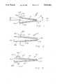
- FIG. 1is a cross-sectional view of one embodiment of the disposable insertion probe
- FIG. 2is a cross-sectional view of a second embodiment of a disposable insertion probe
- FIG. 3is a cross-sectional view of a third embodiment of the disposable insertion probe
- FIG. 4is a cross-sectional view of the insertion probe of FIG. 1 in combination with an infrared radiation detecting device
- FIG. 5is cross-sectional view of the probe of FIG. 3 in combination with an alternate infrared radiation detecting device.
- the inventionis embodied in a probe for use in combination with an infrared radiation detecting device.
- the probeis disposable, and may be used in combination with the infrared detecting device as a medical infrared thermometer for taking temperatures of patients by way of the auditory canal, or other body cavities.
- the probeis open at both ends and includes an inner reflective surface to maximize its performance as a negative cone channel objective lens in collimating infrared radiation from a wide acceptance angle.
- a probefor use in combination with an infrared radiation detecting device, having means for retaining said probe, and means for focusing infrared radiation transmitted through said probe to an infrared sensor, said probe comprising a generally frusto-conical body portion having a narrow forward end and a wide rearward end; said body portion having an inner reflective surface; and flange means projecting radially outward from said body portion for abutting a portion of said device.
- the inventionprovides for the combination of an infrared thermometer having means for focusing infra-red radiation on an infrared radiation sensor, and a negative cone-channel collimating probe, said infrared detecting device having means for releasably retaining said probe, said probe comprising: a generally frusto-conical body portion having a narrow forward end and a wide rearward end; said body portion having an inner reflective surface; and flange means projecting radially outward from said body portion for abutting a portion of said device; whereby said probe functions as an objective lens of said infrared radiation detecting device.
- a preferred disposable infrared thermometer insertion probe 10includes a body portion 12, a narrowed forward end 14, and a widened rearward end 16.
- the probethus has the general shape of a truncated hollow cone.
- the frusto-conical hollow bodyis open at the forward and rearward ends 18 and 20 to allow for maximum transmission of infrared radiation through the probe.
- the body portionis also preferably composed substantially of a closed cell plastic foam, such as polystyrene, which serves as insulation to prevent the probe from absorbing or thermally conducting heat from any source.
- the probehas an inner reflective surface 22, whose primary purpose is reflecting infrared radiation entering at the forward opening 18 through the probe to exit at the rearward end, without substantial diminution in the amount of infrared radiation collected.
- Another major advantage of the high reflectance of the inner surfaceis the reduction of infrared radiation being absorbed by the probe, to prevent the probe from acting as a radiating body itself, which would tend to introduce error in the temperature readings of the detector.
- the inner reflective surface of the body portionis made of a Mylar film, a product of Du Pont de Nemours, E. I. & Co., which is essentially a polyester film having a highly reflective aluminized surface which will give a reflective of about 99% in the probe.
- the inner surface of the body portionitself may be provided with a metallized reflective surface, such as by vapor deposition of a reflective metal upon the inner surface of the body of the probe.
- a dielectric coatingmay be, for example, MgS 2 , which will prevent oxidation of an aluminum surface and provide abrasion resistance.
- aluminumis the metal of choice for metalization of the inner surface, other coatings which would provide an inexpensive high reflection surface may also be appropriate.
- a preferred disposable insertion probealso includes a flange 23 projecting radially outward from the rearward end of the probe, to provide an abutment surface 24 on the flange for abutting a surface of the housing or retaining means of the infrared thermometer. Since the probe serves as an objective lens, and the focal length of the probe with respect to the internal optics of the infrared thermometer is critical, the abutment edge 24 of the flange allows for accurate positioning of the probe with respect to the infrared thermometer.
- a shoulder portion 25 on the forward edge of the flange 23offers a surface for engagement by retaining means on the infrared thermometer, as will be further described hereinafter.
- the acceptance half angle ⁇represents the widest angle at which infrared radiation will be accepted by the probe and transmitted to exit through the rearward end.
- the exit half angle ⁇represents the angle about the center line at which the infrared radiation entering at the maximum acceptance half angle ⁇ will exit the rearward end of the probe.
- the numerical aperture of the probeis the sine of acceptance half angle ⁇ .
- a design goal for the dimensions and optics of the probeis to provide as large a numerical aperture as possible for the acceptance half angle ⁇ and as small a numerical aperture as possible for the exit angle ⁇ .
- the probetherefore performs as a negative or diverging cone channel object lens.
- the small numerical aperture at the rearward end of the probemeans that the energy transmitted through the probe is largely but not completely collimated. It is therefore necessary to provide further condensation of the optical field with one or more auxiliary lenses.
- the further condensation of the infrared radiationis accomplished with a focusing lens and a positive cone channel condensor detector field lens, which will be described further.
- a typical inner diameter at the forward end of the insertion probemay be 0.5 cm or smaller, so that the probe of the present invention therefore utilizes the focusing characteristics of a cone channel collimating lens to maximize the numerical aperture of the object end of the objective lens.
- the energy collecting ability of the objective lensis proportional to the square of the numerical aperture of the lens.
- the optical gain of the probe as an objective lensis proportional to R 1 2 Sin 2 ⁇ , where R 1 is the aperature radius at the forward or objective end of the probe.
- the collimating power or the focusing power of the lensis R 2 /R 1 where R 2 is the radius of the aperture at the image or rearward end of the probe.
- the exit angle ⁇would be approximately 35°. Narrowing the object aperture radius to 0.05 inches would produce an exit angle ⁇ of approximately 17 degrees. Therefore, the diverging beam from the probe requires a further positive, focusing lens to further collimate and focus the infrared radiation to the infrared sensor.
- the inner surface of the probeis an excellent reflector, the absorptance and emissivity of the inner surface are minimal so that the probe would not be expected to radiate error signals to the detector, even if the inner surface of the probe is at a temperature different from that of the detector.
- the inner surface of the probeneed not provide good insulation, but the outer surface of the probe should not absorb or conduct thermal energy from the walls of the cavity into which it is inserted, which would upset the cavity's thermal balance, which is to be measured. Therefore, the outside surface of the probe should consist substantially of a material which is a good insulator, such as a polystyrene closed cell plastic foam, which would possess a very low thermal capacity, and very low thermal conductivity.
- a second embodiment of the insertion probeincludes a frusto-conical extension 28 of the inner surface 22' beyond the rearward end 16' and the flange 23'. It is important that the optical reflecting surface of the probe cone extend very close to the internal optics of the infrared thermometer, particularly as some amount of the infrared radiation will be diverging from the rearward end of the probe, which would result in the loss of some of this radiation and possibly some absorption of the radiation by portions of the housing of the infrared thermometer.
- a third embodiment of the insertion probealso includes an extension 20" of the internal reflecting surface rearward of the rearward end and flange.
- the extension portioncan be seen in FIG. 5 to extend very close to the focusing lens of the internal optics of the infrared thermometer.
- FIG. 4it can be seen how the probe 10 is secured to and released from the housing of the infrared thermometer.
- the jaws or detents 30a and 30bmove radially inwardly and outwardly to grasp the shoulder portions 25, 25', 25"(FIGS. 1-3). Abutment surfaces 24, 24' and 24" abuts against a portion of the housing of the infrared thermometer, for accurate positioning of the insertion probe.
- the infrared thermometerincludes a layer of insulation to keep the optics and sensor at a relatively stable temperature.
- a high mass heat sink 34preferably of aluminum, contained within the housing 36 of the infrared thermometer.
- a shutter mechanism 37is provided between the insertion probe and the focusing lens 38, located at the wide end of a positive condensor cone channel 39.
- a detector sensor 40Located at the image end of the condensor cone channel is a detector sensor 40, which may include a band-pass interference filter to block all wavelengths shorter than 7 microns and longer than 20 microns, allowing wavelengths between 7 microns and 20 microns to pass to the sensor. In the preferred embodiment, as is shown in FIG.
- one or more push rods 42a, 42bare provided to allow the operator of the infrared thermometer to eject the insertion probe.
- O-rings 43seal the passageways for the push rods from the entrance of extraneous heat which may cause errors in the fine readings of the infrared sensor.
- a spring 44may also be provided for spring actuation of the ejection mechanism, which may be assisted by pressure on the push button 45. The biasing of the push rod by the spring 44 in a forward direction is also useful in the detection of an error condition in which the insertion probe may not be fully seated.
- a flange 46 on a push rodpositioned to contact a switch 48 having connections 50 and 52 to the circuitry of the signal processing portion of the infrared thermometer, for generating signal indicating an error condition when the push rod flange is not in contact with the switch 48.
- the reflective inner surface of the insertion probecould also be composed of a dielectric film which has a thickness equal to an odd number of quarter peak infrared wavelengths utilized by the detector is ⁇ micrometers, then dielectric walls having thicknesses of one-quarter ⁇ , three-quarter ⁇ , five-quarter ⁇ , and the like would cause total internal reflection and therefore contain the infrared radiation.
- a tapered light pipecould also serve to provide the inner reflective surface on the insertion probe. The light pipe would have a central cone channel core of the same dimensions as the objective lens described above and would be subject to the same general mathematical principles.
- the materials used to construct the cone channelwould be highly transmissive in the part of the electro-magnetic spectrum used by the detector, 7 microns to 20 microns, such as ZnSe, GEBaF 2 , KRS-6, KRS-5, the like.
- the outer surface of the cone channel light pipe materialwould be clad with a material possessing a higher index of refraction than the cone material, thereby effecting total internal reflection of the infrared waves at the interface of the materials with differing indices of refraction.
- the insertion probe cone channelwould not be hollow, in this configuration, the transmission of infrared radiation would not be occluded by films on the exterior surface of the insertion probe.
- the cone channelAs long as possible, and to make the object end of the probe with as small an outside diameter as possible while making the image end of the cone channel inside diameter as large as possible. It would also be desirable to maximize the collimation powers of the insertion probe as much as possible by making the ratio of the rearward or image end diameter to the diameter of the forward or objective end of the probe as large as possible.
- the disposable infrared thermometer insertion probe of the present inventionprovides a negative cone channel objective lens for an infrared thermometer, to insure the accuracy of infrared temperature readings, and sterile conditions for making such readings in a clinical situation.
- the cone channel insertion probemay be quickly and easily placed onto the infrared thermometer, and ejected for sanitary disposal
- the insertion probehas been described for use with an infrared thermometer, it is clear that the insertion probe may also be used with other infrared detecting devices, and even other devices for measurement of other types of electromagnetic radiation, such as visible light or ultraviolet light.
Landscapes
- General Physics & Mathematics (AREA)
- Spectroscopy & Molecular Physics (AREA)
- Physics & Mathematics (AREA)
- Health & Medical Sciences (AREA)
- Surgery (AREA)
- Life Sciences & Earth Sciences (AREA)
- Biomedical Technology (AREA)
- Molecular Biology (AREA)
- Oral & Maxillofacial Surgery (AREA)
- Engineering & Computer Science (AREA)
- Nuclear Medicine, Radiotherapy & Molecular Imaging (AREA)
- Heart & Thoracic Surgery (AREA)
- Medical Informatics (AREA)
- Pathology (AREA)
- Animal Behavior & Ethology (AREA)
- General Health & Medical Sciences (AREA)
- Public Health (AREA)
- Veterinary Medicine (AREA)
- Measuring And Recording Apparatus For Diagnosis (AREA)
- Radiation Pyrometers (AREA)
Abstract
Description
Claims (4)
Priority Applications (1)
| Application Number | Priority Date | Filing Date | Title |
|---|---|---|---|
| US07/428,416US5046482A (en) | 1988-03-31 | 1989-10-27 | Disposable infrared thermometer insertion probe |
Applications Claiming Priority (2)
| Application Number | Priority Date | Filing Date | Title |
|---|---|---|---|
| US17616988A | 1988-03-31 | 1988-03-31 | |
| US07/428,416US5046482A (en) | 1988-03-31 | 1989-10-27 | Disposable infrared thermometer insertion probe |
Related Parent Applications (1)
| Application Number | Title | Priority Date | Filing Date |
|---|---|---|---|
| US17616988AContinuation | 1988-03-31 | 1988-03-31 |
Publications (1)
| Publication Number | Publication Date |
|---|---|
| US5046482Atrue US5046482A (en) | 1991-09-10 |
Family
ID=26871956
Family Applications (1)
| Application Number | Title | Priority Date | Filing Date |
|---|---|---|---|
| US07/428,416Expired - LifetimeUS5046482A (en) | 1988-03-31 | 1989-10-27 | Disposable infrared thermometer insertion probe |
Country Status (1)
| Country | Link |
|---|---|
| US (1) | US5046482A (en) |
Cited By (34)
| Publication number | Priority date | Publication date | Assignee | Title |
|---|---|---|---|---|
| EP0565123A1 (en)* | 1992-04-08 | 1993-10-13 | Omron Corporation | Radiation clinical thermometer |
| US5487607A (en)* | 1992-04-08 | 1996-01-30 | Omron Corporation | Radiation clinical thermometer |
| USD388172S (en)* | 1995-07-27 | 1997-12-23 | E-Z Kare Good Health Systems, Inc. | Nasal dilator |
| US5833367A (en) | 1996-11-12 | 1998-11-10 | Trutek, Inc. | Tympanic thermometer probe cover |
| US5967992A (en) | 1998-06-03 | 1999-10-19 | Trutex, Inc. | Radiometric temperature measurement based on empirical measurements and linear functions |
| US6001066A (en) | 1997-06-03 | 1999-12-14 | Trutek, Inc. | Tympanic thermometer with modular sensing probe |
| US6030117A (en) | 1996-11-12 | 2000-02-29 | Trutek, Inc. | Tympanic thermometer probe cover |
| US6123454A (en) | 1999-06-11 | 2000-09-26 | Trutek, Inc. | Tympanic thermometer disposable probe cover with further stretching prevention structure |
| US20020068876A1 (en)* | 1999-11-24 | 2002-06-06 | Exergen Corporation | Temporal thermometer disposable cap |
| US6435711B1 (en) | 1998-09-15 | 2002-08-20 | Jonathan Gerlitz | Infrared ear thermometer |
| US20040242976A1 (en)* | 2002-04-22 | 2004-12-02 | Abreu Marcio Marc | Apparatus and method for measuring biologic parameters |
| US20050226307A1 (en)* | 2004-04-07 | 2005-10-13 | Sherin Lussier | Infrared thermometer |
| US20060120432A1 (en)* | 2003-01-06 | 2006-06-08 | Loren Lantz | Tympanic thermometer with ejection mechanism |
| US20060203884A1 (en)* | 2005-03-11 | 2006-09-14 | Brian Sundberg | Adaptable probe assembly for a measuring instrument |
| US20080089387A1 (en)* | 2006-04-21 | 2008-04-17 | Sherwood Services Ag | Probe Cover Having a Blackbody |
| US20090092172A1 (en)* | 2003-01-06 | 2009-04-09 | Sherwood Services Ag | Probe cover cassette with improved probe cover support |
| WO2009085184A1 (en)* | 2007-12-21 | 2009-07-09 | University Of Akron | Protected metallic tip or metallized scanning probe microscopy tip for optical applications |
| US20110194585A1 (en)* | 2010-02-09 | 2011-08-11 | Abhishek Shrivastava | Multiple object non-contact thermometer |
| US20110228810A1 (en)* | 2010-02-09 | 2011-09-22 | O'hara Gary | Multiple object talking non-contact thermometer |
| CN101762324B (en)* | 2008-11-25 | 2011-11-09 | 深圳市大族激光科技股份有限公司 | LED (light emitting diode) light spectrum detecting device |
| USRE43745E1 (en) | 2005-11-23 | 2012-10-16 | Tyco Healthcare Group Lp | Tympanic thermometer probe cover with film support mechanism |
| US20140046141A1 (en)* | 2009-11-10 | 2014-02-13 | Invuity, Inc. | Illuminated suction apparatus |
| US8834020B2 (en) | 2003-04-22 | 2014-09-16 | Geelux Holdings, Ltd. | Thermal imaging system |
| US9301719B2 (en) | 2002-04-22 | 2016-04-05 | Geelux Holding, Ltd. | Apparatus and method for measuring biologic parameters |
| US9357930B2 (en) | 2012-03-19 | 2016-06-07 | Welch Allyn, Inc. | Temperature measurement system |
| US9383236B2 (en)* | 2014-09-18 | 2016-07-05 | Dieterich Standard, Inc. | Process measurement probe bottoming indicator |
| US9445767B2 (en) | 2005-10-24 | 2016-09-20 | Geelux Holdings, Ltd. | Apparatus and method for measuring biologic parameters |
| US9848815B2 (en) | 2002-04-22 | 2017-12-26 | Geelux Holdings, Ltd. | Apparatus and method for measuring biologic parameters |
| US10227063B2 (en) | 2004-02-26 | 2019-03-12 | Geelux Holdings, Ltd. | Method and apparatus for biological evaluation |
| US10238847B2 (en) | 2014-01-22 | 2019-03-26 | Geelux Holdings, Ltd. | Devices and methods for transdermal drug delivery |
| US10251776B2 (en) | 2014-01-10 | 2019-04-09 | Geelux Holding, Ltd. | Devices configured to monitor biological parameters, and to provide treatment, at an Abreu brain thermal tunnel |
| US10335040B2 (en) | 2014-01-10 | 2019-07-02 | Geelux Holdings, Ltd. | Device for measuring the infrared output of the Abreu brain thermal tunnel |
| US11497405B2 (en) | 2013-10-11 | 2022-11-15 | Brain Tunnelgenix Technologies Corp. | Method and apparatus for biological evaluation |
| US11872018B2 (en) | 2015-03-10 | 2024-01-16 | Brain Tunnelgenix Technologies Corp. | Devices, apparatuses, systems, and methods for measuring temperature of an ABTT terminus |
Citations (8)
| Publication number | Priority date | Publication date | Assignee | Title |
|---|---|---|---|---|
| US3282106A (en)* | 1963-01-28 | 1966-11-01 | Barnes Eng Co | Method of measuring body temperature |
| US3531992A (en)* | 1968-07-12 | 1970-10-06 | Leeds & Northrup Co | Expendable tympanic membrane thermometer |
| US3581570A (en)* | 1967-09-05 | 1971-06-01 | Garrett Corp | Thermal radiation sensor |
| US3751664A (en)* | 1972-08-07 | 1973-08-07 | Barnes Eng Co | Infrared detector system |
| US3878836A (en)* | 1973-08-23 | 1975-04-22 | Products Int Marketing | Disposable speculum for tympanic thermometer |
| US4602642A (en)* | 1984-10-23 | 1986-07-29 | Intelligent Medical Systems, Inc. | Method and apparatus for measuring internal body temperature utilizing infrared emissions |
| US4634294A (en)* | 1979-09-12 | 1987-01-06 | Raytek, Inc. | Hand-held digital temperature measuring instrument |
| US4662360A (en)* | 1984-10-23 | 1987-05-05 | Intelligent Medical Systems, Inc. | Disposable speculum |
- 1989
- 1989-10-27USUS07/428,416patent/US5046482A/ennot_activeExpired - Lifetime
Patent Citations (8)
| Publication number | Priority date | Publication date | Assignee | Title |
|---|---|---|---|---|
| US3282106A (en)* | 1963-01-28 | 1966-11-01 | Barnes Eng Co | Method of measuring body temperature |
| US3581570A (en)* | 1967-09-05 | 1971-06-01 | Garrett Corp | Thermal radiation sensor |
| US3531992A (en)* | 1968-07-12 | 1970-10-06 | Leeds & Northrup Co | Expendable tympanic membrane thermometer |
| US3751664A (en)* | 1972-08-07 | 1973-08-07 | Barnes Eng Co | Infrared detector system |
| US3878836A (en)* | 1973-08-23 | 1975-04-22 | Products Int Marketing | Disposable speculum for tympanic thermometer |
| US4634294A (en)* | 1979-09-12 | 1987-01-06 | Raytek, Inc. | Hand-held digital temperature measuring instrument |
| US4602642A (en)* | 1984-10-23 | 1986-07-29 | Intelligent Medical Systems, Inc. | Method and apparatus for measuring internal body temperature utilizing infrared emissions |
| US4662360A (en)* | 1984-10-23 | 1987-05-05 | Intelligent Medical Systems, Inc. | Disposable speculum |
Non-Patent Citations (4)
| Title |
|---|
| Smith, Warren, Modern Optical Engineering, pp. 234 236.* |
| Smith, Warren, Modern Optical Engineering, pp. 234-236. |
| Wolfe, William L., Zissis, George J., eds., The Infrared Handbook pp. 9 12 to 9 14, 1978.* |
| Wolfe, William L., Zissis, George J., eds., The Infrared Handbook pp. 9-12 to 9-14, 1978. |
Cited By (67)
| Publication number | Priority date | Publication date | Assignee | Title |
|---|---|---|---|---|
| US5487607A (en)* | 1992-04-08 | 1996-01-30 | Omron Corporation | Radiation clinical thermometer |
| EP0565123A1 (en)* | 1992-04-08 | 1993-10-13 | Omron Corporation | Radiation clinical thermometer |
| USD388172S (en)* | 1995-07-27 | 1997-12-23 | E-Z Kare Good Health Systems, Inc. | Nasal dilator |
| US5833367A (en) | 1996-11-12 | 1998-11-10 | Trutek, Inc. | Tympanic thermometer probe cover |
| US6030117A (en) | 1996-11-12 | 2000-02-29 | Trutek, Inc. | Tympanic thermometer probe cover |
| US6042266A (en) | 1996-11-12 | 2000-03-28 | Trutek, Inc. | Tympanic thermometer probe cover |
| US6186959B1 (en) | 1997-06-03 | 2001-02-13 | Trutek, Inc. | Tympanic thermometer with modular sensing probe |
| US6001066A (en) | 1997-06-03 | 1999-12-14 | Trutek, Inc. | Tympanic thermometer with modular sensing probe |
| US5967992A (en) | 1998-06-03 | 1999-10-19 | Trutex, Inc. | Radiometric temperature measurement based on empirical measurements and linear functions |
| US20030016728A1 (en)* | 1998-09-15 | 2003-01-23 | Jonathan Gerlitz | Infrared thermometer |
| US6435711B1 (en) | 1998-09-15 | 2002-08-20 | Jonathan Gerlitz | Infrared ear thermometer |
| US6991368B2 (en) | 1998-09-15 | 2006-01-31 | Jonathan Gerlitz | Infrared thermometer |
| US6811306B2 (en) | 1998-09-15 | 2004-11-02 | Jonathan Gerlitz | Infrared ear thermometer |
| US6123454A (en) | 1999-06-11 | 2000-09-26 | Trutek, Inc. | Tympanic thermometer disposable probe cover with further stretching prevention structure |
| US20020068876A1 (en)* | 1999-11-24 | 2002-06-06 | Exergen Corporation | Temporal thermometer disposable cap |
| US6932775B2 (en) | 1999-11-24 | 2005-08-23 | Exergen Corporation | Temporal thermometer disposable cap |
| US20040242976A1 (en)* | 2002-04-22 | 2004-12-02 | Abreu Marcio Marc | Apparatus and method for measuring biologic parameters |
| US9848815B2 (en) | 2002-04-22 | 2017-12-26 | Geelux Holdings, Ltd. | Apparatus and method for measuring biologic parameters |
| US8849379B2 (en)* | 2002-04-22 | 2014-09-30 | Geelux Holdings, Ltd. | Apparatus and method for measuring biologic parameters |
| US10729371B2 (en) | 2002-04-22 | 2020-08-04 | Geelux Holdings Ltd. | Apparatus and method for measuring biologic parameters |
| US10123732B2 (en) | 2002-04-22 | 2018-11-13 | Geelux Holdings, Ltd. | Apparatus and method for measuring biologic parameters |
| US9301719B2 (en) | 2002-04-22 | 2016-04-05 | Geelux Holding, Ltd. | Apparatus and method for measuring biologic parameters |
| US10052030B2 (en) | 2002-04-22 | 2018-08-21 | Geelux Holdings, Ltd. | Apparatus and method for measuring biologic parameters |
| US11045092B2 (en) | 2002-04-22 | 2021-06-29 | Geelux Holdings, Ltd. | Apparatus and method for measuring biologic parameters |
| US9833150B2 (en) | 2002-04-22 | 2017-12-05 | Geelux Holdings, Ltd. | Apparatus and method for measuring biologic parameters |
| US9398856B2 (en) | 2002-04-22 | 2016-07-26 | Geelux Holdings, Ltd. | Thermal imaging system |
| US9408572B2 (en) | 2002-04-22 | 2016-08-09 | Geelux Holdings, Ltd. | Apparatus and method for measuring biologic parameters |
| US7927012B2 (en) | 2003-01-06 | 2011-04-19 | Covidien Ag | Probe cover cassette with improved probe cover support |
| US20090092172A1 (en)* | 2003-01-06 | 2009-04-09 | Sherwood Services Ag | Probe cover cassette with improved probe cover support |
| US20060120432A1 (en)* | 2003-01-06 | 2006-06-08 | Loren Lantz | Tympanic thermometer with ejection mechanism |
| US8834020B2 (en) | 2003-04-22 | 2014-09-16 | Geelux Holdings, Ltd. | Thermal imaging system |
| US10227063B2 (en) | 2004-02-26 | 2019-03-12 | Geelux Holdings, Ltd. | Method and apparatus for biological evaluation |
| US20050226307A1 (en)* | 2004-04-07 | 2005-10-13 | Sherin Lussier | Infrared thermometer |
| US20060203884A1 (en)* | 2005-03-11 | 2006-09-14 | Brian Sundberg | Adaptable probe assembly for a measuring instrument |
| US10448890B2 (en) | 2005-10-24 | 2019-10-22 | Geelux Holdings, Ltd. | Apparatus and method for measuring biologic parameters |
| US9445767B2 (en) | 2005-10-24 | 2016-09-20 | Geelux Holdings, Ltd. | Apparatus and method for measuring biologic parameters |
| USRE43745E1 (en) | 2005-11-23 | 2012-10-16 | Tyco Healthcare Group Lp | Tympanic thermometer probe cover with film support mechanism |
| US8123401B2 (en) | 2006-04-21 | 2012-02-28 | Covidien Ag | Probe cover having a blackbody |
| US20080089387A1 (en)* | 2006-04-21 | 2008-04-17 | Sherwood Services Ag | Probe Cover Having a Blackbody |
| US7530738B2 (en) | 2006-04-21 | 2009-05-12 | Covidien Ag | Probe cover having a blackbody |
| US20110010808A1 (en)* | 2007-12-21 | 2011-01-13 | The University Of Akron | Protected metallic tip or metallized scanning probe microscopy tip for optical applications |
| WO2009085184A1 (en)* | 2007-12-21 | 2009-07-09 | University Of Akron | Protected metallic tip or metallized scanning probe microscopy tip for optical applications |
| CN101762324B (en)* | 2008-11-25 | 2011-11-09 | 深圳市大族激光科技股份有限公司 | LED (light emitting diode) light spectrum detecting device |
| US9636182B2 (en) | 2009-11-10 | 2017-05-02 | Invuity, Inc. | Illuminated suction apparatus |
| US9833295B2 (en)* | 2009-11-10 | 2017-12-05 | Invuity, Inc. | Illuminated suction apparatus |
| US12251273B2 (en) | 2009-11-10 | 2025-03-18 | Invuity, Inc. | Illuminated suction apparatus |
| US11376093B2 (en) | 2009-11-10 | 2022-07-05 | Invuity, Inc. | Illuminated suction apparatus |
| US20140046141A1 (en)* | 2009-11-10 | 2014-02-13 | Invuity, Inc. | Illuminated suction apparatus |
| US10667882B2 (en) | 2009-11-10 | 2020-06-02 | Invuity, Inc. | Illuminated suction apparatus |
| US20110194585A1 (en)* | 2010-02-09 | 2011-08-11 | Abhishek Shrivastava | Multiple object non-contact thermometer |
| US20110228810A1 (en)* | 2010-02-09 | 2011-09-22 | O'hara Gary | Multiple object talking non-contact thermometer |
| US9357930B2 (en) | 2012-03-19 | 2016-06-07 | Welch Allyn, Inc. | Temperature measurement system |
| US11497405B2 (en) | 2013-10-11 | 2022-11-15 | Brain Tunnelgenix Technologies Corp. | Method and apparatus for biological evaluation |
| US10335040B2 (en) | 2014-01-10 | 2019-07-02 | Geelux Holdings, Ltd. | Device for measuring the infrared output of the Abreu brain thermal tunnel |
| US20240252044A1 (en)* | 2014-01-10 | 2024-08-01 | Brain Tunnelgenix Technologies Corp. | Device for measuring the infrared output of the abreu brain thermal tunnel |
| US12310701B2 (en)* | 2014-01-10 | 2025-05-27 | Brain Tunnelgenix Technologies Corp. | Device for measuring the infrared output of the abreu brain thermal tunnel |
| US10251776B2 (en) | 2014-01-10 | 2019-04-09 | Geelux Holding, Ltd. | Devices configured to monitor biological parameters, and to provide treatment, at an Abreu brain thermal tunnel |
| US10383525B2 (en) | 2014-01-10 | 2019-08-20 | Geelux Holdings, Ltd. | Device for measuring the infrared output of the Abreu brain thermal tunnel |
| US11786394B2 (en) | 2014-01-10 | 2023-10-17 | Brain Tunnelgenix Technologies Corp. | Devices configured to monitor biological parameters, and to provide treatment, at an Abreu brain thermal tunnel |
| US12295880B2 (en) | 2014-01-10 | 2025-05-13 | Brain Tunnelgenix Technologies Corp. | Devices configured to monitor biological parameters, and to provide treatment, at an Abreu brain thermal tunnel |
| US11963742B2 (en) | 2014-01-10 | 2024-04-23 | Brain Tunnelgenix Technologies Corp. | Device for measuring the infrared output of the Abreu brain thermal tunnel |
| US10238847B2 (en) | 2014-01-22 | 2019-03-26 | Geelux Holdings, Ltd. | Devices and methods for transdermal drug delivery |
| US12201796B2 (en) | 2014-01-22 | 2025-01-21 | Brain Tunnelgenix Technologies Corp. | Devices configured to provide treatment at an Abreu brain thermal tunnel |
| US11331461B2 (en) | 2014-01-22 | 2022-05-17 | Brain Tunnelgenix Technologies Corp. | Devices configured to provide treatment at an Abreu brain thermal tunnel |
| US9383236B2 (en)* | 2014-09-18 | 2016-07-05 | Dieterich Standard, Inc. | Process measurement probe bottoming indicator |
| US12102413B2 (en) | 2015-03-10 | 2024-10-01 | Brain Tunnelgenix Technologies Corp. | Devices for measuring temperature of an ABTT terminus |
| US11872018B2 (en) | 2015-03-10 | 2024-01-16 | Brain Tunnelgenix Technologies Corp. | Devices, apparatuses, systems, and methods for measuring temperature of an ABTT terminus |
Similar Documents
| Publication | Publication Date | Title |
|---|---|---|
| US5046482A (en) | Disposable infrared thermometer insertion probe | |
| EP0639063B1 (en) | Optical system for an infrared thermometer | |
| US4494881A (en) | Intra-optical light beam sighting system for an infrared thermometer | |
| KR101622427B1 (en) | Non-contact medical thermometer with stray radiation shielding | |
| US4907895A (en) | Optical chopper for infrared thermometer | |
| US4784149A (en) | Infrared thermometer with automatic calibration | |
| US5018872A (en) | Probe assembly for infrared thermometer | |
| US5860421A (en) | Apparatus and method for calibrating measurement systems | |
| US5626139A (en) | Tympanic thermometer | |
| US6898457B1 (en) | Method for determining temperature, radiation thermometer with several infrared sensor elements | |
| WO1998020790A1 (en) | Radiation thermometer | |
| JPH04232838A (en) | Absorbing cell of fluid sample | |
| KR100788117B1 (en) | Optical cell measurement apparatus | |
| KR20010079808A (en) | Method for determining temperature, radiation thermometer with several infrared sensor elements | |
| US5007432A (en) | Radiation detection method and apparatus | |
| JPH11188008A (en) | Eardrum thermometer | |
| Boboridis et al. | A High‐Speed Four‐Channel Infrared Pyrometer | |
| JP4126792B2 (en) | Radiation thermometer | |
| JP4162066B2 (en) | Radiation thermometer | |
| JP4006803B2 (en) | Radiation thermometer | |
| JP2000139849A (en) | Infrared detector and radiation thermometer using the same | |
| Boothe et al. | Goniometric characteristics of optical fibres for temperature measurement indiesel engine exhaust filters | |
| DeRowe et al. | Optical-fiber-coupled inferometric measurement of tympanic membrane temperature: a new diagnostic tool for acute otitis media | |
| JPH11197119A (en) | Radiation thermometer | |
| GB2161924A (en) | Reflex pyrometer sighting |
Legal Events
| Date | Code | Title | Description |
|---|---|---|---|
| STCF | Information on status: patent grant | Free format text:PATENTED CASE | |
| CC | Certificate of correction | ||
| FPAY | Fee payment | Year of fee payment:4 | |
| AS | Assignment | Owner name:IVAC MEDICAL SYSTEMS, INC., CALIFORNIA Free format text:CHANGE OF NAME;ASSIGNOR:IVAC CORPORATION;REEL/FRAME:007986/0971 Effective date:19960125 | |
| AS | Assignment | Owner name:BANKERS TRUST COMPANY, NEW YORK Free format text:SECURITY INTEREST;ASSIGNOR:IVAC HOLDINGS, INC.;REEL/FRAME:008568/0540 Effective date:19961126 | |
| AS | Assignment | Owner name:IVAC HOLDINGS, INC., CALIFORNIA Free format text:MERGER;ASSIGNOR:IVAC MEDICAL SYSTEMS, INC.;REEL/FRAME:008621/0113 Effective date:19961126 Owner name:ALARIS MEDICAL SYSTEMS, INC., CALIFORNIA Free format text:CHANGE OF NAME;ASSIGNOR:IVAC HOLDINGS, INC.;REEL/FRAME:008621/0107 Effective date:19970429 | |
| FPAY | Fee payment | Year of fee payment:8 | |
| AS | Assignment | Owner name:IISBC BANK USA, NEW YORK Free format text:SECURITY INTEREST;ASSIGNOR:ALARIS MEDICAL SYSTEMS, INC.;REEL/FRAME:013403/0338 Effective date:20011016 | |
| FEPP | Fee payment procedure | Free format text:PAYOR NUMBER ASSIGNED (ORIGINAL EVENT CODE: ASPN); ENTITY STATUS OF PATENT OWNER: LARGE ENTITY Free format text:PAYER NUMBER DE-ASSIGNED (ORIGINAL EVENT CODE: RMPN); ENTITY STATUS OF PATENT OWNER: LARGE ENTITY | |
| FPAY | Fee payment | Year of fee payment:12 | |
| AS | Assignment | Owner name:ALARIS MEDICAL SYSTEMS, INC., CALIFORNIA Free format text:CHANGE OF NAME;ASSIGNOR:ALARIS MEDICAL, INC.;REEL/FRAME:014201/0592 Effective date:20030630 Owner name:ALARIS MEDICAL SYSTEMS, INC., CALIFORNIA Free format text:SECURITY AGREEMENT;ASSIGNOR:HSBC BANK USA;REEL/FRAME:014220/0171 Effective date:20030630 Owner name:ALARIS MEDICAL, INC., CALIFORNIA Free format text:MERGER;ASSIGNOR:ALARIS MEDICAL SYSTEMS, INC.;REEL/FRAME:014220/0417 Effective date:20030630 Owner name:CITICORP NORTH AMERICA, INC., NEW YORK Free format text:SECURITY AGREEMENT;ASSIGNOR:ALARIS MEDICAL SYSTEMS, INC.;REEL/FRAME:014220/0315 Effective date:20030630 | |
| AS | Assignment | Owner name:ALARIS MEDICAL SYSTEMS, INC., CALIFORNIA Free format text:RELEASE OF SECURITY AGREEMENT;ASSIGNOR:CITICORP NORTH AMERICA, INC.;REEL/FRAME:015703/0127 Effective date:20040707 | |
| AS | Assignment | Owner name:CARDINAL HEALTH 303, INC., CALIFORNIA Free format text:CHANGE OF NAME;ASSIGNOR:ALARIS MEDICAL SYSTEMS, INC.;REEL/FRAME:016937/0304 Effective date:20041013 |