US5046365A - Transducer thermal protection system - Google Patents
Transducer thermal protection systemDownload PDFInfo
- Publication number
- US5046365A US5046365AUS07/553,033US55303390AUS5046365AUS 5046365 AUS5046365 AUS 5046365AUS 55303390 AUS55303390 AUS 55303390AUS 5046365 AUS5046365 AUS 5046365A
- Authority
- US
- United States
- Prior art keywords
- transducer
- approximately
- degrees
- hollow cavity
- thermal protection
- Prior art date
- Legal status (The legal status is an assumption and is not a legal conclusion. Google has not performed a legal analysis and makes no representation as to the accuracy of the status listed.)
- Expired - Lifetime
Links
- HCHKCACWOHOZIP-UHFFFAOYSA-NZincChemical compound[Zn]HCHKCACWOHOZIP-UHFFFAOYSA-N0.000claimsabstractdescription8
- 239000011888foilSubstances0.000claimsabstractdescription7
- 239000011701zincSubstances0.000claimsabstractdescription7
- 229910052725zincInorganic materials0.000claimsabstractdescription7
- 239000007791liquid phaseSubstances0.000claimsabstractdescription4
- 239000012774insulation materialSubstances0.000claimsabstract3
- 239000007787solidSubstances0.000claimsdescription7
- 229910001026inconelInorganic materials0.000claimsdescription5
- 238000009413insulationMethods0.000claimsdescription5
- 229910052751metalInorganic materials0.000claimsdescription5
- 239000002184metalSubstances0.000claimsdescription5
- RYGMFSIKBFXOCR-UHFFFAOYSA-NCopperChemical compound[Cu]RYGMFSIKBFXOCR-UHFFFAOYSA-N0.000claimsdescription2
- 229910052802copperInorganic materials0.000claimsdescription2
- 239000010949copperSubstances0.000claimsdescription2
- 238000002844meltingMethods0.000claimsdescription2
- 230000008018meltingEffects0.000claimsdescription2
- 229910000601superalloyInorganic materials0.000claims2
- 239000000956alloySubstances0.000claims1
- 239000004020conductorSubstances0.000claims1
- 239000000155meltSubstances0.000claims1
- 238000001816coolingMethods0.000abstractdescription7
- 239000012071phaseSubstances0.000abstractdescription6
- XLYOFNOQVPJJNP-UHFFFAOYSA-NwaterSubstancesOXLYOFNOQVPJJNP-UHFFFAOYSA-N0.000description11
- 239000007788liquidSubstances0.000description5
- 230000003750conditioning effectEffects0.000description4
- POIUWJQBRNEFGX-XAMSXPGMSA-NcathelicidinChemical compoundC([C@@H](C(=O)N[C@@H](CCCNC(N)=N)C(=O)N[C@@H](CCCCN)C(=O)N[C@@H](CO)C(=O)N[C@@H](CCCCN)C(=O)N[C@@H](CCC(O)=O)C(=O)N[C@@H](CCCCN)C(=O)N[C@@H]([C@@H](C)CC)C(=O)NCC(=O)N[C@@H](CCCCN)C(=O)N[C@@H](CCC(O)=O)C(=O)N[C@@H](CC=1C=CC=CC=1)C(=O)N[C@@H](CCCCN)C(=O)N[C@@H](CCCNC(N)=N)C(=O)N[C@@H]([C@@H](C)CC)C(=O)N[C@@H](C(C)C)C(=O)N[C@@H](CCC(N)=O)C(=O)N[C@@H](CCCNC(N)=N)C(=O)N[C@@H]([C@@H](C)CC)C(=O)N[C@@H](CCCCN)C(=O)N[C@@H](CC(O)=O)C(=O)N[C@@H](CC=1C=CC=CC=1)C(=O)N[C@@H](CC(C)C)C(=O)N[C@@H](CCCNC(N)=N)C(=O)N[C@@H](CC(N)=O)C(=O)N[C@@H](CC(C)C)C(=O)N[C@@H](C(C)C)C(=O)N1[C@@H](CCC1)C(=O)N[C@@H](CCCNC(N)=N)C(=O)N[C@@H]([C@@H](C)O)C(=O)N[C@@H](CCC(O)=O)C(=O)N[C@@H](CO)C(O)=O)NC(=O)[C@H](CC=1C=CC=CC=1)NC(=O)[C@H](CC(O)=O)NC(=O)CNC(=O)[C@H](CC(C)C)NC(=O)[C@@H](N)CC(C)C)C1=CC=CC=C1POIUWJQBRNEFGX-XAMSXPGMSA-N0.000description3
- 239000002826coolantSubstances0.000description2
- 239000000463materialSubstances0.000description2
- 229910000831SteelInorganic materials0.000description1
- 238000006243chemical reactionMethods0.000description1
- 238000010276constructionMethods0.000description1
- 230000007613environmental effectEffects0.000description1
- CPLXHLVBOLITMK-UHFFFAOYSA-Nmagnesium oxideInorganic materials[Mg]=OCPLXHLVBOLITMK-UHFFFAOYSA-N0.000description1
- 239000000395magnesium oxideSubstances0.000description1
- AXZKOIWUVFPNLO-UHFFFAOYSA-Nmagnesium;oxygen(2-)Chemical compound[O-2].[Mg+2]AXZKOIWUVFPNLO-UHFFFAOYSA-N0.000description1
- 238000012423maintenanceMethods0.000description1
- 238000000034methodMethods0.000description1
- 238000012544monitoring processMethods0.000description1
- 239000010955niobiumSubstances0.000description1
- GUCVJGMIXFAOAE-UHFFFAOYSA-Nniobium atomChemical compound[Nb]GUCVJGMIXFAOAE-UHFFFAOYSA-N0.000description1
- 239000012782phase change materialSubstances0.000description1
- 239000010959steelSubstances0.000description1
Images

Classifications
- G—PHYSICS
- G01—MEASURING; TESTING
- G01K—MEASURING TEMPERATURE; MEASURING QUANTITY OF HEAT; THERMALLY-SENSITIVE ELEMENTS NOT OTHERWISE PROVIDED FOR
- G01K1/00—Details of thermometers not specially adapted for particular types of thermometer
- G01K1/08—Protective devices, e.g. casings
- G01K1/12—Protective devices, e.g. casings for preventing damage due to heat overloading
- G—PHYSICS
- G01—MEASURING; TESTING
- G01D—MEASURING NOT SPECIALLY ADAPTED FOR A SPECIFIC VARIABLE; ARRANGEMENTS FOR MEASURING TWO OR MORE VARIABLES NOT COVERED IN A SINGLE OTHER SUBCLASS; TARIFF METERING APPARATUS; MEASURING OR TESTING NOT OTHERWISE PROVIDED FOR
- G01D3/00—Indicating or recording apparatus with provision for the special purposes referred to in the subgroups
- G01D3/08—Indicating or recording apparatus with provision for the special purposes referred to in the subgroups with provision for safeguarding the apparatus, e.g. against abnormal operation, against breakdown
- G—PHYSICS
- G01—MEASURING; TESTING
- G01L—MEASURING FORCE, STRESS, TORQUE, WORK, MECHANICAL POWER, MECHANICAL EFFICIENCY, OR FLUID PRESSURE
- G01L19/00—Details of, or accessories for, apparatus for measuring steady or quasi-steady pressure of a fluent medium insofar as such details or accessories are not special to particular types of pressure gauges
- G01L19/06—Means for preventing overload or deleterious influence of the measured medium on the measuring device or vice versa
- G01L19/0681—Protection against excessive heat
Definitions
- the inventionis directed to heat sink and insulation systems and more particularly to thermal protection systems for all types of transducers used in instrumentation so that those transducers can be used in high temperature environments where the environmental temperature exceed the maximum high temperature limits of those transducers.
- sensors and/or signal conditioning componentshave a low maximum operating temperature in the range of from 200 to 900 degrees F. and cannot be directly utilized in areas that exceed these temperature range limits. In many areas it becomes necessary to monitor these areas. Presently, monitoring or signal conditioning in these required high temperature areas is virtually impossible.
- This inventionis directed to the thermal protection of low heat tolerance instrumentation and signal conditioning devices.
- sensorssuch as pressure and signal conditional components, for example, generally have a low maximum operating temperature (200 degrees F. to 900 degrees F.). To remain operative and operate accurately during exposure to environment temperatures greater than 2000 degrees F. suitable thermal protection is required.
- Protectioncan be accomplished by using phase change heat sinks and thermoelectric cooling along with a multi-foil insolation around the sensor.
- the solid-to-liquid phase change of zinc metalis utilized to protect sensors capable of operation above the melting point of zinc which is in the order of 787 degrees F.
- This cooling systemis completely passive and requires no maintenance of the cooling medium (zinc form solid to liquid) during its life.
- water to steamis utilized for the phase change cooling medium for sensors capable of operation above 212 degrees F.
- the internal water holding meansis allowed to vent to the atmosphere after a liquid to gas phase change.
- the low internal temperature(212 degrees F.) allows protection of the sensors.
- a refill of water after useallows repeated use.
- thermoelectric transducerin combination of a phase change material, such as mentioned above, to maintain a maximum temperature in the range of 230 degrees F. Internal or external power is required for its operation.
- each of the above embodimentis generally constructed from thin inconel foils preferably having a thickness in the range of 0.015 to 0.007 inches. A foil thickness of around 0.010 inches works well.
- An object of this inventionis to provide heat protection to low temperature tolerant sensors employed in a high temperature environment.
- Another object of this inventionis to provide solid to liquid phase change material for sensor protection in high temperature environment.
- Still another object of this inventionis to provide liquid to gas phase change liquid for sensor protection in high temperature environments.
- Yet another object of this inventionis to provide thermoelectric cooling for maintaining a constant operating temperature environment to a sensor when that sensor is positioned in a high temperature environment.
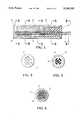
- FIG. 1is a cutaway showing of the first embodiment of the invention:
- FIG. 2is an end view taken along line 2--2 of FIG. 1;
- FIG. 3is a view taken along line 3--3 of FIG. 1;
- FIG. 4is a view taken along line 4--4 of FIG. 1;
- FIG. 5is a view taken along line 5--5 of FIG. 1;
- FIG. 6is a view taken along line 6--6 of FIG. 1;
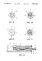
- FIG. 7is a cutaway showing of a second embodiment of the invention.
- FIG. 8is an end view taken along line 8--8 of FIG. 7;
- FIG. 9is a view taken along line 9--9 of FIG. 7;
- FIG. 10is a view taken along line 10--10 of FIG. 7;
- FIG. 11is a view taken along line 11--11 of FIG. 7;
- FIG. 12is a view taken along line 12--12 of FIG. 7;
- FIG. 13is a cutaway showing of a third embodiment of the invention.
- FIGS. 1-6depicts the first embodiment of the present invention.
- a multi-foil constructed case or jar 10is provide to house the particular sensor to be heat protected.
- This case or jaris constructed of a plurality of inconel foils sheets of approximately 0.75 mils thick. Forty inconel sheets work well for the case or jar construction. The sheets of inconel are spaced apart with Thoria spacers (explain what kind of material this is). The thoria spacers are approximately 3.5 mils thick.
- the transducer 12is encased in solid zinc metal 14, at ambient temperature.
- Wires 16which comprise a pair of 0.030 copper wires insulated with magnesium oxide and covered with a 0.015 thick steel shield resulting in an over all diameter of 0.10 inches. This wire is obtainable under the trade name NANMAC which is readily available. These extend through the end cap 18, see FIG. 2, the molded Mini-K insulation 20 well known in the insulation art through the zinc to a space 22 at the opposite end of the case or jar from the end cap 18.
- the wires 16are formed 180 degrees and are passed through a 0.10 columbium tube 24 in which the transducer 12 is located. The tube 24 extends beyond the end cap 18 and is open to the atmosphere.
- the heat of the environmentcauses the zinc to melt at around 887 degrees F. establishing the operating temperature of the transducer 12.
- FIGS. 7-12depict a second embodiment of the invention.
- the housing 10is constructed as hereinbefore described except the end cap is formed as a part of the housing.
- the housing 10contains a water vessel 26 is located between one end wall 28 of the housing and a space 30 which is filed with molded Min-K insulation 20.
- the water vesselvents to the atmosphere through vent tubes 30.
- Six PCB Model 105 PSIA transducers 32 with a maximum operating temperature of 325 F.are installed in six tubes 24, hereinbefore described. Only one transducer is shown in drawing FIG. 7 for clarity.
- a six transducer scanner 34 having a maximum operating temperature of 257 degrees F.is positioned at one end of the housing adjacent the transducers.
- Wire 16extends from the sensor through the end wall 36 of the housing for connection to the electronic monitor system not shown.
- the water vesselIn operation, the water vessel is filled with water and as the water is heated by the environment in which the transducer is positioned the water changes from a liquid to a gas and vents through vent tubes 30.
- the transducer and scannerwill continue to be in a heat environment of about 212 degrees F. as long as water remains in the vessel for conversion to steam. After use the vessel can be refilled with water and reused.
- FIG. 13depicts two transducers and a scanner of the type hereinbefore shown and discussed under the discussion of FIGS. 7-12 which in addition to the previously discussed embodiments includes a thermoelectric transistor 38 the cold side of which is used for additional cooling.
- the transistor 38is connected externally to a source of power.
- the device of the drawing FIG. 13further includes the cooling by means of the thermotransistor 38 in combination with phase change cooling of the previously described embodiments and can be incorporated with either.
- sensorshave been described as pressure transducers for ease of explanation and any type sensor can be utilized in place of the pressure transducer to practice the invention.
Landscapes
- Physics & Mathematics (AREA)
- General Physics & Mathematics (AREA)
- Measuring Temperature Or Quantity Of Heat (AREA)
Abstract
Description
Claims (8)
Priority Applications (1)
| Application Number | Priority Date | Filing Date | Title |
|---|---|---|---|
| US07/553,033US5046365A (en) | 1990-07-16 | 1990-07-16 | Transducer thermal protection system |
Applications Claiming Priority (1)
| Application Number | Priority Date | Filing Date | Title |
|---|---|---|---|
| US07/553,033US5046365A (en) | 1990-07-16 | 1990-07-16 | Transducer thermal protection system |
Publications (1)
| Publication Number | Publication Date |
|---|---|
| US5046365Atrue US5046365A (en) | 1991-09-10 |
Family
ID=24207836
Family Applications (1)
| Application Number | Title | Priority Date | Filing Date |
|---|---|---|---|
| US07/553,033Expired - LifetimeUS5046365A (en) | 1990-07-16 | 1990-07-16 | Transducer thermal protection system |
Country Status (1)
| Country | Link |
|---|---|
| US (1) | US5046365A (en) |
Cited By (12)
| Publication number | Priority date | Publication date | Assignee | Title |
|---|---|---|---|---|
| US6032538A (en)* | 1999-03-17 | 2000-03-07 | U.S. Army Corps Of Engineers As Represented By The Secretary Of The Army | Pressure sensor mounting device for high temperature environments |
| DE19914671A1 (en)* | 1999-03-31 | 2000-11-02 | Martin Hess | Pressure transmitter installation on a process line of a process plant and preassembled installation block |
| US6317321B1 (en)* | 1994-11-04 | 2001-11-13 | Compaq Computer Corporation | Lap-top enclosure having surface coated with heat-absorbing phase-change material |
| US20060191344A1 (en)* | 2004-09-24 | 2006-08-31 | Shinichi Hashimoto | Ultrasonic probe |
| US7161802B2 (en)* | 2002-08-02 | 2007-01-09 | Raytheon Company | Thermal management system having porous fluid transfer element |
| WO2016048424A3 (en)* | 2014-09-23 | 2016-08-11 | Rosemount Inc. | Cooling for industrial process variable transmitters |
| US9752947B2 (en) | 2014-09-23 | 2017-09-05 | P I Components Corp. | Thermoelectric heating, cooling and power generation for direct mount and dual compartment fill remote seal systems |
| US9772246B2 (en) | 2014-09-30 | 2017-09-26 | Rosemount Inc. | Fill fluid thermal management |
| CN108414135A (en)* | 2018-01-30 | 2018-08-17 | 哈尔滨工业大学 | A kind of high temperature flow field device for pressure measurement of anti-leak |
| RU2710528C1 (en)* | 2016-09-27 | 2019-12-26 | Пи Ай КОМПОНЕНТС КОРПОРЕЙШН | Thermoelectric heating, cooling and energy generation for systems with remote diaphragm with direct installation and dual compartment for filling liquid |
| US20200003650A1 (en)* | 2018-06-27 | 2020-01-02 | Mks Instruments, Inc. | Apparatus and Method for Thermal Insulation of High-Temperature Pressure Sensors |
| US10866038B2 (en)* | 2018-10-25 | 2020-12-15 | United Arab Emirates University | Heat sinks with vibration enhanced heat transfer for non-liquid heat sources |
Citations (2)
| Publication number | Priority date | Publication date | Assignee | Title |
|---|---|---|---|---|
| US4578994A (en)* | 1980-09-09 | 1986-04-01 | The United States Of America As Represented By The Secretary Of Transportation | Temperature insensitive pressure jump detector |
| US4986126A (en)* | 1990-03-26 | 1991-01-22 | Acustar, Inc. | Transducer with heat sink |
- 1990
- 1990-07-16USUS07/553,033patent/US5046365A/ennot_activeExpired - Lifetime
Patent Citations (2)
| Publication number | Priority date | Publication date | Assignee | Title |
|---|---|---|---|---|
| US4578994A (en)* | 1980-09-09 | 1986-04-01 | The United States Of America As Represented By The Secretary Of Transportation | Temperature insensitive pressure jump detector |
| US4986126A (en)* | 1990-03-26 | 1991-01-22 | Acustar, Inc. | Transducer with heat sink |
Cited By (18)
| Publication number | Priority date | Publication date | Assignee | Title |
|---|---|---|---|---|
| US6317321B1 (en)* | 1994-11-04 | 2001-11-13 | Compaq Computer Corporation | Lap-top enclosure having surface coated with heat-absorbing phase-change material |
| US6032538A (en)* | 1999-03-17 | 2000-03-07 | U.S. Army Corps Of Engineers As Represented By The Secretary Of The Army | Pressure sensor mounting device for high temperature environments |
| DE19914671A1 (en)* | 1999-03-31 | 2000-11-02 | Martin Hess | Pressure transmitter installation on a process line of a process plant and preassembled installation block |
| US7161802B2 (en)* | 2002-08-02 | 2007-01-09 | Raytheon Company | Thermal management system having porous fluid transfer element |
| US20060191344A1 (en)* | 2004-09-24 | 2006-08-31 | Shinichi Hashimoto | Ultrasonic probe |
| US7308828B2 (en)* | 2004-09-24 | 2007-12-18 | Kabushiki Kaisha Toshiba | Ultrasonic probe |
| US9752946B2 (en) | 2014-09-23 | 2017-09-05 | Rosemount Inc. | Cooling for industrial process variable transmitters |
| US9752947B2 (en) | 2014-09-23 | 2017-09-05 | P I Components Corp. | Thermoelectric heating, cooling and power generation for direct mount and dual compartment fill remote seal systems |
| WO2016048424A3 (en)* | 2014-09-23 | 2016-08-11 | Rosemount Inc. | Cooling for industrial process variable transmitters |
| US9772246B2 (en) | 2014-09-30 | 2017-09-26 | Rosemount Inc. | Fill fluid thermal management |
| US11313747B2 (en) | 2014-09-30 | 2022-04-26 | Rosemount Inc. | Fill fluid thermal management |
| RU2710528C1 (en)* | 2016-09-27 | 2019-12-26 | Пи Ай КОМПОНЕНТС КОРПОРЕЙШН | Thermoelectric heating, cooling and energy generation for systems with remote diaphragm with direct installation and dual compartment for filling liquid |
| CN108414135A (en)* | 2018-01-30 | 2018-08-17 | 哈尔滨工业大学 | A kind of high temperature flow field device for pressure measurement of anti-leak |
| CN108414135B (en)* | 2018-01-30 | 2019-02-26 | 哈尔滨工业大学 | A leak-proof high temperature flow field pressure measurement device |
| US20200003650A1 (en)* | 2018-06-27 | 2020-01-02 | Mks Instruments, Inc. | Apparatus and Method for Thermal Insulation of High-Temperature Pressure Sensors |
| US10782200B2 (en)* | 2018-06-27 | 2020-09-22 | Mks Instruments, Inc. | Apparatus and method for thermal insulation of high-temperature pressure sensors |
| US10866038B2 (en)* | 2018-10-25 | 2020-12-15 | United Arab Emirates University | Heat sinks with vibration enhanced heat transfer for non-liquid heat sources |
| US10890387B2 (en)* | 2018-10-25 | 2021-01-12 | United Arab Emirates University | Heat sinks with vibration enhanced heat transfer |
Similar Documents
| Publication | Publication Date | Title |
|---|---|---|
| US5046365A (en) | Transducer thermal protection system | |
| US3713899A (en) | Thermocouple probe | |
| US5864365A (en) | Environmentally controlled camera housing assembly | |
| CN202138519U (en) | Storage box, navigation data recording unit and navigation data recording device | |
| US4440219A (en) | Thermally isolated well instruments | |
| US4513352A (en) | Thermal protection apparatus | |
| US10852198B2 (en) | Temperature sensor of thermal monitoring system for use in power distribution systems | |
| US3754201A (en) | Heat sensitive detector | |
| AU2003258814A1 (en) | Device for thermal insulation of at least a submarine pipeline comprising a phase-change material confined in jackets | |
| US20210123813A1 (en) | Temperature sensor of thermal monitoring system for use in power distribution systems | |
| GB1265470A (en) | ||
| JPS59120834A (en) | Thermocouple device | |
| CN215394143U (en) | High-temperature alarm device of numerical control machine tool | |
| CN107579625A (en) | Motor temperature control device for infrared band test system | |
| CN202481558U (en) | Heat insulation cabinet, navigation data recording unit and navigation data recording device | |
| US6846983B1 (en) | Millivoltage generator | |
| US5951165A (en) | Temperature sensor | |
| US4672920A (en) | Pressure compensated temperature switch unit for protection of an internal combustion engine | |
| JP3003736B2 (en) | Thermal insulation structure of high-temperature battery | |
| CN215181354U (en) | Waterproof industrial camera assembly | |
| RU80609U1 (en) | HEAT FIRE DETECTOR | |
| US3722579A (en) | Heat transfer system for radioisotope generators | |
| CN115691844A (en) | Temperature and humidity probe for monitoring leakage of coolant in nuclear power station | |
| JP2965122B2 (en) | Mounting structure of polymer PTC element and method of mounting polymer PTC element | |
| CH613654A5 (en) | Device for the manufacture of tubes made from thermoplastic resin containing at least one wire or cable |
Legal Events
| Date | Code | Title | Description |
|---|---|---|---|
| AS | Assignment | Owner name:GENERAL DYNAMICS CORPORATION (CONVAIR DIVISION), A Free format text:ASSIGNMENT OF ASSIGNORS INTEREST.;ASSIGNOR:SIMPSON, DANIEL L.;REEL/FRAME:005380/0439 Effective date:19900615 Owner name:GENERAL DYNAMICS CORPORATION (CONVAIR CORPORATION) Free format text:ASSIGNMENT OF ASSIGNORS INTEREST.;ASSIGNOR:SWANSON, KURT W.;REEL/FRAME:005380/0449 Effective date:19900605 Owner name:GENERAL DYNAMICS CORPORATION (CONVAIR DIVISION), A Free format text:ASSIGNMENT OF ASSIGNORS INTEREST.;ASSIGNOR:KUMLEY, MARVIN A.;REEL/FRAME:005380/0429 Effective date:19900606 Owner name:GENERAL DYNAMICS CORPORATION (CONVAIR DIVISION), A Free format text:ASSIGNMENT OF ASSIGNORS INTEREST.;ASSIGNOR:BECK, BRYAN L.;REEL/FRAME:005380/0459 Effective date:19900604 | |
| STCF | Information on status: patent grant | Free format text:PATENTED CASE | |
| AS | Assignment | Owner name:MARTIN MARIETTA CORPORATION, MARYLAND Free format text:ASSIGNMENT OF ASSIGNORS INTEREST;ASSIGNOR:GENERAL DYNAMICS CORPORATION;REEL/FRAME:007197/0822 Effective date:19940819 | |
| REMI | Maintenance fee reminder mailed | ||
| FPAY | Fee payment | Year of fee payment:4 | |
| SULP | Surcharge for late payment | ||
| AS | Assignment | Owner name:LOCKHEED MARTIN CORPORATION, MARYLAND Free format text:MERGER;ASSIGNOR:MARTIN MARIETTA CORPORATION;REEL/FRAME:009414/0706 Effective date:19960125 | |
| REMI | Maintenance fee reminder mailed | ||
| FPAY | Fee payment | Year of fee payment:8 | |
| SULP | Surcharge for late payment | ||
| FEPP | Fee payment procedure | Free format text:PAYOR NUMBER ASSIGNED (ORIGINAL EVENT CODE: ASPN); ENTITY STATUS OF PATENT OWNER: LARGE ENTITY | |
| FPAY | Fee payment | Year of fee payment:12 |