US5046122A - Image compression device - Google Patents
Image compression deviceDownload PDFInfo
- Publication number
- US5046122A US5046122AUS07/458,463US45846389AUS5046122AUS 5046122 AUS5046122 AUS 5046122AUS 45846389 AUS45846389 AUS 45846389AUS 5046122 AUS5046122 AUS 5046122A
- Authority
- US
- United States
- Prior art keywords
- data
- code
- compression device
- bit
- conversion table
- Prior art date
- Legal status (The legal status is an assumption and is not a legal conclusion. Google has not performed a legal analysis and makes no representation as to the accuracy of the status listed.)
- Expired - Lifetime
Links
- 238000007906compressionMethods0.000titleclaimsabstractdescription24
- 230000006835compressionEffects0.000titleclaimsabstractdescription24
- 238000006243chemical reactionMethods0.000claimsabstractdescription24
- 239000000872bufferSubstances0.000claimsdescription13
- 230000008707rearrangementEffects0.000claimsdescription7
- 238000000034methodMethods0.000claimsdescription3
- 239000011159matrix materialSubstances0.000claimsdescription2
- 238000005056compactionMethods0.000claims1
- 238000010586diagramMethods0.000description5
- 238000011144upstream manufacturingMethods0.000description3
- 238000012986modificationMethods0.000description2
- 230000004048modificationEffects0.000description2
- 230000006978adaptationEffects0.000description1
- 230000005540biological transmissionEffects0.000description1
- 238000013144data compressionMethods0.000description1
- 230000003247decreasing effectEffects0.000description1
- 230000007547defectEffects0.000description1
- 238000000638solvent extractionMethods0.000description1
Images


Classifications
- H—ELECTRICITY
- H04—ELECTRIC COMMUNICATION TECHNIQUE
- H04N—PICTORIAL COMMUNICATION, e.g. TELEVISION
- H04N1/00—Scanning, transmission or reproduction of documents or the like, e.g. facsimile transmission; Details thereof
- H04N1/41—Bandwidth or redundancy reduction
- H04N1/4105—Bandwidth or redundancy reduction for halftone screened pictures
Definitions
- This inventionrelates to an image compression device which compresses binary image data at high efficiency and high speed.
- the compression efficiencyis low for processing the binary image data having statistical characteristics (such as resolution) that are different between the main and the auxiliary scanning directions. Since the device processed data in the unit of one bit, the speed of encoding is slow, and hence, the conventional compression device cannot realize the compression at high speed.
- This inventionwas conceived to eliminate such defects encountered in the prior art and aims to provide an image compression device which can compress any binary data including line images and dot images at high efficiency and high speed.
- an image compression devicewhich includes a means to rearrange binary image data in a unit of pixel in accordance with a first conversion table, and a means to encode the rearranged data in accordance with a second conversion table, and which is characterized in that the second conversion table contains a data comprising a code which is added to a predetermined code used for the case where the same logical value continues in the rearranged data and which is based on the number of continuous pixels, a code having the same bit at the leading edge thereof as the leading bit of the predetermined code for the case where the same logical value continues up to the trailing end of said rearranged data, and a code having at its leading edge a bit different from the leading bit of the predetermined code which is to be used for data other than above plural data.
- FIG. 1is a block diagram to show the structure of an embodiment of the image compression device according to this invention
- FIGS. 2 and 3show essential portions of the embodiment, namely, a rearranging unit and an encoding unit, in block diagrams respectively;
- FIG. 4is a chart to show an example of a sub-block for binary image data
- FIGS. 5, 6A, 6B, 10A, 10B and 10Cshow examples of data set in a conversion table in the rearranging unit shown in FIG. 2;
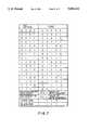
- FIG. 7is a chart to show an example of the data set in the conversion table of the encoding unit shown in FIG. 3;
- FIGS. 8 and 9show specific examples of images compacted by this invention device.
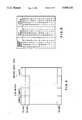
- FIG. 1is a block diagram to show the structure of an embodiment of the image compression device according to this invention.
- the image compression deviceessentially comprises a rearranging unit 3, an encoding unit 7, and an external unit 11 such as CPU which controls respective units.
- the input binary image data ADare compressed in image by the rearranging unit 3 and the encoding unit 7.
- Input buffers 1 and 2are provided at upstream positions of the rearranging unit 3 in order to temporarily store the binary image data AD.
- Switches SW1 and SW2are also provided at upstream positions of the rearranging device 3 so that the input binary image data AD may be written in either one of the input buffers 1 and 2 by switching a contact P1 or P2 of the switch SW1 or SW2.
- a binary image data ADis inputted to the rearranging device 3 by switching a contact P3 or P4 of the switch SW2 at a predetermined timing.
- the contacts P2 through P4 of the switches SW1 and SW2form a switching means 12.
- At upstream positions of the encoding unit 7are provided intermediate buffers 5 and 6 which temporarily store rearranged data.
- a switching meanswhich comprises switches SW3 and SW4 for switching a contact P5 or P6 of the switch SW3 at a predetermined timing in order to write in the rearranged data ND, and for switching contacts P7 or P8 of the switch SW4 in order to input the data ND at the encoding unit 7 when the writing is completed.
- output buffers 8 and 9Downstream of the encoding unit 7 are provided output buffers 8 and 9 for temporarily storing compressed image data GD and a switching means 14 which comprises switches SW5 and SW6 for switching a contact P9 or P10 of the switch SW5 and for switching a contact P11 or P12 of the switch SW6 so that the compressed image data GD may be read out.
- FIG. 2is a block diagram to show an embodiment of the rearranging unit 3 wherein the binary image data AD are read out for one sub-block from either the input buffer 1 or 2 according to an address outputted from an input buffer address generator 31.
- a sub-blockis obtained by partitioning the binary image data by a predetermined number of bits; for instance, the area defined by 40 bits/line ⁇ 10 lines shown in FIG. 4 is a sub-block.
- the binary image datais read out in units of a sub-block, and the read out binary image data is latched by a latch circuit 32.
- the binary image data of 8 bits thus latchedis converted and rearranged into data of 4 bits in accordance with a data conversion table 33 set in advance by the external unit 11, and written in either at the intermediate buffer 5 or 6.
- An address (address in the order of normal scanning) along the threshold matrix which is outputted from a sub-block address generator 34is converted in accordance with an address conversion table 35 set by the external unit 11 in advance to be used as the address for rearranging and writing in the converted data either at the intermediate buffer 5 or 6.
- the operations of these unitsare controlled by a rearranging circuit sequencer 36.
- FIG. 3is a block diagram to show an embodiment of the encoding unit 7 wherein the rearranged data ND is read out in units of 4 bits from intermediate buffer 5 or 6 in accordance with an address outputted from an address generator 71, and latched by a latch circuit 72.
- the rearranged data ND thus latchedare converted into 8 bits by a rearranging circuit sequencer 73 for the encoding unit 7, and judged.
- the address in the address generator 71is either increased or decreased based on the result of judgement.
- the rearranged and latched data NDencoded in accordance with a conversion table 74 set in advance by the external unit 11, and also encoded in accordance with the address from the address generator 71 which have been selected by a selecter 75.
- the encoded datais compressed by a bit compacting circuit 76 in the unit of the bit length generated from the rearranging circuit sequencer 73 for the encoder.
- a bit compacting circuit 76in the unit of the bit length generated from the rearranging circuit sequencer 73 for the encoder.
- the datais written in the output buffer 8 or 9 as a compressed image data GD.
- the rearranging circuit sequencer 73contains microprograms for each type of binary image data, and encoding to each type may be conducted using the same hardware.
- bits of the binary image data ADare rearranged irrespective of the order of the digits thereof in the data for dot images (for example, the binary image data of "1010” will be expressed as "0011") while in the data for line images, bits of the binary image data AD are arranged as they are.
- the address conversion table 35is written with data, for example as shown in FIG. 6A or 6B by the external unit 11.
- the data which have been converted by the data conversion table 33are rearranged in the unit of bytes into the rearranged data ND, in the order of the serial number (0, 1, 2, . . . , 99) of the address which has been converted by the address conversion table 35.
- the conversion table 74 of the encoding unit 7is written with data, for example as shown in FIG. 7, by the external unit 11.
- Rearranged data of 4 bitsare encoded by a first code of 5 bits comprising the rearranged data of 4 bits plus "0" at the leading edge. If "00000000” or “11111111” continues, they are encoded by writing in the value of a byte counter as a second code immediately after the series of "00000000” or “11111111” ends in a n bits (for instance 6).
- a series of "00000000” or "11111111”is also encoded as "100" or "101” as a third code which is added to the second code, thus creating a combined code. If all the remaining pixels are “0” or “1”, they are encoded by an end code "110" or "111” as a fourth code.
- FIGS. 8 and 9show specific examples of rearrangement and encoding described above.
- FIG. 8shows a case wherein the data shown in FIG. 6A is used while FIG. 9 a case wherein the data shown in FIG. 6B are used.
- the binary image data ADare rearranged in the unit of bytes in the order of the serial number shown in FIG. 6A or 6B to obtain the data ND, and encoded in accordance with the data shown in FIG. 7, and compressed into the image data GD.
- the rearrangement by the data shown in FIG. 6Ais a rearrangement in the ordinary scanning direction, but at the final stage, the image data can be compressed by 50%.
- the rearrangement by the data shown in FIG. 6Bpositions adjacent pixels side by side with due consideration of the continuity of images. In this case, image data can be compressed at the final stage to ca. 30%.
- the dataare not limited to those shown in FIG. 6B but may be those shown in FIGS. 10A through 10C.
- the image compression devicesince the image compression device according to this invention rearranges data with due consideration of the continuity of images according to the type of either line or dot image, and encodes them in the unit of plural bits, the device is applicable to any type of binary image data such as line or dot image for efficient data compression at high speed.
Landscapes
- Engineering & Computer Science (AREA)
- Multimedia (AREA)
- Signal Processing (AREA)
- Image Processing (AREA)
- Compression Of Band Width Or Redundancy In Fax (AREA)
Abstract
Description
Claims (10)
Applications Claiming Priority (2)
| Application Number | Priority Date | Filing Date | Title |
|---|---|---|---|
| JP63333837AJPH02179071A (en) | 1988-12-28 | 1988-12-28 | Picture compressor |
| JP63-333837 | 1988-12-28 |
Publications (1)
| Publication Number | Publication Date |
|---|---|
| US5046122Atrue US5046122A (en) | 1991-09-03 |
Family
ID=18270496
Family Applications (1)
| Application Number | Title | Priority Date | Filing Date |
|---|---|---|---|
| US07/458,463Expired - LifetimeUS5046122A (en) | 1988-12-28 | 1989-12-28 | Image compression device |
Country Status (2)
| Country | Link |
|---|---|
| US (1) | US5046122A (en) |
| JP (1) | JPH02179071A (en) |
Cited By (14)
| Publication number | Priority date | Publication date | Assignee | Title |
|---|---|---|---|---|
| US5229866A (en)* | 1990-10-10 | 1993-07-20 | Fuji Xerox Co., Ltd. | Image processing system for reducing wait time before image data transfer to an image output section |
| US5302949A (en)* | 1991-10-31 | 1994-04-12 | Sony Corporation | Signal encoding with reverse run length and variable length coding |
| US5335019A (en)* | 1993-01-14 | 1994-08-02 | Sony Electronics, Inc. | Digital video data quantization error detection as applied to intelligent dynamic companding |
| US5341440A (en)* | 1991-07-12 | 1994-08-23 | Earl Joseph G | Method and apparatus for increasing information compressibility |
| US5450544A (en)* | 1992-06-19 | 1995-09-12 | Intel Corporation | Method and apparatus for data buffering and queue management of digital motion video signals |
| US5610657A (en)* | 1993-09-14 | 1997-03-11 | Envistech Inc. | Video compression using an iterative error data coding method |
| US5974179A (en)* | 1995-02-13 | 1999-10-26 | Integrated Device Technology, Inc. | Binary image data compression and decompression |
| US6094453A (en)* | 1996-10-11 | 2000-07-25 | Digital Accelerator Corporation | Digital data compression with quad-tree coding of header file |
| US6268809B1 (en)* | 1997-12-05 | 2001-07-31 | Kabushiki Kaisha Toshiba | Data compression method for efficiently compressing data based on data periodicity |
| US6301389B1 (en)* | 1995-02-03 | 2001-10-09 | U. S. Philips Corporation | Video image color encoding |
| WO2001077996A1 (en)* | 2000-04-11 | 2001-10-18 | International Business Machines Corporation | Enhanced compression of gray-level images |
| US8369967B2 (en) | 1999-02-01 | 2013-02-05 | Hoffberg Steven M | Alarm system controller and a method for controlling an alarm system |
| US8892495B2 (en) | 1991-12-23 | 2014-11-18 | Blanding Hovenweep, Llc | Adaptive pattern recognition based controller apparatus and method and human-interface therefore |
| US10361802B1 (en) | 1999-02-01 | 2019-07-23 | Blanding Hovenweep, Llc | Adaptive pattern recognition based control system and method |
Citations (5)
| Publication number | Priority date | Publication date | Assignee | Title |
|---|---|---|---|---|
| US3624637A (en)* | 1970-04-29 | 1971-11-30 | Ibm | Digital code to digital code conversions |
| US3902008A (en)* | 1972-10-04 | 1975-08-26 | Ricoh Kk | Data transmission system |
| US4301479A (en)* | 1978-09-18 | 1981-11-17 | Hitachi, Ltd. | Signal processing system of facsimile |
| US4626829A (en)* | 1985-08-19 | 1986-12-02 | Intelligent Storage Inc. | Data compression using run length encoding and statistical encoding |
| US4757552A (en)* | 1984-10-24 | 1988-07-12 | International Business Machines Corporation | Method for processing binary image data |
- 1988
- 1988-12-28JPJP63333837Apatent/JPH02179071A/enactivePending
- 1989
- 1989-12-28USUS07/458,463patent/US5046122A/ennot_activeExpired - Lifetime
Patent Citations (5)
| Publication number | Priority date | Publication date | Assignee | Title |
|---|---|---|---|---|
| US3624637A (en)* | 1970-04-29 | 1971-11-30 | Ibm | Digital code to digital code conversions |
| US3902008A (en)* | 1972-10-04 | 1975-08-26 | Ricoh Kk | Data transmission system |
| US4301479A (en)* | 1978-09-18 | 1981-11-17 | Hitachi, Ltd. | Signal processing system of facsimile |
| US4757552A (en)* | 1984-10-24 | 1988-07-12 | International Business Machines Corporation | Method for processing binary image data |
| US4626829A (en)* | 1985-08-19 | 1986-12-02 | Intelligent Storage Inc. | Data compression using run length encoding and statistical encoding |
Cited By (17)
| Publication number | Priority date | Publication date | Assignee | Title |
|---|---|---|---|---|
| US5229866A (en)* | 1990-10-10 | 1993-07-20 | Fuji Xerox Co., Ltd. | Image processing system for reducing wait time before image data transfer to an image output section |
| US5341440A (en)* | 1991-07-12 | 1994-08-23 | Earl Joseph G | Method and apparatus for increasing information compressibility |
| US5302949A (en)* | 1991-10-31 | 1994-04-12 | Sony Corporation | Signal encoding with reverse run length and variable length coding |
| US8892495B2 (en) | 1991-12-23 | 2014-11-18 | Blanding Hovenweep, Llc | Adaptive pattern recognition based controller apparatus and method and human-interface therefore |
| US5450544A (en)* | 1992-06-19 | 1995-09-12 | Intel Corporation | Method and apparatus for data buffering and queue management of digital motion video signals |
| US5335019A (en)* | 1993-01-14 | 1994-08-02 | Sony Electronics, Inc. | Digital video data quantization error detection as applied to intelligent dynamic companding |
| US5610657A (en)* | 1993-09-14 | 1997-03-11 | Envistech Inc. | Video compression using an iterative error data coding method |
| US6301389B1 (en)* | 1995-02-03 | 2001-10-09 | U. S. Philips Corporation | Video image color encoding |
| US5974179A (en)* | 1995-02-13 | 1999-10-26 | Integrated Device Technology, Inc. | Binary image data compression and decompression |
| US6094453A (en)* | 1996-10-11 | 2000-07-25 | Digital Accelerator Corporation | Digital data compression with quad-tree coding of header file |
| US6268809B1 (en)* | 1997-12-05 | 2001-07-31 | Kabushiki Kaisha Toshiba | Data compression method for efficiently compressing data based on data periodicity |
| US8369967B2 (en) | 1999-02-01 | 2013-02-05 | Hoffberg Steven M | Alarm system controller and a method for controlling an alarm system |
| US8583263B2 (en) | 1999-02-01 | 2013-11-12 | Steven M. Hoffberg | Internet appliance system and method |
| US9535563B2 (en) | 1999-02-01 | 2017-01-03 | Blanding Hovenweep, Llc | Internet appliance system and method |
| US10361802B1 (en) | 1999-02-01 | 2019-07-23 | Blanding Hovenweep, Llc | Adaptive pattern recognition based control system and method |
| US6522784B1 (en) | 2000-04-11 | 2003-02-18 | International Business Machines Corporation | Enhanced compression of gray-level images |
| WO2001077996A1 (en)* | 2000-04-11 | 2001-10-18 | International Business Machines Corporation | Enhanced compression of gray-level images |
Also Published As
| Publication number | Publication date |
|---|---|
| JPH02179071A (en) | 1990-07-12 |
Similar Documents
| Publication | Publication Date | Title |
|---|---|---|
| US5046122A (en) | Image compression device | |
| US4971407A (en) | Two stage run and string data compressor providing doubly compressed output | |
| KR100331351B1 (en) | Method and apparatus for compressing and decompressing image data | |
| US5627534A (en) | Dual stage compression of bit mapped image data using refined run length and LZ compression | |
| JPS6223504B2 (en) | ||
| US5751860A (en) | Method for compressing and decompressing digital image data | |
| US4943869A (en) | Compression method for dot image data | |
| US3935379A (en) | Method of and system for adaptive run length encoding of image representing digital information | |
| US5694125A (en) | Sliding window with big gap data compression system | |
| US5701125A (en) | Method for compression of data using single pass LZSS and run-length encoding | |
| GB2175769A (en) | Processing image data | |
| JP3231800B2 (en) | Image encoding apparatus and image encoding method | |
| JPH0789618B2 (en) | Image coding method | |
| JPH05151349A (en) | Image data compression method and encoding circuit | |
| JP2812064B2 (en) | Image processing device | |
| US5745603A (en) | Two dimensional context model obtained without a line buffer for arithmetic coding | |
| JPH02179072A (en) | Compression method for binary picture data | |
| KR100195095B1 (en) | Image signal encoding apparatus | |
| JP2800250B2 (en) | Data compression method | |
| JP2708252B2 (en) | Image data compression method | |
| JPH02218224A (en) | Data transferring method | |
| EP0450014B1 (en) | Apparatus and method for image data transposition and compression/decompression | |
| JPH0789621B2 (en) | Encoder | |
| EP0652670A1 (en) | Image encoding apparatus and method | |
| JP4526209B2 (en) | Variable length code decompression method and apparatus, and variable length code compression and decompression method and apparatus |
Legal Events
| Date | Code | Title | Description |
|---|---|---|---|
| AS | Assignment | Owner name:FUJI PHOTO FILM CO., LTD., JAPAN Free format text:ASSIGNMENT OF ASSIGNORS INTEREST.;ASSIGNORS:NAKAYA, DAISUKE;HORIKAWA, HIROSHI;REEL/FRAME:005207/0724 Effective date:19891206 | |
| STCF | Information on status: patent grant | Free format text:PATENTED CASE | |
| FEPP | Fee payment procedure | Free format text:PAYOR NUMBER ASSIGNED (ORIGINAL EVENT CODE: ASPN); ENTITY STATUS OF PATENT OWNER: LARGE ENTITY | |
| FPAY | Fee payment | Year of fee payment:4 | |
| FEPP | Fee payment procedure | Free format text:PAYER NUMBER DE-ASSIGNED (ORIGINAL EVENT CODE: RMPN); ENTITY STATUS OF PATENT OWNER: LARGE ENTITY Free format text:PAYOR NUMBER ASSIGNED (ORIGINAL EVENT CODE: ASPN); ENTITY STATUS OF PATENT OWNER: LARGE ENTITY | |
| FPAY | Fee payment | Year of fee payment:8 | |
| FEPP | Fee payment procedure | Free format text:PAYER NUMBER DE-ASSIGNED (ORIGINAL EVENT CODE: RMPN); ENTITY STATUS OF PATENT OWNER: LARGE ENTITY Free format text:PAYOR NUMBER ASSIGNED (ORIGINAL EVENT CODE: ASPN); ENTITY STATUS OF PATENT OWNER: LARGE ENTITY | |
| FPAY | Fee payment | Year of fee payment:12 | |
| AS | Assignment | Owner name:FUJIFILM CORPORATION, JAPAN Free format text:ASSIGNMENT OF ASSIGNORS INTEREST;ASSIGNOR:FUJIFILM HOLDINGS CORPORATION (FORMERLY FUJI PHOTO FILM CO., LTD.);REEL/FRAME:018904/0001 Effective date:20070130 Owner name:FUJIFILM CORPORATION,JAPAN Free format text:ASSIGNMENT OF ASSIGNORS INTEREST;ASSIGNOR:FUJIFILM HOLDINGS CORPORATION (FORMERLY FUJI PHOTO FILM CO., LTD.);REEL/FRAME:018904/0001 Effective date:20070130 |