US5045645A - Digitizer system with passive pointer - Google Patents
Digitizer system with passive pointerDownload PDFInfo
- Publication number
- US5045645A US5045645AUS07/527,027US52702790AUS5045645AUS 5045645 AUS5045645 AUS 5045645AUS 52702790 AUS52702790 AUS 52702790AUS 5045645 AUS5045645 AUS 5045645A
- Authority
- US
- United States
- Prior art keywords
- frequency
- conductors
- grid
- driving
- driving signal
- Prior art date
- Legal status (The legal status is an assumption and is not a legal conclusion. Google has not performed a legal analysis and makes no representation as to the accuracy of the status listed.)
- Expired - Fee Related
Links
Images


Classifications
- G—PHYSICS
- G06—COMPUTING OR CALCULATING; COUNTING
- G06F—ELECTRIC DIGITAL DATA PROCESSING
- G06F3/00—Input arrangements for transferring data to be processed into a form capable of being handled by the computer; Output arrangements for transferring data from processing unit to output unit, e.g. interface arrangements
- G06F3/01—Input arrangements or combined input and output arrangements for interaction between user and computer
- G06F3/03—Arrangements for converting the position or the displacement of a member into a coded form
- G06F3/041—Digitisers, e.g. for touch screens or touch pads, characterised by the transducing means
- G06F3/046—Digitisers, e.g. for touch screens or touch pads, characterised by the transducing means by electromagnetic means
Definitions
- This inventionrelates to graphic digitizers, that is, systems for translating the physical position of a pointer relative to a grid of spaced conductors into electrical signals for use by a utilization device. More particularly, it relates to a digitizer system having a passive pointer, i.e., one that requires neither a connecting cord nor a battery.
- Digitizersare very useful for translating the position of a point on a plan or drawing into coordinates recognizable by a computer.
- the computercan make use of the position information in any number of useful ways.
- the digitizer position informationis relative to a grid of conductors incorporated into its work surface. It becomes, therefore, absolute with respect to the work surface and any plan or drawing mounted thereon in a designated orientation.
- the position informationis accurate enough not only to edit graphic displays, but also to control manufacturing processes according to scale drawings placed on the work surface, and to control navigation of air and water craft according to charts.
- a number of well known digitizer systemsmake use of a movable coil and a work surface defined by a receiving grid of conductors.
- the coilmay be disposed within the tip of a pen-shaped instrument so that the pen point accurately locates the effective coil center.
- the coilmay surround a transparent disc with a set of cross hairs etched thereon to mark the coil center in what is known as a cursor.
- the receiving gridnormally comprises a set of parallel conductors uniformly spaced along the work surface in what may be called the x direction and another set similarly disposed along the work surface in the orthogonal y direction.
- An oscillatorapplies an ac signal of predetermined frequency and amplitude to the coil, which is inductively coupled to the conductors of the grid.
- ac electrical signalsare induced in the grid conductors at a magnitude and phase that depend on the location of the coil relative to the conductors.
- the signals induced in the conductorswill have a magnitude that varies from zero at the coil center to a maximum at the coil periphery and tapering off beyond.
- the phase of the signals induced in conductors at one side of the coilwill be the opposite of (180 degrees displaced from) that of signals induced in conductors at the other side.
- the conductors in each setare accessed in a predetermined order through the use of multiplexer circuitry to couple the induced signals to detection circuitry.
- the detection circuitrycoarsely locates the pointer between them. The exact position of the pointer between the indicated conductors may then be determined by the relative magnitudes of induced signal in the adjacent conductors.
- a cableconnects the ac signal to the coil, tethering the pointer to the base electronics associated with the work surface. Additional wires in the cable connected to switches on the pointer allow the operator to supply additional information to the base electronics. For example, the information that the coil is at a point where coordinates are desired can be so signalled.
- Such cablesrestrict free movement of the pointer across the digitizer work surface.
- the oscillatormay be located in the pointer together with a battery for power. In this case, the switches on the pointer can cause phase shifts in the oscillator signal that will be recognized by the base electronics. Such batteries, however, tend to be heavy and bulky, or else expensive and short-lived.
- a digitizing system that requires neither cable nor batteryis disclosed in U.S. Pat. No. 4,878,553 which issued on Nov. 7, 1989 to T. Yamanami et al.
- an ac signalis first applied to a selected receiving grid conductor.
- a tuned circuitcomprising a coil and a capacitor located in the pointer is inductively excited by the ac signal on the selected conductor to resonate at the same frequency.
- the ac signalis then removed from the selected conductor, and, after a sufficient time interval for confusing transients and clutter to subside, the conductor is connected to detection circuitry.
- the tuned circuit in the pointercontinues to ring, and it serves as the ac source for detection as in the prior art.
- An object of our inventionis to provide a digitizer system having an untethered passive pointer that can make use of a full-time driving signal.
- a digitizer system embodied in accordance with the present inventionutilizes a composite driving signal that comprises first and second frequency components.
- a movable pointercomprises a first tuned circuit, inductively coupled to the composite driving signal and responsive to the first frequency component, and a second tuned circuit responsive to the second frequency component of the composite driving signal and inductively coupled to a grid of spaced conductors. The signals coupled in selected conductors of the grid are detected to determine the location of the pointer relative to the conductors.
- the composite driving signalmay comprise a carrier frequency, f 1 , modulated by a lower frequency, f 2 .
- a pickup coil in the pointer, inductively coupled to the driving signalmay be part of the first tuned circuit tuned to resonate substantially at frequency f 1 .
- a driving coil in the pointer, inductively coupled to the receiving gridmay be part of the second tuned circuit tuned to resonate substantially at frequency f 2 .
- Diode meansmay be connected between the two tuned circuits to couple energy from the first tuned circuit to drive the second tuned circuit and the driving coil.
- the composite driving signalmay be applied to selected conductors of a separate driving grid. Alternatively, the driving signal may be applied to selected receiving grid conductors of the set spaced in the y direction while the digitizer is determining the location of the pointer along the x direction, and vice versa.
- FIG. 1is a block diagram of a particularly useful embodiment of the invention
- FIG. 2is a circuit diagram of a pointer circuit useful in practicing the invention
- FIGS. 3A through 3Fare a series of waveforms useful in explaining the operation of the invention.
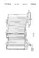
- FIG. 4is a pictorial diagram of a driving grid arrangement useful in practicing the invention.
- FIG. 5is a block diagram showing an alternative arrangement in place of the separate driving grid shown in FIG. 1.
- the position of an untethered and passive pointer 10, in relation to a receiving grid 12is determined by a process under the control of a controller 14.
- An oscillator 16is connected to controller 14 to provide clock signals thereto, and to a frequency divider 18.
- Divider 18may have three outputs connected via bandpass filtering apparatus 19 to a modulator 20.
- the output of the modulatormay be connected through a bandpass filter 21 and an amplifier 22 to the signal input of a switching multiplexer 24.
- Multiplexer 24may have an address input connected to controller 14 via an address bus 26 and a series of outputs 28 connected to individual conductors of a driving grid 30.
- Receiving grid 12may advantageously have a series of parallel conductors 32 distributed in an x-direction and a series of parallel conductors 34 distributed in a y-direction, orthogonal to the x-direction.
- Conductors 32 and 34are connected to individual inputs of a switching multiplexer 36.
- An address bus 38connects controller 14 to the address inputs of multiplexer 36.
- the output of receiving multiplexer 36may be connected via a bandpass amplifier 37 to one input of a phase detector 39 and to one input of a synchronous demodulator 40.
- a second input of detector 39 and a second input of demodulator 40are connected to modulator 20.
- the output of phase detector 39may be connected to controller 14.
- the output of demodulator 40may be connected to the signal input of a voltage-to-frequency converter 42, which may have a control input connected to controller 14. Finally, the output of converter 42 may be connected to a counter 44 to produce a numerical output, which is fed back to controller 14.
- the operation of the circuit of FIG. 1may be described as follows.
- the signal from clock oscillator 16may be divided by two separate numbers in divider 18 to produce a high frequency f 1 , and a much lower frequency f 2 .
- the third frequency f 3 output from divider 18is not needed in all embodiments and will be referred to later.
- the two frequenciesmay be bandpass filtered and modulated together.
- the resulting classical amplitude modulated (AM) signalis shown in FIG. 3A, in which f 1 is the carrier frequency and f 2 the envelope frequency.
- the modulated signalis filtered to eliminate the f 2 component, amplified to an appropriate level and applied to the signal input of multiplexer 24.
- Pointer 10is particularly adapted to make use of the modulated driving signal.
- the electrical circuit of pointer 10includes a first tuned circuit 50 and a second tuned circuit 52.
- Circuit 50may include a coil 54 and a parallel capacitor 56. The combination is tuned to resonate at the carrier frequency, f 1 .
- Tuned circuit 52may include the parallel combination of a coil 58 and a capacitor 60.
- a pair of diodes 66 and 68may connect respective ends of coil 54 with one end of coil 52; the center of coil 54 is connected to the other end of coil 52.
- Circuit 50is tuned to pick up the maximum energy at frequency f 1 from the modulated signal that is applied selectively to conductors of driving grid 30. It therefore mimics the waveform of FIG. 3A.
- the diodesprovide full wave rectification of the signal to produce the waveform of FIG. 3B.
- a single diodecould be used to provide half wave rectification in the manner of typical AM signal detection.
- the full wave versionis preferred here to maximize the power transfer.
- Tuned circuit 52is tuned to resonate at frequency f 2 . Since this is the modulating envelope frequency of the signal induced in circuit 50 and applied to circuit 52 through the full wave rectifying diodes 66 and 68, it produces a strong signal in circuit 52, as shown in FIG. 3C, for inductive coupling to the conductors of receiving grid 12.
- the remainder of the circuit of the embodiment of FIG. 1may be any of a number of known digitizer detecting circuits.
- the detection circuitry shown, with the exception of phase detector 39,is similar to that described in U.S. Pat. No. 4,734,546 to Waldo L. Landmeier, the disclosure of which is incorporated herein by reference.
- An individual x conductor of the receive grid 12is connected to amplifier 37 by multiplexer 36 as addressed over bus 38 by controller 14.
- the bandpass amplifierprovides the proper operating signal levels for the system and filters out noise and other unwanted signal components.
- the output of amplifier circuit 37is applied to synchronous demodulator 40, which converts the ac signal to a dc signal.
- the dc signalhas an amplitude that is proportional to the amplitude of the ac signal applied to the input of amplifier 37 and a polarity that corresponds to that signal's phase.
- the output of synchronous demodulator 40is applied to an analog-to-digital converter.
- One such effective A/D convertercomprises voltage-to-frequency converter 42 and counter 44.
- the converter 42converts the dc signal out of demodulator 40 into a variable frequency signal, the frequency of which deviates from a zero-signal frequency by an amount proportional to the dc signal's magnitude and in a direction corresponding to its polarity.
- Counter 44counts cycles of the variable frequency signal over a fixed period of time to produce and report to controller 14 a digital number that, when subtracted from the zero-signal count, reflects the magnitude and phase of the ac signal induced in the selected x conductor of receiving grid 12.
- the phase of the signal detected on the selected x conductorindicates whether the pointer 10 is to the right or to the left of the selected conductor. Another x conductor is then selected and the voltage and phase of the induced signal on it are determined. Additional samplings are taken in the same fashion until the controller 14 ascertains that the pointer 10 is located between two adjacent x conductors (i.e., the phase of the signal on one of the adjacent conductors is 180° displaced from the phase of the signal on the other adjacent conductor). The digital numbers that represent the amplitude values of voltage detected on these two adjacent conductors are then used in a ratio to determine the precise location of the pointer between the adjacent conductors. The pointer location with respect to the y conductors may then be determined in a similar fashion, with the modulated driving signal still energizing the same driving grid conductor.
- Modulator 20need not necessarily be a sine wave modulator, nor produce the classic AM modulation waveform shown in FIG. 3A.
- modulator 20may be a simple AND gate with f 1 and f 2 inputs. It will then generate the equally satisfactory driving waveform shown in FIG. 3D by merely gating frequency f 1 on and off at the f 2 rate.
- divider 18produces a third frequency output f 3 .
- Modulator 20switches at the f 2 rate between two higher frequencies, f 1 and f 3 , to generate the signal shown in FIG. 3E.
- a suitable gating arrangement to produce this frequency shifted FM driving signalcan easily be chosen by a designer of ordinary skill.
- pick-up tuned circuit 50 of the pointerwill respond with a waveform similar to that shown in FIG. 3F.
- This driving waveformhas an advantage over that of FIG. 3D in that it tends to speed up the reaction of driving tuned circuit 52 to produce a higher output.
- frequency f 2should not appear in the spectrum of the driving signal. As is well known in the art, this may require bandpass filtering and substantial attention to the linearity of the amplifier.
- a high frequency f 1 of 2.7 MHz modulated by a low frequency f 2 of 230 KHzmake a usable AM signal for driving the digitizer of this invention.
- the frequency f 3may be 1800 KHz.
- each driving grid conductor, 80-83forms several driving grid coils spaced along the digitizer work surface.
- Conductor 80forms coils 87, 88 and 89. It will be understood that each of the coils may be a multiturn coil, although, in order to keep the drawing readable, only coils 87 and 88 are drawn with multiple turns.
- the number of turnsmay be many more than the two turns shown, as dictated by the needs of the circuit.
- Conductor 81therefore, forms coils 91, 92 and 93.
- the remaining conductorseach form spaced coils that overlap coils formed by other conductors.
- Switching multiplexer 124can therefore be a simple combination logic gating arrangement controlled by a two wire bus 26. Circuit designers can choose the number of turns per coil, the number of coils per conductor and the number of conductors that best suit their needs.
- Controller 14using the coarse location information, can then send the proper address to multiplexer 124 to maximize the driving signal at the pointer.
- the receiving circuitrycan thereafter determine the exact pointer location most effectively. There is, of course, no need to change the selected driving grid conductor for the subsequent location determination with respect to the receiving y grid.
- FIG. 5Another arrangement for the driving grid is shown in FIG. 5. According to this arrangement, no separate driving grid is needed; the idle one of the x and y receiving grids is driven by the modulated driving signal.
- Multiplexer 24is therefore replaced by a driving switch 224 that can connect the driving signal from amplifier 22 to any one of the conductors 232 of the x receiving grid or any one the conductors 234 of the y receiving grid. The selection is made by controller 14 over bus 226.
- the y conductorsare sequentially driven by the modulated driving signal, and the y conductor that produces the maximum response in the receiving circuitry is selected as the driving conductor.
- the optimum driving grid conductorwill be the same for all selected receiving conductors.
- the receiving x conductorsare then sequentially connected to the receiving circuitry in the usual manner to determine the pointer position relative thereto. In the subsequent process of determining the pointer position relative to the y conductors, there is no need to scan the x conductors with the driving signal for a maximum response.
- the x conductor nearest the pointeris already known and may be selected by controller 14.
- Additional reactive circuitsmay be connected into tuned circuit 52 by individual switches, as indicated by capacitor 62 and switch 64 in FIG. 2. Since circuit 52 is driven by the detected envelope of the modulated driving signal, the added reactance has little effect on the frequency at which the circuit operates. It does, however, produce an immediate phase shift, which can be detected and reported to controller 14 by a phase detector circuit 39 connected as shown in FIG. 1. Such switch-induced phase shifts and the range of phase detector can be limited to relatively small values. Controller 14 then can ignore positional information received during a switch-induced phase shift. Such phase shifts can therefore provide the signaling function of the hard wired switches of the tethered pointers in the prior art.
Landscapes
- Engineering & Computer Science (AREA)
- Physics & Mathematics (AREA)
- General Engineering & Computer Science (AREA)
- Theoretical Computer Science (AREA)
- Electromagnetism (AREA)
- Human Computer Interaction (AREA)
- General Physics & Mathematics (AREA)
- Transmission And Conversion Of Sensor Element Output (AREA)
Abstract
Description
Claims (28)
Priority Applications (1)
| Application Number | Priority Date | Filing Date | Title |
|---|---|---|---|
| US07/527,027US5045645A (en) | 1990-05-22 | 1990-05-22 | Digitizer system with passive pointer |
Applications Claiming Priority (1)
| Application Number | Priority Date | Filing Date | Title |
|---|---|---|---|
| US07/527,027US5045645A (en) | 1990-05-22 | 1990-05-22 | Digitizer system with passive pointer |
Publications (1)
| Publication Number | Publication Date |
|---|---|
| US5045645Atrue US5045645A (en) | 1991-09-03 |
Family
ID=24099803
Family Applications (1)
| Application Number | Title | Priority Date | Filing Date |
|---|---|---|---|
| US07/527,027Expired - Fee RelatedUS5045645A (en) | 1990-05-22 | 1990-05-22 | Digitizer system with passive pointer |
Country Status (1)
| Country | Link |
|---|---|
| US (1) | US5045645A (en) |
Cited By (30)
| Publication number | Priority date | Publication date | Assignee | Title |
|---|---|---|---|---|
| US5160813A (en)* | 1991-09-27 | 1992-11-03 | Calcomp Inc. | Cordless digitizer local conductor phase reference system |
| EP0573136A1 (en)* | 1992-06-01 | 1993-12-08 | Summagraphics Corporation | Cordless digitizer with sync signal generator |
| GB2273778A (en)* | 1992-12-22 | 1994-06-29 | Tds Cad Graphics Limited | Cordless digitizer |
| DE4400946C1 (en)* | 1993-11-12 | 1995-03-30 | Mikron Ges Fuer Integrierte Mi | Wireless position detecting device |
| US5541371A (en)* | 1993-06-01 | 1996-07-30 | Holtek Microelectronics Inc. | Palpably controllable digital plate |
| US5557076A (en)* | 1993-11-12 | 1996-09-17 | Mikron Gesellschaft Fur | Cordless position detection apparatus |
| US5571997A (en)* | 1993-08-02 | 1996-11-05 | Kurta Corporation | Pressure sensitive pointing device for transmitting signals to a tablet |
| US5629499A (en)* | 1993-11-30 | 1997-05-13 | Hewlett-Packard Company | Electronic board to store and transfer information |
| US5714720A (en)* | 1994-09-15 | 1998-02-03 | Calcomp Inc. | High efficiency passive pointer digitizer system |
| US6002387A (en)* | 1994-12-22 | 1999-12-14 | Nokia Mobile Phones, Ltd. | System for transferring information between a pointer and a display interface |
| US6050490A (en)* | 1997-10-31 | 2000-04-18 | Hewlett-Packard Company | Handheld writing device and related data entry system |
| JP3273585B2 (en) | 1994-09-29 | 2002-04-08 | 株式会社ワコム | Digitizer and position detection method |
| US6396005B2 (en) | 1998-06-15 | 2002-05-28 | Rodgers Technology Center, Inc. | Method and apparatus for diminishing grid complexity in a tablet |
| US20040246230A1 (en)* | 2003-03-28 | 2004-12-09 | Yasuo Oda | Position detection system and position detector |
| US20050104865A1 (en)* | 2003-09-25 | 2005-05-19 | Yasuo Oda | Position detecting system and position detecting apparatus |
| US20060131658A1 (en)* | 2004-12-22 | 2006-06-22 | Dongbuanam Semiconductor Inc. | MOS device, CMOS device, and fabricating method thereof |
| US7133793B2 (en) | 2003-07-24 | 2006-11-07 | Synaptics (Uk) Limited | Magnetic calibration array |
| EP1607851A3 (en)* | 2004-06-18 | 2007-01-17 | Wacom Co., Ltd. | Position detecting device |
| US7406393B2 (en) | 2002-03-05 | 2008-07-29 | Synaptics (Uk) Limited | Position sensor |
| US7408838B1 (en) | 2007-01-22 | 2008-08-05 | Scale Master Technologies, Llc | Digitizing planimeter |
| US7511705B2 (en) | 2001-05-21 | 2009-03-31 | Synaptics (Uk) Limited | Position sensor |
| US20100033437A1 (en)* | 2008-02-13 | 2010-02-11 | Wacom Co., Ltd. | Position detecting device and position detecting method |
| CN1534307B (en)* | 2003-03-28 | 2010-05-05 | 株式会社华科姆 | Position detecting system and position detecting device |
| US7812268B2 (en) | 2003-08-26 | 2010-10-12 | Synaptics (Uk) Limited | Digitizer system |
| US7907130B2 (en) | 2002-06-05 | 2011-03-15 | Synaptics (Uk) Limited | Signal transfer method and apparatus |
| US8570028B2 (en) | 2007-05-10 | 2013-10-29 | Cambridge Integrated Circuits Limited | Transducer for a position sensor |
| US20140084907A1 (en)* | 2012-09-27 | 2014-03-27 | Wacom Co., Ltd. | Electromagnetic induction position detection sensor |
| TWI450134B (en)* | 2011-03-23 | 2014-08-21 | Kye Systems Corp | Non-contact inputting device of computer peripheral and methods for the same |
| US9410791B2 (en) | 2010-12-24 | 2016-08-09 | Cambridge Integrated Circuits Limited | Position sensing transducer |
| US9470505B2 (en) | 2012-06-13 | 2016-10-18 | Cambridge Integrated Circuits Limited | Position sensing transducer |
Citations (9)
| Publication number | Priority date | Publication date | Assignee | Title |
|---|---|---|---|---|
| US3689885A (en)* | 1970-09-15 | 1972-09-05 | Transitag Corp | Inductively coupled passive responder and interrogator unit having multidimension electromagnetic field capabilities |
| US4023167A (en)* | 1975-06-16 | 1977-05-10 | Wahlstrom Sven E | Radio frequency detection system and method for passive resonance circuits |
| US4423286A (en)* | 1982-07-21 | 1983-12-27 | Talos Systems, Inc. | Apparatus and method for determining the position of a driven coil within a grid of spaced conductors |
| US4697050A (en)* | 1985-07-09 | 1987-09-29 | Alain Farel | Device for digitalizing graphical data |
| US4704501A (en)* | 1984-12-28 | 1987-11-03 | Wacom Co., Ltd. | Position detecting device |
| US4734546A (en)* | 1987-03-16 | 1988-03-29 | Calcomp, Inc. | Digitizer system with loopback conductor grid |
| US4786765A (en)* | 1986-07-23 | 1988-11-22 | Wacom Co., Ltd. | Coordinates input system |
| US4878553A (en)* | 1986-09-12 | 1989-11-07 | Wacom Co., Ltd. | Position detecting apparatus |
| US4902858A (en)* | 1986-09-08 | 1990-02-20 | Wacom Co., Ltd. | Coordinates input apparatus |
- 1990
- 1990-05-22USUS07/527,027patent/US5045645A/ennot_activeExpired - Fee Related
Patent Citations (11)
| Publication number | Priority date | Publication date | Assignee | Title |
|---|---|---|---|---|
| US3689885A (en)* | 1970-09-15 | 1972-09-05 | Transitag Corp | Inductively coupled passive responder and interrogator unit having multidimension electromagnetic field capabilities |
| US4023167A (en)* | 1975-06-16 | 1977-05-10 | Wahlstrom Sven E | Radio frequency detection system and method for passive resonance circuits |
| US4423286A (en)* | 1982-07-21 | 1983-12-27 | Talos Systems, Inc. | Apparatus and method for determining the position of a driven coil within a grid of spaced conductors |
| US4423286B1 (en)* | 1982-07-21 | 1993-05-25 | Calcomp Inc | |
| US4704501A (en)* | 1984-12-28 | 1987-11-03 | Wacom Co., Ltd. | Position detecting device |
| US4697050A (en)* | 1985-07-09 | 1987-09-29 | Alain Farel | Device for digitalizing graphical data |
| US4786765A (en)* | 1986-07-23 | 1988-11-22 | Wacom Co., Ltd. | Coordinates input system |
| US4902858A (en)* | 1986-09-08 | 1990-02-20 | Wacom Co., Ltd. | Coordinates input apparatus |
| US4878553A (en)* | 1986-09-12 | 1989-11-07 | Wacom Co., Ltd. | Position detecting apparatus |
| US4878553B1 (en)* | 1986-09-12 | 1997-09-16 | Wacom Co Ltd | Position detecting apparatus |
| US4734546A (en)* | 1987-03-16 | 1988-03-29 | Calcomp, Inc. | Digitizer system with loopback conductor grid |
Cited By (39)
| Publication number | Priority date | Publication date | Assignee | Title |
|---|---|---|---|---|
| US5160813A (en)* | 1991-09-27 | 1992-11-03 | Calcomp Inc. | Cordless digitizer local conductor phase reference system |
| EP0573136A1 (en)* | 1992-06-01 | 1993-12-08 | Summagraphics Corporation | Cordless digitizer with sync signal generator |
| GB2273778A (en)* | 1992-12-22 | 1994-06-29 | Tds Cad Graphics Limited | Cordless digitizer |
| EP0607694A1 (en)* | 1992-12-22 | 1994-07-27 | T.D.S. Cad-Graphics Ltd. | Cordless digitizer |
| US5541371A (en)* | 1993-06-01 | 1996-07-30 | Holtek Microelectronics Inc. | Palpably controllable digital plate |
| US5571997A (en)* | 1993-08-02 | 1996-11-05 | Kurta Corporation | Pressure sensitive pointing device for transmitting signals to a tablet |
| DE4400946C1 (en)* | 1993-11-12 | 1995-03-30 | Mikron Ges Fuer Integrierte Mi | Wireless position detecting device |
| US5557076A (en)* | 1993-11-12 | 1996-09-17 | Mikron Gesellschaft Fur | Cordless position detection apparatus |
| US5629499A (en)* | 1993-11-30 | 1997-05-13 | Hewlett-Packard Company | Electronic board to store and transfer information |
| US5714720A (en)* | 1994-09-15 | 1998-02-03 | Calcomp Inc. | High efficiency passive pointer digitizer system |
| JP3273585B2 (en) | 1994-09-29 | 2002-04-08 | 株式会社ワコム | Digitizer and position detection method |
| US6002387A (en)* | 1994-12-22 | 1999-12-14 | Nokia Mobile Phones, Ltd. | System for transferring information between a pointer and a display interface |
| US6050490A (en)* | 1997-10-31 | 2000-04-18 | Hewlett-Packard Company | Handheld writing device and related data entry system |
| US6396005B2 (en) | 1998-06-15 | 2002-05-28 | Rodgers Technology Center, Inc. | Method and apparatus for diminishing grid complexity in a tablet |
| US8243033B2 (en) | 2001-05-21 | 2012-08-14 | Synaptics (Uk) Limited | Position sensor |
| US7511705B2 (en) | 2001-05-21 | 2009-03-31 | Synaptics (Uk) Limited | Position sensor |
| US7406393B2 (en) | 2002-03-05 | 2008-07-29 | Synaptics (Uk) Limited | Position sensor |
| US7907130B2 (en) | 2002-06-05 | 2011-03-15 | Synaptics (Uk) Limited | Signal transfer method and apparatus |
| EP1462922A3 (en)* | 2003-03-28 | 2006-10-18 | Wacom Co., Ltd. | Position detection system and position detector |
| EP1462919A3 (en)* | 2003-03-28 | 2006-10-18 | Wacom Co., Ltd. | Position detection system and position detector |
| US20040246230A1 (en)* | 2003-03-28 | 2004-12-09 | Yasuo Oda | Position detection system and position detector |
| US7423629B2 (en) | 2003-03-28 | 2008-09-09 | Wacom Co., Ltd. | Position detection system and position detector |
| CN1534307B (en)* | 2003-03-28 | 2010-05-05 | 株式会社华科姆 | Position detecting system and position detecting device |
| US7133793B2 (en) | 2003-07-24 | 2006-11-07 | Synaptics (Uk) Limited | Magnetic calibration array |
| US8022317B2 (en) | 2003-08-26 | 2011-09-20 | Synaptics (Uk) Limited | Digitizer system |
| US7812268B2 (en) | 2003-08-26 | 2010-10-12 | Synaptics (Uk) Limited | Digitizer system |
| US20050104865A1 (en)* | 2003-09-25 | 2005-05-19 | Yasuo Oda | Position detecting system and position detecting apparatus |
| US7675507B2 (en) | 2003-09-25 | 2010-03-09 | Wacom Co., Ltd. | Position detecting system and position detecting apparatus |
| EP1607851A3 (en)* | 2004-06-18 | 2007-01-17 | Wacom Co., Ltd. | Position detecting device |
| US20060131658A1 (en)* | 2004-12-22 | 2006-06-22 | Dongbuanam Semiconductor Inc. | MOS device, CMOS device, and fabricating method thereof |
| US7408838B1 (en) | 2007-01-22 | 2008-08-05 | Scale Master Technologies, Llc | Digitizing planimeter |
| US8570028B2 (en) | 2007-05-10 | 2013-10-29 | Cambridge Integrated Circuits Limited | Transducer for a position sensor |
| US20100033437A1 (en)* | 2008-02-13 | 2010-02-11 | Wacom Co., Ltd. | Position detecting device and position detecting method |
| US8148652B2 (en)* | 2008-02-13 | 2012-04-03 | Wacom Co., Ltd. | Position detecting device and position detecting method |
| US9410791B2 (en) | 2010-12-24 | 2016-08-09 | Cambridge Integrated Circuits Limited | Position sensing transducer |
| TWI450134B (en)* | 2011-03-23 | 2014-08-21 | Kye Systems Corp | Non-contact inputting device of computer peripheral and methods for the same |
| US9470505B2 (en) | 2012-06-13 | 2016-10-18 | Cambridge Integrated Circuits Limited | Position sensing transducer |
| US20140084907A1 (en)* | 2012-09-27 | 2014-03-27 | Wacom Co., Ltd. | Electromagnetic induction position detection sensor |
| US9410824B2 (en)* | 2012-09-27 | 2016-08-09 | Wacom Co., Ltd. | Electromagnetic induction position detection sensor |
Similar Documents
| Publication | Publication Date | Title |
|---|---|---|
| US5045645A (en) | Digitizer system with passive pointer | |
| EP0607694B1 (en) | Cordless digitizer | |
| USRE34187E (en) | Coordinates input system | |
| CA1109538A (en) | Electronic coordinate position digitizing system | |
| KR960001648B1 (en) | Coordinate input device and its input pen | |
| US5124509A (en) | Digitizer with capacitive and inductive coupling | |
| US4848496A (en) | Coordinates input apparatus | |
| US4420682A (en) | Interactive map information exchange system | |
| KR930011886B1 (en) | Position detecting device | |
| US4956526A (en) | Digitizer having flat tablet with magnetic shield plate | |
| JPS633334B2 (en) | ||
| US7232068B2 (en) | Non-contact IC card reader/writer device, non-contact IC card, input device, and method of calculating location of non-contact IC card | |
| US4661656A (en) | Graphic tablet and method | |
| US4564835A (en) | Field-coupled pointing device | |
| US4334124A (en) | Floating coordinate system | |
| EP0602913A2 (en) | Method of use of multiple input styli in a system of multiple computers | |
| US4479032A (en) | Digitizing cursor and coordinate grid system | |
| US4473717A (en) | Digitizing system | |
| US5714720A (en) | High efficiency passive pointer digitizer system | |
| US5345044A (en) | Cordless digitizer using electromagnetic locating signals | |
| US5235142A (en) | Phase reference system for cordless looping digitizer | |
| JPS5599683A (en) | Coordinates reader | |
| SU1283817A1 (en) | Device for reading graphic information | |
| JPH062441U (en) | Digitizer | |
| JP2583500B2 (en) | Position detection device |
Legal Events
| Date | Code | Title | Description |
|---|---|---|---|
| AS | Assignment | Owner name:CALCOMP INC., CALIFORNIA Free format text:ASSIGNMENT OF ASSIGNORS INTEREST.;ASSIGNORS:HOENDERVOOGT, JASON;ABERNETHY, BRIAN;REEL/FRAME:005325/0098 Effective date:19900516 | |
| FPAY | Fee payment | Year of fee payment:4 | |
| AS | Assignment | Owner name:LOCKHEED MARTIN CORPORATION, MARYLAND Free format text:MERGER;ASSIGNOR:LOCKHEED CORPORATION;REEL/FRAME:009430/0915 Effective date:19960128 | |
| FPAY | Fee payment | Year of fee payment:8 | |
| AS | Assignment | Owner name:MCG FINANCE CORPORATION, VIRGINIA Free format text:SECURITY AGREEMENT;ASSIGNOR:GTCO CORPORATION;REEL/FRAME:010070/0137 Effective date:19990201 | |
| AS | Assignment | Owner name:FIRST UNION NATIONAL BANK, A CORPORATION OF NORTH Free format text:SECURITY INTEREST;ASSIGNOR:GTCO CORPORATION;REEL/FRAME:010514/0611 Effective date:19991227 | |
| AS | Assignment | Owner name:FIRST UNION NATIONAL BANK, VIRGINIA Free format text:SECURITY INTEREST;ASSIGNOR:GTCO CORPORATION;REEL/FRAME:010547/0449 Effective date:20000225 | |
| AS | Assignment | Owner name:GTCO CORPORATION, MARYLAND Free format text:RELEASE OF SECURITY INTEREST;ASSIGNOR:MCG FINANCE CORPORATION;REEL/FRAME:010696/0359 Effective date:20000112 | |
| FEPP | Fee payment procedure | Free format text:PAYOR NUMBER ASSIGNED (ORIGINAL EVENT CODE: ASPN); ENTITY STATUS OF PATENT OWNER: LARGE ENTITY | |
| REMI | Maintenance fee reminder mailed | ||
| LAPS | Lapse for failure to pay maintenance fees | ||
| STCH | Information on status: patent discontinuation | Free format text:PATENT EXPIRED DUE TO NONPAYMENT OF MAINTENANCE FEES UNDER 37 CFR 1.362 | |
| FP | Lapsed due to failure to pay maintenance fee | Effective date:20030903 | |
| AS | Assignment | Owner name:GTCO CORPORATION, TEXAS Free format text:RELEASE BY SECURED PARTY;ASSIGNOR:WACHOVIA BANK, NATIONAL ASSOCIATION, FKA FIRST UNION NATIONAL BANK;REEL/FRAME:020299/0585 Effective date:20071228 |