US5044133A - Skylight construction - Google Patents
Skylight constructionDownload PDFInfo
- Publication number
- US5044133A US5044133AUS07/446,077US44607789AUS5044133AUS 5044133 AUS5044133 AUS 5044133AUS 44607789 AUS44607789 AUS 44607789AUS 5044133 AUS5044133 AUS 5044133A
- Authority
- US
- United States
- Prior art keywords
- frame
- glazing
- opening
- securing
- gasket
- Prior art date
- Legal status (The legal status is an assumption and is not a legal conclusion. Google has not performed a legal analysis and makes no representation as to the accuracy of the status listed.)
- Expired - Lifetime
Links
- 238000010276constructionMethods0.000titleclaimsdescription85
- 238000007789sealingMethods0.000claimsabstractdescription50
- 239000000463materialSubstances0.000claimsabstractdescription18
- 229920003023plasticPolymers0.000claimsabstractdescription13
- 230000002093peripheral effectEffects0.000claimsabstractdescription4
- 210000005069earsAnatomy0.000claimsdescription13
- 229920002457flexible plasticPolymers0.000claims1
- 238000000034methodMethods0.000description8
- 238000013023gasketingMethods0.000description5
- XLYOFNOQVPJJNP-UHFFFAOYSA-NwaterSubstancesOXLYOFNOQVPJJNP-UHFFFAOYSA-N0.000description5
- 230000009471actionEffects0.000description4
- 238000009434installationMethods0.000description4
- 125000000484butyl groupChemical group[H]C([*])([H])C([H])([H])C([H])([H])C([H])([H])[H]0.000description3
- 238000005304joiningMethods0.000description3
- 239000007769metal materialSubstances0.000description3
- 229910052782aluminiumInorganic materials0.000description2
- XAGFODPZIPBFFR-UHFFFAOYSA-NaluminiumChemical compound[Al]XAGFODPZIPBFFR-UHFFFAOYSA-N0.000description2
- 238000009435building constructionMethods0.000description2
- 230000006872improvementEffects0.000description2
- 238000003780insertionMethods0.000description2
- 230000037431insertionEffects0.000description2
- 229910052751metalInorganic materials0.000description2
- 239000002184metalSubstances0.000description2
- 229920001021polysulfidePolymers0.000description2
- 239000005077polysulfideSubstances0.000description2
- 150000008117polysulfidesPolymers0.000description2
- 230000008569processEffects0.000description2
- 230000000717retained effectEffects0.000description2
- 125000006850spacer groupChemical group0.000description2
- 239000000853adhesiveSubstances0.000description1
- 230000001070adhesive effectEffects0.000description1
- 230000002411adverseEffects0.000description1
- 230000000903blocking effectEffects0.000description1
- 230000006835compressionEffects0.000description1
- 238000007906compressionMethods0.000description1
- 230000005494condensationEffects0.000description1
- 238000009833condensationMethods0.000description1
- 230000000694effectsEffects0.000description1
- 239000011521glassSubstances0.000description1
- 229910052602gypsumInorganic materials0.000description1
- 239000010440gypsumSubstances0.000description1
- 238000004519manufacturing processMethods0.000description1
- 230000004048modificationEffects0.000description1
- 238000012986modificationMethods0.000description1
- 230000007480spreadingEffects0.000description1
- 238000003892spreadingMethods0.000description1
- 239000002023woodSubstances0.000description1
Images


Classifications
- E—FIXED CONSTRUCTIONS
- E04—BUILDING
- E04D—ROOF COVERINGS; SKY-LIGHTS; GUTTERS; ROOF-WORKING TOOLS
- E04D13/00—Special arrangements or devices in connection with roof coverings; Protection against birds; Roof drainage ; Sky-lights
- E04D13/03—Sky-lights; Domes; Ventilating sky-lights
- E04D13/0305—Supports or connecting means for sky-lights of flat or domed shape
- E—FIXED CONSTRUCTIONS
- E04—BUILDING
- E04D—ROOF COVERINGS; SKY-LIGHTS; GUTTERS; ROOF-WORKING TOOLS
- E04D13/00—Special arrangements or devices in connection with roof coverings; Protection against birds; Roof drainage ; Sky-lights
- E04D13/03—Sky-lights; Domes; Ventilating sky-lights
- E04D13/035—Sky-lights; Domes; Ventilating sky-lights characterised by having movable parts
- E04D13/0351—Sky-lights; Domes; Ventilating sky-lights characterised by having movable parts the parts pivoting about a fixed axis
- E04D13/0354—Sky-lights; Domes; Ventilating sky-lights characterised by having movable parts the parts pivoting about a fixed axis the parts being flat
- E—FIXED CONSTRUCTIONS
- E04—BUILDING
- E04D—ROOF COVERINGS; SKY-LIGHTS; GUTTERS; ROOF-WORKING TOOLS
- E04D13/00—Special arrangements or devices in connection with roof coverings; Protection against birds; Roof drainage ; Sky-lights
- E04D13/14—Junctions of roof sheathings to chimneys or other parts extending above the roof
Definitions
- the present inventionrelates in general to an improved skylight construction and is concerned, more particularly, with an improved skylight construction preferably formed of a coextruded plastic material, thus adapting itself to simplified manufacture and having improved temperature resistant and weathering properties. Even more particularly, the present invention pertains to an improved gasket construction for a skylight, improvements in the skylight construction relating to the cushioning of the glazing, an improved gasket construction for the skylight which is particular characterized by improved weather and air tightness, and improved securing means for securing the skylight to a building.
- a skylight constructionis shown, by way of example, in U.S. Pat. No. 4,449,340, granted May 22, 1984 and owned by the present assignee herein.
- This skylight constructionis of plastic, including a frame that is comprised of a base frame and an operating leaf frame.
- a retainerthat may be constructed of a lightweight metal material is typically employed for holding the glazing to the curb frame. Gasketing is typically provided between the glazing and the frame as well as between the frame components.
- a securing clipis employed for securing the skylight curb frame to the building.
- the securing clipalthough engaging with the skylight curb frame, does not positively interlock therewith, and thus the securing clip may not be totally effective in the proper securing, as well as the positioning, of the skylight, particularly in proper orientation relative to the building opening. Accordingly, it is an object of the present invention to provide an improved securing clip for use with a skylight and, in particular, with the skylight curb frame, and furthermore, in particular, with a skylight curb frame made of a plastic material such as PVC.
- Another object of the present inventionis to provide an improved securing clip that is adapted to engage with a lower channel in the curb frame and that is furthermore adapted to provide positive interlocking between the securing clip and the curb frame.
- Another object of the present inventionto provide an improvement in skylight constructions in which cushioning is provided, essentially between the securing fastener associated with the retainer and the glazing or edge of the dome construction.
- Another object of the present inventionis to provide a new and improved skylight construction, particularly as it pertains to the use of a glazing cushioning member that provides a somewhat resilient surface for contact with the edge of the glazing and disposed intermediate the glazing and securing fastener or bolt.
- a further object of the present inventionis to provide a skylight construction as described in the foregoing objects, and in which the glazing cushioning member is constructed to receive the securing fastener therethrough for positioning thereof.
- Still another object of the present inventionis to provide an improved skylight construction in which the glazing cushioning member is constructed for snap fit engagement with the retainer.
- Another object of the present inventionis to provide an improved skylight construction, as set forth in the preceding objects, and wherein the glazing cushioning member furthermore functions to control the amount of tightening of the retainer against the glazing, so that the glazing is properly retained and held in place but not over-tightened.
- Another object of the present inventionto provide an improved gasket construction that is adapted to alleviate leakage problems that may occur through the usual gasketing employed in a skylight.
- Another object of the present inventionis to provide an improved skylight construction, and in particular a skylight construction having an improved gasket arrangement that assists in blockage and diversion of water, particularly at the top side of the skylight, and particularly under conditions of intense streams of water directed at the skylight, as might occur in a torrential downpour.
- Still another object of the present inventionis to provide an improved skylight construction having a water blocking and diverting gasket, also referred to herein as a header gasket, preferably coupled between the skylight retainer and curb frame, and preferably constructed for interlocking respectively therebetween.
- a water blocking and diverting gasketalso referred to herein as a header gasket
- a further object of the present inventionis to provide an improved sealing gasket for a skylight which is configured so as to provide proper sealing for both the application in which it is adapted to seal between curb frame sections as well as the application in which it is adapted to seal between the curb frame and covering or glazing.
- Still another object of the present inventionis to provide an improved skylight construction having an improved sealing gasket arrangement, and one which in particular provides multiple area sealing contact.
- a skylight constructionadapted to be fitted into an opening in a building such as either a commercial building or a residential building.
- the skylight constructioncomprises a frame means that is of plastic construction, such as constructed of extruded PVC.
- the frame means or curb frameextends about the opening and includes means for the securing thereof about the opening.
- the skylight constructionalso includes a translucent or transparent means covering the opening and extending at its edges to overlie the curb frame.
- the covering meansmay comprise one or more glazing panels, or may also be in the form of one or more plastic domes.
- a retainerextends about the periphery of the skylight for holding the glazing on the curb frame.
- the curb frameis comprised of a base frame and an operating leaf frame overlying the base frame.
- the curb frameis constructed of a rigid plastic profile having high temperature resistant properties and having integral therewith and coextruded therewith a flexible sealing flange.
- a glazing cushioning memberassociated with the skylight construction is a glazing cushioning member, that preferably snap-fits with the top leg of the retainer and has a passage in alignment with the hole through which the securing fastener for the retainer passes.
- the retainerhas associated therewith a plurality of fasteners usually in the form of securing bolts and likewise also preferably has associated therewith a plurality of glazing cushioning members disposed about the periphery of the glazing.
- the glazing cushioning memberincludes a body adapted to be disposed between the top leg of the retainer and the top of the curb frame, and a somewhat resilient cushioning piece held by the body and disposed in facing relationship to the edge of the glazing.
- the height of the body of the glazing cushioning memberis constructed so that when the securing bolt is tightened down, the body controls the spacing between the retainer and the curb frame so as to provide the proper pressure by the retainer on the glazing.
- a header gasketis provided and may be disposed only at the top side of the skylight as installed on a slanted roof.
- the header gaskethas a foldable center section and interlocking ends adapted to interlock, respectively, with the curb frame and retainer.
- the foldable section of the gasketenables the gasket to maintain its position in an operable skylight construction even when the skylight is opened and closed.
- the header gasketseals and assists in diverting water away from the skylight and prevents torrents of water from entering inside of the retainer and causing internal leakage at or about the skylight curb frame.
- an improved sealing gasketis provided, and in particular a sealing gasket that is integral with and coextruded with the curb frame.
- the improved gasket constructionprovides for multiple are sealing contact.
- the gaskethas a centrally disposed contact area as well as a pair of side disposed contact areas and is of generally tubular cross section.
- the gasketis adapted for providing a sealing between a base curb frame section and a overlying operative curb frame section.
- the same gasket constructionis useable for providing a sealing between the curb frame and the glazing.
- an improved securing clipis provided that is adapted to provide a positive interlocking between the curb frame and the securing clip for proper positioning and securing of the skylight curb frame about the building opening.
- the curb framehas a lower channel that receives the securing clip and in the lower channel there is defined in the curb frame a hook piece that engages with the channel in the securing clip so that once the securing clip is fully engaged in the curb frame channel then the securing clip is positively interlocked with the curb frame, thereby alleviating any positioning problems, and thereby ensuring that there will not be any slippage between the securing clip and the curb frame.
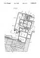
- FIG. 1is a perspective view, partially cut away, and illustrating a skylight construction in accordance with the present invention
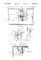
- FIG. 2is a cross-sectional view taken along line 2--2 of FIG. 1 and showing further cross-sectional details of the skylight construction;
- FIG. 3is a fragmentary plan view of the skylight construction at a securing bolt and partially cut away to show further details of the glazing cushioning member;
- FIG. 4is a perspective view showing the components of the glazing cushioning member.
- FIG. 5is a cross-sectional view showing the manner in which the glazing cushioning member is snap-fitted into the retainer.
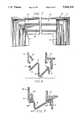
- FIG. 6is a cross-sectional view similar to the cross-sectional view of FIG. 2 but illustrating the skylight in an opened position;
- FIG. 7is a cross-sectional view taken along line 4--4 of FIG. 2;
- FIG. 8separately illustrates the detailed construction of the preferred form of header gasket in accordance with the present invention.
- FIG. 9illustrates in cross-sectional detail an alternate construction for the header gasket and alternate construction of the retainer for receiving the header gasket.
- FIG. 10is a cross-sectional view similar to that of FIG. 2 but for an alternate embodiment of the invention employing a single piece curb frame, basically comprised of a base curb frame, but having the same sealing gasket as in the earlier embodiment described, but for sealing between the curb frame and the glazing;
- FIG. 11is an enlarged fragmentary view of the improved gasket of the present invention.
- FIG. 12is a fragmentary top plan view of a corner of the curb frame illustrating the joining of the curb frame and associated sealing gasket at the mitre;
- FIG. 13is a cross-sectional view of an alternate embodiment of a gasket in accordance with the present invention.
- FIG. 14is a fragmentary perspective view illustrating the securing clip and a section of the curb frame.
- FIG. 15is a fragmentary cross-sectional view of the curb frame at a securing clip and illustrating the position of the securing clip as it is partially inserted into the accommodating curb frame channel.
- the skylightis of a flat construction, having flat glazing panels.
- a domed type of skylightmay also be employed.
- the skylightis adapted to span an opening which is generally of square or rectangular shape and the opening may be defined by upright walls or by headers within the roof construction.
- the skylight described hereinis characterized by improved energy performance; thermal air and weather tightness; simplicity of installation; good weathering properties; and enhanced durability.
- the skylight construction shown hereinincludes a pair of glazing panels 16 and 18, a base frame 14, an operating leaf frame 20, and a retainer 22.
- the two frames 14 and 20are constructed of a rigid PVC material and these frames are individually coextruded.
- the retainer 22is preferably constructed of a lightweight metal material such as aluminum.
- Each of the frames 14 and 20is constructed by a coextrusion process in which a flexible gasket such as gasket 44 is coextruded with a rigid frame section.
- a techniquesuch as a heat platen sealing technique. This technique commonly joins the rigid frame sections at the corner mitres while at the same time joining the gaskets for providing a continuous seal about the entire skylight curb frame construction.
- the base frame 14may also be referred to as a fixed leaf, while the support frame 20 may also be referred to as the overlying operating leaf.
- the base frame 14has internal compartments 24 and 26 and has associated therewith a peripheral sealing flange 28.
- the flange 28interlocks with the base frame 14 and receives a piece of roofing such as the roofing shingle 10 illustrated in FIG. 2.
- FIG. 1for a clear showing of the manner in which the shingles 10 cooperatively interengage with the sealing flange 28.
- a series of these securing clips 11may be disposed about all sides of the base frame 14.
- the securing clip 11 at its end 11ais substantially flat and preferably has two holes for receiving roofing nails.
- the opposite end 11b of the securing clip 11has a stepped construction to enable the securing clip to interlock in the recess 12 in the base frame 14.
- the skylight glazing plates 16 and 18are supported over the support frame 20 by means of the retainer 22.
- the plates 16 and 18are supported by a glazing frame 19.
- the gasket 17may be of a premolded butyl material.
- the frame 19may be comprised of separate metal spacers with an outer seal comprising a chemically curable two-part polysulfide.
- the lower glazing plate 18rests upon a cup-shaped sealing gasket 44 which is coextruded with the support frame 20.
- the gasket 44is shown in its compressed position.
- the operating leaf or support frame 20also includes means defining a channel 54 for receiving a securing bolt 56.
- the channel 54is preferably threaded to receive the bolt 56.
- Two of the securing bolts 56are shown in the perspective view of FIG. 1, each having associated therewith a cushioning member 25.
- the securing bolt 56actually passes through the glazing cushioning member 25, forming a cushioning for the edges of the glazing plates to prevent damage thereto, as well as to facilitate positioning thereof.
- the retainer 22has a top leg 34 and a side leg 36.
- the retainer 22is generally of L-shaped construction.
- At the bottom end of leg 36there is provided a pair of walls defining an interlocking channel 37 for receiving one end 38 of the header gasket 40.
- the other end 39 of the header gasket 40is received within an interlocking channel 41 formed in the base frame 14.
- the header gasket 40is shown in the closed position of the skylight with the header gasket thus in its more elongated form.
- the top leg 34 of the retainer 22is also adapted to receive a gasket, illustrated in FIG. 2 as the relatively flat gasket 42 that is interlocked with the very free end of the leg 34.
- the gasket 42may be constructed of a premolded butyl material and is adapted to engage with and securely hold the top of the glazing plates, contacting the plate 16 as illustrated in FIG. 2.
- the top leg 34also has a depending wall 35 for engagement by the glazing cushioning member 25.
- the leg 34also includes a slot 43 for receiving a leg of the glass cushion member 25.
- the particular skylight construction depicted hereinis in the form of a two-part curb frame with a base frame added overlying the operating frame.
- hinges 50For the purpose of opening the operating frame, there are provided hinges 50, one on either side of the skylight.
- the cut-away perspective view of FIG. 1shows the hinge 50 having associated therewith a pivot pin 51 and rivets 52.
- FIG. 2also shows, in dotted outline, the hinge 50 and the placement of the pop rivets at 52.
- FIG. 2also shows, in dotted outline, the pivot pin 51.
- the pin 51is adapted to be retained in the channel 55 of the base frame 14.
- the overlying leaf frame 20has a peripherally disposed channel 57 and along the sides thereof, the hinge 50 is pop riveted to the frame 20 while the hinge 50 is maintained in this channel 57.
- the base frame 14includes compartments 24 and 26, recess 12 for receiving the securing clip 11, and channels for receiving the pivot pin 51 and the header gasket 40.
- the base frame 14also is provided with a condensation gutter 60 and furthermore supports at its top wall 62 the gasket 64.
- the gasket 64is constructed to provide multiple sealing points.
- the gasket 64is generally of cylindrical construction but is provided with separately disposed ears such as the ears 65 and 66 illustrated in FIG. 2.
- FIG. 2clearly illustrates the multiple sealing points of the gasket 64. It is also noted that multiple sealing points are provided not only at the wall 62 but also at the wall 67 of the overlying leaf frame 20. In FIG. 2 the gasket 64 is shown in partially compressed position and providing an effective watertight seal between the separate curb frame sections.
- the bolt 56preferably passes not only through the threaded channel 54 in wall 68 of the support frame 20, but also through the wall 69. In other words, the securing bolt 56 actually penetrates two walls of the support frame 20. This adds further stability to the overall skylight construction, particularly as it relates to the retaining of the glazings.
- FIG. 2shows a part of the building construction, including building members 70, which may be of wood construction such as typical 2 ⁇ 4s or 2 ⁇ 6s.
- FIG. 2shows the roofing nails 71 used through the securing clip 11 and driven into the members 70.
- a gypsum board 72associated with the base frame 14. This is a typical building construction that can be used and that is associated with the skylight.
- FIGS. 3-5for further details of the glazing cushioning member 25.
- FIG. 2shows the glazing cushioning member 25 as snap-fitted into place in the retainer 22.
- FIG. 2clearly illustrates the positioning of the member 25 in close proximity to the glazing.
- the glazing cushioning member 25is comprised of a rigid plastic body 75 and a somewhat resilient cushioning piece 76.
- the body 75has front and rear walls 77 and 78, side walls 79 and 80, and leg 81.
- the leg 81is disposed at right angles to the wall 77.
- These various wallsdefine a hollow passage 82 defined in part by the tapered wall 83.
- the tapered wall 83assists in guidance of the securing bolt 56 into and through the passage 82.
- the securing bolt 56is shown in place, having passed through the passage 82 in the body 75.
- the cushioning piece 76is comprised of a cushioning wall 84 and turned ends defining opposed channels 85.
- the cushioning piece 76is adapted to slide onto the wall 77 with the opposite sides of the wall 77 engaging in the opposed channels 85.
- FIG. 5shows the cushioning piece 76 in place on the body 75.
- FIG. 5illustrates the action of the glazing cushioning member 25 snap-fitted by movement in the direction of the arrow 86.
- the wall 78engages with the wall 35, which forms part of the retainer 22.
- the leg 81 of the body 75is disposed in the slot 43 in the retainer.
- FIG. 5illustrates the leg in place and the body now being snapped upwardly to engage with the retainer.
- the passage 82is adapted to be disposed in alignment with a bolt hole 87 provided in the retainer top leg 34, for receipt of a securing bolt.
- FIG. 2clearly illustrates the placement of the securing bolt 56 as it relates to the body 75 and the passage 82 thereof.
- FIG. 2also illustrates one other function of the member 25.
- the height of the member 25is made so that when the securing bolt 56 is tightened down the proper amount of pressure is applied by the retainer against the glazing. This prevents overtightening of the securing bolt and makes the installation of the glazing on the curb frame more foolproof.
- the body 75 of the glazing cushioning member 25is preferably constructed of a quite rigid PVC material.
- the cushioning piece 76is made of a material that is at least partially resilient and that will provide some cushioning should the glazing panel shift and contact the piece 76. Without this cushioning effect, the glazing could easily contact the securing bolt and could cause damage to the glazing.
- the cushioning piece 76may be secured to the body by a close tolerance fit or some small amount of adhesive may be applied therebetween.
- the securing fastenerpasses through the glazing cushioning member 25.
- the securing fastenermay be disposed adjacent to the glazing cushioning member in which case the fastener would not pass then through the opening therein.
- the fastenerwhich may be a securing bolt can be disposed say an inch or so away from the glazing cushioning member and is adapted to extend through the top wall of the retainer and into the curb frame.
- the glazing cushioning member of the present inventionprovides a cushioning for the glazing. It also provides a stable support between the retainer and the curb frame and prevents twisting and turning of the retainer as it is being secured in place.
- the glazing cushioning memberalso provides, in the preferred embodiment, a guide for the securing fastener to provide positive and precise locating thereof.
- the glazing cushioning memberalso assists in providing proper weather tightness.
- the glazing cushioning memberis constructed so as to control the proper tightening of the securing fastener so as to make the installation of the glazing on the curb frame more foolproof.
- FIG. 6is a cross-sectional view substantially the same as the cross-sectional view of FIG. 2 but illustrating the overlying operating leaf 20 pivoted to at least a partially open position. This view has been shown to illustrate the manner in which the header gasket 40 at its folded section can compress and essentially fold so as to readily accommodate movement between the base frame 14 and the overlying frame 20.
- the header gasket described hereinis one that is constructed so that it is expandable in length.
- FIG. 7is a cross-sectional view taken along line 4--4 of FIG. 2.
- FIG. 7illustrates the header gasket 40 as extending from mitre corner to mitre corner at mitres M.
- the gasket 40is shown with squared ends, and that is the preferred form of construction.
- FIGS. 8 and 9are enlarged views of the header gasket 40 construction.
- FIG. 8shows the same gasket as previously depicted in FIG. 6.
- FIG. 9shows an alternate construction for the gasket.
- the end 38 as well as the end 39has an arrow member A.
- the arrow A at end 38is adapted to be accommodated in the interlocking recess 37. It is noted that the arrow A at end 39 is directed at a 45° angle.
- the arrow Ais adapted for being accommodated in the interlocking recess 41 of the base frame 14. Between the ends 38 and 39 there is a folding section that includes two bends B.
- the gasket 40A in FIG. 9has, in addition to its center folding section, also ends 38A and 39A. Each of these ends has an arrow A1.
- the retainer 36 in this versionhas a recess 37A for receiving the arrow A1.
- the base frame 14has a recess 41 for receiving the arrow A1 in an interlocking position. It is noted in the version of FIG. 9 that both of the arrows A1 are directed in the same direction, while in the version of FIG. 8 the arrows A are disposed at 45° to each other.
- the gasketitself is made of a relatively flexible PVC material.
- the retaining recesses for the ends of the gasketare constructed in a rigid form.
- the interlocking arrows A and A1are adapted to easily deflect when forced into their accommodating recesses.
- FIG. 8shows the gasket separate from the recesses.
- FIG. 9shows the gasket with the arrows being forced into the recesses and interlocked therewith.
- FIG. 6is a cross-sectional view substantially the same as the cross-sectional view of FIG. 2, but illustrating the overlying operating leaf 20 pivoted to at least a partially open position. This view has been shown to illustrate the manner in which the gasket 64 reverts to its uncompressed position.
- FIG. 2the gasket 64 has been shown in its partially compressed position while in FIG. 6, once the operating leaf 20 opens, the gasket 64 reverts to its uncompressed position. Described hereinafter in FIG. 10 is the fully compressed position of the gasket 64.
- FIG. 11is an enlarged fragmentary view showing enlarged details of the multiple area sealing gasket 64.
- the gasket 64is generally of cylindrical or tubular construction but is provided with separately disposed ears 65 and 66. Each of these ears, as illustrated in FIG. 5 have tips 65A and 65B, as well as 66A and 66B.
- the tips 65A and 66Ain the two-piece curb frame construction, provide contact with the wall 67 of leaf frame 20.
- the tips 65B and 66Bprovide contact with the wall 62 associated with the lower curb frame or base curb frame section 14.
- the gasket 64is coextruded and integral with the base curb frame section 14.
- the attachmentis illustrated at 80.
- the sealing lip 82is disposed substantially midway between the ears 65 and 66.
- the gasket 64is in an essentially partially compressed position.
- the gasketWhen the gasket is adapted for use between curb frame sections, it is preferred that it be partially compressed and this provides proper gasket sealing.
- the ears 65 and 66In the position of FIG. 2 it is noted that the ears 65 and 66 have been compressed to the point where the tips thereof contact the respective walls 62 and 67. In this connection the arcuate nature of each of the ears is helpful in providing proper sealing contact with the walls 62 and 67.
- FIG. 2also illustrates the sealing lip 82 contacting the wall 67.
- FIG. 2clearly illustrates the multiple sealing points or areas provided by this gasket construction.
- FIG. 10illustrates the further use of the gasket when it is associated with a base curb frame 14 for providing direct sealing between the curb frame and the glazing.
- the skylight constructionis shown herein as including a pair of glazing panels 16 and 18, a base frame 14 and a retainer 22.
- the base frame 14is constructed of a rigid PVC material and the retainer 22 is preferably constructed of a lightweight metal material such as aluminum.
- the base frame 14is constructed by a coextrusion process in which the gasket 64 is coextruded with the rigid frame section.
- both the rigid and the flexible part of the frameis joined by techniques such as a heat platen sealing technique. This technique commonly joins the rigid frame sections at the corner mitres while at the same time joining the gaskets for providing a continuous seal about the entire curb frame construction.
- FIG. 12illustrates the base frame 14 with the sealing gasket 64 as joined at the curb frame mitre M.
- the base frame 14 in FIG. 10has internal compartments 24 and 26 and has associated therewith a peripheral sealing flange 28.
- the sealing flange 28interlocks with the base frame 14 and receives a piece of roofing such as the roofing shingle 10.
- a piece of roofingsuch as the roofing shingle 10.
- a series of these securing clips 11may be disposed about all sides of the base frame 14.
- the securing clip 11 at its end 11ais substantially flat and preferably has two holes for receiving roofing nails.
- the opposite end 11b of the securing cliphas a stepped construction to enable the securing clip to interlock in the recess 12 in the base frame 14.
- the skylight glazing plates 16 and 18are supported over the support frame 20 by means of the retainer 22.
- the plates 16 and 18are supported by a glazing frame 19.
- the gasket 17may be of a premolded butyl material.
- the frame 19may be comprised of separate metal spacers with a outer seal comprising a chemically curable two-part polysulfide.
- the lower glazing plate 18rests upon the gasket 64 of the present invention.
- the gasket 64is shown in its fully compressed position.
- the ears 65 and 66are fully deflected with the associated tips thereof contacting and spreading as illustrated in FIG. 10. Parts of even the cylindrical shaped part of the sealing gasket are urged into contact with the plate 18.
- the sealing lip 82also makes direct contact with the plate 18.
- the base frame 14also has means defining a channel 55 for receiving a securing bolt 56.
- the channel 55is preferably threaded to receive the bolt 56.
- the securing bolt 56 in FIG. 10has associated therewith a cushion member 25.
- the securing bolt 56actually passes through the glazing cushioning member 25, forming a cushioning for the edges of the glazing plates to prevent damage thereto, as well as to facilitate positioning thereof.
- FIG. 13is a fragmentary enlarged view of a portion of the curb frame illustrating the gasket of the present invention.
- like reference charactersare used to identify like parts as previously described in connection with FIG. 11.
- FIG. 13differs from FIG. 11 primarily with respect to the fact that the ears 65 and 66 do not have any lower respective tips 65B and 66B.
- the sealing lip 82is smoothed over in the embodiment of FIG. 13.
- FIG. 13it is noted that there is still essentially three point contact regarding this gasket, particularly at the top side of the gasket.
- the multi sealing point gasket constructionenables one to now use a single form of base frame, wherein the gasket can be employed either for sealing with an overlying frame or with a glazing plate or dome.
- the gasket of the inventionis preferably in a partially compressed position while in the embodiment of FIG. 10 is in a substantially fully compressed position.
- FIG. 14is a fragmentary perspective and exploded view illustrating a section of the curb frame and the securing clip.
- FIG. 15is a fragmentary cross-sectional view illustrating the securing clip partially inserted into the channel or recess in the curb frame, which is adapted to receive the securing clip. It is noted in the view of FIG. 15 that the flexible sealing flange has been lifted so as to enable insertion of the securing clip 11.
- FIG. 15has been shown to illustrate the manner in which the securing clip is inserted by tilting and then once it is in position the securing clip engages with a hook member in the recess.
- a plurality of securing clips 11, each having one end 11A for securing the clip to the roof construction, and another end 11B received by the base frame 14 at the recess 12,are disposed at different predetermined positions about the skylight.
- FIGS. 1 and 2show the positioning of the securing clip.
- the securing clip at its end 11Ais substantially flat and preferably has two holes for receiving roofing nails.
- the opposite end 11B of the securing clip 11has a stepped construction to enable the clip to interlock in the recess 12 and the base frame 14.
- FIGS. 14 and 15show further details of the securing clip, particularly at the end 11B.
- FIG. 2shows the clip fully in position and nailed down while FIG. 15 shows the securing clip partially inserted with the end wall 84 not yet fully into position and with the securing clip not yet interlocked with the recess in the curb frame.
- the recess 12is provided with a hook segment 80 in which the entrance to the recess 12 is essentially ramped to define this hook segment.
- the securing clipis shown partially inserted with the channel 82 not yet engaged with the hook segment 80.
- the securing clipmay be moved downwardly at its end 11A so that the channel 82 engages at one side thereof with the hook member 80 as clearly illustrated in, for example, FIG. 2.
- the end 11A of the securing clip 11is not tilted upwardly, the securing clip at end 11B is maintained interlocked with the recess 12.
- the flexible flange 28may be lifted so as to provide sufficient room for insertion of the securing clips.
- the securing clipis inserted at a slightly tilted angle, such as illustrated in FIG. 15, but then is rotated once it is fully engaged and fully in the recess 12, to a substantially horizontal position, such as the position illustrated in FIG. 2.
Landscapes
- Engineering & Computer Science (AREA)
- Architecture (AREA)
- Civil Engineering (AREA)
- Structural Engineering (AREA)
- Roof Covering Using Slabs Or Stiff Sheets (AREA)
Abstract
Description
Claims (11)
Priority Applications (1)
| Application Number | Priority Date | Filing Date | Title |
|---|---|---|---|
| US07/446,077US5044133A (en) | 1988-12-13 | 1989-12-05 | Skylight construction |
Applications Claiming Priority (5)
| Application Number | Priority Date | Filing Date | Title |
|---|---|---|---|
| US07/283,802US4995208A (en) | 1988-12-13 | 1988-12-13 | Skylight construction |
| US07/283,731US4987705A (en) | 1988-12-13 | 1988-12-13 | Skylight construction |
| US07/283,803US4928445A (en) | 1988-12-13 | 1988-12-13 | Skylight construction |
| US07/283,797US4926594A (en) | 1988-12-13 | 1988-12-13 | Skylight construction |
| US07/446,077US5044133A (en) | 1988-12-13 | 1989-12-05 | Skylight construction |
Related Parent Applications (4)
| Application Number | Title | Priority Date | Filing Date |
|---|---|---|---|
| US07/283,803ContinuationUS4928445A (en) | 1988-12-13 | 1988-12-13 | Skylight construction |
| US07/283,731ContinuationUS4987705A (en) | 1988-12-13 | 1988-12-13 | Skylight construction |
| US07/283,802ContinuationUS4995208A (en) | 1988-12-13 | 1988-12-13 | Skylight construction |
| US07/283,797ContinuationUS4926594A (en) | 1988-12-13 | 1988-12-13 | Skylight construction |
Publications (1)
| Publication Number | Publication Date |
|---|---|
| US5044133Atrue US5044133A (en) | 1991-09-03 |
Family
ID=27540681
Family Applications (1)
| Application Number | Title | Priority Date | Filing Date |
|---|---|---|---|
| US07/446,077Expired - LifetimeUS5044133A (en) | 1988-12-13 | 1989-12-05 | Skylight construction |
Country Status (1)
| Country | Link |
|---|---|
| US (1) | US5044133A (en) |
Cited By (38)
| Publication number | Priority date | Publication date | Assignee | Title |
|---|---|---|---|---|
| US5502935A (en)* | 1994-07-18 | 1996-04-02 | Demmer; Albert J. | Roof to ceiling skylight apparatus |
| US5553425A (en)* | 1994-11-17 | 1996-09-10 | Wasco Products, Inc. | Flashing and counterflashing |
| US5682713A (en)* | 1996-06-04 | 1997-11-04 | Andersen Corporation | Rotatable bracket securing a window frame to a roof |
| US6023922A (en)* | 1997-07-28 | 2000-02-15 | Ultraframe Plc Of Enterprise Works | Glazed structures |
| US6195948B1 (en)* | 1999-07-23 | 2001-03-06 | Poly Lite Windows Ltd. | Skylights to accommodate on site adjustments for variations in installations |
| US6263623B1 (en) | 1998-12-07 | 2001-07-24 | Andersen Corporation | Method and apparatus for using a detent arrangement on a roof window frame and sash |
| WO2004011735A1 (en)* | 2002-07-26 | 2004-02-05 | Svensson Peehr Mathias Oernfel | Skylight mainly for integration in flat roof construction |
| US20040050002A1 (en)* | 2001-02-27 | 2004-03-18 | Hans Gustavsson | Reinforcement device and use of it in walls |
| US20050000173A1 (en)* | 2003-07-02 | 2005-01-06 | Vkr Holding A/S | Skylight with sealing gasket |
| US20050178078A1 (en)* | 2003-08-12 | 2005-08-18 | Valentz Arthur J. | Window-containing assemblies having a molded plastic frame |
| US20060225776A1 (en)* | 2005-04-08 | 2006-10-12 | Portable Pipe Hangers, Inc. | Skylight solar panel assembly |
| US20100132279A1 (en)* | 2008-12-01 | 2010-06-03 | Vtech Patents Llc | Skylight with multi-layer polymeric panel |
| US8448393B2 (en) | 2011-03-25 | 2013-05-28 | Extech/Exterior Technologies, Inc. | Large-area skylight system |
| AT13613U1 (en)* | 2011-10-04 | 2014-04-15 | Vkr Holding As | Lower sash seal and a roof window with such |
| US8713864B1 (en)* | 2011-10-28 | 2014-05-06 | McElroy Metal Mill, Inc. | Skylight for metal panel roof |
| US20140123569A1 (en)* | 2012-11-06 | 2014-05-08 | Jeffrey A. Smith | Roof or window panel to metal roofing or siding interface securement system |
| US20140230349A1 (en)* | 2011-10-04 | 2014-08-21 | Vkr Holdings A/S | Roof window with an insulating element |
| US8833010B1 (en)* | 2013-03-14 | 2014-09-16 | Kenneth L Schlabach | Skylight assembly |
| US20150267412A1 (en)* | 2014-03-24 | 2015-09-24 | Bluescope Buildings North America, Inc. | Roof Ridge Integrated Water-Shedding Apparatus |
| US9193246B2 (en) | 2013-03-11 | 2015-11-24 | S.A.W. Group, Llc | Universal replacement ventilator lid assembly |
| US9453343B1 (en)* | 2015-09-30 | 2016-09-27 | Vkr Holding A/S | Skylight mounting system and assembly |
| US9534389B2 (en)* | 2013-08-30 | 2017-01-03 | Vkr Holding A/S | Window system for mounting in an inclined surface of a building providing improved load transfer |
| US9874018B1 (en)* | 2015-08-28 | 2018-01-23 | Wayne Conklin | Skylight framing system with incorporated drainage |
| US9920532B1 (en)* | 2015-08-28 | 2018-03-20 | Wayne Conklin | Skylight framing system |
| GB2566056A (en)* | 2017-08-31 | 2019-03-06 | Rickman Paul | A roof window system and method |
| US10294671B2 (en) | 2016-09-26 | 2019-05-21 | Vkr Holding A/S | Skylight and curb assembly and methods for installing and fabricating same |
| US20190257090A1 (en)* | 2018-02-22 | 2019-08-22 | Innovations Manufacturing, Inc. | Skylight |
| US10988932B2 (en)* | 2019-01-10 | 2021-04-27 | Vkr Holding A/S | Closure for a cladding for a roof window and a roof window arrangement |
| US20210172175A1 (en)* | 2019-12-05 | 2021-06-10 | Vkr Holding A/S | Sealing gasket for use between flashing members, a flashing arrangement for a roof window including at least two flashing members and at least one sealing gasket, and method of sealing a gap between flashing members for a roof window |
| US11078671B2 (en)* | 2019-01-10 | 2021-08-03 | Vkr Holding A/S | Middle flashing assembly and a method for weather-proofing a roof window arrangement |
| US20210324675A1 (en)* | 2019-12-20 | 2021-10-21 | Sichuan Mcwell Ventilation Equipment Co., Ltd. | Inner frame for door or window, skylight comprising the same and manufacturing method thereof |
| WO2023186238A1 (en)* | 2022-03-31 | 2023-10-05 | Vkr Holding A/S | A roof window comprising a sash with profile elements and method of manufacturing a roof window |
| USD1052757S1 (en) | 2023-03-30 | 2024-11-26 | Vkr Holding A/S | Window |
| USD1065597S1 (en) | 2023-03-30 | 2025-03-04 | Vkr Holding A/S | Window component |
| US20250109590A1 (en)* | 2022-03-31 | 2025-04-03 | Vkr Holding A/S | A roof window comprising relesable components |
| US12326037B2 (en) | 2022-03-31 | 2025-06-10 | Vkr Holding A/S | Roof window comprising a frame with an interface unit |
| US12378769B2 (en) | 2022-03-31 | 2025-08-05 | Vkr Holding A/S | Roof window comprising a frame with receiving structures |
| US12404676B2 (en) | 2022-11-04 | 2025-09-02 | Douglas Austin | Low-profile skylight device |
Citations (44)
| Publication number | Priority date | Publication date | Assignee | Title |
|---|---|---|---|---|
| US2209543A (en)* | 1937-03-02 | 1940-07-30 | Zeiss Carl Fa | Apparatus for subjective examination of blood |
| US2317428A (en)* | 1940-01-12 | 1943-04-27 | Wood Conversion Co | Wall tile clip |
| US2661229A (en)* | 1950-12-02 | 1953-12-01 | Crane & Breed Casket Company | Sealing gasket |
| US2842073A (en)* | 1954-09-29 | 1958-07-08 | Sanford K Huston | Skylight |
| US2853330A (en)* | 1956-08-13 | 1958-09-23 | Henry A Harry | Multi-ribbed sealing strip |
| US3111786A (en)* | 1954-10-22 | 1963-11-26 | American Cyanamid Co | Skylight and ceiling light construction |
| US3139702A (en)* | 1959-05-11 | 1964-07-07 | American Cyanamid Co | Thermal barrier for skylights |
| US3327429A (en)* | 1964-09-03 | 1967-06-27 | Crane & Breed Casket Company | Casket seal |
| US3646717A (en)* | 1969-10-17 | 1972-03-07 | Eddie R Parker | Roofing clip |
| US3788013A (en)* | 1972-06-07 | 1974-01-29 | Hillsdale Ind Inc | Drop away fire vent |
| DE7336747U (en)* | 1974-11-14 | Vester G | Oxygen ventilator | |
| US3996844A (en)* | 1974-07-30 | 1976-12-14 | Ghislain Leurent | Opening skylight of great stability |
| US4068417A (en)* | 1973-03-15 | 1978-01-17 | Wasco Products, Inc. | Fire vent |
| US4073097A (en)* | 1976-06-29 | 1978-02-14 | Wasco Products, Inc. | Energy efficient skylight construction |
| US4104834A (en)* | 1974-12-11 | 1978-08-08 | Wasco Products, Inc. | Fire vent |
| US4189877A (en)* | 1975-06-05 | 1980-02-26 | York Manufacturing, Inc. | Expansion joint cover |
| US4208840A (en)* | 1977-05-23 | 1980-06-24 | Wasco Products, Inc. | Safety vent |
| US4388784A (en)* | 1980-08-04 | 1983-06-21 | Wasco Products, Inc. | Thermal break skylight |
| US4409767A (en)* | 1978-07-10 | 1983-10-18 | Wasco Products, Inc. | Skylight construction |
| US4428169A (en)* | 1982-03-01 | 1984-01-31 | Wasco Products, Inc. | Vaulted dome skylight |
| US4439962A (en)* | 1978-07-10 | 1984-04-03 | Wasco Products, Inc. | Skylight construction |
| US4449340A (en)* | 1982-01-22 | 1984-05-22 | Wasco Products, Inc. | Ventilating skylight |
| US4455799A (en)* | 1978-07-10 | 1984-06-26 | Wasco Products, Inc. | Skylight construction |
| US4455798A (en)* | 1981-09-04 | 1984-06-26 | Wasco Products, Inc. | Skylight system |
| US4466221A (en)* | 1981-10-09 | 1984-08-21 | Wasco Products, Inc. | Thermal barrier skylight |
| US4468899A (en)* | 1982-12-03 | 1984-09-04 | Miller Grady P | Skylight |
| US4473979A (en)* | 1976-05-18 | 1984-10-02 | Bruhm Ronald R | Frost barrier for skylights |
| US4481735A (en)* | 1982-09-03 | 1984-11-13 | Wasco Products, Inc. | Ventilating skywindow |
| US4514943A (en)* | 1980-08-04 | 1985-05-07 | Wasco Products, Inc. | Thermal break skylight |
| US4527368A (en)* | 1982-12-27 | 1985-07-09 | Wasco Products, Inc. | Skylight sealing |
| US4570393A (en)* | 1983-01-06 | 1986-02-18 | Rolscreen Company | Weather seal for frame and movable panel assembly |
| US4570394A (en)* | 1982-01-22 | 1986-02-18 | Wasco Products, Inc. | Ventilating skylight |
| US4589238A (en)* | 1985-06-27 | 1986-05-20 | Wasco Products, Inc. | Skylight sealing |
| US4594821A (en)* | 1980-07-25 | 1986-06-17 | Bechtold Paul E | Skylight assembly |
| US4702049A (en)* | 1986-03-14 | 1987-10-27 | Wasco Products, Inc. | Skylight sealing |
| US4703592A (en)* | 1985-06-27 | 1987-11-03 | Wasco Products, Inc. | Skylight sealing |
| USRE32539E (en)* | 1978-07-10 | 1987-11-10 | Wasco Products, Inc. | Skylight construction |
| US4726156A (en)* | 1986-11-24 | 1988-02-23 | Cousino Ronald T | Skylight shutter |
| US4750302A (en)* | 1986-11-26 | 1988-06-14 | Bechtold Stephen K | Insulated glass skylight assembly |
| US4757655A (en)* | 1981-03-30 | 1988-07-19 | Wasco Products, Inc. | Skylight construction |
| US4776141A (en)* | 1987-03-02 | 1988-10-11 | Powell J William | Skylights |
| USRE32915E (en)* | 1978-07-10 | 1989-05-02 | Wasco Products, Inc. | Skylight construction |
| US4862657A (en)* | 1982-01-22 | 1989-09-05 | Wasco Products, Inc. | Ventilating skylight |
| US4896468A (en)* | 1985-06-27 | 1990-01-30 | Wasco Products, Inc. | Skylight sealing |
- 1989
- 1989-12-05USUS07/446,077patent/US5044133A/ennot_activeExpired - Lifetime
Patent Citations (44)
| Publication number | Priority date | Publication date | Assignee | Title |
|---|---|---|---|---|
| DE7336747U (en)* | 1974-11-14 | Vester G | Oxygen ventilator | |
| US2209543A (en)* | 1937-03-02 | 1940-07-30 | Zeiss Carl Fa | Apparatus for subjective examination of blood |
| US2317428A (en)* | 1940-01-12 | 1943-04-27 | Wood Conversion Co | Wall tile clip |
| US2661229A (en)* | 1950-12-02 | 1953-12-01 | Crane & Breed Casket Company | Sealing gasket |
| US2842073A (en)* | 1954-09-29 | 1958-07-08 | Sanford K Huston | Skylight |
| US3111786A (en)* | 1954-10-22 | 1963-11-26 | American Cyanamid Co | Skylight and ceiling light construction |
| US2853330A (en)* | 1956-08-13 | 1958-09-23 | Henry A Harry | Multi-ribbed sealing strip |
| US3139702A (en)* | 1959-05-11 | 1964-07-07 | American Cyanamid Co | Thermal barrier for skylights |
| US3327429A (en)* | 1964-09-03 | 1967-06-27 | Crane & Breed Casket Company | Casket seal |
| US3646717A (en)* | 1969-10-17 | 1972-03-07 | Eddie R Parker | Roofing clip |
| US3788013A (en)* | 1972-06-07 | 1974-01-29 | Hillsdale Ind Inc | Drop away fire vent |
| US4068417A (en)* | 1973-03-15 | 1978-01-17 | Wasco Products, Inc. | Fire vent |
| US3996844A (en)* | 1974-07-30 | 1976-12-14 | Ghislain Leurent | Opening skylight of great stability |
| US4104834A (en)* | 1974-12-11 | 1978-08-08 | Wasco Products, Inc. | Fire vent |
| US4189877A (en)* | 1975-06-05 | 1980-02-26 | York Manufacturing, Inc. | Expansion joint cover |
| US4473979A (en)* | 1976-05-18 | 1984-10-02 | Bruhm Ronald R | Frost barrier for skylights |
| US4073097A (en)* | 1976-06-29 | 1978-02-14 | Wasco Products, Inc. | Energy efficient skylight construction |
| US4208840A (en)* | 1977-05-23 | 1980-06-24 | Wasco Products, Inc. | Safety vent |
| US4455799A (en)* | 1978-07-10 | 1984-06-26 | Wasco Products, Inc. | Skylight construction |
| USRE32539E (en)* | 1978-07-10 | 1987-11-10 | Wasco Products, Inc. | Skylight construction |
| US4439962A (en)* | 1978-07-10 | 1984-04-03 | Wasco Products, Inc. | Skylight construction |
| US4409767A (en)* | 1978-07-10 | 1983-10-18 | Wasco Products, Inc. | Skylight construction |
| USRE32915E (en)* | 1978-07-10 | 1989-05-02 | Wasco Products, Inc. | Skylight construction |
| US4594821A (en)* | 1980-07-25 | 1986-06-17 | Bechtold Paul E | Skylight assembly |
| US4514943A (en)* | 1980-08-04 | 1985-05-07 | Wasco Products, Inc. | Thermal break skylight |
| US4388784A (en)* | 1980-08-04 | 1983-06-21 | Wasco Products, Inc. | Thermal break skylight |
| US4757655A (en)* | 1981-03-30 | 1988-07-19 | Wasco Products, Inc. | Skylight construction |
| US4455798A (en)* | 1981-09-04 | 1984-06-26 | Wasco Products, Inc. | Skylight system |
| US4466221A (en)* | 1981-10-09 | 1984-08-21 | Wasco Products, Inc. | Thermal barrier skylight |
| US4862657A (en)* | 1982-01-22 | 1989-09-05 | Wasco Products, Inc. | Ventilating skylight |
| US4570394A (en)* | 1982-01-22 | 1986-02-18 | Wasco Products, Inc. | Ventilating skylight |
| US4449340A (en)* | 1982-01-22 | 1984-05-22 | Wasco Products, Inc. | Ventilating skylight |
| US4428169A (en)* | 1982-03-01 | 1984-01-31 | Wasco Products, Inc. | Vaulted dome skylight |
| US4481735A (en)* | 1982-09-03 | 1984-11-13 | Wasco Products, Inc. | Ventilating skywindow |
| US4468899A (en)* | 1982-12-03 | 1984-09-04 | Miller Grady P | Skylight |
| US4527368A (en)* | 1982-12-27 | 1985-07-09 | Wasco Products, Inc. | Skylight sealing |
| US4570393A (en)* | 1983-01-06 | 1986-02-18 | Rolscreen Company | Weather seal for frame and movable panel assembly |
| US4703592A (en)* | 1985-06-27 | 1987-11-03 | Wasco Products, Inc. | Skylight sealing |
| US4589238A (en)* | 1985-06-27 | 1986-05-20 | Wasco Products, Inc. | Skylight sealing |
| US4896468A (en)* | 1985-06-27 | 1990-01-30 | Wasco Products, Inc. | Skylight sealing |
| US4702049A (en)* | 1986-03-14 | 1987-10-27 | Wasco Products, Inc. | Skylight sealing |
| US4726156A (en)* | 1986-11-24 | 1988-02-23 | Cousino Ronald T | Skylight shutter |
| US4750302A (en)* | 1986-11-26 | 1988-06-14 | Bechtold Stephen K | Insulated glass skylight assembly |
| US4776141A (en)* | 1987-03-02 | 1988-10-11 | Powell J William | Skylights |
Cited By (59)
| Publication number | Priority date | Publication date | Assignee | Title |
|---|---|---|---|---|
| US5502935A (en)* | 1994-07-18 | 1996-04-02 | Demmer; Albert J. | Roof to ceiling skylight apparatus |
| US5553425A (en)* | 1994-11-17 | 1996-09-10 | Wasco Products, Inc. | Flashing and counterflashing |
| US5682713A (en)* | 1996-06-04 | 1997-11-04 | Andersen Corporation | Rotatable bracket securing a window frame to a roof |
| US6023922A (en)* | 1997-07-28 | 2000-02-15 | Ultraframe Plc Of Enterprise Works | Glazed structures |
| US6263623B1 (en) | 1998-12-07 | 2001-07-24 | Andersen Corporation | Method and apparatus for using a detent arrangement on a roof window frame and sash |
| US6195948B1 (en)* | 1999-07-23 | 2001-03-06 | Poly Lite Windows Ltd. | Skylights to accommodate on site adjustments for variations in installations |
| US20040050002A1 (en)* | 2001-02-27 | 2004-03-18 | Hans Gustavsson | Reinforcement device and use of it in walls |
| WO2004011735A1 (en)* | 2002-07-26 | 2004-02-05 | Svensson Peehr Mathias Oernfel | Skylight mainly for integration in flat roof construction |
| US20050000173A1 (en)* | 2003-07-02 | 2005-01-06 | Vkr Holding A/S | Skylight with sealing gasket |
| US8393120B2 (en) | 2003-08-12 | 2013-03-12 | V-Tech Patents, L.L.C. | Skylight having a molded plastic frame |
| US8225560B2 (en) | 2003-08-12 | 2012-07-24 | V-Tech Patents, L.L.C. | Skylight having a molded plastic frame |
| US7296388B2 (en) | 2003-08-12 | 2007-11-20 | Valentz Arthur J | Skylight having a molded plastic frame |
| US20050178078A1 (en)* | 2003-08-12 | 2005-08-18 | Valentz Arthur J. | Window-containing assemblies having a molded plastic frame |
| US7762028B2 (en) | 2003-08-12 | 2010-07-27 | V-Tech Patents, L.L.C. | Window-containing assemblies having a molded plastic frame |
| US20100275537A1 (en)* | 2003-08-12 | 2010-11-04 | V Tech Patents Llc | Window-Containing Assemblies Having a Molded Plastic Frame |
| US8028478B2 (en) | 2003-08-12 | 2011-10-04 | V-Tech Patents, LLC | Skylight having a molded plastic frame |
| US8291674B2 (en) | 2003-08-12 | 2012-10-23 | V-Tech Patents, L.L.C. | Window-containing assemblies having a molded plastic frame |
| US20060225776A1 (en)* | 2005-04-08 | 2006-10-12 | Portable Pipe Hangers, Inc. | Skylight solar panel assembly |
| US20100132279A1 (en)* | 2008-12-01 | 2010-06-03 | Vtech Patents Llc | Skylight with multi-layer polymeric panel |
| US8448393B2 (en) | 2011-03-25 | 2013-05-28 | Extech/Exterior Technologies, Inc. | Large-area skylight system |
| US9151049B2 (en)* | 2011-10-04 | 2015-10-06 | Vkr Holding A/S | Roof window with an insulating element |
| AT13613U1 (en)* | 2011-10-04 | 2014-04-15 | Vkr Holding As | Lower sash seal and a roof window with such |
| US20140230349A1 (en)* | 2011-10-04 | 2014-08-21 | Vkr Holdings A/S | Roof window with an insulating element |
| US8713864B1 (en)* | 2011-10-28 | 2014-05-06 | McElroy Metal Mill, Inc. | Skylight for metal panel roof |
| US9187905B2 (en)* | 2012-11-06 | 2015-11-17 | Jeffrey A. Smith | Roof or window panel to metal roofing or siding interface securement system |
| US20140123569A1 (en)* | 2012-11-06 | 2014-05-08 | Jeffrey A. Smith | Roof or window panel to metal roofing or siding interface securement system |
| US9193246B2 (en) | 2013-03-11 | 2015-11-24 | S.A.W. Group, Llc | Universal replacement ventilator lid assembly |
| US8833010B1 (en)* | 2013-03-14 | 2014-09-16 | Kenneth L Schlabach | Skylight assembly |
| US20140260007A1 (en)* | 2013-03-14 | 2014-09-18 | Kenneth L Schlabach | Skylight assembly |
| US9534389B2 (en)* | 2013-08-30 | 2017-01-03 | Vkr Holding A/S | Window system for mounting in an inclined surface of a building providing improved load transfer |
| US9540818B2 (en)* | 2014-03-24 | 2017-01-10 | Bluescope Buildings North America, Inc. | Roof ridge integrated water-shedding apparatus |
| US20150267412A1 (en)* | 2014-03-24 | 2015-09-24 | Bluescope Buildings North America, Inc. | Roof Ridge Integrated Water-Shedding Apparatus |
| US9874018B1 (en)* | 2015-08-28 | 2018-01-23 | Wayne Conklin | Skylight framing system with incorporated drainage |
| US9920532B1 (en)* | 2015-08-28 | 2018-03-20 | Wayne Conklin | Skylight framing system |
| US9453343B1 (en)* | 2015-09-30 | 2016-09-27 | Vkr Holding A/S | Skylight mounting system and assembly |
| US10294671B2 (en) | 2016-09-26 | 2019-05-21 | Vkr Holding A/S | Skylight and curb assembly and methods for installing and fabricating same |
| US10731348B2 (en) | 2016-09-26 | 2020-08-04 | Vkr Holding A/S | Skylight and curb assembly and methods for installing and fabricating same |
| GB2566056B (en)* | 2017-08-31 | 2021-11-03 | Rickman Paul | A roof window system and method |
| GB2566056A (en)* | 2017-08-31 | 2019-03-06 | Rickman Paul | A roof window system and method |
| US20190257090A1 (en)* | 2018-02-22 | 2019-08-22 | Innovations Manufacturing, Inc. | Skylight |
| US10519665B2 (en)* | 2018-02-22 | 2019-12-31 | Innovations Manufacturing, Inc. | Skylight |
| US11105098B2 (en)* | 2018-02-22 | 2021-08-31 | Innovations Manufacturing, Inc. | Skylight |
| US10988932B2 (en)* | 2019-01-10 | 2021-04-27 | Vkr Holding A/S | Closure for a cladding for a roof window and a roof window arrangement |
| US11078671B2 (en)* | 2019-01-10 | 2021-08-03 | Vkr Holding A/S | Middle flashing assembly and a method for weather-proofing a roof window arrangement |
| US20210172175A1 (en)* | 2019-12-05 | 2021-06-10 | Vkr Holding A/S | Sealing gasket for use between flashing members, a flashing arrangement for a roof window including at least two flashing members and at least one sealing gasket, and method of sealing a gap between flashing members for a roof window |
| US11655637B2 (en)* | 2019-12-05 | 2023-05-23 | Vkr Holding A/S | Sealing gasket, flashing arrangement, and method of sealing a gap between flashing members for a roof window |
| US11808079B2 (en)* | 2019-12-20 | 2023-11-07 | Sichuan Mcwell Ventilation Equipment Co., Ltd. | Inner frame for door or window, skylight comprising the same and manufacturing method thereof |
| US20210324675A1 (en)* | 2019-12-20 | 2021-10-21 | Sichuan Mcwell Ventilation Equipment Co., Ltd. | Inner frame for door or window, skylight comprising the same and manufacturing method thereof |
| US12320119B2 (en)* | 2022-03-31 | 2025-06-03 | Vkr Holding A/S | Roof window comprising a sash with profile elements and method of manufacturing a roof window |
| CN119072566A (en)* | 2022-03-31 | 2024-12-03 | Vkr控股公司 | Roof window comprising a window frame having profile elements and method for producing a roof window |
| US20250109589A1 (en)* | 2022-03-31 | 2025-04-03 | Vkr Holding A/S | A roof window comprising a sash with profile elements and method of manufacturing a roof window |
| US20250109590A1 (en)* | 2022-03-31 | 2025-04-03 | Vkr Holding A/S | A roof window comprising relesable components |
| WO2023186238A1 (en)* | 2022-03-31 | 2023-10-05 | Vkr Holding A/S | A roof window comprising a sash with profile elements and method of manufacturing a roof window |
| US12326037B2 (en) | 2022-03-31 | 2025-06-10 | Vkr Holding A/S | Roof window comprising a frame with an interface unit |
| US12345047B2 (en)* | 2022-03-31 | 2025-07-01 | Vkr Holding A/S | Roof window comprising releasable components |
| US12378769B2 (en) | 2022-03-31 | 2025-08-05 | Vkr Holding A/S | Roof window comprising a frame with receiving structures |
| US12404676B2 (en) | 2022-11-04 | 2025-09-02 | Douglas Austin | Low-profile skylight device |
| USD1052757S1 (en) | 2023-03-30 | 2024-11-26 | Vkr Holding A/S | Window |
| USD1065597S1 (en) | 2023-03-30 | 2025-03-04 | Vkr Holding A/S | Window component |
Similar Documents
| Publication | Publication Date | Title |
|---|---|---|
| US5044133A (en) | Skylight construction | |
| US4987705A (en) | Skylight construction | |
| US4928445A (en) | Skylight construction | |
| US5199234A (en) | Skylight assembly | |
| US5207036A (en) | Skylight construction | |
| US4848051A (en) | Glass glazed standing seam skylight | |
| US4850167A (en) | Structural glazing systems for skylights | |
| US4986039A (en) | Operating-vent glass-glazed standing-seam skylight | |
| US8713880B2 (en) | Light transmission panels, retaining clip and a combination thereof | |
| US7441379B2 (en) | Light transmission panels, retaining clip and a combination thereof | |
| US7331145B2 (en) | Flashing component for a roof window assembly | |
| US20090031640A1 (en) | Roof Flashing Connections | |
| US20060272232A1 (en) | Skylight system | |
| CA2163077A1 (en) | Flashing and counterflashing | |
| US4995208A (en) | Skylight construction | |
| US4570394A (en) | Ventilating skylight | |
| US5617682A (en) | Insulated skylight panel | |
| US4862657A (en) | Ventilating skylight | |
| US4926594A (en) | Skylight construction | |
| US5150983A (en) | Corner lock | |
| US3967423A (en) | Skylight system | |
| US6079167A (en) | Continuous ridge skylight system | |
| GB2204627A (en) | A rooflight | |
| CA2005251C (en) | Skylight construction | |
| US20050000173A1 (en) | Skylight with sealing gasket |
Legal Events
| Date | Code | Title | Description |
|---|---|---|---|
| AS | Assignment | Owner name:WASCO PRODUCTS, INC., MAINE Free format text:ASSIGNMENT OF ASSIGNORS INTEREST.;ASSIGNORS:SAMPSON, ROBERT;PLANIGAN, SEAN;REEL/FRAME:005246/0277 Effective date:19900216 | |
| FEPP | Fee payment procedure | Free format text:PAYOR NUMBER ASSIGNED (ORIGINAL EVENT CODE: ASPN); ENTITY STATUS OF PATENT OWNER: SMALL ENTITY | |
| STCF | Information on status: patent grant | Free format text:PATENTED CASE | |
| FPAY | Fee payment | Year of fee payment:4 | |
| AS | Assignment | Owner name:WASCO PRODUCTS, INC., MAINE Free format text:RELEASE BY SECURED PARTY;ASSIGNOR:FLEET BANK OF MAINE;REEL/FRAME:009662/0552 Effective date:19981123 | |
| FPAY | Fee payment | Year of fee payment:8 | |
| FEPP | Fee payment procedure | Free format text:PAYER NUMBER DE-ASSIGNED (ORIGINAL EVENT CODE: RMPN); ENTITY STATUS OF PATENT OWNER: SMALL ENTITY Free format text:PAYOR NUMBER ASSIGNED (ORIGINAL EVENT CODE: ASPN); ENTITY STATUS OF PATENT OWNER: SMALL ENTITY | |
| FEPP | Fee payment procedure | Free format text:PAYER NUMBER DE-ASSIGNED (ORIGINAL EVENT CODE: RMPN); ENTITY STATUS OF PATENT OWNER: SMALL ENTITY Free format text:PAYOR NUMBER ASSIGNED (ORIGINAL EVENT CODE: ASPN); ENTITY STATUS OF PATENT OWNER: SMALL ENTITY | |
| FEPP | Fee payment procedure | Free format text:PAYOR NUMBER ASSIGNED (ORIGINAL EVENT CODE: ASPN); ENTITY STATUS OF PATENT OWNER: SMALL ENTITY Free format text:PAYER NUMBER DE-ASSIGNED (ORIGINAL EVENT CODE: RMPN); ENTITY STATUS OF PATENT OWNER: SMALL ENTITY | |
| REMI | Maintenance fee reminder mailed | ||
| FPAY | Fee payment | Year of fee payment:12 | |
| SULP | Surcharge for late payment | Year of fee payment:11 |