US5042086A - Method and means for transmitting large dynamic analog signals in optical fiber systems - Google Patents
Method and means for transmitting large dynamic analog signals in optical fiber systemsDownload PDFInfo
- Publication number
- US5042086A US5042086AUS07/271,890US27189088AUS5042086AUS 5042086 AUS5042086 AUS 5042086AUS 27189088 AUS27189088 AUS 27189088AUS 5042086 AUS5042086 AUS 5042086A
- Authority
- US
- United States
- Prior art keywords
- signal
- signals
- analog
- optical
- source
- Prior art date
- Legal status (The legal status is an assumption and is not a legal conclusion. Google has not performed a legal analysis and makes no representation as to the accuracy of the status listed.)
- Expired - Lifetime
Links
- 238000000034methodMethods0.000titleclaimsdescription30
- 239000013307optical fiberSubstances0.000titleclaimsdescription11
- 230000003287optical effectEffects0.000claimsdescription79
- 239000000835fiberSubstances0.000claimsdescription40
- 230000008054signal transmissionEffects0.000claimsdescription19
- 230000005540biological transmissionEffects0.000claimsdescription12
- 238000012545processingMethods0.000claimsdescription11
- 230000001427coherent effectEffects0.000claimsdescription6
- 230000006641stabilisationEffects0.000claimsdescription6
- 238000011105stabilizationMethods0.000claimsdescription6
- 230000002457bidirectional effectEffects0.000claimsdescription3
- 238000001914filtrationMethods0.000claimsdescription3
- 238000006243chemical reactionMethods0.000claims5
- 230000008878couplingEffects0.000claims1
- 238000010168coupling processMethods0.000claims1
- 238000005859coupling reactionMethods0.000claims1
- 238000010586diagramMethods0.000description7
- 230000008901benefitEffects0.000description5
- 230000010363phase shiftEffects0.000description4
- 238000013459approachMethods0.000description3
- 230000006854communicationEffects0.000description3
- 230000008569processEffects0.000description3
- 230000003321amplificationEffects0.000description2
- 239000002131composite materialSubstances0.000description2
- 230000000694effectsEffects0.000description2
- 238000003199nucleic acid amplification methodMethods0.000description2
- 239000007787solidSubstances0.000description2
- 230000003068static effectEffects0.000description2
- 208000032369Primary transmissionDiseases0.000description1
- 230000007175bidirectional communicationEffects0.000description1
- 238000006880cross-coupling reactionMethods0.000description1
- 230000001419dependent effectEffects0.000description1
- 238000002044microwave spectrumMethods0.000description1
- 230000010287polarizationEffects0.000description1
- 230000000644propagated effectEffects0.000description1
- 230000004044responseEffects0.000description1
- 239000004065semiconductorSubstances0.000description1
- 238000001228spectrumMethods0.000description1
- 239000000758substrateSubstances0.000description1
- 238000012546transferMethods0.000description1
Images


Classifications
- G—PHYSICS
- G01—MEASURING; TESTING
- G01S—RADIO DIRECTION-FINDING; RADIO NAVIGATION; DETERMINING DISTANCE OR VELOCITY BY USE OF RADIO WAVES; LOCATING OR PRESENCE-DETECTING BY USE OF THE REFLECTION OR RERADIATION OF RADIO WAVES; ANALOGOUS ARRANGEMENTS USING OTHER WAVES
- G01S7/00—Details of systems according to groups G01S13/00, G01S15/00, G01S17/00
- G01S7/003—Transmission of data between radar, sonar or lidar systems and remote stations
- G—PHYSICS
- G02—OPTICS
- G02F—OPTICAL DEVICES OR ARRANGEMENTS FOR THE CONTROL OF LIGHT BY MODIFICATION OF THE OPTICAL PROPERTIES OF THE MEDIA OF THE ELEMENTS INVOLVED THEREIN; NON-LINEAR OPTICS; FREQUENCY-CHANGING OF LIGHT; OPTICAL LOGIC ELEMENTS; OPTICAL ANALOGUE/DIGITAL CONVERTERS
- G02F1/00—Devices or arrangements for the control of the intensity, colour, phase, polarisation or direction of light arriving from an independent light source, e.g. switching, gating or modulating; Non-linear optics
- G02F1/01—Devices or arrangements for the control of the intensity, colour, phase, polarisation or direction of light arriving from an independent light source, e.g. switching, gating or modulating; Non-linear optics for the control of the intensity, phase, polarisation or colour
- G02F1/21—Devices or arrangements for the control of the intensity, colour, phase, polarisation or direction of light arriving from an independent light source, e.g. switching, gating or modulating; Non-linear optics for the control of the intensity, phase, polarisation or colour by interference
- G02F1/225—Devices or arrangements for the control of the intensity, colour, phase, polarisation or direction of light arriving from an independent light source, e.g. switching, gating or modulating; Non-linear optics for the control of the intensity, phase, polarisation or colour by interference in an optical waveguide structure
- H—ELECTRICITY
- H01—ELECTRIC ELEMENTS
- H01Q—ANTENNAS, i.e. RADIO AERIALS
- H01Q3/00—Arrangements for changing or varying the orientation or the shape of the directional pattern of the waves radiated from an antenna or antenna system
- H01Q3/26—Arrangements for changing or varying the orientation or the shape of the directional pattern of the waves radiated from an antenna or antenna system varying the relative phase or relative amplitude of energisation between two or more active radiating elements; varying the distribution of energy across a radiating aperture
- H01Q3/2676—Optically controlled phased array
- H—ELECTRICITY
- H04—ELECTRIC COMMUNICATION TECHNIQUE
- H04B—TRANSMISSION
- H04B10/00—Transmission systems employing electromagnetic waves other than radio-waves, e.g. infrared, visible or ultraviolet light, or employing corpuscular radiation, e.g. quantum communication
- H04B10/25—Arrangements specific to fibre transmission
- H04B10/2575—Radio-over-fibre, e.g. radio frequency signal modulated onto an optical carrier
- H—ELECTRICITY
- H04—ELECTRIC COMMUNICATION TECHNIQUE
- H04B—TRANSMISSION
- H04B10/00—Transmission systems employing electromagnetic waves other than radio-waves, e.g. infrared, visible or ultraviolet light, or employing corpuscular radiation, e.g. quantum communication
- H04B10/50—Transmitters
- H04B10/516—Details of coding or modulation
- H04B10/548—Phase or frequency modulation
Definitions
- This inventionrelates to a new and improved method and system for transmitting an analog signal such as a signal containing information in the microwave spectrum using fiber optics to a utilization device or devices.
- the method and system of the inventionprovides for much increased performance in the dynamic range of analog information which may be transmitted from a source of analog signals to a remotely located utilization device.
- Optical fiber systemshave also been used to transmit high frequency analog signals and they offer the significant advantage of low line loss over cable systems.
- a typical loss figure for an optical fiber systemis 0.5 dB per 1000 meters, and the maximum usable distance between the signal source and receiver may be as high as 10 to 30 kilometers without the necessity for amplification.
- Another significant advantage offered by an optical fiber systemis that the costs are much lower than those for a coaxial cable system.
- Practical applications of the methodinclude a system for transmitting signal information obtained on radar antennas or television antennas to remotely located receivers.
- Another practical application of the methodincludes a communications system for bidirectional transmission of video signals.
- the objects of this inventionare realized by a method and various apparatus which apply the microwave or rf analog signal to produce a phase and amplitude modulated optical signal that includes substantial portion if not all of the dynamic range of the analog signal, transmitting the phase or amplitude modulated signal to a remote location using a fiber optic transmission system, using the optical signal at the remote location to reproduce an analog signal proportional to the original microwave or rf signal, and applying the analog information to a utilization device or devices.
- Apparatus used to perform the method of the inventioninclude a source of analog signals such as a radar antenna operating in conjunction with a source of light, e.g., a semiconductor or diode pumped solid state laser to produce an optical signal that is phase or amplitude modulated by the analog information.
- the modulated signalis transmitted by an optical fiber system which may include multiple optical paths to a signal processor which in its simplest form includes a photo detector outputted to a utilization device.
- the signal processormay include band pass filtration connected to receive an amplified signal from the photo detector and connected on the output side to a differentiate cross-multiply circuit before utilization.
- the apparatusmay employ multiple optical paths, each of which contains some portion of the analog information as an optical signal and each path may have photo detector coupled to signal processing equipment as is appropriate.
- the apparatus of the inventionmay be expanded to drive a plurality of receivers, e.g., television receivers, and it may also be made multidirectional as in a communications system employing television receivers and cameras.
- receiverse.g., television receivers
- the apparatus of the inventionmay be expanded to drive a plurality of receivers, e.g., television receivers, and it may also be made multidirectional as in a communications system employing television receivers and cameras.
- FIG. 1is block diagram of an optical fiber system incorporating the features of the invention
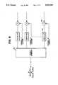
- FIG. 2is a block diagram of the apparatus of the invention using mismatched phase modulation and demodulator which may be used to process the signal;
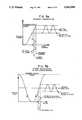
- FIG. 3Ais a graphical representation of optical output power as a function of laser current for linear intensity modulation
- FIG. 3Bis a graphical representation of the optical power output as a function of phase for phase modulation in the linear region
- FIG. 3Cis similar to FIG. 3B showing phase modulation in the non-linear region
- FIG. 3Dis a diagram of phase modulation as a function of intensity
- FIG. 4is a schematic of another modulator and associated circuits which may be used in the method taught by the invention.
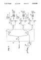
- FIG. 5is a diagram of an embodiment of the invention showing two or more optical signal paths to develop optical signals in quadrature;
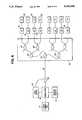
- FIG. 6is a diagram of a yet another embodiment of the invention showing a multiple output system
- FIG. 7is a diagram showing details of a bidirectional communications shown.
- FIG. 8is a detailed diagram showing a multiplexer with power combiner used in the communications system shown in FIG. 7.
- known fiber optic analog signal transmission systemsuse the information signal to vary the intensity or amplitude of a source of light, e.g., a diode pumped laser, and are limited in the dynamic range of the signal which can be transmitted by the noise intensity associated with the source.
- the method of this inventionavoids this limitation by using the analog information and the optical characteristics of light to produce phase modulated signals which may be transmitted by fiber optics or recombined and then transmitted by optical fibers.
- a source of analog information 10such as an antenna receiving microwave or rf signals, may be connected directly to a laser 12 which, e.g., may be a distributed feed back laser operating at 1.3 microns.
- a microwave carrier signal of large amplitude so as to generate a large second harmonic at the output of the phase modulatoris also applied to the laser.
- the output of the laseris an optical signal that is frequency modulated with the analog information.
- This optical signal containing the information of interestmay be applied to a modulator 14 to produce an optical signal that is phase modulated with the information of interest.
- a modulator 14 of the kind that may be used in the methodis a mismatched pathlength interferometer as shown in FIG. 2 of the drawings. It may consist of two fiber-optic couplers 32 and 34 constructed to operate at the frequency of the laser. Fiber-optic coupler 32 divides the optical signal beam into two components, and fiber-optic coupler 34 coherently recombines the two components to produce a phase-modulated optical signal.
- the modulation phase shift ⁇is given by:
- the AC output of the interferometer 14is a composite signal defined as:
- a and Bare the amplitudes of the two component optical beams whose polarizations are identical, J 0 , and J 1 are Bessel functions, X A is the amplitude of the carrier signal at angular frequency w, Y is the phase signal of interest, and Z is the phase variation due to low frequency thermal effects and any static phase difference.
- Reference to FIGS. 3A through 3Ddemonstrates that phase modulation has a significant advantage over intensity modulation for transmitting analog signal information.
- FIG. 3demonstrates how phase modulation relates to the optical intensity.
- linear intensity modulationis shown in FIG. 3A where the maximum laser output power provides a limit on the extent of modulation. This is also true for phase modulation, although 100% modulation depth can be obtained at lower drive currents, and large dynamic range can be achieved by increasing the drive current beyond that point.
- FIG. 3Billustrates phase modulation in the linear region with an output that is very similar to that obtained from intensity modulation.
- the biasis set at 4 mW, allowing a 3 mApp (-12.5 dBm) analog signal current excursion before the maximum 5 mW output power is reached. Comparing the required analog signal drive powers for conventional intensity modulation and for phase modulation it is clear that the advantage rests with the phase modulation process.
- the optical frequency shiftis 0.15 GHz/mA.
- FIG. 3Cshows that when the phase modulation exceeds the maximum power level, the non-linear nature of this process provides a foldover in frequency. For the static phase shift shown in this Figure a frequency doubling occurs.
- a signal processoras will be discussed below is required to linearize the output. In principle, by driving the laser to the maximum allowable current, approximately 10 dB (total 87 dB) additional dynamic range can be achieved, however, the signal when processed or demodulated to obtain the analog information of interest should incorporate techniques to cancel the direct intensity modulation term. This can be as simple as providing cross coupling between the two separate processing paths.
- a signal processor 18 that may be used to demodulate the signal S(t)is shown in FIGS. 1 and 2 coupled to the modulator 14 on its input side by a fiber optic 16 and coupled on the output to an approximate output device 20, e.g., radar receiver.
- the optical signal path provided by the fibermay exceed 10 km as in intensity modulated fiber optic transmission systems.
- the processor 18includes a photodetector 40 connected to convert the modulated optical signal into an electrical signal which, if necessary, may be amplified by an amplifier 42 and applied either to signal processing circuits or applied directly to the utilization device 20 as determined by the end use application, type of light source used and the circuitry employed by the modulator.
- the output of the amplifier 42is the electrical representation of the signal S(t) and is applied to high/low band pass filter circuits 44 to divide the signal into high and low frequency components.
- the low frequency componentis given by the formula:
- the high frequency componentincludes the carrier signal and is represented by:
- the analog signal Yi.e., the signal of interest, is contained in both high and low pass components.
- the high pass componentis mixed with a signal produced by a local oscillator 46 in a mixer 48 where the oscillator 46 operates at the carrier frequency in the example given, w.
- a phaselocked loopcomprising a low pass filter 50 and amplifier 52 may be connected from the output of the mixer 48 to stabilize the local oscillator.
- the mixer 48is connected to a second low pass filter 54 to produce a baseband output:
- This signalmay be passed through an amplifier 56, and is in quadrature with the signal S 1 (t) which may be passed through an amplifier 58 connected to the low pass side of the filter 44. It should be noted that the use of a baseband channel minimizes the required frequency response of the signal processor providing maximum dynamic range and bandwidth performance.
- the outputs of the amplifiers 56, 58are connected in quadrature to a conventional differentiate cross multiply circuitry.
- the amplifier 56provides input to a differentiator 60 which on its output is connected to a mixer 62 which is also connected to receive the low pass component from the amplifier 58.
- the high pass componentis applied to a mixer 64 and there mixed with the output of a differentiator 66 receiving as its input a signal from the low pass amplifier 58.
- the signals from the mixersmay be applied as input signals to a differential amplifier 68 operating into an integrator 70 to produce a composite signal (Y+Z).
- the analog signal of interest (Y)is frequency separated from extraneous low frequency effects (Z).
- the signal Yis, therefore, made available at the remote location to drive a utilization device 20 which, as previously stated, may be a radar or television receiver or other high frequency utilization device.
- phase noise produced either by the source or the mismatched interferometercan be a problem.
- This problemmay be overcome by substituting a matched pathlength modulator for the modulator described above.
- a Mach-Zehender interferometeris shown coupled to receive a light beam on a waveguide 80 with the analog source applied as an input to electrode 81.
- This sourcemay also have a microwave carrier signal or laser amplitude applied to it.
- the light beamis split by a splitter/combiner 82 and applied straight waveguide sections 84 and 86. Either or both of these sections may be modulated with the rf or microwave analog signal to produce a phase shift between the optical beams in each of the sections 84 and 86.
- optical signalscan then either be recombined as by using a combiner/splitter 88 to produce a signal of the kind discussed above which signal can be applied to the fiber optic 16 as previously described. It should be appreciated that instead of recombining the optical signals at the modulator end, each of the phase separated signals could be transmitted by separate fiber optics to the demodulator 18 and there optically recombined.
- a feedback bias controlmight be applied to stabilize the signal.
- the signal from the combiner/splitter 88may be applied to an optical fiber coupler or chip 89 to obtain a small portion of the optical signal which may be used in a closed servo loop.
- the split off portion of the optical signalmay be detected and converted to an electrical signal used as a pick-off signal for electronic bias control 85 fed back to Mach-Zehender interferometer.
- the advantage of this apparatusis that phase noise from the light source is eliminated thus permitting the use of low coherence sources in the method.
- Most of the light from the outputshould be propagated through fiber optics to the demodulator or signal processor 18 described above. Additional stabilization may be obtained by maintaining the operating temperature of the interferometer.
- a thermal electric cooler 87could be attached to the modulator substrate to provide a stable operating temperature.
- FIG. 5 of the drawingsA quasi-static configuration is shown in FIG. 5 of the drawings.
- the laser 12is frequency modulated by the source of rf or microwave signals 10, and light from the laser is launched into an optical fiber coupler 90 having two outputs, 91 and 92.
- a fiber phase modulatormay be constructed by wrapping the fiber 92 on a piezoelectric cylinder which may be driven by a low frequency source, e.g., a source operating at a few kHz, to provide a pilot tone for an AC servo loop.
- a low frequency sourcee.g., a source operating at a few kHz
- the light in the fibers 91 and 92is further divided using couplers 94 and 95 into fibers 96 and 97 on the output side of coupler 94 and fibers 98 and 99 on the output side of the coupler 95.
- These four beamsmay be coherently combined to form separate interferometers.
- fibers 96 and 98may be coupled to combine light signals in a coupler 100, to form one interferometer, and fibers 97 and 99 may be coupled to combine light in a coupler 102 to form another interferometer.
- the pilot tone generator formed by wrapping the fiber optic 92is located to place a pilot tone on each of the fibers 98 and 99, and these tone signals may be inputted to photodetectors 104 and 106 respectively.
- the respective signals generated by the pilot tonescan then be amplified with amplifiers 108 and 110 respectively and combined in a mixer 112 operating as a phase detector to determine the relative phase between the two pilot tone signals.
- the output of the mixer 112may be integrated in an integrator 114 to generate a dc voltage for a fiber modulator 116.
- the output of the integrator 114modulates the fiber modulator 116 in a manner which locks the two interferometers in quadrature.
- the fiber optics 96 and 97are also in quadrature due to the optical phase locked loop. These signals may then be transmitted to the differentiate cross multiply circuits in the demodulator 18 as previously described.
- the systems as describedcan be further refined and improved in both their optical transmission capabilities and in the dynamic range of information that can be transmitted to remote locations by using a high power low noise lasers as the source of light.
- a high power low noise lasersas the source of light.
- a diode pumped YAG lasersuch as those made by Amoco Laser, has inherently low noise with relative intensity noise (-150 dB relative to the outpower of the laser). These sources enhance the system such that it may be used in signal distribution and telecommunication systems.
- FIG. 6 of the drawingsa system for distributing an analog signal, e.g., television signals received on an antenna, to a plurality of utilization devices 20, e.g., television receivers, is shown.
- a high power source of lightis used, e.g., an Amoco Laser YAG, together with a Mach-Zehender interferometer to produce a phase or intensity modulated signal in the fiber optic 16.
- This signalmay be coupled to a fiber distribution assembly 125 comprised of passive couplers 127 connected in a tree to, split the information on the primary transmission fiber 16 into eight output signals each of which is connected to, demodulator or signal processor 18 used as previously described to drive a receiver 20.
- This systemhas high band width capacity and large distribution capability. It permits, therefore, high channel capacity in television system with low harmonic distortion.
- the systemcan be made bidirectional by adding appropriate circuitry in the signal processor and in the return direction towards the analog source 10.
- a source of analog signalssuch as a television camera 130 may be connected as an input to a source of light 132, such as a light emitting diode, to produce an optical signal 134 modulated with the information from the camera.
- Cameras and LEDsmay be associated with each signal processor 18 such that in the system described, at least eight parties may be tied in from the utilization end of the system.
- the systemcan, however, be expanded to allow up to 27 conversations simultaneously with up to 126 viewers.
- a modulated signal 134 from an LED 132may be coupled back to the passive distribution system 125 by using previously unused ports in the couplers 127. These ports can be used to transmit the modulated optical signals using fiber optics to receiving elements at the remote location, i.e., at the location of the source 10, which elements comprise photo detectors 136 and appropriate amplifiers 138 for converting the optical signals to electrical signals containing the information originally produced by the cameras.
- Each amplifier 138may be connected as an input to a multiplexer which as shown in FIG. 8 of the drawings comprises a plurality of mixers 140 each coupled to also receive an appropriate television channel carrier signal.
- the carrier signal in each inputis modulated with the information from the amplifier, and the modulated carrier may then be filtered in a single side band filter 142 to produce the appropriate bandwidth. All of the carrier channels may then be combined in a power combiner 144 applied on its output to the analog source 10 or to the modulator 12 depending on the kind employed in the system.
- wavelength multiplierswhere the optical splitting ratio is wavelength dependent, will improve the optical efficiency of the system over 3 dB splitters.
- Fiber devices for the systemare commercially available, and in the system described, the wavelength form the LEDs may, e.g., 1.275 microns with the diode pumped solid state laser (YAG) operating at 1.319 microns.
- YAGdiode pumped solid state laser
Landscapes
- Physics & Mathematics (AREA)
- Engineering & Computer Science (AREA)
- Computer Networks & Wireless Communication (AREA)
- Electromagnetism (AREA)
- Signal Processing (AREA)
- Nonlinear Science (AREA)
- General Physics & Mathematics (AREA)
- Radar, Positioning & Navigation (AREA)
- Remote Sensing (AREA)
- Optics & Photonics (AREA)
- Optical Communication System (AREA)
Abstract
Description
φ=2πDν/c (1)
S(t)=2AB[J.sub.0 (X.sub.A)cos(Y+Z)-J.sub.1 (X.sub.A) sin(wt) sin (Y+Z)+. . . ] (2)
S.sub.1 (t)=2ABJ.sub.0 (X.sub.A)cos(Y+Z) (3)
S.sub.2 (t)=2ABJ.sub.1 (X.sub.A) sin(Y+Z) sin(wt) (4)
S.sub.2 =-ABJ.sub.1 (X.sub.A)sin (Y+Z) (5)
Claims (25)
Priority Applications (1)
| Application Number | Priority Date | Filing Date | Title |
|---|---|---|---|
| US07/271,890US5042086A (en) | 1988-11-16 | 1988-11-16 | Method and means for transmitting large dynamic analog signals in optical fiber systems |
Applications Claiming Priority (1)
| Application Number | Priority Date | Filing Date | Title |
|---|---|---|---|
| US07/271,890US5042086A (en) | 1988-11-16 | 1988-11-16 | Method and means for transmitting large dynamic analog signals in optical fiber systems |
Publications (1)
| Publication Number | Publication Date |
|---|---|
| US5042086Atrue US5042086A (en) | 1991-08-20 |
Family
ID=23037524
Family Applications (1)
| Application Number | Title | Priority Date | Filing Date |
|---|---|---|---|
| US07/271,890Expired - LifetimeUS5042086A (en) | 1988-11-16 | 1988-11-16 | Method and means for transmitting large dynamic analog signals in optical fiber systems |
Country Status (1)
| Country | Link |
|---|---|
| US (1) | US5042086A (en) |
Cited By (66)
| Publication number | Priority date | Publication date | Assignee | Title |
|---|---|---|---|---|
| WO1994000928A1 (en)* | 1992-06-29 | 1994-01-06 | British Telecommunications Public Limited Company | Optical source for communications system |
| US5289550A (en)* | 1990-03-14 | 1994-02-22 | Plastow Robert J | Modulated light source with a linear transfer function and method utilizing same |
| US5296860A (en)* | 1991-11-04 | 1994-03-22 | Li Ming Chiang | Optical fiber based bistatic radar |
| US5297273A (en)* | 1990-08-30 | 1994-03-22 | Westinghouse Electric Corp. | System for optically splitting high-speed digital signals using cascading tree-type configuration wherein the number of successive level of cascading increase by a factor of two |
| WO1994014209A3 (en)* | 1992-12-03 | 1994-08-04 | Amoco Corp | Optical self-heterodyne remote antenna system |
| US5717708A (en)* | 1995-11-09 | 1998-02-10 | Mells; Bradley | Method and apparatus of stabilizing a semiconductor laser |
| US5930024A (en)* | 1996-10-23 | 1999-07-27 | Scientific-Atlanta, Inc. | Suppression of stimulated Brillouin scattering in optical transmission system |
| US6118397A (en)* | 1998-06-17 | 2000-09-12 | Trw Inc. | Fully optical analog to digital converters with complementary outputs |
| WO2001056196A1 (en)* | 2000-01-26 | 2001-08-02 | Lockheed Martin Corporation | Use of phase shift keyed coherent optical signaling in a wavelength division multiplexed optical fiber links |
| US20040136454A1 (en)* | 2002-12-24 | 2004-07-15 | General Electric Company | System and method for digital transmission and modulation of conjugate pulse position |
| US7074301B2 (en) | 2002-06-11 | 2006-07-11 | Rayonier Products And Financial Services Company | Chemically cross-linked cellulose fiber and method of making same |
| US7127172B1 (en) | 1999-06-02 | 2006-10-24 | Massachusetts Institute Of Technology | Optical frequency filter |
| US20070269170A1 (en)* | 2006-05-19 | 2007-11-22 | Easton Martyn N | Fiber optic cable and fiber optic cable assembly for wireless access |
| US20070292137A1 (en)* | 2006-06-16 | 2007-12-20 | Michael Sauer | Redundant transponder array for a radio-over-fiber optical fiber cable |
| US20080232305A1 (en)* | 2006-12-19 | 2008-09-25 | Yair Oren | Distributed Antenna System for MIMO Technologies |
| US20090097855A1 (en)* | 2007-10-12 | 2009-04-16 | Dean Michael Thelen | Hybrid wireless/wired RoF transponder and hybrid RoF communication system using same |
| US7627250B2 (en) | 2006-08-16 | 2009-12-01 | Corning Cable Systems Llc | Radio-over-fiber transponder with a dual-band patch antenna system |
| US20100054746A1 (en)* | 2007-07-24 | 2010-03-04 | Eric Raymond Logan | Multi-port accumulator for radio-over-fiber (RoF) wireless picocellular systems |
| US7787823B2 (en) | 2006-09-15 | 2010-08-31 | Corning Cable Systems Llc | Radio-over-fiber (RoF) optical fiber cable system with transponder diversity and RoF wireless picocellular system using same |
| US7848654B2 (en) | 2006-09-28 | 2010-12-07 | Corning Cable Systems Llc | Radio-over-fiber (RoF) wireless picocellular system with combined picocells |
| US20110200325A1 (en)* | 2010-02-15 | 2011-08-18 | Andrey Kobyakov | Dynamic Cell Bonding (DCB) for Radio-over-Fiber (RoF)-Based Networks and Communication Systems and Related Methods |
| US20120028594A1 (en)* | 2010-07-28 | 2012-02-02 | Motorola, Inc. | Method and apparatus for imbalance-free fm demodulation in direct conversion radio receivers |
| US8111998B2 (en) | 2007-02-06 | 2012-02-07 | Corning Cable Systems Llc | Transponder systems and methods for radio-over-fiber (RoF) wireless picocellular systems |
| US8548330B2 (en) | 2009-07-31 | 2013-10-01 | Corning Cable Systems Llc | Sectorization in distributed antenna systems, and related components and methods |
| US8644844B2 (en) | 2007-12-20 | 2014-02-04 | Corning Mobileaccess Ltd. | Extending outdoor location based services and applications into enclosed areas |
| US9037143B2 (en) | 2010-08-16 | 2015-05-19 | Corning Optical Communications LLC | Remote antenna clusters and related systems, components, and methods supporting digital data signal propagation between remote antenna units |
| US9042732B2 (en) | 2010-05-02 | 2015-05-26 | Corning Optical Communications LLC | Providing digital data services in optical fiber-based distributed radio frequency (RF) communication systems, and related components and methods |
| US9112611B2 (en) | 2009-02-03 | 2015-08-18 | Corning Optical Communications LLC | Optical fiber-based distributed antenna systems, components, and related methods for calibration thereof |
| US9178635B2 (en) | 2014-01-03 | 2015-11-03 | Corning Optical Communications Wireless Ltd | Separation of communication signal sub-bands in distributed antenna systems (DASs) to reduce interference |
| US9184843B2 (en) | 2011-04-29 | 2015-11-10 | Corning Optical Communications LLC | Determining propagation delay of communications in distributed antenna systems, and related components, systems, and methods |
| US9219879B2 (en) | 2009-11-13 | 2015-12-22 | Corning Optical Communications LLC | Radio-over-fiber (ROF) system for protocol-independent wired and/or wireless communication |
| US9240835B2 (en) | 2011-04-29 | 2016-01-19 | Corning Optical Communications LLC | Systems, methods, and devices for increasing radio frequency (RF) power in distributed antenna systems |
| US9247543B2 (en) | 2013-07-23 | 2016-01-26 | Corning Optical Communications Wireless Ltd | Monitoring non-supported wireless spectrum within coverage areas of distributed antenna systems (DASs) |
| US9258052B2 (en) | 2012-03-30 | 2016-02-09 | Corning Optical Communications LLC | Reducing location-dependent interference in distributed antenna systems operating in multiple-input, multiple-output (MIMO) configuration, and related components, systems, and methods |
| US9325429B2 (en) | 2011-02-21 | 2016-04-26 | Corning Optical Communications LLC | Providing digital data services as electrical signals and radio-frequency (RF) communications over optical fiber in distributed communications systems, and related components and methods |
| US9357551B2 (en) | 2014-05-30 | 2016-05-31 | Corning Optical Communications Wireless Ltd | Systems and methods for simultaneous sampling of serial digital data streams from multiple analog-to-digital converters (ADCS), including in distributed antenna systems |
| US9385810B2 (en) | 2013-09-30 | 2016-07-05 | Corning Optical Communications Wireless Ltd | Connection mapping in distributed communication systems |
| US9420542B2 (en) | 2014-09-25 | 2016-08-16 | Corning Optical Communications Wireless Ltd | System-wide uplink band gain control in a distributed antenna system (DAS), based on per band gain control of remote uplink paths in remote units |
| US9455784B2 (en) | 2012-10-31 | 2016-09-27 | Corning Optical Communications Wireless Ltd | Deployable wireless infrastructures and methods of deploying wireless infrastructures |
| US9525488B2 (en) | 2010-05-02 | 2016-12-20 | Corning Optical Communications LLC | Digital data services and/or power distribution in optical fiber-based distributed communications systems providing digital data and radio frequency (RF) communications services, and related components and methods |
| US9525472B2 (en) | 2014-07-30 | 2016-12-20 | Corning Incorporated | Reducing location-dependent destructive interference in distributed antenna systems (DASS) operating in multiple-input, multiple-output (MIMO) configuration, and related components, systems, and methods |
| US9531452B2 (en) | 2012-11-29 | 2016-12-27 | Corning Optical Communications LLC | Hybrid intra-cell / inter-cell remote unit antenna bonding in multiple-input, multiple-output (MIMO) distributed antenna systems (DASs) |
| US9602210B2 (en) | 2014-09-24 | 2017-03-21 | Corning Optical Communications Wireless Ltd | Flexible head-end chassis supporting automatic identification and interconnection of radio interface modules and optical interface modules in an optical fiber-based distributed antenna system (DAS) |
| US9621293B2 (en) | 2012-08-07 | 2017-04-11 | Corning Optical Communications Wireless Ltd | Distribution of time-division multiplexed (TDM) management services in a distributed antenna system, and related components, systems, and methods |
| US9647758B2 (en) | 2012-11-30 | 2017-05-09 | Corning Optical Communications Wireless Ltd | Cabling connectivity monitoring and verification |
| US9661781B2 (en) | 2013-07-31 | 2017-05-23 | Corning Optical Communications Wireless Ltd | Remote units for distributed communication systems and related installation methods and apparatuses |
| US9673904B2 (en) | 2009-02-03 | 2017-06-06 | Corning Optical Communications LLC | Optical fiber-based distributed antenna systems, components, and related methods for calibration thereof |
| US9681313B2 (en) | 2015-04-15 | 2017-06-13 | Corning Optical Communications Wireless Ltd | Optimizing remote antenna unit performance using an alternative data channel |
| US9715157B2 (en) | 2013-06-12 | 2017-07-25 | Corning Optical Communications Wireless Ltd | Voltage controlled optical directional coupler |
| US9729267B2 (en) | 2014-12-11 | 2017-08-08 | Corning Optical Communications Wireless Ltd | Multiplexing two separate optical links with the same wavelength using asymmetric combining and splitting |
| US9730228B2 (en) | 2014-08-29 | 2017-08-08 | Corning Optical Communications Wireless Ltd | Individualized gain control of remote uplink band paths in a remote unit in a distributed antenna system (DAS), based on combined uplink power level in the remote unit |
| US9775123B2 (en) | 2014-03-28 | 2017-09-26 | Corning Optical Communications Wireless Ltd. | Individualized gain control of uplink paths in remote units in a distributed antenna system (DAS) based on individual remote unit contribution to combined uplink power |
| US9807700B2 (en) | 2015-02-19 | 2017-10-31 | Corning Optical Communications Wireless Ltd | Offsetting unwanted downlink interference signals in an uplink path in a distributed antenna system (DAS) |
| US9948349B2 (en) | 2015-07-17 | 2018-04-17 | Corning Optical Communications Wireless Ltd | IOT automation and data collection system |
| US9974074B2 (en) | 2013-06-12 | 2018-05-15 | Corning Optical Communications Wireless Ltd | Time-division duplexing (TDD) in distributed communications systems, including distributed antenna systems (DASs) |
| US10096909B2 (en) | 2014-11-03 | 2018-10-09 | Corning Optical Communications Wireless Ltd. | Multi-band monopole planar antennas configured to facilitate improved radio frequency (RF) isolation in multiple-input multiple-output (MIMO) antenna arrangement |
| US10110308B2 (en) | 2014-12-18 | 2018-10-23 | Corning Optical Communications Wireless Ltd | Digital interface modules (DIMs) for flexibly distributing digital and/or analog communications signals in wide-area analog distributed antenna systems (DASs) |
| US10128951B2 (en) | 2009-02-03 | 2018-11-13 | Corning Optical Communications LLC | Optical fiber-based distributed antenna systems, components, and related methods for monitoring and configuring thereof |
| US10135533B2 (en) | 2014-11-13 | 2018-11-20 | Corning Optical Communications Wireless Ltd | Analog distributed antenna systems (DASS) supporting distribution of digital communications signals interfaced from a digital signal source and analog radio frequency (RF) communications signals |
| US10136200B2 (en) | 2012-04-25 | 2018-11-20 | Corning Optical Communications LLC | Distributed antenna system architectures |
| US10187151B2 (en) | 2014-12-18 | 2019-01-22 | Corning Optical Communications Wireless Ltd | Digital-analog interface modules (DAIMs) for flexibly distributing digital and/or analog communications signals in wide-area analog distributed antenna systems (DASs) |
| US10236924B2 (en) | 2016-03-31 | 2019-03-19 | Corning Optical Communications Wireless Ltd | Reducing out-of-channel noise in a wireless distribution system (WDS) |
| US20190123823A1 (en)* | 2017-10-20 | 2019-04-25 | Arris Enterprises Llc | Stimulated brillouin scattering (sbs) suppression in an optical communications system |
| US10560214B2 (en) | 2015-09-28 | 2020-02-11 | Corning Optical Communications LLC | Downlink and uplink communication path switching in a time-division duplex (TDD) distributed antenna system (DAS) |
| US10659163B2 (en) | 2014-09-25 | 2020-05-19 | Corning Optical Communications LLC | Supporting analog remote antenna units (RAUs) in digital distributed antenna systems (DASs) using analog RAU digital adaptors |
| US11178609B2 (en) | 2010-10-13 | 2021-11-16 | Corning Optical Communications LLC | Power management for remote antenna units in distributed antenna systems |
Citations (20)
| Publication number | Priority date | Publication date | Assignee | Title |
|---|---|---|---|---|
| US3517334A (en)* | 1964-07-02 | 1970-06-23 | Trw Inc | Laser pumped by multiple photon absorption |
| US3732505A (en)* | 1972-06-07 | 1973-05-08 | Us Air Force | End pump device for a laser |
| US3956626A (en)* | 1973-06-14 | 1976-05-11 | Mcdonnell Douglas Corporation | Pulse quaternary communication means |
| US4236243A (en)* | 1978-04-20 | 1980-11-25 | National Research Development Corporation | Telecommunication systems |
| US4436425A (en)* | 1982-03-29 | 1984-03-13 | The United States Of America As Represented By The Secretary Of The Navy | Signal waveform detector using synthetic FM demodulation |
| US4533247A (en)* | 1981-09-03 | 1985-08-06 | International Standard Electric Corporation | Optical transmission system |
| US4578793A (en)* | 1984-07-13 | 1986-03-25 | The Board Of Trustees Of The Leland Stanford Junior University | Solid-state non-planar internally reflecting ring laser |
| US4653056A (en)* | 1985-05-01 | 1987-03-24 | Spectra-Physics, Inc. | Nd-YAG laser |
| US4656635A (en)* | 1985-05-01 | 1987-04-07 | Spectra-Physics, Inc. | Laser diode pumped solid state laser |
| US4694276A (en)* | 1986-08-13 | 1987-09-15 | Analog Devices, Inc. | Interferometric analog-to-digital converter and method for operation |
| US4701929A (en)* | 1985-12-19 | 1987-10-20 | Spectra-Physics, Inc. | Laser diode pumped solid state laser |
| US4701928A (en)* | 1985-10-02 | 1987-10-20 | Board Of Trustees, Leland J. Stanford University | Diode laser pumped co-doped laser |
| US4730335A (en)* | 1986-06-26 | 1988-03-08 | Amoco Corporation | Solid state laser and method of making |
| US4731795A (en)* | 1986-06-26 | 1988-03-15 | Amoco Corporation | Solid state laser |
| US4734912A (en)* | 1986-06-06 | 1988-03-29 | Lightwave Electronics Corp. | Laser diode end pumped Nd:YAG single mode laser |
| US4749277A (en)* | 1987-01-20 | 1988-06-07 | Gte Laboratories Incorporated | Methods of and apparatus for measuring the frequency response of optical detectors |
| US4752132A (en)* | 1986-10-24 | 1988-06-21 | Litton Systems, Inc. | Low power control interferometric sensor with wide dynamic range |
| US4768186A (en)* | 1986-02-11 | 1988-08-30 | Pirelli Cable Corporation | Multiplex transmission of analog signals by fiber optic channel |
| US4770535A (en)* | 1985-02-08 | 1988-09-13 | The Board Of Trustees Of The Leland Stanford Junior University | Distributed sensor array and method using a pulsed signal source |
| US4805235A (en)* | 1986-02-17 | 1989-02-14 | Nec Corporation | Optical transmitter comprising an optical frequency discriminator |
- 1988
- 1988-11-16USUS07/271,890patent/US5042086A/ennot_activeExpired - Lifetime
Patent Citations (22)
| Publication number | Priority date | Publication date | Assignee | Title |
|---|---|---|---|---|
| US3517334A (en)* | 1964-07-02 | 1970-06-23 | Trw Inc | Laser pumped by multiple photon absorption |
| US3732505A (en)* | 1972-06-07 | 1973-05-08 | Us Air Force | End pump device for a laser |
| US3956626A (en)* | 1973-06-14 | 1976-05-11 | Mcdonnell Douglas Corporation | Pulse quaternary communication means |
| US4236243A (en)* | 1978-04-20 | 1980-11-25 | National Research Development Corporation | Telecommunication systems |
| US4533247A (en)* | 1981-09-03 | 1985-08-06 | International Standard Electric Corporation | Optical transmission system |
| US4436425A (en)* | 1982-03-29 | 1984-03-13 | The United States Of America As Represented By The Secretary Of The Navy | Signal waveform detector using synthetic FM demodulation |
| US4578793A (en)* | 1984-07-13 | 1986-03-25 | The Board Of Trustees Of The Leland Stanford Junior University | Solid-state non-planar internally reflecting ring laser |
| US4770535A (en)* | 1985-02-08 | 1988-09-13 | The Board Of Trustees Of The Leland Stanford Junior University | Distributed sensor array and method using a pulsed signal source |
| US4653056A (en)* | 1985-05-01 | 1987-03-24 | Spectra-Physics, Inc. | Nd-YAG laser |
| US4656635A (en)* | 1985-05-01 | 1987-04-07 | Spectra-Physics, Inc. | Laser diode pumped solid state laser |
| US4653056B1 (en)* | 1985-05-01 | 1990-07-24 | Spectra Physics | |
| US4701928A (en)* | 1985-10-02 | 1987-10-20 | Board Of Trustees, Leland J. Stanford University | Diode laser pumped co-doped laser |
| US4701929A (en)* | 1985-12-19 | 1987-10-20 | Spectra-Physics, Inc. | Laser diode pumped solid state laser |
| US4701929B1 (en)* | 1985-12-19 | 1990-07-10 | Spectra Physics | |
| US4768186A (en)* | 1986-02-11 | 1988-08-30 | Pirelli Cable Corporation | Multiplex transmission of analog signals by fiber optic channel |
| US4805235A (en)* | 1986-02-17 | 1989-02-14 | Nec Corporation | Optical transmitter comprising an optical frequency discriminator |
| US4734912A (en)* | 1986-06-06 | 1988-03-29 | Lightwave Electronics Corp. | Laser diode end pumped Nd:YAG single mode laser |
| US4731795A (en)* | 1986-06-26 | 1988-03-15 | Amoco Corporation | Solid state laser |
| US4730335A (en)* | 1986-06-26 | 1988-03-08 | Amoco Corporation | Solid state laser and method of making |
| US4694276A (en)* | 1986-08-13 | 1987-09-15 | Analog Devices, Inc. | Interferometric analog-to-digital converter and method for operation |
| US4752132A (en)* | 1986-10-24 | 1988-06-21 | Litton Systems, Inc. | Low power control interferometric sensor with wide dynamic range |
| US4749277A (en)* | 1987-01-20 | 1988-06-07 | Gte Laboratories Incorporated | Methods of and apparatus for measuring the frequency response of optical detectors |
Non-Patent Citations (14)
| Title |
|---|
| A Dandridge, A. B. Tveten and T. G. Giallorenzi, "Homodyne Interferometric Demodulation," IEEE Journal of Quantum Electronics QE-18, pp. 1647-1697, (10-1982). |
| A Dandridge, A. B. Tveten and T. G. Giallorenzi, Homodyne Interferometric Demodulation, IEEE Journal of Quantum Electronics QE 18, pp. 1647 1697, (10 1982).* |
| A. Dandridge and L. Goldberg, "Current Induced Frequency Modulation in Diode Lasers," Electronic Lett. 18, pp. 302-303, (2-1982). |
| A. Dandridge and L. Goldberg, Current Induced Frequency Modulation in Diode Lasers, Electronic Lett. 18, pp. 302 303, (2 1982).* |
| A. Dandridge, "Zero Path-Length Difference in Fiber Optic Interferometers," Journal of Lightwave Technology LT-1, pp. 514-516, (9-1983). |
| A. Dandridge, Zero Path Length Difference in Fiber Optic Interferometers, Journal of Lightwave Technology LT 1, pp. 514 516, (9 1983).* |
| D. G. Fink, Ed. Electronic Engineer s Handbook, Angle Demodulators, by N. R. Powell, pp. 14 22 to 14 28, McGraw Hill Book Company, New York, 11 1988.* |
| D. G. Fink, Ed. Electronic Engineer's Handbook, "Angle Demodulators," by N. R. Powell, pp. 14-22 to 14-28, McGraw-Hill Book Company, New York, 11-1988. |
| J. H. Cole, B. A. Danver and J. A. Bucaro, "Synthetic Heterodyne Interferometric Demodulation," IEEE Journal of Quantum Electronics QE-18, pp. 604-697, (4-1982). |
| J. H. Cole, B. A. Danver and J. A. Bucaro, Synthetic Heterodyne Interferometric Demodulation, IEEE Journal of Quantum Electronics QE 18, pp. 604 697, (4 1982).* |
| K. P. Koo, A. B. Tveten and A. Dandridge, "Passive Stabilization Scheme for Fiber Interferometers Using (3×3) Fiber Directional Couplers," Applied Physics Lett. 41, pp. 616-618, (10-1982). |
| K. P. Koo, A. B. Tveten and A. Dandridge, Passive Stabilization Scheme for Fiber Interferometers Using (3 3) Fiber Directional Couplers, Applied Physics Lett. 41, pp. 616 618, (10 1982).* |
| R. A. Becker, "Traveling Wave Electro-Optic Modulator with Maximum Bandwidth-Length Product," Appl. Phys. Lett. 45, pp. 1168-1170, (12-1984). |
| R. A. Becker, Traveling Wave Electro Optic Modulator with Maximum Bandwidth Length Product, Appl. Phys. Lett. 45, pp. 1168 1170, (12 1984).* |
Cited By (120)
| Publication number | Priority date | Publication date | Assignee | Title |
|---|---|---|---|---|
| US5289550A (en)* | 1990-03-14 | 1994-02-22 | Plastow Robert J | Modulated light source with a linear transfer function and method utilizing same |
| US5297273A (en)* | 1990-08-30 | 1994-03-22 | Westinghouse Electric Corp. | System for optically splitting high-speed digital signals using cascading tree-type configuration wherein the number of successive level of cascading increase by a factor of two |
| USRE36944E (en)* | 1991-11-04 | 2000-11-07 | Li; Ming-Chiang | Optical fiber based bistatic radar |
| US5296860A (en)* | 1991-11-04 | 1994-03-22 | Li Ming Chiang | Optical fiber based bistatic radar |
| WO1994000928A1 (en)* | 1992-06-29 | 1994-01-06 | British Telecommunications Public Limited Company | Optical source for communications system |
| WO1994014209A3 (en)* | 1992-12-03 | 1994-08-04 | Amoco Corp | Optical self-heterodyne remote antenna system |
| US5717708A (en)* | 1995-11-09 | 1998-02-10 | Mells; Bradley | Method and apparatus of stabilizing a semiconductor laser |
| US5930024A (en)* | 1996-10-23 | 1999-07-27 | Scientific-Atlanta, Inc. | Suppression of stimulated Brillouin scattering in optical transmission system |
| US6118397A (en)* | 1998-06-17 | 2000-09-12 | Trw Inc. | Fully optical analog to digital converters with complementary outputs |
| US7127172B1 (en) | 1999-06-02 | 2006-10-24 | Massachusetts Institute Of Technology | Optical frequency filter |
| WO2001056196A1 (en)* | 2000-01-26 | 2001-08-02 | Lockheed Martin Corporation | Use of phase shift keyed coherent optical signaling in a wavelength division multiplexed optical fiber links |
| US7074301B2 (en) | 2002-06-11 | 2006-07-11 | Rayonier Products And Financial Services Company | Chemically cross-linked cellulose fiber and method of making same |
| US20040136454A1 (en)* | 2002-12-24 | 2004-07-15 | General Electric Company | System and method for digital transmission and modulation of conjugate pulse position |
| US7539245B2 (en) | 2002-12-24 | 2009-05-26 | General Electric Company | System and method for digital transmission and modulation of conjugate pulse position |
| US20070269170A1 (en)* | 2006-05-19 | 2007-11-22 | Easton Martyn N | Fiber optic cable and fiber optic cable assembly for wireless access |
| US8472767B2 (en) | 2006-05-19 | 2013-06-25 | Corning Cable Systems Llc | Fiber optic cable and fiber optic cable assembly for wireless access |
| US7590354B2 (en) | 2006-06-16 | 2009-09-15 | Corning Cable Systems Llc | Redundant transponder array for a radio-over-fiber optical fiber cable |
| US20070292137A1 (en)* | 2006-06-16 | 2007-12-20 | Michael Sauer | Redundant transponder array for a radio-over-fiber optical fiber cable |
| US7627250B2 (en) | 2006-08-16 | 2009-12-01 | Corning Cable Systems Llc | Radio-over-fiber transponder with a dual-band patch antenna system |
| US7787823B2 (en) | 2006-09-15 | 2010-08-31 | Corning Cable Systems Llc | Radio-over-fiber (RoF) optical fiber cable system with transponder diversity and RoF wireless picocellular system using same |
| US7848654B2 (en) | 2006-09-28 | 2010-12-07 | Corning Cable Systems Llc | Radio-over-fiber (RoF) wireless picocellular system with combined picocells |
| US9130613B2 (en) | 2006-12-19 | 2015-09-08 | Corning Optical Communications Wireless Ltd | Distributed antenna system for MIMO technologies |
| US8873585B2 (en) | 2006-12-19 | 2014-10-28 | Corning Optical Communications Wireless Ltd | Distributed antenna system for MIMO technologies |
| US20080232305A1 (en)* | 2006-12-19 | 2008-09-25 | Yair Oren | Distributed Antenna System for MIMO Technologies |
| US8111998B2 (en) | 2007-02-06 | 2012-02-07 | Corning Cable Systems Llc | Transponder systems and methods for radio-over-fiber (RoF) wireless picocellular systems |
| US20100054746A1 (en)* | 2007-07-24 | 2010-03-04 | Eric Raymond Logan | Multi-port accumulator for radio-over-fiber (RoF) wireless picocellular systems |
| US8867919B2 (en) | 2007-07-24 | 2014-10-21 | Corning Cable Systems Llc | Multi-port accumulator for radio-over-fiber (RoF) wireless picocellular systems |
| US8718478B2 (en) | 2007-10-12 | 2014-05-06 | Corning Cable Systems Llc | Hybrid wireless/wired RoF transponder and hybrid RoF communication system using same |
| US20090097855A1 (en)* | 2007-10-12 | 2009-04-16 | Dean Michael Thelen | Hybrid wireless/wired RoF transponder and hybrid RoF communication system using same |
| US8175459B2 (en) | 2007-10-12 | 2012-05-08 | Corning Cable Systems Llc | Hybrid wireless/wired RoF transponder and hybrid RoF communication system using same |
| US8644844B2 (en) | 2007-12-20 | 2014-02-04 | Corning Mobileaccess Ltd. | Extending outdoor location based services and applications into enclosed areas |
| US9673904B2 (en) | 2009-02-03 | 2017-06-06 | Corning Optical Communications LLC | Optical fiber-based distributed antenna systems, components, and related methods for calibration thereof |
| US10128951B2 (en) | 2009-02-03 | 2018-11-13 | Corning Optical Communications LLC | Optical fiber-based distributed antenna systems, components, and related methods for monitoring and configuring thereof |
| US9900097B2 (en) | 2009-02-03 | 2018-02-20 | Corning Optical Communications LLC | Optical fiber-based distributed antenna systems, components, and related methods for calibration thereof |
| US10153841B2 (en) | 2009-02-03 | 2018-12-11 | Corning Optical Communications LLC | Optical fiber-based distributed antenna systems, components, and related methods for calibration thereof |
| US9112611B2 (en) | 2009-02-03 | 2015-08-18 | Corning Optical Communications LLC | Optical fiber-based distributed antenna systems, components, and related methods for calibration thereof |
| US8548330B2 (en) | 2009-07-31 | 2013-10-01 | Corning Cable Systems Llc | Sectorization in distributed antenna systems, and related components and methods |
| US9729238B2 (en) | 2009-11-13 | 2017-08-08 | Corning Optical Communications LLC | Radio-over-fiber (ROF) system for protocol-independent wired and/or wireless communication |
| US9485022B2 (en) | 2009-11-13 | 2016-11-01 | Corning Optical Communications LLC | Radio-over-fiber (ROF) system for protocol-independent wired and/or wireless communication |
| US9219879B2 (en) | 2009-11-13 | 2015-12-22 | Corning Optical Communications LLC | Radio-over-fiber (ROF) system for protocol-independent wired and/or wireless communication |
| US8831428B2 (en) | 2010-02-15 | 2014-09-09 | Corning Optical Communications LLC | Dynamic cell bonding (DCB) for radio-over-fiber (RoF)-based networks and communication systems and related methods |
| US8275265B2 (en) | 2010-02-15 | 2012-09-25 | Corning Cable Systems Llc | Dynamic cell bonding (DCB) for radio-over-fiber (RoF)-based networks and communication systems and related methods |
| US20110200325A1 (en)* | 2010-02-15 | 2011-08-18 | Andrey Kobyakov | Dynamic Cell Bonding (DCB) for Radio-over-Fiber (RoF)-Based Networks and Communication Systems and Related Methods |
| US9319138B2 (en) | 2010-02-15 | 2016-04-19 | Corning Optical Communications LLC | Dynamic cell bonding (DCB) for radio-over-fiber (RoF)-based networks and communication systems and related methods |
| US9042732B2 (en) | 2010-05-02 | 2015-05-26 | Corning Optical Communications LLC | Providing digital data services in optical fiber-based distributed radio frequency (RF) communication systems, and related components and methods |
| US9853732B2 (en) | 2010-05-02 | 2017-12-26 | Corning Optical Communications LLC | Digital data services and/or power distribution in optical fiber-based distributed communications systems providing digital data and radio frequency (RF) communications services, and related components and methods |
| US9270374B2 (en) | 2010-05-02 | 2016-02-23 | Corning Optical Communications LLC | Providing digital data services in optical fiber-based distributed radio frequency (RF) communications systems, and related components and methods |
| US9525488B2 (en) | 2010-05-02 | 2016-12-20 | Corning Optical Communications LLC | Digital data services and/or power distribution in optical fiber-based distributed communications systems providing digital data and radio frequency (RF) communications services, and related components and methods |
| US8442474B2 (en)* | 2010-07-28 | 2013-05-14 | Motorola Solutions, Inc. | Method and apparatus for imbalance-free FM demodulation in direct conversion radio receivers |
| US20120028594A1 (en)* | 2010-07-28 | 2012-02-02 | Motorola, Inc. | Method and apparatus for imbalance-free fm demodulation in direct conversion radio receivers |
| US9037143B2 (en) | 2010-08-16 | 2015-05-19 | Corning Optical Communications LLC | Remote antenna clusters and related systems, components, and methods supporting digital data signal propagation between remote antenna units |
| US10014944B2 (en) | 2010-08-16 | 2018-07-03 | Corning Optical Communications LLC | Remote antenna clusters and related systems, components, and methods supporting digital data signal propagation between remote antenna units |
| US11224014B2 (en) | 2010-10-13 | 2022-01-11 | Corning Optical Communications LLC | Power management for remote antenna units in distributed antenna systems |
| US11178609B2 (en) | 2010-10-13 | 2021-11-16 | Corning Optical Communications LLC | Power management for remote antenna units in distributed antenna systems |
| US11212745B2 (en) | 2010-10-13 | 2021-12-28 | Corning Optical Communications LLC | Power management for remote antenna units in distributed antenna systems |
| US11671914B2 (en) | 2010-10-13 | 2023-06-06 | Corning Optical Communications LLC | Power management for remote antenna units in distributed antenna systems |
| US8913892B2 (en) | 2010-10-28 | 2014-12-16 | Coring Optical Communications LLC | Sectorization in distributed antenna systems, and related components and methods |
| US10205538B2 (en) | 2011-02-21 | 2019-02-12 | Corning Optical Communications LLC | Providing digital data services as electrical signals and radio-frequency (RF) communications over optical fiber in distributed communications systems, and related components and methods |
| US9813164B2 (en) | 2011-02-21 | 2017-11-07 | Corning Optical Communications LLC | Providing digital data services as electrical signals and radio-frequency (RF) communications over optical fiber in distributed communications systems, and related components and methods |
| US9325429B2 (en) | 2011-02-21 | 2016-04-26 | Corning Optical Communications LLC | Providing digital data services as electrical signals and radio-frequency (RF) communications over optical fiber in distributed communications systems, and related components and methods |
| US9369222B2 (en) | 2011-04-29 | 2016-06-14 | Corning Optical Communications LLC | Determining propagation delay of communications in distributed antenna systems, and related components, systems, and methods |
| US9240835B2 (en) | 2011-04-29 | 2016-01-19 | Corning Optical Communications LLC | Systems, methods, and devices for increasing radio frequency (RF) power in distributed antenna systems |
| US9184843B2 (en) | 2011-04-29 | 2015-11-10 | Corning Optical Communications LLC | Determining propagation delay of communications in distributed antenna systems, and related components, systems, and methods |
| US10148347B2 (en) | 2011-04-29 | 2018-12-04 | Corning Optical Communications LLC | Systems, methods, and devices for increasing radio frequency (RF) power in distributed antenna systems |
| US9807722B2 (en) | 2011-04-29 | 2017-10-31 | Corning Optical Communications LLC | Determining propagation delay of communications in distributed antenna systems, and related components, systems, and methods |
| US9806797B2 (en) | 2011-04-29 | 2017-10-31 | Corning Optical Communications LLC | Systems, methods, and devices for increasing radio frequency (RF) power in distributed antenna systems |
| US9258052B2 (en) | 2012-03-30 | 2016-02-09 | Corning Optical Communications LLC | Reducing location-dependent interference in distributed antenna systems operating in multiple-input, multiple-output (MIMO) configuration, and related components, systems, and methods |
| US9813127B2 (en) | 2012-03-30 | 2017-11-07 | Corning Optical Communications LLC | Reducing location-dependent interference in distributed antenna systems operating in multiple-input, multiple-output (MIMO) configuration, and related components, systems, and methods |
| US10349156B2 (en) | 2012-04-25 | 2019-07-09 | Corning Optical Communications LLC | Distributed antenna system architectures |
| US10136200B2 (en) | 2012-04-25 | 2018-11-20 | Corning Optical Communications LLC | Distributed antenna system architectures |
| US9621293B2 (en) | 2012-08-07 | 2017-04-11 | Corning Optical Communications Wireless Ltd | Distribution of time-division multiplexed (TDM) management services in a distributed antenna system, and related components, systems, and methods |
| US9973968B2 (en) | 2012-08-07 | 2018-05-15 | Corning Optical Communications Wireless Ltd | Distribution of time-division multiplexed (TDM) management services in a distributed antenna system, and related components, systems, and methods |
| US9455784B2 (en) | 2012-10-31 | 2016-09-27 | Corning Optical Communications Wireless Ltd | Deployable wireless infrastructures and methods of deploying wireless infrastructures |
| US9531452B2 (en) | 2012-11-29 | 2016-12-27 | Corning Optical Communications LLC | Hybrid intra-cell / inter-cell remote unit antenna bonding in multiple-input, multiple-output (MIMO) distributed antenna systems (DASs) |
| US9647758B2 (en) | 2012-11-30 | 2017-05-09 | Corning Optical Communications Wireless Ltd | Cabling connectivity monitoring and verification |
| US10361782B2 (en) | 2012-11-30 | 2019-07-23 | Corning Optical Communications LLC | Cabling connectivity monitoring and verification |
| US9974074B2 (en) | 2013-06-12 | 2018-05-15 | Corning Optical Communications Wireless Ltd | Time-division duplexing (TDD) in distributed communications systems, including distributed antenna systems (DASs) |
| US11792776B2 (en) | 2013-06-12 | 2023-10-17 | Corning Optical Communications LLC | Time-division duplexing (TDD) in distributed communications systems, including distributed antenna systems (DASs) |
| US11291001B2 (en) | 2013-06-12 | 2022-03-29 | Corning Optical Communications LLC | Time-division duplexing (TDD) in distributed communications systems, including distributed antenna systems (DASs) |
| US9715157B2 (en) | 2013-06-12 | 2017-07-25 | Corning Optical Communications Wireless Ltd | Voltage controlled optical directional coupler |
| US10292056B2 (en) | 2013-07-23 | 2019-05-14 | Corning Optical Communications LLC | Monitoring non-supported wireless spectrum within coverage areas of distributed antenna systems (DASs) |
| US9247543B2 (en) | 2013-07-23 | 2016-01-26 | Corning Optical Communications Wireless Ltd | Monitoring non-supported wireless spectrum within coverage areas of distributed antenna systems (DASs) |
| US9526020B2 (en) | 2013-07-23 | 2016-12-20 | Corning Optical Communications Wireless Ltd | Monitoring non-supported wireless spectrum within coverage areas of distributed antenna systems (DASs) |
| US9967754B2 (en) | 2013-07-23 | 2018-05-08 | Corning Optical Communications Wireless Ltd | Monitoring non-supported wireless spectrum within coverage areas of distributed antenna systems (DASs) |
| US9661781B2 (en) | 2013-07-31 | 2017-05-23 | Corning Optical Communications Wireless Ltd | Remote units for distributed communication systems and related installation methods and apparatuses |
| US9385810B2 (en) | 2013-09-30 | 2016-07-05 | Corning Optical Communications Wireless Ltd | Connection mapping in distributed communication systems |
| US9178635B2 (en) | 2014-01-03 | 2015-11-03 | Corning Optical Communications Wireless Ltd | Separation of communication signal sub-bands in distributed antenna systems (DASs) to reduce interference |
| US9775123B2 (en) | 2014-03-28 | 2017-09-26 | Corning Optical Communications Wireless Ltd. | Individualized gain control of uplink paths in remote units in a distributed antenna system (DAS) based on individual remote unit contribution to combined uplink power |
| US9807772B2 (en) | 2014-05-30 | 2017-10-31 | Corning Optical Communications Wireless Ltd. | Systems and methods for simultaneous sampling of serial digital data streams from multiple analog-to-digital converters (ADCs), including in distributed antenna systems |
| US9357551B2 (en) | 2014-05-30 | 2016-05-31 | Corning Optical Communications Wireless Ltd | Systems and methods for simultaneous sampling of serial digital data streams from multiple analog-to-digital converters (ADCS), including in distributed antenna systems |
| US9929786B2 (en) | 2014-07-30 | 2018-03-27 | Corning Incorporated | Reducing location-dependent destructive interference in distributed antenna systems (DASS) operating in multiple-input, multiple-output (MIMO) configuration, and related components, systems, and methods |
| US9525472B2 (en) | 2014-07-30 | 2016-12-20 | Corning Incorporated | Reducing location-dependent destructive interference in distributed antenna systems (DASS) operating in multiple-input, multiple-output (MIMO) configuration, and related components, systems, and methods |
| US10256879B2 (en) | 2014-07-30 | 2019-04-09 | Corning Incorporated | Reducing location-dependent destructive interference in distributed antenna systems (DASS) operating in multiple-input, multiple-output (MIMO) configuration, and related components, systems, and methods |
| US10397929B2 (en) | 2014-08-29 | 2019-08-27 | Corning Optical Communications LLC | Individualized gain control of remote uplink band paths in a remote unit in a distributed antenna system (DAS), based on combined uplink power level in the remote unit |
| US9730228B2 (en) | 2014-08-29 | 2017-08-08 | Corning Optical Communications Wireless Ltd | Individualized gain control of remote uplink band paths in a remote unit in a distributed antenna system (DAS), based on combined uplink power level in the remote unit |
| US9602210B2 (en) | 2014-09-24 | 2017-03-21 | Corning Optical Communications Wireless Ltd | Flexible head-end chassis supporting automatic identification and interconnection of radio interface modules and optical interface modules in an optical fiber-based distributed antenna system (DAS) |
| US9929810B2 (en) | 2014-09-24 | 2018-03-27 | Corning Optical Communications Wireless Ltd | Flexible head-end chassis supporting automatic identification and interconnection of radio interface modules and optical interface modules in an optical fiber-based distributed antenna system (DAS) |
| US10659163B2 (en) | 2014-09-25 | 2020-05-19 | Corning Optical Communications LLC | Supporting analog remote antenna units (RAUs) in digital distributed antenna systems (DASs) using analog RAU digital adaptors |
| US9788279B2 (en) | 2014-09-25 | 2017-10-10 | Corning Optical Communications Wireless Ltd | System-wide uplink band gain control in a distributed antenna system (DAS), based on per-band gain control of remote uplink paths in remote units |
| US9420542B2 (en) | 2014-09-25 | 2016-08-16 | Corning Optical Communications Wireless Ltd | System-wide uplink band gain control in a distributed antenna system (DAS), based on per band gain control of remote uplink paths in remote units |
| US10096909B2 (en) | 2014-11-03 | 2018-10-09 | Corning Optical Communications Wireless Ltd. | Multi-band monopole planar antennas configured to facilitate improved radio frequency (RF) isolation in multiple-input multiple-output (MIMO) antenna arrangement |
| US10135533B2 (en) | 2014-11-13 | 2018-11-20 | Corning Optical Communications Wireless Ltd | Analog distributed antenna systems (DASS) supporting distribution of digital communications signals interfaced from a digital signal source and analog radio frequency (RF) communications signals |
| US10523326B2 (en) | 2014-11-13 | 2019-12-31 | Corning Optical Communications LLC | Analog distributed antenna systems (DASS) supporting distribution of digital communications signals interfaced from a digital signal source and analog radio frequency (RF) communications signals |
| US9729267B2 (en) | 2014-12-11 | 2017-08-08 | Corning Optical Communications Wireless Ltd | Multiplexing two separate optical links with the same wavelength using asymmetric combining and splitting |
| US10135561B2 (en) | 2014-12-11 | 2018-11-20 | Corning Optical Communications Wireless Ltd | Multiplexing two separate optical links with the same wavelength using asymmetric combining and splitting |
| US10187151B2 (en) | 2014-12-18 | 2019-01-22 | Corning Optical Communications Wireless Ltd | Digital-analog interface modules (DAIMs) for flexibly distributing digital and/or analog communications signals in wide-area analog distributed antenna systems (DASs) |
| US10110308B2 (en) | 2014-12-18 | 2018-10-23 | Corning Optical Communications Wireless Ltd | Digital interface modules (DIMs) for flexibly distributing digital and/or analog communications signals in wide-area analog distributed antenna systems (DASs) |
| US10523327B2 (en) | 2014-12-18 | 2019-12-31 | Corning Optical Communications LLC | Digital-analog interface modules (DAIMs) for flexibly distributing digital and/or analog communications signals in wide-area analog distributed antenna systems (DASs) |
| US10361783B2 (en) | 2014-12-18 | 2019-07-23 | Corning Optical Communications LLC | Digital interface modules (DIMs) for flexibly distributing digital and/or analog communications signals in wide-area analog distributed antenna systems (DASs) |
| US9807700B2 (en) | 2015-02-19 | 2017-10-31 | Corning Optical Communications Wireless Ltd | Offsetting unwanted downlink interference signals in an uplink path in a distributed antenna system (DAS) |
| US10292114B2 (en) | 2015-02-19 | 2019-05-14 | Corning Optical Communications LLC | Offsetting unwanted downlink interference signals in an uplink path in a distributed antenna system (DAS) |
| US9681313B2 (en) | 2015-04-15 | 2017-06-13 | Corning Optical Communications Wireless Ltd | Optimizing remote antenna unit performance using an alternative data channel |
| US10009094B2 (en) | 2015-04-15 | 2018-06-26 | Corning Optical Communications Wireless Ltd | Optimizing remote antenna unit performance using an alternative data channel |
| US9948349B2 (en) | 2015-07-17 | 2018-04-17 | Corning Optical Communications Wireless Ltd | IOT automation and data collection system |
| US10560214B2 (en) | 2015-09-28 | 2020-02-11 | Corning Optical Communications LLC | Downlink and uplink communication path switching in a time-division duplex (TDD) distributed antenna system (DAS) |
| US10236924B2 (en) | 2016-03-31 | 2019-03-19 | Corning Optical Communications Wireless Ltd | Reducing out-of-channel noise in a wireless distribution system (WDS) |
| US10848243B2 (en)* | 2017-10-20 | 2020-11-24 | Arris Enterprises Llc | Stimulated brillouin scattering (SBS) suppression in an optical communications system |
| US20190123823A1 (en)* | 2017-10-20 | 2019-04-25 | Arris Enterprises Llc | Stimulated brillouin scattering (sbs) suppression in an optical communications system |
| US11463170B2 (en)* | 2017-10-20 | 2022-10-04 | Arris Enterprises Llc | Stimulated Brillouin Scattering (SBS) suppression in an optical communications system |
| US10498448B2 (en)* | 2017-10-20 | 2019-12-03 | Arris Enterprises Llc | Stimulated Brillouin scattering (SBS) suppression in an optical communications system |
Similar Documents
| Publication | Publication Date | Title |
|---|---|---|
| US5042086A (en) | Method and means for transmitting large dynamic analog signals in optical fiber systems | |
| US5710651A (en) | Remote millimeter-wave antenna fiber optic communication system using dual optical signal with millimeter-wave beat frequency | |
| US5121241A (en) | Transceiver for a bidirectional coherent optical transmission system | |
| EP0503579B1 (en) | Broad linewidth lasers for optical fiber communication systems | |
| US4885589A (en) | Optical distribution of transmitter signals and antenna returns in a phased array radar system | |
| US5101450A (en) | Quadrature optical phase modulators for lightwave systems | |
| US5212579A (en) | Method and apparatus for communicating amplitude modulated signals over an optical communication path | |
| US4959826A (en) | Spread spectrum optical communication system with heterodyne detection | |
| US7382986B2 (en) | Signal converter, optical transmitter and optical fiber transmission system | |
| CN108667517A (en) | A microwave photon mixing method and system based on local oscillator frequency multiplication | |
| Yao | Phase-to-amplitude modulation conversion using Brillouin selective sideband amplification | |
| HK1011158B (en) | Broad linewidth lasers for optical fiber communication systems | |
| US5547274A (en) | Modulated light source with a linear transfer function | |
| CN115913371A (en) | Photon-assisted terahertz optical fiber wireless communication real-time transmission system | |
| US7269354B1 (en) | Superheterodyne photonic receiver using non-serial frequency translation | |
| US5245461A (en) | Analog optical FM receiver | |
| US5903376A (en) | Optical transmitter for an optical communication system in connection with a radio system | |
| US20080292326A1 (en) | Optical Voltage Controlled Oscillator for an Optical Phase Locked Loop | |
| US4868894A (en) | System for transmitting microwave signals via an optical link | |
| US6718143B2 (en) | Hyper-dense wavelength multiplexing system | |
| JPH11145535A (en) | Signal converter, optical transmitter and optical fiber transmission device | |
| CN114430297B (en) | Optical transmission equipment and systems | |
| JPS595757A (en) | Optical coherent transmitting method | |
| US20020080454A1 (en) | Method, system and apparatus for optically transferring information | |
| US5467414A (en) | Device for generating feedback signals to regulate optical monitoring circuits (PLL) |
Legal Events
| Date | Code | Title | Description |
|---|---|---|---|
| AS | Assignment | Owner name:DYLOR CORPORATION, VIRGINIA Free format text:ASSIGNMENT OF ASSIGNORS INTEREST.;ASSIGNORS:COLE, JAMES H.;BUSH, IRA J.;REEL/FRAME:005005/0548;SIGNING DATES FROM 19881114 TO 19881115 | |
| STCF | Information on status: patent grant | Free format text:PATENTED CASE | |
| AS | Assignment | Owner name:AMOCO CORPORATION A CORP. OF INDIANA, ILLINOIS Free format text:ASSIGNMENT OF ASSIGNORS INTEREST.;ASSIGNOR:DYLOR CORPORATION;REEL/FRAME:006046/0745 Effective date:19920319 | |
| FEPP | Fee payment procedure | Free format text:PAT HLDR NO LONGER CLAIMS SMALL ENT STAT AS SMALL BUSINESS (ORIGINAL EVENT CODE: LSM2); ENTITY STATUS OF PATENT OWNER: LARGE ENTITY Free format text:PAYOR NUMBER ASSIGNED (ORIGINAL EVENT CODE: ASPN); ENTITY STATUS OF PATENT OWNER: LARGE ENTITY | |
| FPAY | Fee payment | Year of fee payment:4 | |
| AS | Assignment | Owner name:ATX TELECOM SYSTEMS, INC., ILLINOIS Free format text:ASSIGNMENT OF ASSIGNORS INTEREST;ASSIGNOR:AMOCO CORPORATION;REEL/FRAME:008104/0178 Effective date:19960625 | |
| FPAY | Fee payment | Year of fee payment:8 | |
| FPAY | Fee payment | Year of fee payment:12 | |
| AS | Assignment | Owner name:SCIENTIFIC-ATLANTA, INC., GEORGIA Free format text:MERGER;ASSIGNOR:ATX TELECOM SYSTEMS, INC.;REEL/FRAME:016004/0887 Effective date:19980624 | |
| AS | Assignment | Owner name:SCIENTIFIC-ATLANTA, LLC, GEORGIA Free format text:CHANGE OF NAME;ASSIGNOR:SCIENTIFIC-ATLANTA, INC.;REEL/FRAME:034299/0440 Effective date:20081205 Owner name:CISCO TECHNOLOGY, INC., CALIFORNIA Free format text:ASSIGNMENT OF ASSIGNORS INTEREST;ASSIGNOR:SCIENTIFIC-ATLANTA, LLC;REEL/FRAME:034300/0001 Effective date:20141118 |