US5041114A - Modular femoral fixation system - Google Patents
Modular femoral fixation systemDownload PDFInfo
- Publication number
- US5041114A US5041114AUS07/232,188US23218888AUS5041114AUS 5041114 AUS5041114 AUS 5041114AUS 23218888 AUS23218888 AUS 23218888AUS 5041114 AUS5041114 AUS 5041114A
- Authority
- US
- United States
- Prior art keywords
- plate
- elongated
- bone
- distal
- epiphyseal
- Prior art date
- Legal status (The legal status is an assumption and is not a legal conclusion. Google has not performed a legal analysis and makes no representation as to the accuracy of the status listed.)
- Expired - Lifetime
Links
Images


Classifications
- A—HUMAN NECESSITIES
- A61—MEDICAL OR VETERINARY SCIENCE; HYGIENE
- A61B—DIAGNOSIS; SURGERY; IDENTIFICATION
- A61B17/00—Surgical instruments, devices or methods
- A61B17/56—Surgical instruments or methods for treatment of bones or joints; Devices specially adapted therefor
- A61B17/58—Surgical instruments or methods for treatment of bones or joints; Devices specially adapted therefor for osteosynthesis, e.g. bone plates, screws or setting implements
- A61B17/68—Internal fixation devices, including fasteners and spinal fixators, even if a part thereof projects from the skin
- A61B17/72—Intramedullary devices, e.g. pins or nails
- A61B17/7233—Intramedullary devices, e.g. pins or nails with special means of locking the nail to the bone
- A61B17/725—Intramedullary devices, e.g. pins or nails with special means of locking the nail to the bone with locking pins or screws of special form
- A—HUMAN NECESSITIES
- A61—MEDICAL OR VETERINARY SCIENCE; HYGIENE
- A61B—DIAGNOSIS; SURGERY; IDENTIFICATION
- A61B17/00—Surgical instruments, devices or methods
- A61B17/56—Surgical instruments or methods for treatment of bones or joints; Devices specially adapted therefor
- A61B17/58—Surgical instruments or methods for treatment of bones or joints; Devices specially adapted therefor for osteosynthesis, e.g. bone plates, screws or setting implements
- A61B17/68—Internal fixation devices, including fasteners and spinal fixators, even if a part thereof projects from the skin
- A61B17/74—Devices for the head or neck or trochanter of the femur
- A61B17/742—Devices for the head or neck or trochanter of the femur having one or more longitudinal elements oriented along or parallel to the axis of the neck
- A61B17/744—Devices for the head or neck or trochanter of the femur having one or more longitudinal elements oriented along or parallel to the axis of the neck the longitudinal elements coupled to an intramedullary nail
- A—HUMAN NECESSITIES
- A61—MEDICAL OR VETERINARY SCIENCE; HYGIENE
- A61B—DIAGNOSIS; SURGERY; IDENTIFICATION
- A61B17/00—Surgical instruments, devices or methods
- A61B17/56—Surgical instruments or methods for treatment of bones or joints; Devices specially adapted therefor
- A61B17/58—Surgical instruments or methods for treatment of bones or joints; Devices specially adapted therefor for osteosynthesis, e.g. bone plates, screws or setting implements
- A61B17/68—Internal fixation devices, including fasteners and spinal fixators, even if a part thereof projects from the skin
- A61B17/74—Devices for the head or neck or trochanter of the femur
- A61B17/742—Devices for the head or neck or trochanter of the femur having one or more longitudinal elements oriented along or parallel to the axis of the neck
- A61B17/746—Devices for the head or neck or trochanter of the femur having one or more longitudinal elements oriented along or parallel to the axis of the neck the longitudinal elements coupled to a plate opposite the femoral head
- A—HUMAN NECESSITIES
- A61—MEDICAL OR VETERINARY SCIENCE; HYGIENE
- A61B—DIAGNOSIS; SURGERY; IDENTIFICATION
- A61B17/00—Surgical instruments, devices or methods
- A61B17/56—Surgical instruments or methods for treatment of bones or joints; Devices specially adapted therefor
- A61B17/58—Surgical instruments or methods for treatment of bones or joints; Devices specially adapted therefor for osteosynthesis, e.g. bone plates, screws or setting implements
- A61B17/68—Internal fixation devices, including fasteners and spinal fixators, even if a part thereof projects from the skin
- A61B17/80—Cortical plates, i.e. bone plates; Instruments for holding or positioning cortical plates, or for compressing bones attached to cortical plates
- A61B17/8061—Cortical plates, i.e. bone plates; Instruments for holding or positioning cortical plates, or for compressing bones attached to cortical plates specially adapted for particular bones
- A—HUMAN NECESSITIES
- A61—MEDICAL OR VETERINARY SCIENCE; HYGIENE
- A61B—DIAGNOSIS; SURGERY; IDENTIFICATION
- A61B17/00—Surgical instruments, devices or methods
- A61B17/56—Surgical instruments or methods for treatment of bones or joints; Devices specially adapted therefor
- A61B17/58—Surgical instruments or methods for treatment of bones or joints; Devices specially adapted therefor for osteosynthesis, e.g. bone plates, screws or setting implements
- A61B17/68—Internal fixation devices, including fasteners and spinal fixators, even if a part thereof projects from the skin
- A61B17/72—Intramedullary devices, e.g. pins or nails
- A61B17/7233—Intramedullary devices, e.g. pins or nails with special means of locking the nail to the bone
- A61B17/7258—Intramedullary devices, e.g. pins or nails with special means of locking the nail to the bone with laterally expanding parts, e.g. for gripping the bone
- A61B17/7266—Intramedullary devices, e.g. pins or nails with special means of locking the nail to the bone with laterally expanding parts, e.g. for gripping the bone with fingers moving radially outwardly
- A—HUMAN NECESSITIES
- A61—MEDICAL OR VETERINARY SCIENCE; HYGIENE
- A61B—DIAGNOSIS; SURGERY; IDENTIFICATION
- A61B17/00—Surgical instruments, devices or methods
- A61B17/56—Surgical instruments or methods for treatment of bones or joints; Devices specially adapted therefor
- A61B17/58—Surgical instruments or methods for treatment of bones or joints; Devices specially adapted therefor for osteosynthesis, e.g. bone plates, screws or setting implements
- A61B17/68—Internal fixation devices, including fasteners and spinal fixators, even if a part thereof projects from the skin
- A61B17/72—Intramedullary devices, e.g. pins or nails
- A61B17/7283—Intramedullary devices, e.g. pins or nails with special cross-section of the nail
- Y—GENERAL TAGGING OF NEW TECHNOLOGICAL DEVELOPMENTS; GENERAL TAGGING OF CROSS-SECTIONAL TECHNOLOGIES SPANNING OVER SEVERAL SECTIONS OF THE IPC; TECHNICAL SUBJECTS COVERED BY FORMER USPC CROSS-REFERENCE ART COLLECTIONS [XRACs] AND DIGESTS
- Y10—TECHNICAL SUBJECTS COVERED BY FORMER USPC
- Y10S—TECHNICAL SUBJECTS COVERED BY FORMER USPC CROSS-REFERENCE ART COLLECTIONS [XRACs] AND DIGESTS
- Y10S606/00—Surgery
- Y10S606/902—Cortical plate specifically adapted for a particular bone
- Y—GENERAL TAGGING OF NEW TECHNOLOGICAL DEVELOPMENTS; GENERAL TAGGING OF CROSS-SECTIONAL TECHNOLOGIES SPANNING OVER SEVERAL SECTIONS OF THE IPC; TECHNICAL SUBJECTS COVERED BY FORMER USPC CROSS-REFERENCE ART COLLECTIONS [XRACs] AND DIGESTS
- Y10—TECHNICAL SUBJECTS COVERED BY FORMER USPC
- Y10S—TECHNICAL SUBJECTS COVERED BY FORMER USPC CROSS-REFERENCE ART COLLECTIONS [XRACs] AND DIGESTS
- Y10S606/00—Surgery
- Y10S606/907—Composed of particular material or coated
Definitions
- femoral fracturesInternal fixation of femoral fractures is one of the most common orthopedic surgical procedures. Many different types of femoral fractures are encountered in practice, including fractures in the femoral neck, intertrochanteric, mid-shaft and distal condylar regions. The femoral bone will sometimes fracture cleanly into two large fragments along a well-defined fracture line, and on other occasions fracture into many smaller fragments. Often, more than one type of fracture will exist concurrently in different regions of the femur of an injured patient.
- femoral internal fixation deviceis an elongated implant (nail, screw, pin, etc.) adapted to be positioned along the longitudinal axis of the femoral neck with its leading end portion in the femoral head so as to stabilize a fracture of the femoral neck.
- the elongated implantmay be implanted by itself or connected to another implant such as a side plate or intramedullary rod.
- the leading end portion of the implanttypically includes means to positively grip the femoral head bone (external threads, expanding arms, etc.), but the inclusion of such gripping means can introduce several significant problems.
- implants with sharp edges on the leading end portionexhibit a tendency to migrate proximally towards the hip joint bearing surface after implantation.
- Such proximal migration under physiological loadingwhich is also referred to as femoral head cut-out, can lead to significant damage to the adjacent hip joint.
- the externally threaded implantscan generate large stress concentrations in the vicinal bone during implantation which can lead to stripping of the threads formed in the bone and thus obviously a weakened grip.
- the movable arms of known expanding arm devicesare usually free at one end and attached at the other end to the main body of the leading end portion of the implant. As a result, all fatigue loading is concentrated at the attached ends of the arms and undesirably large bending moments are realized at the points of attachment.
- elongated implants used to stabilize fractures of the femoral neckare often connected in use to a side plate which in turn is secured to the outer cortical wall of the adjacent femoral shaft, for example with bone screws.
- This type of assemblyis often selected when a femoral neck fracture is a part of a more complicated fracture pattern including also one or more fractures in the metaphyseal and/or diaphyseal regions of the femur.
- the surgeondesires to be able to select the appropriate length of the side plate depending upon the particular traumatic condition of the patient's femur.
- the surgeon's flexibility in this regardtypically requires the hospital to maintain a costly inventory of implants.
- kits for use in the amelioration of a number of different types of femoral disorders resulting from injury, disease or congenital defect with a minimal number of interconnectable componentscomprises at least the following components:
- an elongated epiphyseal/metaphyseal implanthaving a leading end portion and a trailing end portion and adapted to grip bone at its leading end portion;
- an intramedullary rodhaving a distal end and a proximal end
- an angled side platecomprising an elongated plate portion adapted to be secured to the outer cortical wall of the femoral shaft and an integral hollow sleeve extending at an angle from one end of the plate portion so that said hollow sleeve extends into the femur when the plate portion is secured to said cortical wall;
- the components of the novel kitare dimensioned such that the elongated epiphyseal/metaphyseal implant is capable of being connected to the angled side plate by the insertion of the trailing end portion of the epiphyseal/metaphyseal implant into the hollow sleeve of the angled side plate and the elongated epiphyseal/metaphyseal implant is also capable of being connected to the intramedullary rod with the use of said connecting means.
- the same epiphyseal/metaphyseal implantcan be either connected to the intramedullary rod, to form for example a Y-nail type of assembly to treat an unstable subtrochanteric fracture pattern, or connected to the angled side plate, to form for example a side plate-pin assembly to treat a different fracture pattern.
- the intramedullary rodmay be either connected to the elongated epiphyseal/metaphyseal implant or implanted independently of said implant and the angled side plate.
- the novel kitcan be used to treat a variety of trauma conditions as well as to ameliorate other types of femoral disorders including non-unions, congenital deformities and pathological deformities (e.g. Paget's disease), and can also be utilized in the prophylactic fixation of weakened bone, bone defects, etc., and in the performance of osteotomies.
- Simple and uncomplicated surgical techniquescan be employed and operating times and implant inventories kept at a low level.
- the term "elongated epiphyseal/metaphyseal implant”refers to an elongated implant adapted to be used in such a manner that it extends after implantation from the epiphyseal region of the proximal femur into the adjacent metaphyseal region, or from the lateral to the medial epiphyseal region of the distal femur.
- the elongated epiphyseal/metaphyseal implantcan be a pin, nail, screw, etc.
- the intramedullary rodis axially cannulated and is provided with at least one through bore adjacent its distal end for reception of a locking screw.
- the modular femoral implant systemadvantageously includes components additional to the essential epiphyseal/metaphyseal implant, intramedullary rod, angled side plate and epiphyseal/metaphyseal implant-intramedullary rod connection means.
- the kitpreferably includes an elongated bone plate adapted to be secured to the outer cortical wall of the femoral shaft.
- the elongated bone plate and angled side plateare dimensioned such that the elongated bone plate can be connected to the plate portion of the angled side plate to provide an extension of the effective length of said plate portion without having to inventory two complete angled side plates.
- the elongated bone platecan of course be utilized by itself in a conventional manner, if desired. Most preferably, several elongated bone plates of variable length are included in the kit.
- the kitincludes a distal buttress plate including a relatively flat elongated proximal portion adapted to be secured to the lateral distal femoral shaft and a relatively curved distal portion adapted to be secured to the lateral distal femoral condyle.
- the kitincludes at least one elongated bone plate that is capable of being connected to each of the plate portion of the angled side plate and the proximal portion of the distal buttress plate for effective length extension purposes, as desired.
- the novel kit of the present inventionpreferably includes a plurality of threaded self-tapping cortical bone screws for use in securing the elongated plate portion of the one or more angled side plates to the outer cortical wall of the femoral shaft and, when the kit includes an intramedullary rod with a distal through bore and one or more elongated bone plates, securing the distal end of the intramedullary rod to the distal femur, securing said bone plate(s) to the outer cortical wall of the femoral shaft, and connecting said plate portion(s) and bone plate(s) together in axial alignment.
- the kitpreferably includes a plurality of such screws each having a head and a threaded shank, with said screws being identical except for variations in the length of the threaded shanks.
- a plurality of such screwseach having a head and a threaded shank, with said screws being identical except for variations in the length of the threaded shanks.
- said bone screwscan be used independently as bone fixation screws to hold fragments of bone together during healing of a fracture.
- the heads of the cortical screws and the apertures in the plate portion(s) and bone plate(s) intended to receive themare configured in such a manner that the screws are capable of a universal rotation with respect to the plate portion or bone plate within a cone having an apex angle of at least about 20° when the screw head is fully advanced into the aperture receiving it.
- the underside of the universal screw headmay be spherically rounded (convex towards the bone) and the abutting surfaces of the screw-receiving apertures complimentary thereto (and of course concave away from the bone).
- the components of the novel kit of the inventionare made of a resilient, physiologically inert titanium-base alloy such as Ti-11.5Mo-6Zr-4.5Sn, Ti-6A1-4V or Ti-3A1-2.5V.
- the physiological inertness of such alloysreduces the potential for adverse tissue reactions (as compared to e.g. stainless steel) and thus will serve to increase product lifetime in vivo after implantation.
- most of the currently available implants for the internal fixation or amelioration of femoral fractures or other disordersare made of highly rigid materials, thus leading in many circumstances to excessive "stress shielding" in which too much of the stresses applied to the femur are borne by the implant rather than the healing bone in the fracture region. Stress shielding may delay fracture healing and weaken the surrounding bone. This problem of stress shielding is greatly alleviated by making the components of the kit out of a resilient titanium-base alloy.
- the kitcomprises: 1) two epiphyseal/metaphyseal implants of different length, 2) an angled side plate in which the hollow sleeve and plate portion are mutually oriented at an oblique angle so that the hollow sleeve is adapted to extend into the intertrochanteric region when the plate portion is secured to the outer cortical wall of the adjacent femoral shaft, 3) an angled side plate in which the hollow sleeve and plate portion are substantially perpendicular so that the hollow sleeve is adapted to extend into the distal condylar region of the femur when the plate portion is secured to the outer cortical wall of the adjacent distal femoral shaft, 4) an intramedullary rod (preferably having a through bore adjacent its distal end), 5) means for connecting the shorter of the two epiphyseal/metaphyseal implants to the intramedullary rod adjacent to the proximal end of the rod to form a Y-
- the shorter epiphyseal/metaphyseal implantis also capable of being connected to the substantially perpendicularly-angled side plate, while the longer epiphyseal/metaphyseal implant is capable of being connected to the obliquely-angled side plate.
- the components of the kitcan be assembled together in different ways or used independently to treat or ameliorate most of the femoral fracture conditions and other femoral disorders commonly encountered by orthopedic surgeons.
- a novel bone implant for use in the stabilization of a bone fracturecomprising an integral substantially cylindrical expansion sleeve having a smoothly rounded circumferentially-closed dome at one end, a circumferentially-closed circular ring at its other end, and a plurality of thin elongated strips extending between, and connected at their opposed ends to, the circumferentially-closed dome and ring, said strips being of varying radial thickness along their length and having textured outer surfaces; and an elongated plunger having at one end thereof a substantially cylindrical body portion having a diameter essentially equal to the inner diameter of the circumferentially-closed circular ring of the expansion sleeve.
- the novel bone implant of this aspect of the inventioncan be, but is not necessarily, an epiphyseal/metaphyseal implant.
- topographical term "circumferentially-closed”means that a path can be traced entirely around the circumference of a hollow structure having an axis while avoiding any break or gap or other interruption in the solid material of the structure.
- a split ringwould not be circumferentially-closed, while a closed ring would be.
- the uninterrupted pathmay be irregular in contour but must be continuous for a full 360° with respect to the axis of the structure in question.
- the expansion sleeve of the bone implant of this aspect of the inventionhas a smoothly rounded circumferentially-closed dome at its leading end, the likelihood of significant proximal implant migration or "cut-out" in the femoral head is greatly reduced (as compared, for example, to an externally-threaded bone screw or tri-flanged nail). This is a very important feature giving rise to substantially improved product life and substantially reduced bone damage.
- the feature that the expandable strips in the expansion sleeveextend between, and are connected at their opposed ends to, two circumferentially-closed structures (i.e.
- the smoothly rounded dome at the leading end of the expansion sleeve and the circular ring at the trailing endis also significant since it means that these thin strips have no free ends that can contribute to cut-out or catch on the wall of a prepared cavity in the patient's bone structure during implantation.
- No significant torque(which can cause rotation of the femoral head during insertion or stripping of the bone material) has to be applied to the implant during its implantation, and the radial expansion of the textured strips provides a highly effective and secure bone gripping action distributed along the surface of the sleeve without generating excessive stress concentrations in the bone adjacent the implant.
- the expandable stripsare anchored at both ends fatigue loading is not concentrated at one end of the strip and bending moments are more evenly distributed along the strip.
- the actuation mechanism of this novel expansion sleeve implantis simple and foolproof and includes no complicated moving parts that might malfunction during implantation.
- the plungerincludes a raised annular rib adjacent the trailing end of the plunger body portion, which rib is adapted to fit into a corresponding groove provided in the inner wall of the circular ring of the expansion sleeve when the plunger is fully advanced within the sleeve.
- This rib and groove combinationserves to lock the plunger and sleeve against undesired relative axial displacement after implantation.
- the expansion sleevebe made of a resilient material such as a titanium-base alloy.
- the resilient strips of the expansion sleevewill expand radially outwardly in elastic deformation when the plunger is advanced into the sleeve and will revert to their original shape (to facilitate removal of the sleeve, if desired) when the plunger is withdrawn.
- the sleeveis made of a resilient material, it is desirable to design it so that openings are provided in the sleeve in its rest position.
- An extrudable material such as a bone cement for enhancement of the bone implant fixationcan be placed into the sleeve and then extruded through these openings to the bone-implant interface as the plunger is advanced.
- the desired openings in the sleevecan be distinct gaps between the strips in the rest position of the sleeve, or some other type of opening.
- a guide wireis placed into the patient's bone at the desired location, a substantially cylindrical cavity to receive the implant is formed with a drill or reamer cannulated to fit over the guide wire, the expansion sleeve is secured (preferably releasably) at its smoothly rounded dome to an elongated cannulated rod (carrying the plunger) which extends within the expansion sleeve and through the circumferentially-closed circular ring thereof, the expansion sleeve is inserted into and held in place within the prepared cavity in the bone by means of the elongated rod (which fits over the guide wire), and the plunger is advanced along said insertion rod into the interior of the expansion sleeve.
- the insertion rodis externally threaded at one end and the dome of the expansion sleeve is provided with a centrally-disposed threaded axial through bore for the releasable attachment of the externally threaded end of the insertion rod.
- the present inventionalso includes a preferred instrument for use in inserting a surgical implant (e.g. the novel expansion sleeve-containing bone implant of the invention discussed above) into a cavity in a patient's bone.
- a surgical implante.g. the novel expansion sleeve-containing bone implant of the invention discussed above
- This novel insertion instrumentcomprises an elongated axially cannulated rod having an externally threaded portion adjacent one of its ends and an externally smooth portion extending from the externally threaded portion towards the other end of the rod; a hollow sleeve receiving the elongated rod, which sleeve is capable of sliding movement upon the externally smooth portion of the rod; and means for advancing the hollow sleeve along the externally smooth portion of the elongated rod towards the externally threaded portion of the rod.
- the sleeve advancing meansis preferably structured in such a way that it positively prevents movement of the hollow sleeve along the rod in a direction away from the externally threaded portion of the rod while it is engaged with the sleeve.
- Suitable sleeve advancing meansinclude a knurled knob threaded upon a second externally threaded portion of the elongated rod on the opposite side of the externally smooth portion than the aforementioned first externally threaded portion, or a spreader tool which interacts with ratchets provided on the elongated rod on said opposite side of its externally smooth portion.
- the novel expansion sleeve and plunger-containing bone implant of the inventioncan be readily inserted into the prepared cavity in the patient's bone in a simple surgical procedure involving low consumption of time and minimal risk of surgical error or equipment malfunction and having highly reproducible results from case to case.
- the same insertion instrumentcan be used with bone implants of different length.
- the sleeve advancing meanspositively prevents rearward movement of the sleeve along the rod is significant because it permits the surgeon to readily stop advancement of the plunger during its insertion into the expansion sleeve without releasing the compressive force being placed upon the plunger by the hollow sleeve of the insertion instrument.
- Another aspect of the present inventionis a novel elongated bone plate having an upper surface intended to face away from the patient's bone that is wider than a lower surface intended to face towards the patient's bone, and two side surfaces connecting the upper and lower surfaces which are tapered inwardly toward one another in the direction from the upper surface to the lower surface.
- the bone platehas a substantially constant thickness between the two side surfaces and is adapted to be secured to a patient's bone by means of bone fasteners received in apertures in the bone plate.
- said upper and lower surfacesare defined in transverse bone plate cross-sections by arcs of two concentric circles, while the two side surfaces are defined therein by two straight radial lines passing through the common center of said concentric circles.
- an elongated bone plate of this aspect of the inventioncomprise two parallel integral downwardly-extending rails located at opposite sides of the lower surface and extending along substantially the entire length of the bone plate. These two rails serve to lift the lower surface of the bone plate away from the surface of the patient's bone so as to permit enhanced vascularization of the bone directly beneath the lower surface and thus avoid any excessive weakening of that bone tissue.
- the other surgical implantmay be, for example, another bone plate, an angled side plate, a distal buttress plate, or the like.
- a further advantage of the novel elongated bone plate of the inventionis that it can be readily connected to a surgical implant having an elongated plate portion adapted to be secured to a patient's bone by means of bone fasteners received in apertures in the elongated plate portion, which plate portion has upper and lower surfaces, with a cavity being formed in the lower surface of the plate portion at a free end thereof, said cavity extending longitudinally from said free end to a shoulder defining an end of the cavity and said cavity having a transverse cross-section complementary to that of the elongated bone plate of the invention.
- the present inventioncomprises additionally a novel distal buttress plate adapted to be secured to the outer cortical wall of the lateral distal femur by means of bone fasteners received in apertures in the plate.
- the plateincludes a relatively flat elongated proximal portion adapted to be secured to the lateral distal femoral shaft and a relatively curved distal portion, curved out of the plane of the proximal portion, adapted to be secured to the lateral distal femoral condyle.
- a distal buttress platein conjunction with at least two lag screws used for fracture reduction in the distal condylar region, with these lag screws being positioned in close proximity to, but not passing through, the distal portion of the buttress plate.
- two spaces for the accommodation of a pair of lag screwsare left adjacent the sides of a thin neck connecting a wider, generally rounded head at the distal end of said distal portion and a still wider distal portion body having a greater maximum width than the elongated proximal portion of the buttress plate.
- At least one elongated aperture capable of receiving two bone fastenersis provided in the distal portion head and a pair of such elongated apertures, one on each side of the body, are provided in the distal portion body.
- the relatively flat proximal portion of the buttress platebe provided with an appropriately dimensioned cavity for a "dovetailed" connection to the novel bone plate of the invention in the manner and for the purposes described above.
- Yet another aspect of the present inventionis directed to a novel bone implant assembly for the stabilization of a fractured femur
- the elongated cross-membermay be a single integral piece or, alternatively, may comprise two or more non-integral pieces adapted to be connected in use.
- the cross-membermay comprise a first piece adapted to grip the femoral head and a second piece non-integral therewith adapted to be releasably locked to the intramedullary rod and adapted to receive the first piece in use in an unlocked sliding fit.
- the term "distinct, positive and active means to releasably lock the elongated cross-member and intramedullary rod”refers to one or more structural elements, distinct from the surfaces of the elongated intramedullary rod and the through bore in the cross-member, that are capable of actuation after the intramedullary rod and the cross-member have already been assembled together to effect a positive releasable locking of the intramedullary rod and cross-member.
- the presence of such releasable locking meanse.g.
- a locking screw in an internally threaded bore in the cross-memberadapted to be screwed so as to firmly press a locking shoe against the proximal end portion of the intramedullary rod, greatly facilitates the obtaining of the precise desired relative disposition of the intramedullary rod and elongated cross-member in a particular clinical case.
- the elongated intramedullary rodhas a circumferentially-closed cross-section and is provided with a plurality of longitudinal splines around its circumference to prevent axial rotation of the implanted rod with respect to the patient's femur and provide enhanced vascularization of bone tissue adjacent the rod outer surface
- the releasable locking meanscomprises a locking screw and locking shoe held within a bore in the cross-member.
- the locking shoehas an exterior surface that is complementary to the longitudinally-splined outer surface of the intramedullary rod, and which is pressed against the outer surface of the intramedullary rod when the locking screw is advanced in said bore.
- the elongated cross-member and the intramedullary rodare made of a resilient titanium-base alloy.
- the intramedullary rodis an extruded hollow body made of Ti-3A1-2.5V alloy.
- another aspect of the present inventionis a novel cancellous or cortical bone screw made of a resilient titanium-base alloy having a head and a partially or fully threaded shank, with an axially-extending recess of generally star-shaped cross-section (e.g. a Torx(TM)-drive or Pozidriv (TM) recess) having substantially parallel axially-extending walls being provided in the screw head for receipt of a driving instrument for the screw.
- the design of the driving instrument-receiving recess of the novel screwrenders the screw far less susceptible to fretting than e.g. a slotted screw, thereby facilitating its insertion into a patient's bone and making practical the use of a resilient titanium-base alloy as the material of construction for the screw.
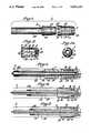
- FIG. 1is an exploded side elevational view of an epiphyseal/metaphyseal implant of the present invention including an expansion sleeve and an elongated plunger;
- FIG. 2is a longitudinal sectional view of the expansion sleeve of the implant of FIG. 1 in the rest position of the sleeve, taken along a plane including the longitudinal axis of the sleeve;
- FIG. 2Ais an end view of the expansion sleeve of FIG. 1 in the rest position of the sleeve;
- FIGS. 3 to 5are longitudinal sectional views of the implant of FIG. 1, taken along a plane including the common longitudinal axis of the plunger and sleeve, showing three stages in the insertion of the plunger into the sleeve held in a patient's bone;
- FIG. 6is a top plan view of a proximal angled side plate included in a modular implant system or kit of the invention.
- FIG. 7is a sectional view taken along line 7--7 of FIG. 6;
- FIG. 8is a sectional view taken along line 8--8 of FIG. 6;
- FIG. 9is a top plan view of an elongated bone plate included in a modular implant system of the invention.
- FIG. 10is a sectional view taken along line 10--10 of FIG. 9;
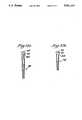
- FIGS. 11A and 11Bare side elevational views of a pair of cortical bone screws of different shank lengths included in a modular implant system of the invention.
- FIGS. 12A and 12Bare side elevational views of a pair of cancellous bone screws of different shank lengths included in a modular implant system of the invention.
- FIG. 13is an enlarged top plan view of each of the cortical bone screws of FIGS. 11A and 11B;
- FIG. 14is a sectional view taken along line 14--14 of FIG. 9 showing the permitted side-to-side angulation of one of the cortical bone screws of FIG. 11A within one of the bone screw-receiving apertures provided in the bone plate of FIG. 9;
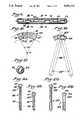
- FIG. 15is a lateral elevational view of the epiphyseal/metaphyseal implant of FIG. 1, the proximal angled side plate of FIG. 6, the elongated bone plate of FIG. 9 and a plurality of cortical bone screws of the type shown in FIGS. 11A and 11B, all connected together and secured to a patient's femur, with the femur shown partly in section;
- FIG. 16is a sectional view taken along line 16--16 of FIG. 15;
- FIG. 17is a sectional view taken along line 17--17 of FIG. 15;
- FIG. 18is a side elevational view of a surgical implant insertion instrument of the invention shown assembled with the expansion sleeve and elongated plunger of the implant of FIG. 1;
- FIG. 18Ais a sectional view taken along line 18A--18A of FIG. 18;
- FIG. 19is a side elevational view of an intramedullary rod having an anterior-posterior bow included in a modular implant system of the invention.
- FIG. 20is another side elevational view of the intramedullary rod of FIG. 19, as viewed in a direction perpendicular to that of FIG. 19;
- FIG. 21is a sectional view taken along line 21--21 of FIG. 19;
- FIG. 22is a longitudinal view, partially in section, of a proximal end region of an intramedullary rod of the type shown in FIG. 19, illustrating the optional feature of a detachable hollow sleeve secured to the proximal end portion of the intramedullary rod;
- FIG. 23is a top plan exploded view of an elongated intramedullary rod-epiphyseal/metaphyseal implant connection piece, locking screw and locking shoe included in a modular implant system of the invention;
- FIG. 24is a front view, partially in section, of the articles shown in FIG. 23;
- FIG. 25is an elevational view of an epiphyseal/metaphyseal implant of the type shown in FIG. 1 but of shorter length, the intramedullary rod of FIG. 19 and the connection piece, locking screw and locking shoe of FIG. 23, all connected together and secured to a patient's femur, with the femur shown in section, wherein the epiphyseal/metaphyseal implant and connection piece form together an elongated cross-member;
- FIG. 26is a bottom plan view of a distal angled side plate included in a modular implant system of the invention.
- FIG. 27is a sectional view taken along line 27--27 of FIG. 26;
- FIG. 28is an elevational view of an epiphyseal/metaphyseal implant of the type shown in FIG. 1 but of shorter length, the distal angled side plate of FIG. 26, the elongated bone plate of FIG. 9 and a plurality of cortical bone screws of the type shown in FIGS. 11A and 11B, all connected together and secured to a patient's femur, with the femur shown in section;
- FIG. 29is a top plan view of a distal buttress plate included in a modular implant system of the invention.
- FIG. 30is a side elevational view of the distal buttress plate of FIG. 29;
- FIG. 31is an elevational view of the distal buttress plate of FIG. 29, the elongated bone plate of FIG. 9 and a plurality of cortical and cancellous bone screws of the type shown in FIGS. 11A, 11B, 12A and 12B, all connected together and secured to a patient's distal femur, with the femur shown in section; and
- FIGS. 32A and 32Bare side elevational views of a pair of cortical bone screws of different shaft lengths suitable for use as distal locking screws.
- FIGS. 1 to 32B depicting various preferred embodiments of the inventionare made of a resilient, physiologically-inert titanium-base alloy.
- Implant 1comprises an integral substantially cylindrical expansion sleeve 3 and an elongated plunger 5.
- Sleeve 3includes a smoothly rounded circumferentially-closed dome 7 at one end, a circumferentially-closed circular ring 9 at the opposite end, and a plurality (eight in the embodiment shown in FIGS. 1 to 5) of identical substantially straight elongated thin resilient strips 11 extending between, and connected at their opposed ends by and to, dome 7 and ring 9.
- a centrally-disposed threaded axial through bore 15is provided in dome 7 for releasably securing an elongated insertion rod to the dome.
- Strips 11have textured outer surfaces to enhance the bone-gripping action of the implant and define together the cylindrical wall of sleeve 3, which sleeve wall has in the rest position of the sleeve an outer diameter essentially equal to the outer diameter of ring 9.
- each of the strips 11is of varying thickness along its length so that the sleeve wall has in the rest position of the sleeve an inner diameter in a region r 1 adjacent ring 9 equal to the inner diameter of ring 9 and an inner diameter in a region r 2 spaced from ring 9 reduced from the inner diameter of ring 9.
- the strips 11do not touch each other along their lengths in the rest position of the sleeve, but are instead separated by an equal number of longitudinal openings, e.g. 13.
- Plunger 5includes at one end thereof a substantially cylindrical body portion 17 having a diameter essentially equal to the inner diameter of ring 9 of sleeve 3, and a cylindrical stem portion 19 having a smaller diameter than body portion 17 extending from body portion 17 to the other end of the plunger. Plunger 5 is cannulated along its longitudinal axis, as shown in FIG. 1. An internally threaded recess 20 is provided at the trailing end of stem portion 19 for engagement with an externally threaded tool to remove plunger 5 from the patient's bone after implantation, if desired.
- the body portion 17 of plunger 5includes a raised annular lip 18 adjacent the trailing end of portion 17, a groove 10 is provided in the inner wall of ring 9 and a plurality (eight in the embodiment shown in FIGS. 1 to 5) of relatively short slots 12 (open at the trailing edge of ring 9) are provided in the closed ring 9, all for a purpose to be described below.
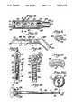
- FIGS. 3 to 5show how bone implant 1 is actuated to grip a patient's bone B at the leading end portion of the implant.
- the expansion sleeve 3is inserted into and held within a cylindrical cavity C in the patient's bone B by means of an insertion rod 21 having an externally threaded end portion 23 screwed into the internally threaded bore 15 of sleeve 3.
- Insertion rod 21extends along the longitudinal axis of sleeve 3 and is cannulated to fit over a guide wire 25.
- Cannulated plunger 5, which is in a sliding fit over rod 21,is advanced along rod 21 towards sleeve 3 (i.e. from left to right in FIG. 3) with its substantially cylindrical body portion 17 in the leading position.
- plunger 5After the body portion 17 of plunger 5 first contacts the elongated strips 11 at the beginning of region r 2 (see FIG. 4), the continued advancement of plunger 5 into the interior of sleeve 3 causes the eight strips 11 to expand radially outwardly against the wall of the cavity C and securely grip the patient's bone B.
- the plunger 5When the plunger 5 is fully advanced within the expansion sleeve 3 (see FIG. 5), the raised lip 18 fits into the groove 10 to lock the sleeve 3 and plunger 5 against an undesired axial disengagement after implantation of the implant 1.
- the equally-spaced (circumferentially) slots 12impart a slight resiliency to the ring 9 which allows the rib 18 to snap into the groove 10.
- the cylindrical wall of the sleeve 3has taken on a generally barrel-shaped contour, which results from the fact that the opposite ends of each strip 11 are fixed to dome 7 and ring 9, respectively. Since the expansion sleeve 3 is made of a resilient material the strips 11 expand radially outwardly in elastic deformation when the plunger 5 is fully advanced into the expansion sleeve 3. If desired, an extrudable bone cement or bone filler material can be inserted into the sleeve 3 so that when the plunger 5 is advanced into the sleeve 3 the bone cement or bone filler is extruded through the openings 13 to the sleeve-bone interface.
- Insertion instrument 27for use in the implantation of bone implant 1 is shown in FIG. 18 assembled with sleeve 3 and plunger 5.
- Insertion instrument 27includes the elongated axially-cannulated insertion rod 21 (upon which plunger 5 can slide) having an externally threaded end portion 23 adapted to be screwed into threaded bore 15 in dome 7 of sleeve 3 and an externally smooth portion 29 extending from the threaded portion 23, a hollow sleeve 31 capable of sliding movement upon smooth portion 29, a handle 33 and a means 35 for advancing the hollow sleeve 31 along the smooth portion 29 of rod 21 towards the externally threaded portion 23 of rod 21.
- the sleeve advancing means 35comprises a knurled knob 37 threaded upon an externally threaded portion 39 of the elongated rod 21. As knob 37 is turned it pushes against sleeve 31. Preferably, a nylon washer (not shown in the figures) is fitted between knob 37 and sleeve 31. A guide pin 41 provided on the inner wall of sleeve 31 is received within a longitudinal groove provided in threaded portion 39 (see FIG. 18A). In use, the surgeon holds handle 33 in one hand and turns knob 37 with the other hand to advance hollow sleeve 31 toward the expansion sleeve 3.
- the hollow sleeve 31abuts the plunger 5, which is also fitted on the insertion rod 21, and thus in turn forces plunger 5 along the rod until the plunger is advanced into the expansion sleeve 3.
- the surgeoncan stop advancement of the plunger into the expansion sleeve (to rest, to assess the surgical situation, or for any other reason) without relaxing the force being placed on the plunger by the insertion instrument 27. In such a situation movement of hollow sleeve 31 and plunger 5 along insertion rod 21 away from expansion sleeve 5 is positively prevented by the structure of the sleeve advancing means 35.
- the guide wire 25 and the insertion rod 21are removed from the patient's bone, although it is contemplated that an appropriately dimensioned insertion rod and/or guide wire might be left in place in the patient's bone to form a part of the implanted elongated bone implant.
- Proximal angled side plate 43which may be included in a modular implant system or kit of the invention is shown in FIGS. 6 and 7.
- Proximal angled side plate 43includes an elongated plate portion 45 adapted to be secured to the outer cortical wall of the femoral shaft and an integral hollow sleeve 47 extending from one end of plate portion 45.
- the elongated plate portion 45has an upper surface 49 and a lower surface 51 intended to be adjacent the patient's bone in use, while the hollow sleeve 47 is provided with a longitudinal cylindrical through bore 53 extending from upper surface 49 to the free end of hollow sleeve 47. As shown in FIG.
- the elongated plate portion 45 and hollow sleeve 47are oriented at an oblique angle of about 130°-150° so that hollow sleeve 47 is adapted to extend into the intertrochanteric region of the femur when elongated plate portion 45 is secured to the outer cortical wall of the adjacent femoral shaft.
- the term "adapted to be secured to the outer cortical wall" of a bonemeans that an implant is adapted to be secured to a bone in such a way that it abuts the outer cortical wall of the bone.
- an implantmay be provided with a plurality of apertures along its length for the receipt of bone fasteners (e.g. bone screws, nails, pins, bolts, rivets, or the like) used to secure the implant to the outer cortical wall.
- three circular through apertures 55, 57 and 59are provided in the elongated plate portion 45 of the proximal angled side plate 43 for the receipt of three bone screws, one in each aperture. These three apertures are staggered with respect to the longitudinal axis of plate portion 45 (see FIG. 6) in order to reduce stress concentrations in the secured plate portion and in the bone.
- the upper portions 61 of the walls of apertures 55, 57 and 59 adjacent upper surface 49are preferably identical, concave-upward spherical surfaces. These identical spherical surfaces are adapted for cooperation with spherically-headed cortical and cancellous bone screws, as is discussed below.
- elongated cavity 63formed in the lower surface 51 of plate portion 45, which cavity extends longitudinally from the free end 65 of plate portion 45 to a shoulder 67.
- Cavity 63is adapted to receive an end portion of an elongated bone plate of the invention in a sliding fit, as will be described below.
- the lower surface 51 of elongated plate portion 45is slightly curved (as viewed in transverse cross-sections of plate portion 45 (see FIG. 8)) to conform to the outer cortical wall of a femur.
- Bone plate 69 of the inventionadapted to be secured to a patient's bone is shown in FIGS. 9 and 10.
- Bone plate 69has an upper surface 71, a lower surface 73 intended to be adjacent the patient's bone in use and two side surfaces 75 and 77 connecting surfaces 71 and 73.
- Bone plate 69is provided with for example six identical elongated through apertures, e.g. 79, 80 and 85, for the receipt of bone screws used to secure the plate to a patient's bone, e.g. to the outer cortical wall of the femoral shaft. Some other number (odd or even) of elongated through apertures than six may be provided in the bone plate of the invention, if desired.
- the elongated aperturesare alternately offset from the longitudinal axis of the bone plate (see FIG. 9) in order to reduce stress concentrations in the secured bone plate and in the bone and the separation between the two centermost slots (e.g. the third and fourth slots in FIG. 9) is greater than the separation between other pairs of adjacent slots.
- the width of upper surface 71is greater than the width of lower surface 73
- side surfaces 75 and 77are tapered inwardly toward one another in the direction from surface 71 to surface 73 (i.e. downwardly and inwardly in FIG. 10)
- the thickness T of the bone plate 69is substantially constant across the bone plate from side surface 75 to side surface 77.
- bone plate 69includes two parallel rails 81 and 83 located at the opposite sides of lower surface 73, which rails extend along substantially the entire length of plate 69. In use, only rails 81 and 83 contact the surface of the patient's bone to minimize interference with bone or periosteal vascularity.
- bone plate 69its transverse cross-sectional dimensions are complementary to those of the cavity 63 in the elongated plate portion 45 of the proximal angled side plate 43.
- either end of bone plate 69can be inserted into cavity 63, but because of the tapered side surfaces of the bone plate and cavity the bone plate 69 can enter and be removed from the cavity 63 only by relative axial movement through the opening of cavity 63 at the free end 65 of plate portion 45. Separation or joining by relative movement in the vertical direction is not permitted and the bone plate 69 cannot rotate with respect to the proximal angled side plate 43 when it is inserted within the cavity 63 (see FIG.
- three bone plates of varying length of the type shown in FIG. 9are provided, having four, six and eight elongated apertures respectively, for use either independently or to extend the length of side plates.
- Elongated bone plate 69may also be used by itself as a conventional bone plate in the treatment of, for example, diaphyseal femoral fractures.
- the six apertures in the plateare elongated to be able to receive either one or two screws each in use.
- the upper portions 107, adjacent upper surface 71, of the identical aperturesare spherically-rounded concave-upward all the way around the aperture. These identical spherically-rounded surfaces are adapted for cooperation with spherically-headed cortical and cancellous bone screws, as is discussed below.
- Bone plate 69is preferably slightly curved (as viewed in transverse cross-sections such as FIG. 10) to conform to the shape of the human femoral shaft.
- upper surface 71 and lower surface 73are defined in transverse bone plate cross-sections by arcs of two concentric circles having a center O, while side surfaces 75 and 77 are defined by two straight lines which, when extended, pass through center O and form together an angle A.
- FIGS. 11A and 11BA pair of self-tapping cortical bone screws 89 and 91 which may be included in a modular implant system of the invention are shown in FIGS. 11A and 11B. Screws 89 and 91 have identical heads 93 and identical shanks 97 and 99 externally threaded along essentially the entire shank length, with the single exception that shank 97 of screw 89 is longer than shank 99 of screw 91.
- FIGS. 12A and 12BA pair of self-tapping cancellous bone screws 101 and 103 which may be included in a modular implant system of the invention are shown in FIGS. 12A and 12B.
- the heads 93 of screws 101 and 103are identical to the heads of cortical screws 89 and 91, while the shanks of cancellous screws 101 and 103, which are externally threaded adjacent the free shank end only, are identical with the single exception that the shank of screw 101 has a longer unthreaded portion than the shank of screw 103.
- Another pair of self-tapping cortical bone screws 90 and 92are shown in FIGS. 32 and 32A. These screws are identical to screws 89 and 91 except that a portion of the shanks of screws 90 and 92 is not threaded. As is shown in FIG.
- an identical axially-extending recess 95 having parallel axially-extending wallsis provided in each of the identical heads 93 of screws 89, 91, 90, 92, 101 and 103 for the receipt of a screw-driving instrument (e.g. a screwdriver).
- the recessis generally star-shaped in cross-section, e.g. the generally star-shaped Torx (TM)-drive cross-section shown in FIG. 13 or the generally star-shaped cross-section of a Pozidriv (TM) recess.
- the cortical and/or cancellous bone screwsmay be reduced in one or more steps in diameter or tapered towards the free shank end for increasing grip strength on the neighboring femoral cortex.
- FIG. 14shows the permitted side-to-side angulation of one of the four screws of FIGS. 11A, 11B, 12A and 12B (shown in phantom lines) within one of the screw-receiving apertures (i.e. aperture 80) provided in the bone plate 69.
- screw 89is capable of rotating through an angle of about 30° in a plane perpendicular to the longitudinal axis of bone plate 69.
- unrestricted angulationis permitted in a plane parallel to the longitudinal axis of the bone plate.
- unrestricted angulationis permitted in one direction only in a plane parallel to the longitudinal axis of the bone plate while only about a 15° rotation from the vertical is permitted in the opposite direction in said plane.
- the radius of the spherically-rounded surface of the upper portion 61 of the apertures 55, 57 and 59 in the angled side plate 43is equal to the radius in the transverse plane of FIG. 14 of the surface of the upper portion 107 of aperture 80 of bone plate 69.
- screws 89, 91, 101 and 103are capable of a universal rotation with respect to the elongated plate portion 45 within a cone having an apex angle of about 30° when fully advanced within one of the apertures 55, 57 and 59.
- Elongated epiphyseal/metaphyseal implant 1, proximal angled side plate 43, elongated bone plate 70 having four elongated apertures and a plurality of the cortical bone screws 89can be connected together and secured to a patient's right femur F in the manner shown in FIGS. 15 to 17 to form an angled side plate-hip pin assembly with the effective length of the elongated plate portion of the angled side plate extended by the elongated bone plate.
- the implant 1is first implanted within a cavity prepared in the proximal femur, which cavity must be widened adjacent its open end to accommodate hollow sleeve 47, said sleeve 47 of side plate 43 is then inserted into the cavity so that a portion of the cylindrical stem portion 19 of plunger 5 is received in a sliding fit within the cylindrical bore 53 of sleeve 47, one end of bone plate 70 is slid into cavity 63 of side plate 43 until it abuts shoulder 67, and the entire assembly is then secured to the femur F with a plurality of cortical bone screws 89 passed through apertures in side plate 43 and bone plate 70.
- one or more conventional fixation pinse.g.
- Bone plate 70can, of course, be omitted from the assembly of FIG. 16 if the length of plate portion 45 is sufficient without extension in a particular surgical situation.
- a femoral intramedullary rod 109which may be included in a modular implant system or kit of the invention is shown in side elevational views in FIGS. 19 and 20 as viewed in perpendicular directions.
- Rod 109has a proximal end 111 and a distal end 113 and a pair of transverse through bores 115 adjacent distal end 113 to receive bone screws 90.
- One or two through bores 116 to receive locking bone screwsmay also be included adjacent proximal end 111.
- Rod 109has a distal end portion 117 and a straight proximal end portion 119. As is shown in FIG.
- rod 109has a slight bow, which is intended to lie in the anterior-posterior plane of the femur after implantation; no such bow is exhibited in FIG. 20, since rod 109 is intended to be straight in the lateral-medial plane after implantation.
- the transverse cross-section of rod 109is shown in FIG. 21.
- This cross-sectionhas a closed profile, with the outer periphery of the cross-section being a plurality of (e.g. six) smoothly rounded peaks (e.g. 121), all terminating on the same first circle, connected by an equal number of smoothly rounded valleys (e.g. 123), all bottoming on the same second circle concentric with and of smaller diameter than said first circle.
- FIG. 21provides for extensive re-vascularization of the bone tissue of the intramedullary canal wall following reaming.
- FIG. 21also shows that rod 109 is axially cannulated, with an axial bore 125 extending from the distal tip 127 of hollow rod 109 to the proximal tip 129 of the rod.
- a diametrical slot 120is provided at proximal tip 129 for engagement with appropriate insertion and extraction tools.
- connection piece 139An elongated connection piece 139, locking screw 141 and locking shoe 142 for connecting an epiphyseal/metaphyseal implant 1 to intramedullary rod 109 adjacent to the proximal end 111 of rod 109 to form a Y-nail type of assembly are shown in FIGS. 23 and 24.
- Connection piece 139is provided at one end with an elongated cylindrical cavity 143 aligned with the longitudinal axis of piece 139 and adapted to receive the free end of stem portion 19 of plunger 5 of implant 1 in a sliding fit.
- Connection piece 139is also provided with a cylindrical through bore 145 disposed at an oblique angle of about 135° with respect to said longitudinal axis, and an elongated partially countersunk and partially internally-threaded bore 147 aligned with said longitudinal axis at the end of the elongated connection piece 139 opposite to cavity 143.
- Bore 147is adapted to receive locking screw 141 and locking shoe 142, and both bore 147 and cavity 143 open into through bore 145.
- connection piece 139 and intramedullary rod 109can be securely locked against relative translational and rotational movement by screwing locking screw 141 forward in the partially threaded bore 147 behind the locking shoe 142 until the leading surface 144 of locking shoe 142 very firmly presses against the surface of proximal end portion 119, and then unlocked again if desired simply by unscrewing screw 141.
- the leading surface 144 of locking shoe 142has a grooved contour adapted to fit closely and mesh with the splined external contour of rod 109, thereby enhancing the secure locking of rod 109 to the connection piece 139.
- Locking screw 141 and locking shoe 142are assembled together in use, e.g. by a captured thread or staked head connection, to cause withdrawal of shoe 142 when screw 141 is unscrewed while permitting independent relative rotation between these two element during screwing and unscrewing of screw 141.
- a hollow sleeve 131 having a smooth cylindrical outer surfaceis detachably secured to the exterior of the proximal end portion 119 of intramedullary rod 109 (having the fluted cross-section of FIG. 21) by means of a locking screw 135 having a head and an externally threaded shank fitted through a centrally-disposed opening in the top wall of sleeve 131 and threaded into an internally-threaded centrally-disposed bore 137 at the top of rod 109.
- An advantage of the embodiment of FIG. 22is that the diameter of the straight proximal end of rod 109 is effectively increased above that of the maximum transverse dimension in the transverse cross-section of FIG. 21.
- the hollow sleeve 131should extend distally at least to the point of maximum applied bending moment in normal use, which point of maximum bending moment is usually in the subtrochanteric region of the femur, but not all the way to the midway point along the length of rod 109 between the distal and proximal tips 127 and 129 of the rod.
- the contour of the leading surface of locking shoe 142should be adapted accordingly, or alternatively, the locking shoe can be eliminated and the locking screw used alone.
- Intramedullary rod 109, connection piece 139, locking screw 141, locking shoe 142 and a bone implant 1can be connected together in the manner shown in FIG. 25 to form a Y-nail type of assembly in a femur F, with implant 1 and piece 139 forming together the elongated cross-member of the Y-nail.
- the epiphyseal/metaphyseal implant 1is first implanted into a cavity prepared in the proximal femur, which cavity must be widened adjacent its open end to accommodate the connection piece 139.
- Piece 139is then advanced into the prepared bone cavity and oriented so that a portion of stem portion 19 of plunger 5 is received in a sliding fit within cavity 143 and through bore 145 is in approximate alignment with the femoral intramedullary canal.
- Rod 109is advanced distally through an opening prepared by conventional means in the proximal femur wall and through the through bore 145 in piece 139 until the distal end portion 117 of rod 109 is in the distal femur and the proximal end portion 119 of the rod 109 is within the through bore 145.
- connection piece 139is then carefully adjusted to the desired disposition, and connection piece 139 is then locked to intramedullary rod 109 by means of the locking screw 141 and locking shoe 142.
- a cortical bone screw 90 of the type shown in FIG. 32A of large shank lengthcan be inserted by conventional methods through one or both of the transverse bores 115 to lock the rod 109 to the distal femur.
- cap screw 135may be screwed into bore 137, even when sleeve 131 is not being used, to prevent bone ingrowth into the threads in bore 137.
- connection piece similar to piece 139could be used, if desired, to connect an epiphyseal/metaphyseal implant similar to implant 1 to the distal end portion 117 of intramedullary rod 109, with the epiphyseal/metaphyseal implant residing in the distal condylar region of the femur and being substantially perpendicular to said portion 117.
- the through bore of the connection piece analogous to through bore 145 in piece 139would be substantially perpendicular to the longitudinal axis of the connection piece.
- Distal angled side plate 149which may be included in a modular implant system or kit of the invention is shown in FIGS. 26 and 27.
- Distal angled side plate 149includes an elongated plate portion 151 adapted to be secured to the outer cortical wall of the distal femoral shaft and an integral hollow sleeve 153 extending from one end of plate portion 151.
- the plate portion 151is slightly angulated in the vicinity of line R in order to accommodate the commencement of the anatomical bulge of the lateral distal femur.
- the elongated plate portion 151has an upper surface 155 and a lower surface 157 intended to be adjacent the patient's bone in use, while the hollow sleeve 153 is provided with a longitudinal cylindrical through bore 159 extending from upper surface 155 to the free end of hollow sleeve 153. As shown in FIG. 27, the elongated plate portion 151 and hollow sleeve 153 are substantially perpendicular so that hollow sleeve 153 is adapted to extend into the distal condylar region of the femur when elongated plate portion 151 is secured to the outer cortical wall of the adjacent distal femoral shaft.
- Through bore 159is dimensioned to receive a portion of the stem portion 19 of the plunger 5 of an elongated epiphyseal/metaphyseal implant 1 in a sliding fit.
- the lower surface 157is slightly curved in transverse cross-section in a similar manner as shown in FIG. 8 (for the proximal side plate 43) to conform to the outer cortical wall of a distal femur.
- Three circular through apertures 161, 163 and 165are provided in plate portion 151 for the receipt of three bone screws (e.g. cortical screw 89), one in each aperture. These three apertures are staggered with respect to the longitudinal axis of plate portion 151 (see FIG. 26) in order to reduce stress concentrations in the secured plate portion and in the bone.
- Apertures 161, 163 and 165are identical respectively to apertures 55, 57 and 59 in the proximal angled side plate 43.
- the distal angled side plate 149is also provided with an elongated cavity 167 formed in the lower surface 157 of plate portion 151. Cavity 167 is identical to cavity 63 in the proximal angled side plate 43.
- cavity 167is adapted to receive either end of elongated bone plate 69 in a "dovetail" interlocked sliding fit (see FIG. 17), and when the end of the bone plate abuts shoulder 169 apertures 163 and 165 overlie the two terminal apertures, e.g. apertures 79 and 85 respectively, in the bone plate 69.
- the distal angled side plate 149, an elongated epiphyseal/metaphyseal implant 1 and a plurality of the cortical bone screws 89can be connected together and secured to a patient's femur F in the manner shown in FIG. 28 to form a distal side plate-pin assembly with the effective length of the elongated plate portion of the side plate extended by the elongated bone plate.
- the preferred surgical procedureis analogous to the one described above with regard to the assembly of FIGS. 15 and 16.
- Bone plate 69can, of course, be omitted from the assembly of FIG. 28 if the length of plate portion 151 is sufficient without extension in a particular surgical situation.
- a distal buttress plate 171 of the invention adapted to be secured to the outer cortical wall of the lateral distal femuris shown in FIGS. 29 and 30.
- Buttress plate 171includes a relatively flat elongated proximal portion 173 adapted to be secured to the lateral distal femoral shaft and a three dimensionally-contoured distal portion 175 designed to replicate the mean geometry of the lateral femoral condyle of adult humans.
- the distal portion 175includes a generally rounded head 177 at the distal end of plate 171, a generally widened body 179 having a greater maximum width than both head 177 and proximal portion 173, and a neck 181 having a minimum width W substantially smaller than the maximum widths of head 177 and body 179.
- the lower surface of the distal buttress plate 171is contoured along its entire length to conform to the outer cortical wall of the distal femur.
- Distal buttress plate 171is adapted to be secured to the outer cortical wall of the lateral distal femur by means of bone screws received in apertures in the plate.
- three circular through apertures 183, 185 and 187are provided in proximal portion 173 for the receipt of three bone screws (e.g. cortical screw 89), one in each aperture.
- These three aperturesare staggered with respect to the longitudinal axis of proximal portion 173 (see FIG. 29), and are identical respectively to apertures 55, 57 and 59 in the angled side plate 43.
- an elongated aperture 189is provided in head 177 and two elongated apertures 191 and 193 are provided in body 179, one on each side of body 179.
- Each of apertures 189, 191 and 193is substantially identical to the apertures in the elongated bone plate 69 and thus are each configured to receive two (or one, if only one is desired) bone screws having a head 93 and permit the universal angulation of said screws when fully advanced in the aperture.
- distal buttress plate 171is configured in such a manner that spaces outside the periphery of plate 171 are left against neck 181 for the accommodation of two fracture reduction lag screws, extending across the distal condylar region of the femur, on the two sides of neck 181. These two lag screws are shown in phantom in FIG. 29 as elements 195 and 197.
- the distal buttress plate 171is also provided with an elongated cavity 199 formed in the lower surface of the proximal portion 173.
- Cavity 199is identical to, and is adapted to serve in the same bone plate-"dovetail" interlocking capacity as, cavity 63 in the angled side plate 43 and cavity 167 in the angled side plate 149.
- Distal buttress plate 171, elongated bone plate 69, a plurality of cortical bone screws such as screw 89 and a plurality of cancellous bone screws such as screw 101can be connected together and secured to a patient's femur F in the manner shown in FIG. 31.
- two lag screws(not shown in FIG. 31) are fully implanted in the distal condylar region, if desired, to reduce a fracture in said region.
- These implanted lag screwsare positioned so that they lie generally in the lateral-medial plane and are spaced so that they will lie in close proximity to the two opposite sides of the neck 181 of portion 175 (see FIG. 29).
- the distal buttress plate 171is then secured to the lateral femur, with neck 181 fitting between the two previously implanted fracture reduction lag screws, by means of bone screws 101 passing through apertures 189, 191 and 193 (one or two screws can be passed through each of apertures 189, 191 and 193, as desired) and a bone screw 89 passed through aperture 183.
- Bone plate 69is then slid into cavity 199 until its end abuts shoulder 201 and bone screws 89 are screwed to the femur F through apertures 185 and 187. Finally, bone screws 89 are screwed to the femur F through some or all of the four apertures of bone plate 69 remaining outside of the cavity 199.
- Distal buttress plate 171can, of course, be implanted without bone plate 69 if the length of the proximal portion 173 is sufficient without extension for a particular surgical situation.
Landscapes
- Health & Medical Sciences (AREA)
- Orthopedic Medicine & Surgery (AREA)
- Surgery (AREA)
- Life Sciences & Earth Sciences (AREA)
- Veterinary Medicine (AREA)
- Nuclear Medicine, Radiotherapy & Molecular Imaging (AREA)
- Engineering & Computer Science (AREA)
- Biomedical Technology (AREA)
- Heart & Thoracic Surgery (AREA)
- Medical Informatics (AREA)
- Molecular Biology (AREA)
- Animal Behavior & Ethology (AREA)
- General Health & Medical Sciences (AREA)
- Public Health (AREA)
- Neurology (AREA)
- Surgical Instruments (AREA)
- Prostheses (AREA)
- Massaging Devices (AREA)
- Materials For Medical Uses (AREA)
- Paper (AREA)
- Polymerisation Methods In General (AREA)
- Dowels (AREA)
- Pharmaceuticals Containing Other Organic And Inorganic Compounds (AREA)
- Steroid Compounds (AREA)
- Polishing Bodies And Polishing Tools (AREA)
- Materials For Photolithography (AREA)
- Orthopedics, Nursing, And Contraception (AREA)
- Clamps And Clips (AREA)
- Television Systems (AREA)
Abstract
Description
Claims (13)
Priority Applications (3)
| Application Number | Priority Date | Filing Date | Title |
|---|---|---|---|
| US07/670,839US5190544A (en) | 1986-06-23 | 1991-03-18 | Modular femoral fixation system |
| US07/948,193US5364398A (en) | 1986-06-23 | 1992-09-21 | Modular femoral fixation system |
| US08/761,476US5772662A (en) | 1986-06-23 | 1996-12-06 | Femoral fixation system |
Applications Claiming Priority (4)
| Application Number | Priority Date | Filing Date | Title |
|---|---|---|---|
| US06/877,626US4776330A (en) | 1986-06-23 | 1986-06-23 | Modular femoral fixation system |
| JP62182098AJP2766641B2 (en) | 1986-06-23 | 1987-07-21 | Kit used to treat femoral disorders |
| JP9152294AJP2866839B2 (en) | 1986-06-23 | 1997-06-10 | Bone implant |
| JP25016598AJP3155515B2 (en) | 1986-06-23 | 1998-09-03 | Bone treatment fixation device |
Related Parent Applications (1)
| Application Number | Title | Priority Date | Filing Date |
|---|---|---|---|
| US06/877,626DivisionUS4776330A (en) | 1986-06-23 | 1986-06-23 | Modular femoral fixation system |
Related Child Applications (1)
| Application Number | Title | Priority Date | Filing Date |
|---|---|---|---|
| US07/670,839DivisionUS5190544A (en) | 1986-06-23 | 1991-03-18 | Modular femoral fixation system |
Publications (1)
| Publication Number | Publication Date |
|---|---|
| US5041114Atrue US5041114A (en) | 1991-08-20 |
Family
ID=27473141
Family Applications (4)
| Application Number | Title | Priority Date | Filing Date |
|---|---|---|---|
| US06/877,626Expired - LifetimeUS4776330A (en) | 1986-06-23 | 1986-06-23 | Modular femoral fixation system |
| US07/232,188Expired - LifetimeUS5041114A (en) | 1986-06-23 | 1988-08-15 | Modular femoral fixation system |
| US07/948,193Expired - LifetimeUS5364398A (en) | 1986-06-23 | 1992-09-21 | Modular femoral fixation system |
| US08/761,476Expired - Fee RelatedUS5772662A (en) | 1986-06-23 | 1996-12-06 | Femoral fixation system |
Family Applications Before (1)
| Application Number | Title | Priority Date | Filing Date |
|---|---|---|---|
| US06/877,626Expired - LifetimeUS4776330A (en) | 1986-06-23 | 1986-06-23 | Modular femoral fixation system |
Family Applications After (2)
| Application Number | Title | Priority Date | Filing Date |
|---|---|---|---|
| US07/948,193Expired - LifetimeUS5364398A (en) | 1986-06-23 | 1992-09-21 | Modular femoral fixation system |
| US08/761,476Expired - Fee RelatedUS5772662A (en) | 1986-06-23 | 1996-12-06 | Femoral fixation system |
Country Status (14)
| Country | Link |
|---|---|
| US (4) | US4776330A (en) |
| EP (6) | EP0464961B1 (en) |
| JP (3) | JP2766641B2 (en) |
| AT (5) | ATE151253T1 (en) |
| AU (8) | AU7460487A (en) |
| CA (1) | CA1321677C (en) |
| DE (7) | DE3751381T2 (en) |
| DK (4) | DK170628B1 (en) |
| ES (5) | ES2043657T3 (en) |
| GR (3) | GR3017130T3 (en) |
| IE (1) | IE63434B1 (en) |
| NO (1) | NO165176C (en) |
| PT (1) | PT85143B (en) |
| ZA (1) | ZA874489B (en) |
Cited By (238)
| Publication number | Priority date | Publication date | Assignee | Title |
|---|---|---|---|---|
| US5167663A (en)* | 1986-12-30 | 1992-12-01 | Smith & Nephew Richards Inc. | Femoral fracture device |
| US5312406A (en)* | 1986-12-30 | 1994-05-17 | Smith & Nephew Richards Inc. | Method of treating an intertrochanteric fracture |
| EP0668059A1 (en)* | 1994-02-21 | 1995-08-23 | Collux AB | Implant for treating fractures of the femur |
| US5458654A (en)* | 1993-07-14 | 1995-10-17 | Ao-Forschungsinstitut Davos | Screw-fixed femoral component for hip joint prosthesis |
| US5484439A (en)* | 1992-09-16 | 1996-01-16 | Alphatec Manufacturing, Inc. | Modular femur fixation device |
| WO1997008999A1 (en)* | 1995-09-08 | 1997-03-13 | Depuy Ace Medical Company | Internal bone fracture fixator |
| US5665089A (en)* | 1992-03-19 | 1997-09-09 | Dall; Desmond Meiring | Bone fixation system |
| US5702396A (en)* | 1995-03-27 | 1997-12-30 | Hoenig; Johannes Franz | Osteosynthesis plate |
| US5749872A (en)* | 1995-09-08 | 1998-05-12 | Ace Medical Company | Keyed/keyless barrel for bone plates |
| US5776194A (en)* | 1996-04-25 | 1998-07-07 | Nuvana Medical Innovations, Llc | Intermedullary rod apparatus and methods of repairing proximal humerus fractures |
| WO1998034555A1 (en) | 1997-02-11 | 1998-08-13 | Orthomatrix, Inc. | Modular intramedullary fixation system and insertion instrumentation |
| US5849004A (en)* | 1996-07-17 | 1998-12-15 | Bramlet; Dale G. | Surgical anchor |
| US5938664A (en)* | 1998-03-31 | 1999-08-17 | Zimmer, Inc. | Orthopaedic bone plate |
| US5951557A (en)* | 1997-12-30 | 1999-09-14 | Luter; Dennis W. | Bone plate |
| US6004324A (en)* | 1996-11-22 | 1999-12-21 | Howmedica Gmbh | Adjustable locking nail |
| US6221074B1 (en)* | 1999-06-10 | 2001-04-24 | Orthodyne, Inc. | Femoral intramedullary rod system |
| RU2176907C2 (en)* | 1999-10-13 | 2001-12-20 | Галикеев Марат Фаритович | Device for carrying out vertebral column osteosynthesis |
| RU2177278C2 (en)* | 1998-03-31 | 2001-12-27 | Новосибирский научно-исследовательский институт травматологии и ортопедии | Interbody fixative for surgical treatment of lumbar intervertebral osteochondrosis |
| US6379360B1 (en) | 1998-03-11 | 2002-04-30 | Synthes (Usa) | Spiral blade insertion instrument |
| US6443954B1 (en) | 2001-04-24 | 2002-09-03 | Dale G. Bramlet | Femoral nail intramedullary system |
| US6447546B1 (en) | 2000-08-11 | 2002-09-10 | Dale G. Bramlet | Apparatus and method for fusing opposing spinal vertebrae |
| US20020156474A1 (en)* | 2001-04-20 | 2002-10-24 | Michael Wack | Polyaxial locking plate |
| RU2200496C2 (en)* | 1999-02-01 | 2003-03-20 | Дагестанская государственная медицинская академия | Apparatus for treating calcaneus fracture |
| US20030074000A1 (en)* | 2001-10-17 | 2003-04-17 | Roth Christoph Andreas | Bone fixation system |
| US6562042B2 (en) | 2000-02-02 | 2003-05-13 | Owen A. Nelson | Orthopedic implant used to repair intertrochanteric fractures and a method for inserting the same |
| US6623486B1 (en) | 1999-09-13 | 2003-09-23 | Synthes (U.S.A.) | bone plating system |
| US6648889B2 (en) | 2001-04-24 | 2003-11-18 | Dale G. Bramlet | Intramedullary hip nail with bifurcated lock |
| US6669700B1 (en) | 1997-05-15 | 2003-12-30 | Sdgi Holdings, Inc. | Anterior cervical plating system |
| US20040127898A1 (en)* | 2002-11-04 | 2004-07-01 | Michael Adam | Bone fixing system |
| US20040181228A1 (en)* | 1999-03-09 | 2004-09-16 | Synthes Ag Chur And Synthes (Usa) | Bone plante |
| US20040204712A1 (en)* | 2003-04-09 | 2004-10-14 | Eric Kolb | Bone fixation plates |
| US20040204716A1 (en)* | 2003-04-09 | 2004-10-14 | Jonathan Fanger | Drill guide with alignment feature |
| US20040267274A1 (en)* | 2003-06-27 | 2004-12-30 | Tushar Patel | Tissue retractor and drill guide |
| US20050059970A1 (en)* | 2003-09-17 | 2005-03-17 | Eric Kolb | Bone fixation systems |
| US20050261688A1 (en)* | 2004-05-11 | 2005-11-24 | Grady Mark P Jr | Bone plate |
| US20060064095A1 (en)* | 2003-03-07 | 2006-03-23 | Peter Senn | Locking screw for an intramedullary nail |
| US7018380B2 (en) | 1999-06-10 | 2006-03-28 | Cole J Dean | Femoral intramedullary rod system |
| US20060149248A1 (en)* | 2003-06-12 | 2006-07-06 | Andre Schlienger | Surgical nail |
| US20060161155A1 (en)* | 2003-06-12 | 2006-07-20 | Andre Schlienger | Surgical nail |
| US20060173458A1 (en)* | 2004-10-07 | 2006-08-03 | Micah Forstein | Bone fracture fixation system |
| US20060189987A1 (en)* | 2002-05-30 | 2006-08-24 | Orbay Jorge L | Nail plate |
| US20060189988A1 (en)* | 2003-07-30 | 2006-08-24 | Andre Schlienger | Surgical nail |
| WO2005074580A3 (en)* | 2004-02-02 | 2006-08-31 | Acumed Llc | Bone plate with toothed aperture |
| US20060200157A1 (en)* | 2005-01-28 | 2006-09-07 | Orbay Jorge L | Nail Plate and Jig Therefor |
| US20060217722A1 (en)* | 2003-09-08 | 2006-09-28 | Christof Dutoit | Bone-fixation device |
| US20060229619A1 (en)* | 2005-03-17 | 2006-10-12 | Orbay Jorge L | Modular fracture fixation plate system with multiple metaphyseal and diaphyseal plates |
| US20060235400A1 (en)* | 2003-08-26 | 2006-10-19 | Rolf Schneider | Bone plate |
| US20060235395A1 (en)* | 2003-08-29 | 2006-10-19 | Robert Frigg | Intramedullary nail |
| US20060241605A1 (en)* | 2003-10-21 | 2006-10-26 | Andre Schlienger | Intramedullary nail |
| US20060264947A1 (en)* | 2005-05-20 | 2006-11-23 | Orbay Jorge L | Bone fixation system |
| US20070016205A1 (en)* | 2003-10-30 | 2007-01-18 | Florian Beutter | Bone plate |
| US20070055253A1 (en)* | 2005-03-17 | 2007-03-08 | Orbay Jorge L | Modular Fracture Fixation System |
| US20070093899A1 (en)* | 2005-09-28 | 2007-04-26 | Christof Dutoit | Apparatus and methods for treating bone |
| US7229445B2 (en) | 2004-06-21 | 2007-06-12 | Synthes (Usa) | Bone plate with bladed portion |
| US20070156144A1 (en)* | 2004-06-24 | 2007-07-05 | Dieter Ulrich | Intramedullary nail |
| US20070173838A1 (en)* | 2006-01-12 | 2007-07-26 | Kung-Chia Li | Femoral head and neck strengthening device |
| US20070225819A1 (en)* | 2006-03-24 | 2007-09-27 | Depuy Products, Inc. | Apparatus and method for the treatment of periprosthetic fractures |
| US20070270845A1 (en)* | 2003-09-08 | 2007-11-22 | Kohsuke Watanabe | Orthopaedic plate and screw assembly |
| US20070270846A1 (en)* | 2006-03-31 | 2007-11-22 | Metzinger Anthony J | Fixture, intramedullary nail kit and method of presetting a nail assembly |
| US20070288019A1 (en)* | 2004-06-22 | 2007-12-13 | Andre Schlienger | Intramedullary Nail |
| RU2312634C1 (en)* | 2006-04-12 | 2007-12-20 | Федеральное государственное учреждение "Российский научно-исследовательский институт травматологии и ортопедии им. Р.Р. Вредена" Федерального агентства по здравоохранению и социальному развитию (ФГУ "РНИИТО им. Р.Р. Вредена" Росздрава) | Fork-like plate for carrying out tibial condyle fracture osteosynthesis |
| US20070299447A1 (en)* | 2003-09-08 | 2007-12-27 | Kohsuke Watanabe | Orthopaedic plate and screw assembly |
| US20080004623A1 (en)* | 2003-09-08 | 2008-01-03 | Joseph Ferrante | Orthopaedic Implant and Screw Assembly |
| US20080039845A1 (en)* | 2006-02-07 | 2008-02-14 | Bonutti Peter M | Methods and devices for intracorporeal bonding of implants with thermal energy |
| US7354441B2 (en) | 2000-01-27 | 2008-04-08 | Synthes (U.S.A.) | Bone plate |
| US20080140130A1 (en)* | 2004-01-26 | 2008-06-12 | Chan Jason S | Highly-versatile variable-angle bone plate system |
| US20080183171A1 (en)* | 2007-01-26 | 2008-07-31 | Ebi, L.P. | Lockable intermedullary fixation device |
| US7410488B2 (en) | 2005-02-18 | 2008-08-12 | Smith & Nephew, Inc. | Hindfoot nail |
| US7416553B2 (en) | 2003-04-09 | 2008-08-26 | Depuy Acromed, Inc. | Drill guide and plate inserter |
| US20080221577A1 (en)* | 2007-01-26 | 2008-09-11 | Ebi, Llc | Intramedullary implant with locking and compression devices |
| USD577439S1 (en)* | 2005-06-03 | 2008-09-23 | Ortho Innovations, Llc | Surgical nail |
| US20080249580A1 (en)* | 2005-09-28 | 2008-10-09 | Smith & Nephew, Inc. | Methods and Instruments of Reducing a Fracture |
| US20080262496A1 (en)* | 2004-06-30 | 2008-10-23 | Sythes (U.S.A.) | Surgical Nail |
| US20080281363A1 (en)* | 2005-04-08 | 2008-11-13 | Michael Ullman | Surgical Fixation Pin |
| US20080281326A1 (en)* | 2007-03-20 | 2008-11-13 | Kohsuke Watanabe | Orthopaedic plate and screw assembly |
| US20080287958A1 (en)* | 2007-05-14 | 2008-11-20 | Howmedica Osteonics Corp. | Flexible intramedullary rod |
| US20080294164A1 (en)* | 2007-01-26 | 2008-11-27 | Ebi, Llc. | Lockable intramedullary fixation device |
| WO2008116170A3 (en)* | 2007-03-22 | 2008-12-24 | Osteolign Inc | Fracture fixation device with support rods and sheath |
| US20090048600A1 (en)* | 2007-06-22 | 2009-02-19 | Anthem Orthopaedics Van, Llc | Intramedullary rod with pivotable fastener and method for using same |
| US20090069850A1 (en)* | 2001-11-03 | 2009-03-12 | Sebastian Fuerderer | Device for straightening and stabilizing the vertebral column |
| WO2010011849A1 (en)* | 2008-07-23 | 2010-01-28 | Malberg Marc I | Modular nucleus pulposus prosthesis |
| US7655009B2 (en) | 2003-12-01 | 2010-02-02 | Smith & Nephew, Inc. | Humeral nail |
| US7655029B2 (en) | 2001-05-28 | 2010-02-02 | Synthes Usa, Llc | Bone plate |
| US7666205B2 (en) | 2001-04-19 | 2010-02-23 | Synthes Usa, Llc | Inflatable device and method for reducing fractures in bone and in treating the spine |
| FR2935259A1 (en)* | 2008-08-26 | 2010-03-05 | Cie Financiere Et Medicale | Osteosynthesis material for allowing reinsertion of articular head of humerus to treat humerus fracture, has support part including set of holes or openings that permits communication of external side of wall with inner zone of support part |
| US20100063505A1 (en)* | 2007-03-22 | 2010-03-11 | Robert Frigg | Bone plate |
| US20100094293A1 (en)* | 2008-10-11 | 2010-04-15 | Anthem Orthopaedics Van, Llc | Intramedullary rod with pivotable and fixed fasteners and method for using same |
| US20100121327A1 (en)* | 2008-11-11 | 2010-05-13 | Zimmer, Gmbh | Orthopedic screw |
| US7736380B2 (en) | 2004-12-21 | 2010-06-15 | Rhausler, Inc. | Cervical plate system |
| US20100152740A1 (en)* | 2007-10-16 | 2010-06-17 | Ebi, Llc | Method and apparatus for orthopedic fixation |
| US7744638B2 (en) | 2004-01-23 | 2010-06-29 | Depuy Products, Inc. | System for stabilization of fractures of convex articular bone surfaces including subchondral support structure |
| US20100174284A1 (en)* | 2008-10-15 | 2010-07-08 | Zimmer, Gmbh | Intramedullary nail |
| US20100179551A1 (en)* | 2007-05-25 | 2010-07-15 | Zimmer, Gmbh | Reinforced intramedullary nail |
| US7776047B2 (en) | 2003-04-09 | 2010-08-17 | Depuy Spine, Inc. | Guide for spinal tools, implants, and devices |
| US20100211120A1 (en)* | 2006-02-07 | 2010-08-19 | P Tech, Llc. | Methods and devices for utilizing bondable materials |
| US7780710B2 (en) | 2004-01-23 | 2010-08-24 | Depuy Products, Inc. | System for stabilization of fractures of convex articular bone surfaces including subchondral support structure |
| US20100249852A1 (en)* | 2006-08-14 | 2010-09-30 | Smith & Nephew, Inc. | Fracture fixation device |
| US20100262242A1 (en)* | 2009-04-09 | 2010-10-14 | Kris Chavatte | Minimally invasive spine augmentation and stabilization system and method |
| US20100262240A1 (en)* | 2007-11-16 | 2010-10-14 | Kris Chavatte | Porous containment device and associated method for stabilization of vertebral compression fractures |
| US20100274245A1 (en)* | 2003-11-21 | 2010-10-28 | Eduardo Gonzalez-Hernandez | Fracture fixation system |
| US7846162B2 (en) | 2005-05-18 | 2010-12-07 | Sonoma Orthopedic Products, Inc. | Minimally invasive actuable bone fixation devices |
| US7854750B2 (en) | 2002-08-27 | 2010-12-21 | P Tech, Llc. | Apparatus and method for securing a suture |
| US20110004252A1 (en)* | 2009-07-04 | 2011-01-06 | Jordan Velikov | Plate for the treatment of bone fractures |
| US7905910B2 (en) | 2003-09-29 | 2011-03-15 | Smith & Nephew, Inc. | Bone plates and bone plate assemblies |
| US7909848B2 (en) | 2003-06-27 | 2011-03-22 | Depuy Spine, Inc. | Tissue retractor and guide device |
| US7909825B2 (en) | 2006-11-22 | 2011-03-22 | Sonoma Orthepedic Products, Inc. | Fracture fixation device, tools and methods |
| US7909859B2 (en) | 2004-02-26 | 2011-03-22 | Pioneer Surgical Technology, Inc. | Bone plate system and methods |
| US7951176B2 (en) | 2003-05-30 | 2011-05-31 | Synthes Usa, Llc | Bone plate |
| US20110137313A1 (en)* | 2008-08-12 | 2011-06-09 | Tantum Ag | Short pin for taking care of epiphysis fractures |
| US20110137314A1 (en)* | 2009-07-06 | 2011-06-09 | Zimmer, Gmbh | Periprosthetic bone plates |
| US8105367B2 (en) | 2003-09-29 | 2012-01-31 | Smith & Nephew, Inc. | Bone plate and bone plate assemblies including polyaxial fasteners |
| US20120029579A1 (en)* | 2005-02-15 | 2012-02-02 | Michael Bottlang | Bone screw with multiple thread profiles for far cortical locking and flexible engagement to a bone |
| US8128627B2 (en) | 2007-03-22 | 2012-03-06 | Sonoma Orthopedic Products, Inc. | Segmented intramedullary system and apparatus |
| US8172885B2 (en) | 2003-02-05 | 2012-05-08 | Pioneer Surgical Technology, Inc. | Bone plate system |
| US8257439B2 (en) | 2004-12-22 | 2012-09-04 | Ldr Medical | Intervertebral disc prosthesis |
| US8267999B2 (en) | 2002-11-05 | 2012-09-18 | Ldr Medical | Intervertebral disc prosthesis |
| US8287541B2 (en) | 2005-05-18 | 2012-10-16 | Sonoma Orthopedic Products, Inc. | Fracture fixation device, tools and methods |
| US8343219B2 (en) | 2007-06-08 | 2013-01-01 | Ldr Medical | Intersomatic cage, intervertebral prosthesis, anchoring device and implantation instruments |
| US8361126B2 (en) | 2007-07-03 | 2013-01-29 | Pioneer Surgical Technology, Inc. | Bone plate system |
| US8382807B2 (en) | 2005-07-25 | 2013-02-26 | Smith & Nephew, Inc. | Systems and methods for using polyaxial plates |
| US8409288B2 (en) | 2006-02-15 | 2013-04-02 | Ldr Medical | Transforaminal intersomatic cage for an intervertebral fusion graft and an instrument for implanting the cage |
| US8465546B2 (en) | 2007-02-16 | 2013-06-18 | Ldr Medical | Intervertebral disc prosthesis insertion assemblies |
| US8469999B2 (en) | 2008-04-17 | 2013-06-25 | Eduardo Gonzalez-Hernandez | Soft tissue attachment system and clip |
| US8496657B2 (en) | 2006-02-07 | 2013-07-30 | P Tech, Llc. | Methods for utilizing vibratory energy to weld, stake and/or remove implants |
| WO2013119833A1 (en)* | 2012-02-07 | 2013-08-15 | Mnr Device Corporation | Method and apparatus for treating a bone fracture |
| US8562606B2 (en) | 2009-12-11 | 2013-10-22 | Small Bone Innovations, Inc. | Ankle fusion device, instrumentation and methods |
| US8617185B2 (en) | 2007-02-13 | 2013-12-31 | P Tech, Llc. | Fixation device |
| US8623019B2 (en) | 2007-07-03 | 2014-01-07 | Pioneer Surgical Technology, Inc. | Bone plate system |
| US8747439B2 (en) | 2000-03-13 | 2014-06-10 | P Tech, Llc | Method of using ultrasonic vibration to secure body tissue with fastening element |
| US8758346B2 (en) | 2009-09-14 | 2014-06-24 | DePuy Synthes Products, LLC | Variable angle compression plate |
| US8764808B2 (en) | 2008-03-10 | 2014-07-01 | Eduardo Gonzalez-Hernandez | Bone fixation system |
| US8771284B2 (en) | 2005-11-30 | 2014-07-08 | Ldr Medical | Intervertebral disc prosthesis and instrumentation for insertion of the prosthesis between the vertebrae |
| US8808329B2 (en) | 1998-02-06 | 2014-08-19 | Bonutti Skeletal Innovations Llc | Apparatus and method for securing a portion of a body |
| US8814902B2 (en) | 2000-05-03 | 2014-08-26 | Bonutti Skeletal Innovations Llc | Method of securing body tissue |
| US8834469B2 (en) | 2009-06-30 | 2014-09-16 | Smith & Nephew, Inc. | Orthopaedic implant and fastener assembly |
| US8845687B2 (en) | 1996-08-19 | 2014-09-30 | Bonutti Skeletal Innovations Llc | Anchor for securing a suture |
| US8845699B2 (en) | 1999-08-09 | 2014-09-30 | Bonutti Skeletal Innovations Llc | Method of securing tissue |
| US8858635B2 (en) | 2004-02-04 | 2014-10-14 | Ldr Medical | Intervertebral disc prosthesis |
| US8870963B2 (en) | 2010-10-27 | 2014-10-28 | Toby Orthopaedics, Inc. | System and method for fracture replacement of comminuted bone fractures or portions thereof adjacent bone joints |
| US8900277B2 (en) | 2004-02-26 | 2014-12-02 | Pioneer Surgical Technology, Inc. | Bone plate system |
| US8932330B2 (en) | 2000-03-13 | 2015-01-13 | P Tech, Llc | Method and device for securing body tissue |
| US8940028B2 (en) | 2005-07-25 | 2015-01-27 | Smith & Nephew, Inc. | Systems and methods for using polyaxial plates |
| US8961516B2 (en) | 2005-05-18 | 2015-02-24 | Sonoma Orthopedic Products, Inc. | Straight intramedullary fracture fixation devices and methods |
| US8961573B2 (en) | 2010-10-05 | 2015-02-24 | Toby Orthopaedics, Inc. | System and method for facilitating repair and reattachment of comminuted bone portions |
| US8974532B2 (en) | 2004-04-28 | 2015-03-10 | Ldr Medical | Intervertebral disc prosthesis |
| US8979932B2 (en) | 2005-09-23 | 2015-03-17 | Ldr Medical | Intervertebral disc prosthesis |
| US9039774B2 (en) | 2012-02-24 | 2015-05-26 | Ldr Medical | Anchoring device and system for an intervertebral implant, intervertebral implant and implantation instrument |
| US9044337B2 (en) | 2009-12-31 | 2015-06-02 | Ldr Medical | Anchoring device and system for an intervertebral implant, intervertebral implant and implantation instrument |
| US9060820B2 (en) | 2005-05-18 | 2015-06-23 | Sonoma Orthopedic Products, Inc. | Segmented intramedullary fracture fixation devices and methods |
| US9060767B2 (en) | 2003-04-30 | 2015-06-23 | P Tech, Llc | Tissue fastener and methods for using same |
| US9078765B2 (en) | 2001-07-13 | 2015-07-14 | Ldr Medical | Vertebral cage device with modular fixation |
| US9089323B2 (en) | 2005-02-22 | 2015-07-28 | P Tech, Llc | Device and method for securing body tissue |
| US9113965B2 (en)* | 2008-11-07 | 2015-08-25 | Globus Medical, Inc. | Vertical inline plate |
| US9138222B2 (en) | 2000-03-13 | 2015-09-22 | P Tech, Llc | Method and device for securing body tissue |
| US9149281B2 (en) | 2002-03-20 | 2015-10-06 | P Tech, Llc | Robotic system for engaging a fastener with body tissue |
| US9155574B2 (en) | 2006-05-17 | 2015-10-13 | Sonoma Orthopedic Products, Inc. | Bone fixation device, tools and methods |
| US9168075B2 (en) | 2004-01-26 | 2015-10-27 | DePuy Synthes Products, Inc. | Variable angle locked bone fixation system |
| US9173647B2 (en) | 2004-10-26 | 2015-11-03 | P Tech, Llc | Tissue fixation system |
| US9226828B2 (en) | 2004-10-26 | 2016-01-05 | P Tech, Llc | Devices and methods for stabilizing tissue and implants |
| US9254154B2 (en) | 2011-03-03 | 2016-02-09 | Toby Orthopaedic, Inc. | Anterior lesser tuberosity fixed angle fixation device and method of use associated therewith |
| US9271772B2 (en) | 2011-10-27 | 2016-03-01 | Toby Orthopaedics, Inc. | System and method for fracture replacement of comminuted bone fractures or portions thereof adjacent bone joints |
| US9271766B2 (en) | 2004-10-26 | 2016-03-01 | P Tech, Llc | Devices and methods for stabilizing tissue and implants |
| US9283008B2 (en) | 2012-12-17 | 2016-03-15 | Toby Orthopaedics, Inc. | Bone plate for plate osteosynthesis and method for use thereof |
| US9289240B2 (en) | 2005-12-23 | 2016-03-22 | DePuy Synthes Products, Inc. | Flexible elongated chain implant and method of supporting body tissue with same |
| US9308031B2 (en) | 2007-01-26 | 2016-04-12 | Biomet Manufacturing, Llc | Lockable intramedullary fixation device |
| US9333014B2 (en) | 2013-03-15 | 2016-05-10 | Eduardo Gonzalez-Hernandez | Bone fixation and reduction apparatus and method for fixation and reduction of a distal bone fracture and malunion |
| US9333095B2 (en) | 2001-05-04 | 2016-05-10 | Ldr Medical | Intervertebral disc prosthesis, surgical methods, and fitting tools |
| US9364338B2 (en) | 2008-07-23 | 2016-06-14 | Resspond Spinal Systems | Modular nucleus pulposus prosthesis |
| US9402667B2 (en) | 2011-11-09 | 2016-08-02 | Eduardo Gonzalez-Hernandez | Apparatus and method for use of the apparatus for fracture fixation of the distal humerus |
| US9463012B2 (en) | 2004-10-26 | 2016-10-11 | P Tech, Llc | Apparatus for guiding and positioning an implant |
| US9463091B2 (en) | 2009-09-17 | 2016-10-11 | Ldr Medical | Intervertebral implant having extendable bone fixation members |
| US9468479B2 (en) | 2013-09-06 | 2016-10-18 | Cardinal Health 247, Inc. | Bone plate |
| US20160346025A1 (en)* | 2006-05-03 | 2016-12-01 | P Tech, Llc | Methods and devices for utilizing bondable materials |
| US9539041B2 (en) | 2013-09-12 | 2017-01-10 | DePuy Synthes Products, Inc. | Minimally invasive biomaterial injection system |
| US9730797B2 (en) | 2011-10-27 | 2017-08-15 | Toby Orthopaedics, Inc. | Bone joint replacement and repair assembly and method of repairing and replacing a bone joint |
| US9770238B2 (en) | 2001-12-03 | 2017-09-26 | P Tech, Llc | Magnetic positioning apparatus |
| US9770278B2 (en) | 2014-01-17 | 2017-09-26 | Arthrex, Inc. | Dual tip guide wire |
| US9788871B2 (en) | 2002-08-10 | 2017-10-17 | Howmedica Osteonics Corp. | Method and apparatus for repairing the mid-foot region via an intramedullary nail |
| US9814499B2 (en) | 2014-09-30 | 2017-11-14 | Arthrex, Inc. | Intramedullary fracture fixation devices and methods |
| US9861418B2 (en) | 2012-02-08 | 2018-01-09 | Epix Orthopaedics, Inc. | Implant insertion device with continuously adjustable targeting assembly |
| US9888916B2 (en) | 2004-03-09 | 2018-02-13 | P Tech, Llc | Method and device for securing body tissue |
| US10058393B2 (en) | 2015-10-21 | 2018-08-28 | P Tech, Llc | Systems and methods for navigation and visualization |
| US10076377B2 (en) | 2013-01-05 | 2018-09-18 | P Tech, Llc | Fixation systems and methods |
| US10123828B2 (en) | 2013-03-15 | 2018-11-13 | Epix Orthopaedics, Inc. | Implantable device with pivotable fastener and self-adjusting set screw |
| US20190117410A1 (en)* | 2017-10-20 | 2019-04-25 | Centinel Spine, Llc | Porous implantable interbody devices |
| US10368928B2 (en) | 2017-03-13 | 2019-08-06 | Globus Medical, Inc. | Bone stabilization systems |
| US10383668B2 (en) | 2016-08-17 | 2019-08-20 | Globus Medical, Inc. | Volar distal radius stabilization system |
| US10390866B2 (en) | 2011-06-15 | 2019-08-27 | Smith & Nephew, Inc. | Variable angle locking implant |
| US10420596B2 (en) | 2016-08-17 | 2019-09-24 | Globus Medical, Inc. | Volar distal radius stabilization system |
| US10555758B2 (en) | 2015-08-05 | 2020-02-11 | Woven Orthopedic Technologies, Llc | Tapping devices, systems and methods for use in bone tissue |
| US10575884B2 (en) | 2016-08-17 | 2020-03-03 | Globus Medical, Inc. | Fracture plates, systems, and methods |
| US10588677B2 (en) | 2014-08-05 | 2020-03-17 | Woven Orthopedic Technologies, Llc | Woven retention devices, systems and methods |
| US10603185B2 (en) | 2004-02-04 | 2020-03-31 | Ldr Medical | Intervertebral disc prosthesis |
| US10624686B2 (en) | 2016-09-08 | 2020-04-21 | DePuy Synthes Products, Inc. | Variable angel bone plate |
| US10631903B2 (en) | 2017-03-10 | 2020-04-28 | Globus Medical Inc. | Clavicle fixation system |
| US10687874B2 (en) | 2015-08-27 | 2020-06-23 | Globus Medical, Inc | Proximal humeral stabilization system |
| US10687873B2 (en) | 2016-08-17 | 2020-06-23 | Globus Medical Inc. | Stabilization systems |
| US10751098B2 (en) | 2016-08-17 | 2020-08-25 | Globus Medical Inc. | Stabilization systems |
| US10772665B2 (en) | 2018-03-29 | 2020-09-15 | DePuy Synthes Products, Inc. | Locking structures for affixing bone anchors to a bone plate, and related systems and methods |
| US10820930B2 (en) | 2016-09-08 | 2020-11-03 | DePuy Synthes Products, Inc. | Variable angle bone plate |
| US10828074B2 (en) | 2015-11-20 | 2020-11-10 | Globus Medical, Inc. | Expandalbe intramedullary systems and methods of using the same |
| US10828075B2 (en) | 2015-09-25 | 2020-11-10 | Globus Medical Inc. | Bone fixation devices having a locking feature |
| US10856920B2 (en) | 2017-09-13 | 2020-12-08 | Globus Medical Inc. | Bone stabilization systems |
| US10905476B2 (en) | 2016-09-08 | 2021-02-02 | DePuy Synthes Products, Inc. | Variable angle bone plate |
| US10905477B2 (en) | 2017-03-13 | 2021-02-02 | Globus Medical, Inc. | Bone stabilization systems |
| US10925651B2 (en) | 2018-12-21 | 2021-02-23 | DePuy Synthes Products, Inc. | Implant having locking holes with collection cavity for shavings |
| US10993750B2 (en) | 2015-09-18 | 2021-05-04 | Smith & Nephew, Inc. | Bone plate |
| US11013541B2 (en) | 2018-04-30 | 2021-05-25 | DePuy Synthes Products, Inc. | Threaded locking structures for affixing bone anchors to a bone plate, and related systems and methods |
| US11026727B2 (en) | 2018-03-20 | 2021-06-08 | DePuy Synthes Products, Inc. | Bone plate with form-fitting variable-angle locking hole |
| US11071570B2 (en) | 2018-03-02 | 2021-07-27 | Globus Medical, Inc. | Distal tibial plating system |
| US11076898B2 (en) | 2015-08-27 | 2021-08-03 | Globus Medical, Inc. | Proximal humeral stabilization system |
| US11096730B2 (en) | 2017-09-13 | 2021-08-24 | Globus Medical Inc. | Bone stabilization systems |
| US11123085B2 (en) | 2018-04-11 | 2021-09-21 | Howmedica Osteonics Corp. | Cutting tool positioned by flexible rod for revision surgery |
| US11129627B2 (en) | 2019-10-30 | 2021-09-28 | Globus Medical, Inc. | Method and apparatus for inserting a bone plate |
| US11141172B2 (en) | 2018-04-11 | 2021-10-12 | Globus Medical, Inc. | Method and apparatus for locking a drill guide in a polyaxial hole |
| US11141204B2 (en) | 2016-08-17 | 2021-10-12 | Globus Medical Inc. | Wrist stabilization systems |
| US11197701B2 (en) | 2016-08-17 | 2021-12-14 | Globus Medical, Inc. | Stabilization systems |
| US11197682B2 (en) | 2015-08-27 | 2021-12-14 | Globus Medical, Inc. | Proximal humeral stabilization system |
| US11197704B2 (en) | 2016-04-19 | 2021-12-14 | Globus Medical, Inc. | Implantable compression screws |
| US11202663B2 (en) | 2019-02-13 | 2021-12-21 | Globus Medical, Inc. | Proximal humeral stabilization systems and methods thereof |
| US11213327B2 (en) | 2016-08-17 | 2022-01-04 | Globus Medical, Inc. | Fracture plates, systems, and methods |
| US11219527B2 (en) | 2011-02-16 | 2022-01-11 | Genesis Medical Devices Llc | Combination intra-medullary and extra-medullary fracture stabilization with aligning arm |
| US11224468B2 (en) | 2018-03-02 | 2022-01-18 | Globus Medical, Inc. | Distal tibial plating system |
| US11253296B2 (en) | 2006-02-07 | 2022-02-22 | P Tech, Llc | Methods and devices for intracorporeal bonding of implants with thermal energy |
| US11259851B2 (en) | 2003-08-26 | 2022-03-01 | DePuy Synthes Products, Inc. | Bone plate |
| US11278331B2 (en) | 2006-02-07 | 2022-03-22 | P Tech Llc | Method and devices for intracorporeal bonding of implants with thermal energy |
| US11284920B2 (en) | 2016-03-02 | 2022-03-29 | Globus Medical Inc. | Fixators for bone stabilization and associated systems and methods |
| US11291484B2 (en) | 2004-01-26 | 2022-04-05 | DePuy Synthes Products, Inc. | Highly-versatile variable-angle bone plate system |
| US11331128B2 (en) | 2016-08-17 | 2022-05-17 | Globus Medical Inc. | Distal radius stabilization system |
| US11395681B2 (en) | 2016-12-09 | 2022-07-26 | Woven Orthopedic Technologies, Llc | Retention devices, lattices and related systems and methods |
| US11432857B2 (en) | 2016-08-17 | 2022-09-06 | Globus Medical, Inc. | Stabilization systems |
| US11723647B2 (en) | 2019-12-17 | 2023-08-15 | Globus Medical, Inc. | Syndesmosis fixation assembly |
| US11877779B2 (en) | 2020-03-26 | 2024-01-23 | Xtant Medical Holdings, Inc. | Bone plate system |
| US12042200B2 (en) | 2016-09-22 | 2024-07-23 | Globus Medical, Inc. | Systems and methods for intramedullary nail implantation |
| US12064150B2 (en) | 2022-01-19 | 2024-08-20 | Globus Medical Inc. | System and method for treating bone fractures |
| US12185995B2 (en) | 2019-10-09 | 2025-01-07 | Globus Medical, Inc. | Bone stabilization systems |
| US20250107831A1 (en)* | 2022-01-29 | 2025-04-03 | Chinese Pla General Hospital | Repair device for proximal humeral fracture |
| US12279795B2 (en) | 2017-09-13 | 2025-04-22 | Globus Medical, Inc. | Bone stabilization systems |
Families Citing this family (317)
| Publication number | Priority date | Publication date | Assignee | Title |
|---|---|---|---|---|
| GB8722370D0 (en)* | 1987-09-23 | 1987-10-28 | Halder S C | Fixating device |
| US5176681A (en)* | 1987-12-14 | 1993-01-05 | Howmedica International Inc. | Intramedullary intertrochanteric fracture fixation appliance and fitting device |
| US4875474A (en)* | 1988-01-29 | 1989-10-24 | Biomet, Inc. | Variable wall thickness interlocking intramedullary nail |
| US4895572A (en)* | 1988-11-25 | 1990-01-23 | Ira Chernoff | Interlocking femoral prosthesis device |
| US5032125A (en)* | 1990-02-06 | 1991-07-16 | Smith & Nephew Richards Inc. | Intramedullary hip screw |
| US5112333A (en)* | 1990-02-07 | 1992-05-12 | Fixel Irving E | Intramedullary nail |
| US5053035A (en)* | 1990-05-24 | 1991-10-01 | Mclaren Alexander C | Flexible intramedullary fixation rod |
| US5122141A (en)* | 1990-08-30 | 1992-06-16 | Zimmer, Inc. | Modular intramedullary nail |
| US5860978A (en) | 1990-09-25 | 1999-01-19 | Innovasive Devices, Inc. | Methods and apparatus for preventing migration of sutures through transosseous tunnels |
| US5725529A (en)* | 1990-09-25 | 1998-03-10 | Innovasive Devices, Inc. | Bone fastener |
| US7074203B1 (en) | 1990-09-25 | 2006-07-11 | Depuy Mitek, Inc. | Bone anchor and deployment device therefor |
| FR2668360B1 (en)* | 1990-10-25 | 1993-02-19 | Armor | DEVICE FOR OSTEOSYNTHESIS OF A HIGH OR STAGEED FRACTURE OF THE FEMUR. |
| FR2674119B1 (en)* | 1991-03-22 | 1993-06-18 | Fixano Productions | DEVICE FOR GUIDING THE SLIDING OF OSTEOSYNTHESIS SCREWS FOR INTRA-CAPSULAR FRACTURE OF THE FEMUR'S NECK. |
| GB9113578D0 (en)* | 1991-06-24 | 1991-08-14 | Howmedica | Intramedullary intertrochanteric fracture fixation appliance |
| US5356410A (en)* | 1991-12-13 | 1994-10-18 | Dietmar Pennig | Adjuvant for osteosynthesis in the case of pertrochanteric fracture of the neck of the femur |
| DE4141152C2 (en)* | 1991-12-13 | 1993-09-30 | Pennig Dietmar | Osteosynthesis aid for pertrochanteric fracture of the femur |
| IT1257628B (en)* | 1992-01-14 | 1996-02-01 | ENDOMIDOLLAR NAIL FOR DYNAMIC OSTEOSYNTHESIS WITH A DISTAL SELF-LOCKING END FOR FRACTURES OF THE FEMORAL TROCANTERIC REGION | |
| IT1257782B (en)* | 1992-04-06 | 1996-02-13 | ENDOMIDOLLAR NAIL FOR DYNAMIC OSTEOSYNTHESIS WITH A DISTAL SELF-LOCKING END FOR FRACTURES OF THE HUMERAL METADIAPHYSARY REGION | |
| FR2690330B1 (en)* | 1992-04-28 | 1994-06-03 | Vichard Olivier | DEVICE FOR TREATING CERTAIN FRACTURES LOCATED BETWEEN TROCHANTERIAL MASSIF AND 1/3 OF THE FEMALE DIAPHYSIS. |
| IT1257859B (en)* | 1992-07-13 | 1996-02-13 | ENDOPROTESIS FOR OSTEOSYNTHESIS OF THE PROXIMAL FEMOR | |
| FR2695026B1 (en)* | 1992-08-25 | 1994-10-28 | Alexandre Worcel | Device for maintaining compression of a fractured bone. |
| DE69320593T2 (en)* | 1992-11-25 | 1999-03-04 | Codman & Shurtleff, Inc., Randolph, Mass. | Bone plate system |
| US6001099A (en)* | 1998-06-08 | 1999-12-14 | Huebner; Randall J. | Bone plate with varying rigidity |
| IL105183A (en)* | 1993-03-28 | 1996-07-23 | Yehiel Gotfried | Surgical device for connection of fractured bones |
| FR2715291B1 (en)* | 1994-01-21 | 1996-06-07 | Michel Allard | Osteosynthesis device. |
| USD385963S (en)* | 1994-02-21 | 1997-11-04 | Collux Ab | Femural osseoimplant |
| US5507817A (en)* | 1994-02-22 | 1996-04-16 | Kirschner Medical Corporation | Modular humeral prosthesis for reconstruction of the humerus |
| FR2718200B1 (en)* | 1994-03-30 | 1996-06-07 | T2C Sarl | Stabilized nail. |
| US5855579A (en) | 1994-07-15 | 1999-01-05 | Smith & Nephew, Inc. | Cannulated modular intramedullary nail |
| US5620445A (en)* | 1994-07-15 | 1997-04-15 | Brosnahan; Robert | Modular intramedullary nail |
| US5489284A (en)* | 1994-07-15 | 1996-02-06 | Smith & Nephew Richards Inc. | Cannulated modular intramedullary nail |
| US5626580A (en)* | 1994-07-15 | 1997-05-06 | Brosnahan; Robert | Multi-section intramedullary nail |
| US5645589A (en)* | 1994-08-22 | 1997-07-08 | Li Medical Technologies, Inc. | Anchor and method for securement into a bore |
| US5843127A (en)* | 1994-08-22 | 1998-12-01 | Le Medical Technologies, Inc. | Fixation device and method for installing same |
| JP3184718B2 (en) | 1994-09-30 | 2001-07-09 | 株式会社ホムズ技研 | Femur joint |
| FR2726171B1 (en)* | 1994-10-28 | 1997-01-24 | Jbs Sa | REHABITABLE CONNECTING SCREW DEVICE FOR BONE JOINT, IN PARTICULAR FOR STABILIZING AT LEAST TWO VERTEBRES |
| US5814071A (en)* | 1994-11-10 | 1998-09-29 | Innovasive Devices, Inc. | Suture anchor assembly and methods |
| US5649963A (en)* | 1994-11-10 | 1997-07-22 | Innovasive Devices, Inc. | Suture anchor assembly and methods |
| US5643321A (en)* | 1994-11-10 | 1997-07-01 | Innovasive Devices | Suture anchor assembly and methods |
| DE4444510A1 (en)* | 1994-11-30 | 1996-06-05 | Guenter Prof Dr Med Lob | Fastener for osteosynthesis |
| US5643266A (en)* | 1995-06-05 | 1997-07-01 | Li Medical Technologies, Inc. | Method and apparatus for securing ligaments |
| US5702215A (en)* | 1995-06-05 | 1997-12-30 | Li Medical Technologies, Inc. | Retractable fixation device |
| US6117161A (en)* | 1995-06-06 | 2000-09-12 | Li Medical Tecnologies, Inc. | Fastener and fastening method, particularly for fastening sutures to bone |
| US5667510A (en)* | 1995-08-03 | 1997-09-16 | Combs; C. Robert | Joint fixation system and method |
| US5690649A (en)* | 1995-12-05 | 1997-11-25 | Li Medical Technologies, Inc. | Anchor and anchor installation tool and method |
| US5718705A (en)* | 1996-07-16 | 1998-02-17 | Sammarco; Giacomo J. | Internal fixation plate |
| US5741300A (en)* | 1996-09-10 | 1998-04-21 | Li Medical Technologies, Inc. | Surgical anchor and package and cartridge for surgical anchor |
| IT242435Y1 (en)* | 1996-10-24 | 2001-06-14 | Hit Medica Srl | NAIL FOR THE REDUCTION OF TROCANTERIC FRACTURES AND OF THE NECK DELFEMORE. |
| US20050143734A1 (en)* | 1996-11-12 | 2005-06-30 | Cachia Victor V. | Bone fixation system with radially extendable anchor |
| US6648890B2 (en) | 1996-11-12 | 2003-11-18 | Triage Medical, Inc. | Bone fixation system with radially extendable anchor |
| US6632224B2 (en)* | 1996-11-12 | 2003-10-14 | Triage Medical, Inc. | Bone fixation system |
| AU738044B2 (en) | 1996-11-21 | 2001-09-06 | Ethicon Inc. | Apparatus and methods for anchoring autologous or artificial tendon grafts in bone |
| US8496705B2 (en) | 1996-11-21 | 2013-07-30 | DePuy Mitek, LLCR | Method of anchoring autologous or artificial tendon grafts in bone |
| DE69624008T2 (en) | 1996-12-02 | 2003-05-22 | Synthes Ag Chur, Chur | FLAT MARKEL NAIL |
| US5741256A (en)* | 1997-01-13 | 1998-04-21 | Synthes (U.S.A.) | Helical osteosynthetic implant |
| US5707395A (en)* | 1997-01-16 | 1998-01-13 | Li Medical Technologies, Inc. | Surgical fastener and method and apparatus for ligament repair |
| US5827286A (en)* | 1997-02-14 | 1998-10-27 | Incavo; Stephen J. | Incrementally adjustable tibial osteotomy fixation device and method |
| DE19707420A1 (en)* | 1997-02-25 | 1998-08-27 | Hinze Manfred Dr Med Habil | Bone nail for intramedullary nailing of long bones |
| US5935129A (en)* | 1997-03-07 | 1999-08-10 | Innovasive Devices, Inc. | Methods and apparatus for anchoring objects to bone |
| US6123709A (en)* | 1997-07-25 | 2000-09-26 | Jones; Andrew R. | Bone buttress plate and method of using same |
| US6146406A (en)* | 1998-02-12 | 2000-11-14 | Smith & Nephew, Inc. | Bone anchor |
| US6494913B1 (en) | 1998-03-17 | 2002-12-17 | Acumed, Inc. | Shoulder prosthesis |
| US6102934A (en)* | 1998-06-02 | 2000-08-15 | Li; Lehmann K. | Anchor tool and method and apparatus for emplacing anchor in a borehole |
| US6010506A (en)* | 1998-09-14 | 2000-01-04 | Smith & Nephew, Inc. | Intramedullary nail hybrid bow |
| DE19847253A1 (en)* | 1998-10-02 | 2000-04-06 | Aap Implantate Ag | Intramedullary nail |
| US6482210B1 (en) | 1998-11-12 | 2002-11-19 | Orthopaedic Biosystems, Ltd., Inc. | Soft tissue/ligament to bone fixation device with inserter |
| CA2352185C (en) | 1998-11-26 | 2008-04-15 | Synthes (U.S.A.) | Bone screw having a constant diameter thread |
| WO2000059388A1 (en)* | 1999-04-05 | 2000-10-12 | Surgical Dynamics, Inc. | Artificial spinal ligament |
| US6689153B1 (en) | 1999-04-16 | 2004-02-10 | Orthopaedic Biosystems Ltd, Inc. | Methods and apparatus for a coated anchoring device and/or suture |
| JP2003526401A (en)* | 1999-05-28 | 2003-09-09 | ヒョーグフゥルス,シュリスティアン | Implantable device for stretching skeletal bone and correcting its deviation |
| US6660022B1 (en) | 1999-06-01 | 2003-12-09 | Smith & Nephew, Inc. | Rotor blade anchor and tool for installing same |
| IT248069Y1 (en)* | 1999-07-30 | 2002-12-09 | Lima Lto Spa | SYNTHESIS ELEMENT FOR THE REPAIR OF FEMORAL FRACTURES |
| US6527794B1 (en) | 1999-08-10 | 2003-03-04 | Ethicon, Inc. | Self-locking suture anchor |
| US6926719B2 (en) | 1999-10-21 | 2005-08-09 | Gary W. Sohngen | Modular intramedullary nail |
| DE19951760B4 (en)* | 1999-10-27 | 2005-06-09 | Sepitec Foundation | Implant for osteosynthesis |
| US6736829B1 (en) | 1999-11-11 | 2004-05-18 | Linvatec Corporation | Toggle anchor and tool for insertion thereof |
| CA2391062C (en) | 1999-11-11 | 2008-01-08 | Synthes (U.S.A.) | Radially expandable intramedullary nail |
| ATE274857T1 (en)* | 1999-12-06 | 2004-09-15 | Synthes Ag | ABSORBABLE BONE PLATE |
| ES2168191B1 (en)* | 1999-12-22 | 2003-11-01 | Surgival Co S A | INTRAMEDULAR NAIL CLOSED, FOR FEMUR FRACTURES. |
| US6767351B2 (en) | 2000-02-01 | 2004-07-27 | Hand Innovations, Inc. | Fixation system with multidirectional stabilization pegs |
| US7282053B2 (en)* | 2003-03-27 | 2007-10-16 | Depuy Products, Inc. | Method of using fracture fixation plate for performing osteotomy |
| US7857838B2 (en) | 2003-03-27 | 2010-12-28 | Depuy Products, Inc. | Anatomical distal radius fracture fixation plate |
| US6893444B2 (en)* | 2000-02-01 | 2005-05-17 | Hand Innovations, Llc | Bone fracture fixation systems with both multidirectional and unidirectional stabilization pegs |
| US20040153073A1 (en) | 2000-02-01 | 2004-08-05 | Hand Innovations, Inc. | Orthopedic fixation system including plate element with threaded holes having divergent axes |
| US6706046B2 (en) | 2000-02-01 | 2004-03-16 | Hand Innovations, Inc. | Intramedullary fixation device for metaphyseal long bone fractures and methods of using the same |
| US20060041260A1 (en)* | 2000-02-01 | 2006-02-23 | Orbay Jorge L | Fixation system with plate having holes with divergent axes and multidirectional fixators for use therethrough |
| US6730090B2 (en) | 2000-02-01 | 2004-05-04 | Hand Innovations, Inc. | Fixation device for metaphyseal long bone fractures |
| US7695502B2 (en) | 2000-02-01 | 2010-04-13 | Depuy Products, Inc. | Bone stabilization system including plate having fixed-angle holes together with unidirectional locking screws and surgeon-directed locking screws |
| US6235031B1 (en) | 2000-02-04 | 2001-05-22 | Encore Medical Corporation | Intramedullary fracture fixation device |
| US7258692B2 (en)* | 2000-03-07 | 2007-08-21 | Zimmer, Inc. | Method and apparatus for reducing femoral fractures |
| US7485119B2 (en)* | 2000-03-07 | 2009-02-03 | Zimmer Technology, Inc. | Method and apparatus for reducing femoral fractures |
| US6451030B2 (en) | 2000-06-30 | 2002-09-17 | Li Medical Technologies, Inc. | Rotor blade anchor and tool for installing same particularlly for arthroscopic installation |
| US20050038435A1 (en)* | 2000-08-22 | 2005-02-17 | J. Dean Cole | Intramerdullary canal diameter reducer background of the invention |
| US8512380B2 (en)* | 2002-08-28 | 2013-08-20 | Warsaw Orthopedic, Inc. | Posterior fixation system |
| US6527775B1 (en) | 2000-09-22 | 2003-03-04 | Piper Medical, Inc. | Intramedullary interlocking fixation device for the distal radius |
| US6695845B2 (en)* | 2000-10-16 | 2004-02-24 | Robert A Dixon | Method and apparatus utilizing interference fit screw shanks for nonmetallic spinal stabilization |
| US6733506B1 (en) | 2000-11-16 | 2004-05-11 | Ethicon, Inc. | Apparatus and method for attaching soft tissue to bone |
| US6656181B2 (en) | 2000-11-22 | 2003-12-02 | Robert A Dixon | Method and device utilizing tapered screw shanks for spinal stabilization |
| US7468045B2 (en)* | 2001-01-12 | 2008-12-23 | Minnesota Medical Development, Inc. | Titanium molybdenum alloy guidewire |
| GB0102488D0 (en)* | 2001-01-31 | 2001-03-14 | Grampian Univ Hospitals | Bone Fixture Apparatus |
| DE20101917U1 (en)* | 2001-02-03 | 2002-06-06 | stryker Trauma GmbH, 24232 Schönkirchen | Osteosynthesis aids made of a steel, cobalt and / or titanium alloy |
| US6887243B2 (en) | 2001-03-30 | 2005-05-03 | Triage Medical, Inc. | Method and apparatus for bone fixation with secondary compression |
| US6511481B2 (en) | 2001-03-30 | 2003-01-28 | Triage Medical, Inc. | Method and apparatus for fixation of proximal femoral fractures |
| US20050049594A1 (en)* | 2001-04-20 | 2005-03-03 | Wack Michael A. | Dual locking plate and associated method |
| US7326212B2 (en) | 2002-11-19 | 2008-02-05 | Acumed Llc | Bone plates with reference marks |
| US7717945B2 (en) | 2002-07-22 | 2010-05-18 | Acumed Llc | Orthopedic systems |
| US20070173840A1 (en)* | 2006-01-11 | 2007-07-26 | Huebner Randall J | Bone plate with cover |
| US7537604B2 (en)* | 2002-11-19 | 2009-05-26 | Acumed Llc | Bone plates with slots |
| US20050240187A1 (en) | 2004-04-22 | 2005-10-27 | Huebner Randall J | Expanded fixation of bones |
| US6746451B2 (en)* | 2001-06-01 | 2004-06-08 | Lance M. Middleton | Tissue cavitation device and method |
| US6679890B2 (en)* | 2001-08-28 | 2004-01-20 | Joseph Y. Margulies | Method and apparatus for augmentation of the femoral neck |
| US20060142765A9 (en)* | 2001-10-15 | 2006-06-29 | Dixon Robert A | Vertebral implant for bone fixation or interbody use |
| US20090131936A1 (en)* | 2001-10-18 | 2009-05-21 | Kishore Tipirneni | System and method for the fixation of bone fractures |
| US9060809B2 (en) | 2001-10-18 | 2015-06-23 | Orthoip, Llc | Lagwire system and method for the fixation of bone fractures |
| US6736819B2 (en)* | 2001-10-18 | 2004-05-18 | Kishore Tipirneni | System and method for fixation of bone fractures |
| US20110034925A1 (en)* | 2001-10-18 | 2011-02-10 | Orthoip, Llc | Lagwire system and method for the fixation of bone fractures |
| US20090048606A1 (en)* | 2001-10-18 | 2009-02-19 | Fxdevices Llc | Guide system and method for the fixation of bone fractures |
| US20090306718A1 (en)* | 2001-10-18 | 2009-12-10 | Orthoip, Llc | Filament and cap systems and methods for the fixation of bone fractures |
| US20090254129A1 (en)* | 2007-04-30 | 2009-10-08 | Kishore Tipirneni | Bone screw system and method for the fixation of bone fractures |
| US8702768B2 (en)* | 2001-10-18 | 2014-04-22 | Orthoip, Llc | Cannulated bone screw system and method |
| US20080147126A1 (en)* | 2001-10-18 | 2008-06-19 | Fxdevices, Llc | System and method for a cap used in the fixation of bone fractures |
| US20080243191A1 (en)* | 2001-10-18 | 2008-10-02 | Fx Devices, Llc | Adjustable bone plate fixation system and metho |
| US8828067B2 (en)* | 2001-10-18 | 2014-09-09 | Orthoip, Llc | Bone screw system and method |
| US20090131991A1 (en)* | 2001-10-18 | 2009-05-21 | Kishore Tipirneni | System and method for the fixation of bone fractures |
| US8679167B2 (en)* | 2001-10-18 | 2014-03-25 | Orthoip, Llc | System and method for a cap used in the fixation of bone fractures |
| US20100268285A1 (en)* | 2001-10-18 | 2010-10-21 | Orthoip, Llc | Bone screw system and method for the fixation of bone fractures |
| US20090131990A1 (en)* | 2001-10-18 | 2009-05-21 | Kishore Tipirneni | Bone screw system and method |
| US20080243132A1 (en)* | 2001-10-18 | 2008-10-02 | Fx Devices, Llc | Tensioning system and method for the fixation of bone fractures |
| US6685706B2 (en) | 2001-11-19 | 2004-02-03 | Triage Medical, Inc. | Proximal anchors for bone fixation system |
| FR2833152B1 (en)* | 2001-12-07 | 2004-07-02 | Sud Implant Chirurgie | COMPRESSIVE BONE ANCHORING DEVICE |
| US6723098B1 (en)* | 2002-03-12 | 2004-04-20 | Mrugesh K. Shah | Bone fixation plate having clip members |
| US20060149257A1 (en)* | 2002-05-30 | 2006-07-06 | Orbay Jorge L | Fracture fixation device |
| US6793678B2 (en) | 2002-06-27 | 2004-09-21 | Depuy Acromed, Inc. | Prosthetic intervertebral motion disc having dampening |
| FR2841460B1 (en)* | 2002-06-28 | 2005-04-01 | Sanortho | EPIPHYSARY OSTEOSYNTHESIS SCREW IN TWO PARTS, IN PARTICULAR FOR NAILS OR PLATES, AND OSTEOSYNTHESIS DEVICE INCORPORATING IT |
| JP4988203B2 (en) | 2002-07-19 | 2012-08-01 | インターヴェンショナル スパイン、インコーポレイテッド | Spinal fixation method and spinal fixation device |
| CN1309352C (en) | 2002-07-22 | 2007-04-11 | 精密医疗责任有限公司 | Bone fusion system |
| ATE403399T1 (en)* | 2002-09-03 | 2008-08-15 | Pennig Dietmar Prof Dr | SYSTEM FOR FIXING BONE FRACTURES |
| US20040158250A1 (en)* | 2002-09-13 | 2004-08-12 | Chappuis James L. | Anterior cervical corpectomy plate |
| US8506605B2 (en)* | 2002-09-18 | 2013-08-13 | Simplicity Orthopedics, Inc. | Method and apparatus for securing an object to bone and/or for stabilizing bone |
| US7967851B2 (en)* | 2003-05-08 | 2011-06-28 | Bickley Barry T | Method and apparatus for securing an object to bone |
| US20060155281A1 (en)* | 2002-10-01 | 2006-07-13 | Thomas Kaup | Device for fixing bones |
| WO2004030550A1 (en)* | 2002-10-03 | 2004-04-15 | Synthes Ag Chur | Device for bone fixation |
| AU2003294414B2 (en) | 2002-11-19 | 2009-03-12 | Acumed Llc | Deformable bone plates |
| AU2003294342A1 (en) | 2002-11-19 | 2004-06-15 | Acumed Llc | Guide system for bone-repair devices |
| FR2847454B1 (en)* | 2002-11-21 | 2005-09-30 | Evolutis | ORTHOPEDIC ASSEMBLY, IN PARTICULAR FOR TROCHANTERO-DIAPHYSARY FRACTURES |
| US7780664B2 (en) | 2002-12-10 | 2010-08-24 | Depuy Products, Inc. | Endosteal nail |
| US7914561B2 (en) | 2002-12-31 | 2011-03-29 | Depuy Spine, Inc. | Resilient bone plate and screw system allowing bi-directional assembly |
| US7175624B2 (en)* | 2002-12-31 | 2007-02-13 | Depuy Spine, Inc. | Bone plate and screw system allowing bi-directional assembly |
| US7070601B2 (en) | 2003-01-16 | 2006-07-04 | Triage Medical, Inc. | Locking plate for bone anchors |
| US7341591B2 (en)* | 2003-01-30 | 2008-03-11 | Depuy Spine, Inc. | Anterior buttress staple |
| US20060052788A1 (en)* | 2003-02-04 | 2006-03-09 | Thelen Sarah L | Expandable fixation devices for minimally invasive surgery |
| US7294130B2 (en)* | 2003-03-27 | 2007-11-13 | Depuy Products, Inc. | Distal radius fracture fixation plate having K-wire hole structured to fix a K-wire in one dimension relative to the plate |
| US7250053B2 (en)* | 2003-03-27 | 2007-07-31 | Depuy Products, Inc. | Low profile distal radius fracture fixation plate |
| US20040193155A1 (en)* | 2003-03-27 | 2004-09-30 | Hand Innovations, Inc. | Fracture fixation plate with particular plate hole and fastener engagement and methods of using the same |
| US7635381B2 (en)* | 2003-03-27 | 2009-12-22 | Depuy Products, Inc. | Anatomical distal radius fracture fixation plate with fixed-angle K-wire holes defining a three-dimensional surface |
| WO2004098453A2 (en) | 2003-05-06 | 2004-11-18 | Triage Medical, Inc. | Proximal anchors for bone fixation system |
| WO2004112587A2 (en) | 2003-06-20 | 2004-12-29 | Acumed Llc | Bone plates with intraoperatively tapped apertures |
| US7635365B2 (en) | 2003-08-28 | 2009-12-22 | Ellis Thomas J | Bone plates |
| US7909860B2 (en) | 2003-09-03 | 2011-03-22 | Synthes Usa, Llc | Bone plate with captive clips |
| US7852919B2 (en)* | 2003-09-07 | 2010-12-14 | Microsoft Corporation | Field start code for entry point frames with predicted first field |
| AU2003291114A1 (en)* | 2003-10-17 | 2004-06-06 | Acumed Llc | Bone plates with slots |
| CN1886097B (en)* | 2003-12-19 | 2010-04-28 | 斯恩蒂斯有限公司 | Intramedullary nail |
| US20050165487A1 (en)* | 2004-01-28 | 2005-07-28 | Muhanna Nabil L. | Artificial intervertebral disc |
| US7837709B2 (en)* | 2004-03-03 | 2010-11-23 | Synthes Usa, Llc | Bone fixation means |
| US8092454B2 (en) | 2004-03-11 | 2012-01-10 | Sohngen Gary W | Fixation instrument for treating a bone fracture |
| WO2005102193A2 (en) | 2004-04-19 | 2005-11-03 | Acumed, Llc | Placement of fasteners into bone |
| US8142462B2 (en) | 2004-05-28 | 2012-03-27 | Cavitech, Llc | Instruments and methods for reducing and stabilizing bone fractures |
| US20060036248A1 (en)* | 2004-07-01 | 2006-02-16 | Ferrante Joseph M | Fixation elements |
| US7476253B1 (en)* | 2004-08-11 | 2009-01-13 | Biomet Manufacturing Corporation | Humeral head preserving implant |
| US20060089647A1 (en)* | 2004-08-20 | 2006-04-27 | Culbert Brad S | Method and apparatus for delivering an agent |
| US8172886B2 (en) | 2004-12-14 | 2012-05-08 | Depuy Products, Inc. | Bone plate with pre-assembled drill guide tips |
| US7771433B2 (en)* | 2004-12-14 | 2010-08-10 | Depuy Products, Inc. | Bone fracture fixation plate shaping system |
| DE202005000508U1 (en)* | 2005-01-13 | 2005-05-12 | Königsee Implantate und Instrumente zur Osteosynthese GmbH | Small Fragment humeral head plate |
| US7232442B2 (en)* | 2005-02-22 | 2007-06-19 | Advanced Orthopaedic Solutions | Humeral nail |
| US20060229543A1 (en)* | 2005-03-13 | 2006-10-12 | Calvo Ignacio J | Wrench for reducing femur midshaft fractures |
| JP5231207B2 (en)* | 2005-03-17 | 2013-07-10 | バイオメット シー ブイ | Modular fracture fixation plate system |
| KR200392672Y1 (en)* | 2005-05-12 | 2005-08-17 | 김진곤 | Apparatus for the prevention of distal migration of lag screw for a surgical operation in hip fracture |
| US7905909B2 (en) | 2005-09-19 | 2011-03-15 | Depuy Products, Inc. | Bone stabilization system including multi-directional threaded fixation element |
| US20070123875A1 (en)* | 2005-10-31 | 2007-05-31 | Czartoski Timothy J | Intramedullary nail |
| RU2309689C1 (en)* | 2006-02-13 | 2007-11-10 | Федеральное государственное учреждение "Российский научно-исследовательский институт травматологии и ортопедии им. Р.Р. Вредена Федерального агентства по здравоохранению и социальному развитию" (ФГУ "РНИИТО им. Р.Р. Вредена Росздрава") | Method for osteosynthesis of comminuted fractures of elbow bone |
| US8523921B2 (en) | 2006-02-24 | 2013-09-03 | DePuy Synthes Products, LLC | Tibial plateau leveling osteotomy plate |
| US7867261B2 (en) | 2006-03-17 | 2011-01-11 | Depuy Products, Inc. | Bone plate with variable torsional stiffness at fixed angle holes |
| US7740634B2 (en)* | 2006-03-20 | 2010-06-22 | Depuy Products, Inc. | Method of bone plate shaping |
| US7935126B2 (en) | 2006-03-20 | 2011-05-03 | Depuy Products, Inc. | Bone plate shaping system |
| US20080015590A1 (en)* | 2006-06-19 | 2008-01-17 | Depuy Products, Inc. | Implant device with placement indicia |
| US9788825B2 (en) | 2006-08-04 | 2017-10-17 | Depuy Mitek, Llc | Suture anchor with relief mechanism |
| US9750492B2 (en) | 2006-08-04 | 2017-09-05 | Depuy Mitek, Llc | Suture anchor system with tension relief mechanism |
| US8187276B1 (en)* | 2006-09-26 | 2012-05-29 | Zahiri Christopher A | Odd angle internal bone fixation device for use in a transverse fracture of a humerus |
| US7842037B2 (en)* | 2006-09-27 | 2010-11-30 | Dupuy Products, Inc. | Flexible bone fixation device |
| US8114080B2 (en)* | 2006-09-27 | 2012-02-14 | Depuy Products, Inc. | Flexible bone fixation device |
| USD580057S1 (en)* | 2006-11-10 | 2008-11-04 | Wright Medical Technology, Inc. | Orthopaedic implant |
| US8267972B1 (en) | 2006-12-01 | 2012-09-18 | Gehlert Rick J | Bone plate |
| US8398687B2 (en)* | 2006-12-06 | 2013-03-19 | Amei Technologies, Inc. | Volar plate fixation device |
| US8579985B2 (en) | 2006-12-07 | 2013-11-12 | Ihip Surgical, Llc | Method and apparatus for hip replacement |
| US8974540B2 (en) | 2006-12-07 | 2015-03-10 | Ihip Surgical, Llc | Method and apparatus for attachment in a modular hip replacement or fracture fixation device |
| WO2008070863A2 (en) | 2006-12-07 | 2008-06-12 | Interventional Spine, Inc. | Intervertebral implant |
| EP2094197B8 (en) | 2006-12-07 | 2016-03-09 | IHip Surgical, LLC | Apparatus for total hip replacement |
| USD576731S1 (en)* | 2007-01-17 | 2008-09-09 | Orthohelix Surgical Designs, Inc. | Orthopedic plate |
| IL181211A0 (en)* | 2007-02-07 | 2007-07-04 | Nmb Medical Applic Ltd | Device and methods for strengthening long bones |
| US7988691B2 (en)* | 2007-02-13 | 2011-08-02 | Depuy Products, Inc. | Orthopaedic trauma bone plate kit |
| US20080200990A1 (en)* | 2007-02-16 | 2008-08-21 | Mctighe Timothy | Tissue sparing implant |
| US7722611B2 (en)* | 2007-03-05 | 2010-05-25 | Depuy Products, Inc. | Method of treating a clavicle fracture |
| CZ300464B6 (en)* | 2007-04-02 | 2009-05-27 | Pompach@Martin | Means for calcaneum osteosynthesis |
| US20080269745A1 (en)* | 2007-04-24 | 2008-10-30 | Osteolign, Inc. | Thermo-chemically activated intramedullary bone stent |
| US20080275508A1 (en)* | 2007-05-04 | 2008-11-06 | Haidukewych George J | Bone end (epiphysis) fracture fixation device and method of use |
| US20090131952A1 (en) | 2007-05-21 | 2009-05-21 | Brian Schumacher | Delivery system and method for inflatable devices |
| US7998176B2 (en) | 2007-06-08 | 2011-08-16 | Interventional Spine, Inc. | Method and apparatus for spinal stabilization |
| US8900307B2 (en) | 2007-06-26 | 2014-12-02 | DePuy Synthes Products, LLC | Highly lordosed fusion cage |
| US20090082816A1 (en)* | 2007-09-20 | 2009-03-26 | Graham Matthew R | Remodelable orthopaedic spacer and method of using the same |
| CA2700388A1 (en)* | 2007-09-27 | 2009-04-02 | Synthes Usa, Llc | Nail-plate combination |
| EP2397094B1 (en) | 2007-11-02 | 2013-06-26 | Biomet C.V. | Elbow fracture fixation system |
| JP2009125553A (en)* | 2007-11-28 | 2009-06-11 | Biomet Japan Inc | Implant |
| EP2237748B1 (en) | 2008-01-17 | 2012-09-05 | Synthes GmbH | An expandable intervertebral implant |
| US8936641B2 (en) | 2008-04-05 | 2015-01-20 | DePuy Synthes Products, LLC | Expandable intervertebral implant |
| US8858565B1 (en)* | 2008-05-08 | 2014-10-14 | Cayenne Medical, Inc. | Inserter for soft tissue or bone-to-bone fixation device and methods |
| USD603506S1 (en)* | 2008-07-03 | 2009-11-03 | Theken Spine, Llc | Cervical plate |
| USD603504S1 (en)* | 2008-07-03 | 2009-11-03 | Theken Spine, Llc | Cervical plate |
| US9237910B2 (en) | 2012-01-26 | 2016-01-19 | Acute Innovations Llc | Clip for rib stabilization |
| US12285197B2 (en) | 2008-10-10 | 2025-04-29 | Acumed Llc | Bone fixation system with opposed mounting portions |
| US8403966B2 (en)* | 2008-11-24 | 2013-03-26 | Mbd Medical Llc | Clavicle plate and screws |
| US8444679B2 (en)* | 2008-11-24 | 2013-05-21 | Mbd Medical Llc | Clavicle plate and screws |
| WO2011075757A1 (en)* | 2008-12-23 | 2011-06-30 | Austofix Group Pty Ltd | Fixation elements for fixation plates |
| WO2010094032A2 (en) | 2009-02-16 | 2010-08-19 | Aoi Medical Inc. | Trauma nail accumulator |
| US8777998B2 (en)* | 2009-02-23 | 2014-07-15 | Orthopediatrics Corp. | Pediatric long bone support or fixation plate |
| US9526620B2 (en) | 2009-03-30 | 2016-12-27 | DePuy Synthes Products, Inc. | Zero profile spinal fusion cage |
| US9295504B2 (en) | 2009-03-31 | 2016-03-29 | Biomet C.V. | Intramedullary nail with locking key |
| US8449544B2 (en) | 2009-06-30 | 2013-05-28 | Smith & Nephew, Inc. | Orthopaedic implant and fastener assembly |
| US10238379B2 (en) | 2009-07-17 | 2019-03-26 | Pivot Medical, Inc. | Method and apparatus for attaching tissue to bone, including the provision and use of a novel knotless suture anchor system |
| US11246585B2 (en) | 2009-07-17 | 2022-02-15 | Stryker Puerto Rico Limited | Method and apparatus for attaching tissue to bone, including the provision and use of a novel knotless suture anchor system |
| US10058319B2 (en) | 2009-07-17 | 2018-08-28 | Pivot Medical, Inc. | Method and apparatus for attaching tissue to bone, including the provision and use of a novel knotless suture anchor system, including a novel locking element |
| US9179905B2 (en) | 2009-07-17 | 2015-11-10 | Pivot Medical, Inc. | Method and apparatus for re-attaching the labrum to the acetabulum, including the provision and use of a novel suture anchor system |
| US11197663B2 (en) | 2009-07-17 | 2021-12-14 | Stryker Puerto Rico Limited | Method and apparatus for attaching tissue to bone, including the provision and use of a novel knotless suture anchor system |
| US10426456B2 (en) | 2009-07-17 | 2019-10-01 | Pivot Medical, Inc. | Method and apparatus for re-attaching the labrum to the acetabulum, including the provision and use of a novel suture anchor system |
| US9149268B2 (en) | 2009-07-17 | 2015-10-06 | Pivot Medical, Inc. | Method and apparatus for attaching tissue to bone, including the provision and use of a novel knotless suture anchor system |
| US10136884B2 (en) | 2009-07-17 | 2018-11-27 | Pivot Medical, Inc. | Method and apparatus for attaching tissue to bone, including the provision and use of a novel knotless suture anchor system, including a retractable sheath |
| US12232718B2 (en) | 2009-07-17 | 2025-02-25 | Stryker Puerto Rico Limited | Method and apparatus for attaching tissue to bone, including the provision and use of a novel knotless suture anchor system |
| JP5751642B2 (en) | 2009-09-04 | 2015-07-22 | エリプス テクノロジーズ, インク.Ellipse Technologies, Inc. | Bone growth apparatus and method |
| US9393129B2 (en) | 2009-12-10 | 2016-07-19 | DePuy Synthes Products, Inc. | Bellows-like expandable interbody fusion cage |
| US8568417B2 (en) | 2009-12-18 | 2013-10-29 | Charles River Engineering Solutions And Technologies, Llc | Articulating tool and methods of using |
| FR2956972B1 (en) | 2010-03-08 | 2012-12-28 | Memometal Technologies | ARTICULATED OSTEOSYNTHESIS PLATE |
| FR2956971B1 (en) | 2010-03-08 | 2012-03-02 | Memometal Technologies | PLATE OSTEOSYNTHESIS SYSTEM |
| US20120059424A1 (en)* | 2010-03-10 | 2012-03-08 | Advanced Orthopaedic Solutions, Inc. | Clavicle Bone Plate |
| US8758416B2 (en)* | 2010-03-10 | 2014-06-24 | Paul J. Pagano | Odontoid fracture dynamic compression apparatus and method |
| FR2961386B1 (en)* | 2010-06-21 | 2012-07-27 | Arnaud Soubeiran | INTRA-MEDALLIC DEVICE FOR THE RELATIVE MOVEMENT OF TWO LOCKED BONE PORTIONS BY THE MEDULLARY CHANNEL. |
| US9907560B2 (en) | 2010-06-24 | 2018-03-06 | DePuy Synthes Products, Inc. | Flexible vertebral body shavers |
| US8979860B2 (en) | 2010-06-24 | 2015-03-17 | DePuy Synthes Products. LLC | Enhanced cage insertion device |
| US8623091B2 (en) | 2010-06-29 | 2014-01-07 | DePuy Synthes Products, LLC | Distractible intervertebral implant |
| US9402732B2 (en) | 2010-10-11 | 2016-08-02 | DePuy Synthes Products, Inc. | Expandable interspinous process spacer implant |
| JP6022465B2 (en) | 2010-10-27 | 2016-11-09 | シンセス ゲゼルシャフト ミット ベシュレンクテル ハフツングSynthes Gmbh | Bone implant |
| ES2523579T3 (en) | 2010-12-17 | 2014-11-27 | Stryker Trauma Gmbh | Bone fixation and manufacturing procedure |
| US9662221B2 (en)* | 2011-01-26 | 2017-05-30 | Nextremity Solutions, Inc. | Upper extremity fusion devices and methods |
| CA2825444C (en) | 2011-02-08 | 2016-01-12 | Stryker Trauma Gmbh | Implant system for bone fixation |
| RU2476180C2 (en)* | 2011-05-05 | 2013-02-27 | Владимир Васильевич Хоминец | Device for osteosynthesis of bone fractures |
| CN103917183A (en) | 2011-06-29 | 2014-07-09 | 皮沃特医疗公司 | Method and apparatus for re-attaching the labrum to the acetabulum, including the provision and use of a novel suture anchor system |
| WO2013036362A1 (en) | 2011-09-06 | 2013-03-14 | Synthes Usa, Llc | Pancarpal arthrodesis bone plate |
| WO2013049849A2 (en) | 2011-09-30 | 2013-04-04 | Acute Innovations, Llc, An Oregon Limited Liability Company | Bone fixation system with opposed mounting portions |
| BR112014011984B1 (en) | 2011-11-18 | 2021-02-09 | Synthes Gmbh | bone fixation system |
| CN104519833B (en)* | 2011-11-30 | 2017-09-26 | 史密夫和内修有限公司 | Orthopedic implant with powered penetrating fixation slot |
| US8790378B2 (en) | 2012-02-02 | 2014-07-29 | Biomet C.V. | Distal radius fracture fixation plate with integrated and adjustable volar ulnar facet support |
| EP2877127B1 (en) | 2012-07-26 | 2019-08-21 | Synthes GmbH | Expandable implant |
| US20140067069A1 (en) | 2012-08-30 | 2014-03-06 | Interventional Spine, Inc. | Artificial disc |
| US9345496B2 (en)* | 2012-09-12 | 2016-05-24 | Timothy G. SCHACHERER | Triceps-sparing olecranon fracture repair device and system |
| US9044283B2 (en) | 2013-01-31 | 2015-06-02 | Stryker Trauma Gmbh | Bone nail with smooth trailing end |
| US9717601B2 (en) | 2013-02-28 | 2017-08-01 | DePuy Synthes Products, Inc. | Expandable intervertebral implant, system, kit and method |
| US9522070B2 (en) | 2013-03-07 | 2016-12-20 | Interventional Spine, Inc. | Intervertebral implant |
| DE102013005414A1 (en)* | 2013-03-28 | 2014-10-02 | Dietmar Wolter | Osteosynthesis system for the multidirectional, angularly stable treatment of fractures of long bones including an intramedullary nail and bone screws |
| US10292694B2 (en) | 2013-04-22 | 2019-05-21 | Pivot Medical, Inc. | Method and apparatus for attaching tissue to bone |
| US9522028B2 (en) | 2013-07-03 | 2016-12-20 | Interventional Spine, Inc. | Method and apparatus for sacroiliac joint fixation |
| KR101451520B1 (en)* | 2013-08-20 | 2014-10-17 | (주)티디엠 | Interlocking intramedullary nail |
| ES2805053T3 (en) | 2013-12-09 | 2021-02-10 | Acumed Llc | Nail-based elastic hip fixation system |
| US9463055B2 (en) | 2013-12-09 | 2016-10-11 | Acumed Llc | Plate-based compliant hip fixation system |
| US10080596B2 (en) | 2013-12-09 | 2018-09-25 | Acumed Llc | Hip fixation with load-controlled dynamization |
| US9433451B2 (en) | 2013-12-09 | 2016-09-06 | Acumed Llc | Hip fixation system with a compliant fixation element |
| US9526542B2 (en) | 2014-05-07 | 2016-12-27 | Acumed Llc | Hip fixation with load-controlled dynamization |
| AU2014362199B2 (en) | 2013-12-12 | 2019-07-11 | Stryker Puerto Rico Limited | Method and apparatus for attaching tissue to bone, including the provision and use of a novel knotless suture anchor system |
| US9987061B2 (en)* | 2014-01-28 | 2018-06-05 | Biomet C.V. | Implant with suspended locking holes |
| WO2015200226A1 (en)* | 2014-06-25 | 2015-12-30 | Acumed Llc | Bone fixation with a pin and a collar |
| US10182855B2 (en)* | 2014-06-30 | 2019-01-22 | DePuy Synthes Products, Inc. | Phalangeal head plate |
| EP3164093B1 (en) | 2014-07-03 | 2024-02-14 | Acumed LLC | Bone plate with movable joint |
| US9730686B2 (en) | 2014-09-03 | 2017-08-15 | Biomet C.V. | System and method of soft tissue anchoring to metaphyseal bone plate |
| WO2016100158A1 (en) | 2014-12-15 | 2016-06-23 | Smith & Nephew, Inc. | Active fracture compression implants |
| JP2018503487A (en)* | 2015-01-14 | 2018-02-08 | ケーシーアイエス カンパニー リミテッド | Structure with variable diameter |
| KR101562501B1 (en) | 2015-01-30 | 2015-10-22 | (주)엘앤케이바이오메드 | Bone fusion device |
| US11426290B2 (en) | 2015-03-06 | 2022-08-30 | DePuy Synthes Products, Inc. | Expandable intervertebral implant, system, kit and method |
| US9913727B2 (en) | 2015-07-02 | 2018-03-13 | Medos International Sarl | Expandable implant |
| US10357314B2 (en) | 2015-07-08 | 2019-07-23 | Stryker European Holdings I, Llc | Instrumentation and method for repair of a bone fracture |
| US11020157B2 (en)* | 2015-10-05 | 2021-06-01 | Arthrex, Inc. | Surgical screw system |
| AU2016369938A1 (en)* | 2015-12-15 | 2018-04-19 | Nexilis Ag | Devices for minimally invasive immediate implant stabilization |
| GB201600426D0 (en)* | 2016-01-11 | 2016-02-24 | At Ortho Ltd | Surgical implants,methods and apparatus for use in surgery |
| EP3474784A2 (en) | 2016-06-28 | 2019-05-01 | Eit Emerging Implant Technologies GmbH | Expandable and angularly adjustable intervertebral cages with articulating joint |
| US11510788B2 (en) | 2016-06-28 | 2022-11-29 | Eit Emerging Implant Technologies Gmbh | Expandable, angularly adjustable intervertebral cages |
| US11116555B2 (en)* | 2016-10-18 | 2021-09-14 | Tianjin Zhengtian Medical Instrument Co., Ltd | Wing-shaped angle steel plate and a bone shaft fixation system |
| US10537436B2 (en) | 2016-11-01 | 2020-01-21 | DePuy Synthes Products, Inc. | Curved expandable cage |
| US10888433B2 (en) | 2016-12-14 | 2021-01-12 | DePuy Synthes Products, Inc. | Intervertebral implant inserter and related methods |
| EP3391841A1 (en)* | 2017-04-20 | 2018-10-24 | Stöckli Group AG | Longitudinal bone implant |
| US10398563B2 (en) | 2017-05-08 | 2019-09-03 | Medos International Sarl | Expandable cage |
| US11344424B2 (en) | 2017-06-14 | 2022-05-31 | Medos International Sarl | Expandable intervertebral implant and related methods |
| US10940016B2 (en) | 2017-07-05 | 2021-03-09 | Medos International Sarl | Expandable intervertebral fusion cage |
| US20190076175A1 (en)* | 2017-09-13 | 2019-03-14 | Globus Medical, Inc. | Bone stabilization systems |
| JP7301822B2 (en)* | 2017-10-09 | 2023-07-03 | アキュームド・エルエルシー | Systems and methods for bone fixation using nails locked to full-circumference anchors |
| CN108635035A (en)* | 2018-02-13 | 2018-10-12 | 宝鸡市英耐特医用钛有限公司 | A kind of titanium alloy hip power bone plate forging |
| US11446156B2 (en) | 2018-10-25 | 2022-09-20 | Medos International Sarl | Expandable intervertebral implant, inserter instrument, and related methods |
| US10966735B1 (en)* | 2018-10-27 | 2021-04-06 | Eric M. Larsen | Surgical device and method for performing arthrodesis |
| CN110584765B (en)* | 2019-09-17 | 2024-07-12 | 河北医科大学第三医院 | Double-bone plate for supracondylar fracture of femur |
| EP3838227A1 (en)* | 2019-12-16 | 2021-06-23 | Waldemar Link GmbH & Co. KG | Cement retaining implant stem for permanent fixation |
| US12207849B2 (en) | 2020-03-06 | 2025-01-28 | Stryker European Operations Limited | Set screw for femoral nail |
| WO2021176272A1 (en) | 2020-03-06 | 2021-09-10 | Stryker European Operations Limited | Set screw for femoral nail |
| US11426286B2 (en) | 2020-03-06 | 2022-08-30 | Eit Emerging Implant Technologies Gmbh | Expandable intervertebral implant |
| CN111281522B (en)* | 2020-03-13 | 2024-01-02 | 山东大学齐鲁医院(青岛) | Distal plug assembly for fixing bone cement type femoral stem |
| US11850160B2 (en) | 2021-03-26 | 2023-12-26 | Medos International Sarl | Expandable lordotic intervertebral fusion cage |
| US11752009B2 (en) | 2021-04-06 | 2023-09-12 | Medos International Sarl | Expandable intervertebral fusion cage |
| US12343050B2 (en) | 2021-08-17 | 2025-07-01 | Ps Ortho Llc | Bone fixation devices, systems, and methods |
| US11963847B2 (en) | 2021-11-03 | 2024-04-23 | DePuy Synthes Products, Inc. | TPLO plate compression system and method |
| US12090064B2 (en) | 2022-03-01 | 2024-09-17 | Medos International Sarl | Stabilization members for expandable intervertebral implants, and related systems and methods |
| US12402923B2 (en) | 2022-10-04 | 2025-09-02 | DePuy Synthes Products, Inc. | Offset hole for TPLO compression |
| CN115998487B (en)* | 2023-02-27 | 2023-07-28 | 北京爱康宜诚医疗器材有限公司 | bone-supported prosthesis |
| CN118303961B (en)* | 2024-03-25 | 2024-10-18 | 中国人民解放军总医院第四医学中心 | Elastic intramedullary fixation device |
Citations (24)
| Publication number | Priority date | Publication date | Assignee | Title |
|---|---|---|---|---|
| US2381050A (en)* | 1943-12-04 | 1945-08-07 | Mervyn G Hardinge | Fracture reducing device |
| US2486303A (en)* | 1948-04-29 | 1949-10-25 | Harry Herschel Leiter | Surgical appliance for bone fractures |
| US2561550A (en)* | 1948-05-28 | 1951-07-24 | Harlem Hospital Surgical Res F | Device for treatment of bone fractures |
| DE867422C (en)* | 1951-11-13 | 1953-02-16 | Alfred Dr Med Abel | Screw-on bone plate for the healing of broken bones |
| DE918531C (en)* | 1951-12-07 | 1954-09-30 | Dr Med H C Ernst Pohl | Connection device for bone fractures near the joints |
| US3374786A (en)* | 1964-12-15 | 1968-03-26 | George R. Callender Jr. | Fractured bone setting fastener assembly |
| US3433220A (en)* | 1966-12-30 | 1969-03-18 | Robert E Zickel | Intramedullary rod and cross-nail assembly for treating femur fractures |
| US3439671A (en)* | 1965-04-01 | 1969-04-22 | Orthopedic Equipment Co | Instrument for spiking fractured bones |
| US3561437A (en)* | 1967-11-08 | 1971-02-09 | Jose Luis Orlich | Apparatus for fixing fractures of the femur |
| US3596656A (en)* | 1969-01-21 | 1971-08-03 | Bernd B Kaute | Fracture fixation device |
| US3659595A (en)* | 1969-10-22 | 1972-05-02 | Edward J Haboush | Compensating plates for bone fractures |
| US3782374A (en)* | 1971-08-17 | 1974-01-01 | Fischer Artur | Surgical device |
| US3842825A (en)* | 1973-11-12 | 1974-10-22 | R Wagner | Hip fixation device |
| US4009712A (en)* | 1975-08-07 | 1977-03-01 | The Sampson Corporation | Fluted hip nail implant system for orthopaedic surgery |
| US4040129A (en)* | 1970-07-15 | 1977-08-09 | Institut Dr. Ing. Reinhard Straumann Ag | Surgical implant and alloy for use in making an implant |
| US4262665A (en)* | 1979-06-27 | 1981-04-21 | Roalstad W L | Intramedullary compression device |
| SU1026786A1 (en)* | 1981-05-06 | 1983-07-07 | Казанский научно-исследовательский институт травматологии и ортопедии | Method of treating fragmented fractures of long tubular bones |
| US4438762A (en)* | 1981-12-30 | 1984-03-27 | Richard F. Kyle | Orthopedic hip fixation device |
| US4473069A (en)* | 1981-07-17 | 1984-09-25 | Lars Kolmert | Device for interconnecting an elastic nail and a cross screw |
| US4622959A (en)* | 1985-03-05 | 1986-11-18 | Marcus Randall E | Multi-use femoral intramedullary nail |
| US4657001A (en)* | 1984-07-25 | 1987-04-14 | Fixel Irving E | Antirotational hip screw |
| US4697585A (en)* | 1985-01-11 | 1987-10-06 | Williams Michael O | Appliance for fixing fractures of the femur |
| US4733654A (en)* | 1986-05-29 | 1988-03-29 | Marino James F | Intramedullar nailing assembly |
| US4775381A (en)* | 1985-05-06 | 1988-10-04 | Metripond Merleggyar | Hip prosthesis |
Family Cites Families (50)
| Publication number | Priority date | Publication date | Assignee | Title |
|---|---|---|---|---|
| US1105105A (en)* | 1912-02-10 | 1914-07-28 | William O'n Sherman | Surgical appliance. |
| US2397545A (en)* | 1945-02-13 | 1946-04-02 | Mervyn G Hardinge | Self-adjusting fracture reducing device |
| US2490364A (en)* | 1948-02-27 | 1949-12-06 | Herman H Livingston | Bone pin |
| US2562419A (en)* | 1948-04-05 | 1951-07-31 | George L Ferris | Expansion nut setting tool |
| US2699774A (en)* | 1952-05-12 | 1955-01-18 | Livingston Herman Harrison | Bone pin locking device |
| US2780223A (en)* | 1955-05-17 | 1957-02-05 | Paul B Haggland | Fracture plate |
| US3459180A (en)* | 1965-09-03 | 1969-08-05 | Donald S Ross | Femoral pins |
| US3463148A (en)* | 1966-01-20 | 1969-08-26 | Richards Mfg Co | Bone plate |
| DE1813932A1 (en)* | 1968-12-11 | 1970-06-18 | Gerhard Dawidowski | Claw pressure nail for femoral neck fractures |
| BE756717A (en)* | 1969-10-03 | 1971-03-01 | Fischer Arthur | |
| FR2049958A5 (en)* | 1970-06-05 | 1971-03-26 | Muller Jean Nicolas | |
| DE2046102B (en)* | 1970-09-18 | 1972-05-04 | Fischer, Artur, 7241 Tumhngen | Connecting element for bone fracture doors, especially for femoral neck fracture doors |
| US3695259A (en)* | 1970-11-10 | 1972-10-03 | Clyde E Yost | Bone plate |
| DE2112139B2 (en)* | 1971-03-13 | 1973-02-01 | Fischer, Artur, 7241 Tumhngen | SLEEVE-SHAPED CONNECTOR FOR COMPRESSION OSTEOSYNTHESIS IN TUBE BONE Fractures |
| US3741205A (en)* | 1971-06-14 | 1973-06-26 | K Markolf | Bone fixation plate |
| DE2146997B1 (en)* | 1971-09-21 | 1972-11-16 | Aesculap-Werke Ag Vormals Jetter & Scheerer, 7200 Tuttlingen | Screw connection for pressure osteosynthesis |
| FR2233973A1 (en)* | 1973-06-25 | 1975-01-17 | Chatin Robert | Osteosynthesis plate for femoral fracture surgery - has anchoring holes in ablong flat portion and widened blade |
| US3892232A (en)* | 1973-09-24 | 1975-07-01 | Alonzo J Neufeld | Method and apparatus for performing percutaneous bone surgery |
| US3921221A (en)* | 1974-05-24 | 1975-11-25 | Kendall & Co | Hospital gown having fitting means |
| US3903549A (en)* | 1974-06-12 | 1975-09-09 | William Minor Deyerle | Acetabular cup prosthesis component for total or subtotal hip prosthesis system |
| US4011602A (en)* | 1975-10-06 | 1977-03-15 | Battelle Memorial Institute | Porous expandable device for attachment to bone tissue |
| DE2617212A1 (en)* | 1976-04-20 | 1977-11-10 | Hilti Ag | EXPANSION DOWEL |
| CH613858A5 (en)* | 1977-04-22 | 1979-10-31 | Straumann Inst Ag | |
| FR2405062A1 (en)* | 1977-10-10 | 1979-05-04 | Dayan Robert | Surgical repair plate for lower fractures of femur - has concave cross section and enlarged end with staggered countersunk screw holes |
| FR2406429A1 (en)* | 1977-10-21 | 1979-05-18 | Dayan Robert | Surgical repair plate for fracture of lower tibia - has enlarged head with holes for countersunk screws and slot for compression brace |
| DE2747312A1 (en)* | 1977-10-21 | 1979-04-26 | Ullrich | Bone piece joining screw - has round-section thread with radiused lands to avoid hairline cracks in bone |
| FR2416683A1 (en)* | 1978-02-10 | 1979-09-07 | Judet Robert | IMPROVEMENTS TO OSTEO-SYNTHESIS DEVICES |
| SE420009B (en)* | 1979-12-21 | 1981-09-07 | Ericsson Telefon Ab L M | EXPANDER SCREW FOR FIXING IN A SPACE |
| IT1132843B (en)* | 1980-09-15 | 1986-07-09 | Cise Spa | PLATE FOR JOINTS OF SEPARATE BONE PORTIONS FROM FRACTURE |
| US4379451A (en)* | 1980-11-04 | 1983-04-12 | Getscher Philip E | Intramedullary hip pin and cortical plate |
| FR2501033B1 (en)* | 1981-03-03 | 1985-10-25 | Letournel Emile | PLATE FOR THE OSTEOSYNTHESIS OF THE LOWER EPIPHYSIS OF THE FEMUR AND PLATE-SCREW ASSEMBLY USING THE SAME |
| US4405272A (en)* | 1981-03-11 | 1983-09-20 | Phillips Plastics Corporation | Two-piece fastener with front shoulder |
| DE3114136C2 (en)* | 1981-04-08 | 1986-02-06 | Aesculap-Werke Ag Vormals Jetter & Scheerer, 7200 Tuttlingen | Osteosynthesis plate |
| DE3119583A1 (en)* | 1981-05-16 | 1982-12-09 | Karl-Heinz Dr. 4330 Mülheim Stender | Screwdriver and polygon socket screw for surgery |
| US4494535A (en)* | 1981-06-24 | 1985-01-22 | Haig Armen C | Hip nail |
| AT384359B (en)* | 1981-12-01 | 1987-11-10 | Ender Hans Georg | BONE NAIL |
| FR2517536B1 (en)* | 1981-12-09 | 1986-12-12 | Zbikowski Juan | FUNCTIONAL FIXING DEVICE FOR OSTEO-SYNTHESIS USING COMPRESSION PLATES |
| DE3201056C1 (en)* | 1982-01-15 | 1983-08-11 | Fried. Krupp Gmbh, 4300 Essen | Intramedullary nail |
| US4453539A (en)* | 1982-03-01 | 1984-06-12 | The University Of Toledo | Expandable intramedullary nail for the fixation of bone fractures |
| SE439429B (en)* | 1982-09-29 | 1985-06-17 | Nils Rydell | HELP TOOLS FOR TELESCOPIC NIKES FOR ORTHOPEDIC USE |
| DE3479783D1 (en)* | 1983-03-09 | 1989-10-26 | Howmedica Int Inc | Anchorage nail |
| US4522200A (en)* | 1983-06-10 | 1985-06-11 | Ace Orthopedic Company | Adjustable intramedullar rod |
| FI69402C (en)* | 1983-09-20 | 1986-02-10 | Materials Consultants Oy | OSTEOSYNTESANORDNING |
| FR2554710B1 (en)* | 1983-11-14 | 1987-09-25 | Medicalex | OSTEOSYNTHESIS MATERIAL FOR THE TREATMENT OF FEMUR FRACTURES |
| FR2556583B1 (en)* | 1983-12-19 | 1986-04-18 | Inst Nat Sante Rech Med | OSTEOSYNTHESIS PLATES FOR BONE DEROTATION, ESPECIALLY FEMORAL DEROTATION |
| JPH0212299Y2 (en)* | 1984-12-28 | 1990-04-06 | ||
| USD286373S (en) | 1984-12-28 | 1986-10-28 | Ark-Plas Products Inc. | Screw |
| DE3534747A1 (en)* | 1985-09-28 | 1987-04-09 | Hasselbach Christoph Von | THIGH NECK IMPLANT |
| DE8620399U1 (en)* | 1986-07-30 | 1986-10-09 | Howmedica GmbH Werk Schönkirchen, 2314 Schönkirchen | Osteosynthesis aids for the treatment of subtrochanteric fractures |
| US4957492A (en)* | 1988-12-07 | 1990-09-18 | Cabot Medical Corporation | Apparatus for collecting and handling tissue during uterine evacuation procedure |
- 1986
- 1986-06-23USUS06/877,626patent/US4776330A/ennot_activeExpired - Lifetime
- 1987
- 1987-06-18EPEP91202411Apatent/EP0464961B1/ennot_activeExpired - Lifetime
- 1987-06-18DEDE3751381Tpatent/DE3751381T2/ennot_activeExpired - Lifetime
- 1987-06-18ATAT91202411Tpatent/ATE151253T1/ennot_activeIP Right Cessation
- 1987-06-18EPEP91202413Apatent/EP0471418B1/ennot_activeExpired - Lifetime
- 1987-06-18DEDE87305409Tpatent/DE3787674T2/ennot_activeExpired - Lifetime
- 1987-06-18EPEP91202412Apatent/EP0466280B1/ennot_activeExpired - Lifetime
- 1987-06-18ATAT91202410Tpatent/ATE124237T1/ennot_activeIP Right Cessation
- 1987-06-18ATAT91202412Tpatent/ATE124236T1/ennot_activeIP Right Cessation
- 1987-06-18EPEP19910202414patent/EP0471419A3/ennot_activeWithdrawn
- 1987-06-18ESES87305409Tpatent/ES2043657T3/ennot_activeExpired - Lifetime
- 1987-06-18EPEP87305409Apatent/EP0251583B1/ennot_activeExpired - Lifetime
- 1987-06-18ATAT91202413Tpatent/ATE123400T1/ennot_activeIP Right Cessation
- 1987-06-18ESES91202412Tpatent/ES2074218T3/ennot_activeExpired - Lifetime
- 1987-06-18EPEP91202410Apatent/EP0468600B1/ennot_activeExpired - Lifetime
- 1987-06-18ATAT87305409Tpatent/ATE95401T1/ennot_activeIP Right Cessation
- 1987-06-18DEDE3751339Tpatent/DE3751339T2/ennot_activeExpired - Lifetime
- 1987-06-18DEDE3752049Tpatent/DE3752049T2/ennot_activeExpired - Lifetime
- 1987-06-18DEDE3751382Tpatent/DE3751382T2/ennot_activeExpired - Lifetime
- 1987-06-18ESES91202410Tpatent/ES2073665T3/ennot_activeExpired - Lifetime
- 1987-06-18ESES91202411Tpatent/ES2099732T3/ennot_activeExpired - Lifetime
- 1987-06-18ESES91202413Tpatent/ES2073110T3/ennot_activeExpired - Lifetime
- 1987-06-19CACA000540188Apatent/CA1321677C/ennot_activeExpired - Lifetime
- 1987-06-22DKDK316487Apatent/DK170628B1/ennot_activeIP Right Cessation
- 1987-06-22IEIE165787Apatent/IE63434B1/ennot_activeIP Right Cessation
- 1987-06-22NONO872599Apatent/NO165176C/ennot_activeIP Right Cessation
- 1987-06-22ZAZA874489Apatent/ZA874489B/enunknown
- 1987-06-23AUAU74604/87Apatent/AU7460487A/ennot_activeAbandoned
- 1987-06-23PTPT85143Apatent/PT85143B/ennot_activeIP Right Cessation
- 1987-06-23DEDE8717382Upatent/DE8717382U1/ennot_activeExpired
- 1987-06-23DEDE8708707Upatent/DE8708707U1/ennot_activeExpired
- 1987-07-21JPJP62182098Apatent/JP2766641B2/ennot_activeExpired - Lifetime
- 1988
- 1988-08-15USUS07/232,188patent/US5041114A/ennot_activeExpired - Lifetime
- 1989
- 1989-10-20AUAU43602/89Apatent/AU624434B2/ennot_activeExpired
- 1992
- 1992-09-07DKDK110492Apatent/DK170572B1/ennot_activeIP Right Cessation
- 1992-09-07DKDK110592Apatent/DK170571B1/ennot_activeIP Right Cessation
- 1992-09-07DKDK110692Apatent/DK171126B1/ennot_activeIP Right Cessation
- 1992-09-11AUAU23540/92Apatent/AU654872B2/ennot_activeExpired
- 1992-09-11AUAU23541/92Apatent/AU655664B2/ennot_activeExpired
- 1992-09-11AUAU23548/92Apatent/AU655665B2/ennot_activeExpired
- 1992-09-11AUAU23545/92Apatent/AU654873B2/ennot_activeExpired
- 1992-09-11AUAU23555/92Apatent/AU2355592A/ennot_activeAbandoned
- 1992-09-21USUS07/948,193patent/US5364398A/ennot_activeExpired - Lifetime
- 1995
- 1995-01-30AUAU11463/95Apatent/AU1146395A/ennot_activeAbandoned
- 1995-08-16GRGR950402249Tpatent/GR3017130T3/enunknown
- 1995-08-16GRGR950402251Tpatent/GR3017132T3/enunknown
- 1996
- 1996-12-06USUS08/761,476patent/US5772662A/ennot_activeExpired - Fee Related
- 1997
- 1997-05-30GRGR970401259Tpatent/GR3023615T3/enunknown
- 1997-06-10JPJP9152294Apatent/JP2866839B2/ennot_activeExpired - Lifetime
- 1998
- 1998-09-03JPJP25016598Apatent/JP3155515B2/ennot_activeExpired - Lifetime
Patent Citations (24)
| Publication number | Priority date | Publication date | Assignee | Title |
|---|---|---|---|---|
| US2381050A (en)* | 1943-12-04 | 1945-08-07 | Mervyn G Hardinge | Fracture reducing device |
| US2486303A (en)* | 1948-04-29 | 1949-10-25 | Harry Herschel Leiter | Surgical appliance for bone fractures |
| US2561550A (en)* | 1948-05-28 | 1951-07-24 | Harlem Hospital Surgical Res F | Device for treatment of bone fractures |
| DE867422C (en)* | 1951-11-13 | 1953-02-16 | Alfred Dr Med Abel | Screw-on bone plate for the healing of broken bones |
| DE918531C (en)* | 1951-12-07 | 1954-09-30 | Dr Med H C Ernst Pohl | Connection device for bone fractures near the joints |
| US3374786A (en)* | 1964-12-15 | 1968-03-26 | George R. Callender Jr. | Fractured bone setting fastener assembly |
| US3439671A (en)* | 1965-04-01 | 1969-04-22 | Orthopedic Equipment Co | Instrument for spiking fractured bones |
| US3433220A (en)* | 1966-12-30 | 1969-03-18 | Robert E Zickel | Intramedullary rod and cross-nail assembly for treating femur fractures |
| US3561437A (en)* | 1967-11-08 | 1971-02-09 | Jose Luis Orlich | Apparatus for fixing fractures of the femur |
| US3596656A (en)* | 1969-01-21 | 1971-08-03 | Bernd B Kaute | Fracture fixation device |
| US3659595A (en)* | 1969-10-22 | 1972-05-02 | Edward J Haboush | Compensating plates for bone fractures |
| US4040129A (en)* | 1970-07-15 | 1977-08-09 | Institut Dr. Ing. Reinhard Straumann Ag | Surgical implant and alloy for use in making an implant |
| US3782374A (en)* | 1971-08-17 | 1974-01-01 | Fischer Artur | Surgical device |
| US3842825A (en)* | 1973-11-12 | 1974-10-22 | R Wagner | Hip fixation device |
| US4009712A (en)* | 1975-08-07 | 1977-03-01 | The Sampson Corporation | Fluted hip nail implant system for orthopaedic surgery |
| US4262665A (en)* | 1979-06-27 | 1981-04-21 | Roalstad W L | Intramedullary compression device |
| SU1026786A1 (en)* | 1981-05-06 | 1983-07-07 | Казанский научно-исследовательский институт травматологии и ортопедии | Method of treating fragmented fractures of long tubular bones |
| US4473069A (en)* | 1981-07-17 | 1984-09-25 | Lars Kolmert | Device for interconnecting an elastic nail and a cross screw |
| US4438762A (en)* | 1981-12-30 | 1984-03-27 | Richard F. Kyle | Orthopedic hip fixation device |
| US4657001A (en)* | 1984-07-25 | 1987-04-14 | Fixel Irving E | Antirotational hip screw |
| US4697585A (en)* | 1985-01-11 | 1987-10-06 | Williams Michael O | Appliance for fixing fractures of the femur |
| US4622959A (en)* | 1985-03-05 | 1986-11-18 | Marcus Randall E | Multi-use femoral intramedullary nail |
| US4775381A (en)* | 1985-05-06 | 1988-10-04 | Metripond Merleggyar | Hip prosthesis |
| US4733654A (en)* | 1986-05-29 | 1988-03-29 | Marino James F | Intramedullar nailing assembly |
Cited By (546)
| Publication number | Priority date | Publication date | Assignee | Title |
|---|---|---|---|---|
| US5167663A (en)* | 1986-12-30 | 1992-12-01 | Smith & Nephew Richards Inc. | Femoral fracture device |
| US5562666A (en)* | 1986-12-30 | 1996-10-08 | Smith & Nephew Richards Inc. | Method for treating intertrochanteric fracture utilizing a femoral fracture device |
| US5312406A (en)* | 1986-12-30 | 1994-05-17 | Smith & Nephew Richards Inc. | Method of treating an intertrochanteric fracture |
| US5665089A (en)* | 1992-03-19 | 1997-09-09 | Dall; Desmond Meiring | Bone fixation system |
| US5484439A (en)* | 1992-09-16 | 1996-01-16 | Alphatec Manufacturing, Inc. | Modular femur fixation device |
| US5458654A (en)* | 1993-07-14 | 1995-10-17 | Ao-Forschungsinstitut Davos | Screw-fixed femoral component for hip joint prosthesis |
| EP0668059A1 (en)* | 1994-02-21 | 1995-08-23 | Collux AB | Implant for treating fractures of the femur |
| WO1995022293A1 (en)* | 1994-02-21 | 1995-08-24 | Collux Ab | Implant for treating fractures of the femur |
| US5728099A (en)* | 1994-02-21 | 1998-03-17 | Collux A.B. | Implant |
| US5973223A (en)* | 1994-02-21 | 1999-10-26 | Collux Ab | Implant for fixing femoral fractures |
| US5702396A (en)* | 1995-03-27 | 1997-12-30 | Hoenig; Johannes Franz | Osteosynthesis plate |
| US5749872A (en)* | 1995-09-08 | 1998-05-12 | Ace Medical Company | Keyed/keyless barrel for bone plates |
| WO1997008999A1 (en)* | 1995-09-08 | 1997-03-13 | Depuy Ace Medical Company | Internal bone fracture fixator |
| US5776194A (en)* | 1996-04-25 | 1998-07-07 | Nuvana Medical Innovations, Llc | Intermedullary rod apparatus and methods of repairing proximal humerus fractures |
| USRE43482E1 (en)* | 1996-04-25 | 2012-06-19 | Nuvana Medical Innovations, Llc | Intramedullary rod apparatus and methods of repairing proximal humerus fractures |
| US5849004A (en)* | 1996-07-17 | 1998-12-15 | Bramlet; Dale G. | Surgical anchor |
| US8845687B2 (en) | 1996-08-19 | 2014-09-30 | Bonutti Skeletal Innovations Llc | Anchor for securing a suture |
| US6004324A (en)* | 1996-11-22 | 1999-12-21 | Howmedica Gmbh | Adjustable locking nail |
| WO1998034555A1 (en) | 1997-02-11 | 1998-08-13 | Orthomatrix, Inc. | Modular intramedullary fixation system and insertion instrumentation |
| US6168595B1 (en) | 1997-02-11 | 2001-01-02 | Orthomatrix, Inc. | Modular intramedullary fixation system and insertion instrumentation |
| US8277493B2 (en) | 1997-05-15 | 2012-10-02 | Warsaw Orthopedic, Inc. | Anterior cervical plating system |
| US7001387B2 (en) | 1997-05-15 | 2006-02-21 | Sdgi Holdings, Inc. | Anterior cervical plating system |
| US6669700B1 (en) | 1997-05-15 | 2003-12-30 | Sdgi Holdings, Inc. | Anterior cervical plating system |
| US20060189990A1 (en)* | 1997-05-15 | 2006-08-24 | Farris Robert A | Anterior cervical plating system |
| US20040097934A1 (en)* | 1997-05-15 | 2004-05-20 | Farris Robert A. | Anterior cervical plating system |
| US5951557A (en)* | 1997-12-30 | 1999-09-14 | Luter; Dennis W. | Bone plate |
| US8808329B2 (en) | 1998-02-06 | 2014-08-19 | Bonutti Skeletal Innovations Llc | Apparatus and method for securing a portion of a body |
| US6379360B1 (en) | 1998-03-11 | 2002-04-30 | Synthes (Usa) | Spiral blade insertion instrument |
| US20070162015A1 (en)* | 1998-03-31 | 2007-07-12 | Zimmer Technology, Inc. | Orthopaedic bone plate |
| US7846189B2 (en) | 1998-03-31 | 2010-12-07 | Zimmer, Inc. | Orthopaedic bone plate |
| US5938664A (en)* | 1998-03-31 | 1999-08-17 | Zimmer, Inc. | Orthopaedic bone plate |
| US6355042B2 (en) | 1998-03-31 | 2002-03-12 | Bristol-Myers Squibb Company | Orthopaedic bone plate |
| RU2177278C2 (en)* | 1998-03-31 | 2001-12-27 | Новосибирский научно-исследовательский институт травматологии и ортопедии | Interbody fixative for surgical treatment of lumbar intervertebral osteochondrosis |
| RU2200496C2 (en)* | 1999-02-01 | 2003-03-20 | Дагестанская государственная медицинская академия | Apparatus for treating calcaneus fracture |
| US20040181228A1 (en)* | 1999-03-09 | 2004-09-16 | Synthes Ag Chur And Synthes (Usa) | Bone plante |
| US7976570B2 (en) | 1999-03-09 | 2011-07-12 | Synthes Usa, Llc | Bone plate |
| US20060122600A1 (en)* | 1999-06-10 | 2006-06-08 | Orthodyne, Inc. | Femoral intramedullary rod system |
| US7018380B2 (en) | 1999-06-10 | 2006-03-28 | Cole J Dean | Femoral intramedullary rod system |
| US6402753B1 (en) | 1999-06-10 | 2002-06-11 | Orthodyne, Inc. | Femoral intramedullary rod system |
| US7041104B1 (en) | 1999-06-10 | 2006-05-09 | Orthodyne, Inc. | Femoral intramedullary rod system |
| US6221074B1 (en)* | 1999-06-10 | 2001-04-24 | Orthodyne, Inc. | Femoral intramedullary rod system |
| US7867231B2 (en) | 1999-06-10 | 2011-01-11 | Cole J Dean | Femoral intramedullary rod system |
| US8845699B2 (en) | 1999-08-09 | 2014-09-30 | Bonutti Skeletal Innovations Llc | Method of securing tissue |
| US6623486B1 (en) | 1999-09-13 | 2003-09-23 | Synthes (U.S.A.) | bone plating system |
| US7341589B2 (en) | 1999-09-13 | 2008-03-11 | Synthes (U.S.A.) | Bone plating system |
| US20080132960A1 (en)* | 1999-09-13 | 2008-06-05 | Weaver Paul C | Bone Plating System |
| US8641744B2 (en) | 1999-09-13 | 2014-02-04 | DePuy Synthes Products, LLC | Bone plating system |
| US20050080421A1 (en)* | 1999-09-13 | 2005-04-14 | Synthes (Usa) | Bone plating system |
| US7128744B2 (en) | 1999-09-13 | 2006-10-31 | Synthes (Usa) | Bone plating system |
| US20040059334A1 (en)* | 1999-09-13 | 2004-03-25 | Synthes (U.S.A.) | Bone plating system |
| US9211151B2 (en) | 1999-09-13 | 2015-12-15 | DePuy Synthes Products, Inc. | Bone plating system |
| US20040059335A1 (en)* | 1999-09-13 | 2004-03-25 | Synthes (U.S.A.) | Bone plating system |
| RU2176907C2 (en)* | 1999-10-13 | 2001-12-20 | Галикеев Марат Фаритович | Device for carrying out vertebral column osteosynthesis |
| US9161791B2 (en) | 2000-01-27 | 2015-10-20 | DePuy Synthes Products, Inc. | Bone Plate |
| US7354441B2 (en) | 2000-01-27 | 2008-04-08 | Synthes (U.S.A.) | Bone plate |
| US6562042B2 (en) | 2000-02-02 | 2003-05-13 | Owen A. Nelson | Orthopedic implant used to repair intertrochanteric fractures and a method for inserting the same |
| US9884451B2 (en) | 2000-03-13 | 2018-02-06 | P Tech, Llc | Method of using ultrasonic vibration to secure body tissue |
| US8932330B2 (en) | 2000-03-13 | 2015-01-13 | P Tech, Llc | Method and device for securing body tissue |
| US9067362B2 (en) | 2000-03-13 | 2015-06-30 | P Tech, Llc | Method of using ultrasonic vibration to secure body tissue with fastening element |
| US9138222B2 (en) | 2000-03-13 | 2015-09-22 | P Tech, Llc | Method and device for securing body tissue |
| US9986994B2 (en) | 2000-03-13 | 2018-06-05 | P Tech, Llc | Method and device for securing body tissue |
| US8747439B2 (en) | 2000-03-13 | 2014-06-10 | P Tech, Llc | Method of using ultrasonic vibration to secure body tissue with fastening element |
| US8814902B2 (en) | 2000-05-03 | 2014-08-26 | Bonutti Skeletal Innovations Llc | Method of securing body tissue |
| US6447546B1 (en) | 2000-08-11 | 2002-09-10 | Dale G. Bramlet | Apparatus and method for fusing opposing spinal vertebrae |
| US7666205B2 (en) | 2001-04-19 | 2010-02-23 | Synthes Usa, Llc | Inflatable device and method for reducing fractures in bone and in treating the spine |
| US20040030339A1 (en)* | 2001-04-20 | 2004-02-12 | Wack Michael A. | Dual locking plate and associated method |
| US20020156474A1 (en)* | 2001-04-20 | 2002-10-24 | Michael Wack | Polyaxial locking plate |
| US6648889B2 (en) | 2001-04-24 | 2003-11-18 | Dale G. Bramlet | Intramedullary hip nail with bifurcated lock |
| US6443954B1 (en) | 2001-04-24 | 2002-09-03 | Dale G. Bramlet | Femoral nail intramedullary system |
| US9333095B2 (en) | 2001-05-04 | 2016-05-10 | Ldr Medical | Intervertebral disc prosthesis, surgical methods, and fitting tools |
| US7655029B2 (en) | 2001-05-28 | 2010-02-02 | Synthes Usa, Llc | Bone plate |
| US9078765B2 (en) | 2001-07-13 | 2015-07-14 | Ldr Medical | Vertebral cage device with modular fixation |
| US20040158249A1 (en)* | 2001-10-17 | 2004-08-12 | Roth Christoph Andreas | Bone fixation system |
| US7182765B2 (en) | 2001-10-17 | 2007-02-27 | Synthes (Usa) | Bone fixation system |
| US20030074000A1 (en)* | 2001-10-17 | 2003-04-17 | Roth Christoph Andreas | Bone fixation system |
| US9918757B2 (en) | 2001-10-17 | 2018-03-20 | DePuy Synthes Products, Inc. | Bone fixation system |
| US20040158243A1 (en)* | 2001-10-17 | 2004-08-12 | Roth Christoph Andreas | Bone fixation system |
| US6835197B2 (en) | 2001-10-17 | 2004-12-28 | Christoph Andreas Roth | Bone fixation system |
| US7306600B2 (en) | 2001-10-17 | 2007-12-11 | Synthes (U.S.A.) | Bone fixation system |
| US10271881B2 (en) | 2001-10-17 | 2019-04-30 | DePuy Synthes Products, Inc. | Bone fixation system |
| US10357291B2 (en) | 2001-11-03 | 2019-07-23 | DePuy Synthes Products, Inc. | Device for straightening and stabilizing the vertebral column |
| US11051862B2 (en) | 2001-11-03 | 2021-07-06 | DePuy Synthes Products, Inc. | Device for straightening and stabilizing the vertebral column |
| US9861401B2 (en) | 2001-11-03 | 2018-01-09 | DePuy Synthes Products, Inc. | Device for straightening and stabilizing the vertebral column |
| US20090069850A1 (en)* | 2001-11-03 | 2009-03-12 | Sebastian Fuerderer | Device for straightening and stabilizing the vertebral column |
| US8491591B2 (en) | 2001-11-03 | 2013-07-23 | DePuy Synthes Products, LLC | Device for straightening and stabilizing the vertebral column |
| US9295502B2 (en) | 2001-11-03 | 2016-03-29 | DePuy Synthes Products, Inc. | Device for straightening and stabilizing the vertebral column |
| US9770238B2 (en) | 2001-12-03 | 2017-09-26 | P Tech, Llc | Magnetic positioning apparatus |
| US10368953B2 (en) | 2002-03-20 | 2019-08-06 | P Tech, Llc | Robotic system for fastening layers of body tissue together and method thereof |
| US9486227B2 (en) | 2002-03-20 | 2016-11-08 | P Tech, Llc | Robotic retractor system |
| US10869728B2 (en) | 2002-03-20 | 2020-12-22 | P Tech, Llc | Robotic surgery |
| US9271779B2 (en) | 2002-03-20 | 2016-03-01 | P Tech, Llc | Methods of using a robotic spine system |
| US9192395B2 (en) | 2002-03-20 | 2015-11-24 | P Tech, Llc | Robotic fastening system |
| US10265128B2 (en) | 2002-03-20 | 2019-04-23 | P Tech, Llc | Methods of using a robotic spine system |
| US10959791B2 (en) | 2002-03-20 | 2021-03-30 | P Tech, Llc | Robotic surgery |
| US9808318B2 (en) | 2002-03-20 | 2017-11-07 | P Tech, Llc | Robotic arthroplasty system |
| US10932869B2 (en) | 2002-03-20 | 2021-03-02 | P Tech, Llc | Robotic surgery |
| US9271741B2 (en) | 2002-03-20 | 2016-03-01 | P Tech, Llc | Robotic ultrasonic energy system |
| US9585725B2 (en) | 2002-03-20 | 2017-03-07 | P Tech, Llc | Robotic arthroplasty system |
| US9877793B2 (en) | 2002-03-20 | 2018-01-30 | P Tech, Llc | Robotic arthroplasty system |
| US9155544B2 (en) | 2002-03-20 | 2015-10-13 | P Tech, Llc | Robotic systems and methods |
| US9149281B2 (en) | 2002-03-20 | 2015-10-06 | P Tech, Llc | Robotic system for engaging a fastener with body tissue |
| US9629687B2 (en) | 2002-03-20 | 2017-04-25 | P Tech, Llc | Robotic arthroplasty system |
| US7938850B2 (en) | 2002-05-30 | 2011-05-10 | Depuy Products, Inc. | Nail plate |
| US20060189987A1 (en)* | 2002-05-30 | 2006-08-24 | Orbay Jorge L | Nail plate |
| US9788871B2 (en) | 2002-08-10 | 2017-10-17 | Howmedica Osteonics Corp. | Method and apparatus for repairing the mid-foot region via an intramedullary nail |
| US10238437B2 (en) | 2002-08-10 | 2019-03-26 | Howmedica Osteonics Corp. | Method and apparatus for repairing the mid-foot region via an intramedullary nail |
| US10925650B2 (en) | 2002-08-10 | 2021-02-23 | Howmedica Osteonics Corp. | Method and apparatus for repairing the mid-foot region via an intramedullary nail |
| US11666363B2 (en) | 2002-08-10 | 2023-06-06 | Howmedica Osteonics Corp. | Method and apparatus for repairing the mid-foot region via an intramedullary nail |
| US9867642B2 (en) | 2002-08-10 | 2018-01-16 | Howmedica Osteonics Corp. | Method and apparatus for repairing the mid-foot region via an intramedullary nail |
| US7854750B2 (en) | 2002-08-27 | 2010-12-21 | P Tech, Llc. | Apparatus and method for securing a suture |
| US9750496B2 (en) | 2002-08-27 | 2017-09-05 | P Tech, Llc | System for securing a portion of a body |
| US8162977B2 (en) | 2002-08-27 | 2012-04-24 | P Tech, Llc. | Method for joining implants |
| US20040127898A1 (en)* | 2002-11-04 | 2004-07-01 | Michael Adam | Bone fixing system |
| US8753397B2 (en) | 2002-11-05 | 2014-06-17 | Ldr Medical | Intervertebral disc prosthesis |
| US8267999B2 (en) | 2002-11-05 | 2012-09-18 | Ldr Medical | Intervertebral disc prosthesis |
| US8172885B2 (en) | 2003-02-05 | 2012-05-08 | Pioneer Surgical Technology, Inc. | Bone plate system |
| US8888779B2 (en) | 2003-03-07 | 2014-11-18 | DePuy Synthes Products, LLC | Locking screw for an intramedullary nail |
| US20060064095A1 (en)* | 2003-03-07 | 2006-03-23 | Peter Senn | Locking screw for an intramedullary nail |
| US7416553B2 (en) | 2003-04-09 | 2008-08-26 | Depuy Acromed, Inc. | Drill guide and plate inserter |
| US8394107B2 (en) | 2003-04-09 | 2013-03-12 | Depuy Spine, Inc. | Guide for spinal tools, implants, and devices |
| US7935123B2 (en) | 2003-04-09 | 2011-05-03 | Depuy Acromed, Inc. | Drill guide with alignment feature |
| US20040204712A1 (en)* | 2003-04-09 | 2004-10-14 | Eric Kolb | Bone fixation plates |
| US20040204716A1 (en)* | 2003-04-09 | 2004-10-14 | Jonathan Fanger | Drill guide with alignment feature |
| US7776047B2 (en) | 2003-04-09 | 2010-08-17 | Depuy Spine, Inc. | Guide for spinal tools, implants, and devices |
| US9060767B2 (en) | 2003-04-30 | 2015-06-23 | P Tech, Llc | Tissue fastener and methods for using same |
| US9962162B2 (en) | 2003-04-30 | 2018-05-08 | P Tech, Llc | Tissue fastener and methods for using same |
| US9308034B2 (en) | 2003-05-30 | 2016-04-12 | DePuy Synthes Products, Inc. | Bone plate |
| US11419647B2 (en) | 2003-05-30 | 2022-08-23 | DePuy Synthes Products, Inc. | Bone plate |
| US10231768B2 (en) | 2003-05-30 | 2019-03-19 | DePuy Synthes Products, Inc. | Methods for implanting bone plates |
| US10653466B2 (en) | 2003-05-30 | 2020-05-19 | DePuy Synthes Products, Inc. | Bone plate |
| US7951176B2 (en) | 2003-05-30 | 2011-05-31 | Synthes Usa, Llc | Bone plate |
| US9931148B2 (en) | 2003-05-30 | 2018-04-03 | DePuy Synthes Products, Inc. | Bone plate |
| US9737347B2 (en) | 2003-06-12 | 2017-08-22 | DePuy Synthes Products, Inc. | Surgical nail |
| US8465489B2 (en) | 2003-06-12 | 2013-06-18 | Synthes Usa, Llc | Surgical nail |
| US20060161155A1 (en)* | 2003-06-12 | 2006-07-20 | Andre Schlienger | Surgical nail |
| US20060149248A1 (en)* | 2003-06-12 | 2006-07-06 | Andre Schlienger | Surgical nail |
| US7909848B2 (en) | 2003-06-27 | 2011-03-22 | Depuy Spine, Inc. | Tissue retractor and guide device |
| US20040267274A1 (en)* | 2003-06-27 | 2004-12-30 | Tushar Patel | Tissue retractor and drill guide |
| US7909829B2 (en) | 2003-06-27 | 2011-03-22 | Depuy Spine, Inc. | Tissue retractor and drill guide |
| US9237909B2 (en) | 2003-07-30 | 2016-01-19 | DePuy Synthes Products, Inc. | Surgical nail |
| US20060189988A1 (en)* | 2003-07-30 | 2006-08-24 | Andre Schlienger | Surgical nail |
| US20060235400A1 (en)* | 2003-08-26 | 2006-10-19 | Rolf Schneider | Bone plate |
| US8845698B2 (en) | 2003-08-26 | 2014-09-30 | DePuy Synthes Products, LLC | Bone plate |
| US8876873B2 (en) | 2003-08-26 | 2014-11-04 | DePuy Synthes Products, LLC | Bone plate |
| US8852245B2 (en) | 2003-08-26 | 2014-10-07 | DePuy Synthes Products, LLC | Bone plate |
| US9295505B2 (en) | 2003-08-26 | 2016-03-29 | DePuy Synthes Products, Inc. | Bone plate |
| US8343196B2 (en) | 2003-08-26 | 2013-01-01 | Synthes Usa, Llc | Bone plate |
| US11259851B2 (en) | 2003-08-26 | 2022-03-01 | DePuy Synthes Products, Inc. | Bone plate |
| US10342586B2 (en) | 2003-08-26 | 2019-07-09 | DePuy Synthes Products, Inc. | Bone plate |
| US20060235395A1 (en)* | 2003-08-29 | 2006-10-19 | Robert Frigg | Intramedullary nail |
| US8221419B2 (en) | 2003-08-29 | 2012-07-17 | Synthes Usa, Llc | Intramedullary nail |
| US9814500B2 (en) | 2003-08-29 | 2017-11-14 | DePuy Synthes Products, Inc. | Intramedullary nail |
| US20080004623A1 (en)* | 2003-09-08 | 2008-01-03 | Joseph Ferrante | Orthopaedic Implant and Screw Assembly |
| US20070299447A1 (en)* | 2003-09-08 | 2007-12-27 | Kohsuke Watanabe | Orthopaedic plate and screw assembly |
| US8187275B2 (en)* | 2003-09-08 | 2012-05-29 | Smith & Nephew, Inc. | Orthopaedic implant and fastening assembly |
| US20060217722A1 (en)* | 2003-09-08 | 2006-09-28 | Christof Dutoit | Bone-fixation device |
| US7883509B2 (en) | 2003-09-08 | 2011-02-08 | Smith & Nephew, Inc. | Orthopaedic implant and screw assembly |
| US8147493B2 (en) | 2003-09-08 | 2012-04-03 | Synthes Usa, Llc | Bone-fixation device |
| US8617161B2 (en) | 2003-09-08 | 2013-12-31 | Smith & Nephew, Inc. | Orthopaedic plate and fastener assembly |
| US7799030B2 (en) | 2003-09-08 | 2010-09-21 | Smith & Nephew, Inc. | Orthopaedic plate and screw assembly |
| US7780667B2 (en) | 2003-09-08 | 2010-08-24 | Smith & Nephew, Inc. | Orthopaedic plate and screw assembly |
| US20080188853A1 (en)* | 2003-09-08 | 2008-08-07 | Joseph Ferrante | Orthopaedic implant and fastening assembly |
| US20080033430A1 (en)* | 2003-09-08 | 2008-02-07 | Joseph Ferrante | Orthopaedic Plate and Screw Assembly |
| US7931652B2 (en) | 2003-09-08 | 2011-04-26 | Smith & Nephew, Inc. | Orthopaedic plate and screw assembly |
| US8298234B2 (en) | 2003-09-08 | 2012-10-30 | Smith & Nephew, Inc. | Orthopaedic implant and fastener assembly |
| US20070270845A1 (en)* | 2003-09-08 | 2007-11-22 | Kohsuke Watanabe | Orthopaedic plate and screw assembly |
| US8105326B2 (en) | 2003-09-08 | 2012-01-31 | Smith & Nephew, Inc. | Orthopaedic implant and fastener assembly |
| US20050059970A1 (en)* | 2003-09-17 | 2005-03-17 | Eric Kolb | Bone fixation systems |
| US8105367B2 (en) | 2003-09-29 | 2012-01-31 | Smith & Nephew, Inc. | Bone plate and bone plate assemblies including polyaxial fasteners |
| US8992581B2 (en) | 2003-09-29 | 2015-03-31 | Smith & Nephew, Inc. | Bone plate and bone plate assemblies including polyaxial fasteners |
| US7905910B2 (en) | 2003-09-29 | 2011-03-15 | Smith & Nephew, Inc. | Bone plates and bone plate assemblies |
| US7909858B2 (en) | 2003-09-29 | 2011-03-22 | Smith & Nephew, Inc. | Bone plate systems using provisional fixation |
| US20060241605A1 (en)* | 2003-10-21 | 2006-10-26 | Andre Schlienger | Intramedullary nail |
| US20070016205A1 (en)* | 2003-10-30 | 2007-01-18 | Florian Beutter | Bone plate |
| US8246661B2 (en) | 2003-10-30 | 2012-08-21 | Synthes Usa, Llc | Bone plate |
| US20100274245A1 (en)* | 2003-11-21 | 2010-10-28 | Eduardo Gonzalez-Hernandez | Fracture fixation system |
| US8574234B2 (en) | 2003-11-21 | 2013-11-05 | Toby Orthopaedics, Inc. | Fracture fixation system |
| US8361075B2 (en) | 2003-11-21 | 2013-01-29 | Toby Orthopaedics, Inc. | Method for repairing fractured bone |
| US7655009B2 (en) | 2003-12-01 | 2010-02-02 | Smith & Nephew, Inc. | Humeral nail |
| US7744638B2 (en) | 2004-01-23 | 2010-06-29 | Depuy Products, Inc. | System for stabilization of fractures of convex articular bone surfaces including subchondral support structure |
| US7780710B2 (en) | 2004-01-23 | 2010-08-24 | Depuy Products, Inc. | System for stabilization of fractures of convex articular bone surfaces including subchondral support structure |
| US10335211B2 (en) | 2004-01-26 | 2019-07-02 | DePuy Synthes Products, Inc. | Highly-versatile variable-angle bone plate system |
| US9168075B2 (en) | 2004-01-26 | 2015-10-27 | DePuy Synthes Products, Inc. | Variable angle locked bone fixation system |
| US11291484B2 (en) | 2004-01-26 | 2022-04-05 | DePuy Synthes Products, Inc. | Highly-versatile variable-angle bone plate system |
| US8574268B2 (en) | 2004-01-26 | 2013-11-05 | DePuy Synthes Product, LLC | Highly-versatile variable-angle bone plate system |
| US9314284B2 (en) | 2004-01-26 | 2016-04-19 | DePuy Synthes Products, Inc. | Highly-versatile variable-angle bone plate system |
| US20080140130A1 (en)* | 2004-01-26 | 2008-06-12 | Chan Jason S | Highly-versatile variable-angle bone plate system |
| WO2005074580A3 (en)* | 2004-02-02 | 2006-08-31 | Acumed Llc | Bone plate with toothed aperture |
| US8858635B2 (en) | 2004-02-04 | 2014-10-14 | Ldr Medical | Intervertebral disc prosthesis |
| US10603185B2 (en) | 2004-02-04 | 2020-03-31 | Ldr Medical | Intervertebral disc prosthesis |
| US11957598B2 (en) | 2004-02-04 | 2024-04-16 | Ldr Medical | Intervertebral disc prosthesis |
| US8900277B2 (en) | 2004-02-26 | 2014-12-02 | Pioneer Surgical Technology, Inc. | Bone plate system |
| US11129653B2 (en) | 2004-02-26 | 2021-09-28 | Pioneer Surgical Technology, Inc. | Bone plate system |
| US7909859B2 (en) | 2004-02-26 | 2011-03-22 | Pioneer Surgical Technology, Inc. | Bone plate system and methods |
| US10166051B2 (en) | 2004-02-26 | 2019-01-01 | Pioneer Surgical Technology, Inc. | Bone plate system |
| US9888916B2 (en) | 2004-03-09 | 2018-02-13 | P Tech, Llc | Method and device for securing body tissue |
| US8974532B2 (en) | 2004-04-28 | 2015-03-10 | Ldr Medical | Intervertebral disc prosthesis |
| US20050261688A1 (en)* | 2004-05-11 | 2005-11-24 | Grady Mark P Jr | Bone plate |
| US7776076B2 (en) | 2004-05-11 | 2010-08-17 | Synthes Usa, Llc | Bone plate |
| US7229445B2 (en) | 2004-06-21 | 2007-06-12 | Synthes (Usa) | Bone plate with bladed portion |
| US20070288019A1 (en)* | 2004-06-22 | 2007-12-13 | Andre Schlienger | Intramedullary Nail |
| US7892234B2 (en) | 2004-06-22 | 2011-02-22 | Synthes Usa, Llc | Intramedullary nail |
| US20070156144A1 (en)* | 2004-06-24 | 2007-07-05 | Dieter Ulrich | Intramedullary nail |
| US20080262496A1 (en)* | 2004-06-30 | 2008-10-23 | Sythes (U.S.A.) | Surgical Nail |
| US8066706B2 (en) | 2004-06-30 | 2011-11-29 | Synthes Usa, Llc | Surgical nail |
| US8740905B2 (en) | 2004-10-07 | 2014-06-03 | Zimmer, Inc. | Bone fracture fixation system |
| US20060173458A1 (en)* | 2004-10-07 | 2006-08-03 | Micah Forstein | Bone fracture fixation system |
| US20090312760A1 (en)* | 2004-10-07 | 2009-12-17 | Zimmer, Inc. | Bone fracture fixation system |
| US9463012B2 (en) | 2004-10-26 | 2016-10-11 | P Tech, Llc | Apparatus for guiding and positioning an implant |
| US11013542B2 (en) | 2004-10-26 | 2021-05-25 | P Tech, Llc | Tissue fixation system and method |
| US9173647B2 (en) | 2004-10-26 | 2015-11-03 | P Tech, Llc | Tissue fixation system |
| US9226828B2 (en) | 2004-10-26 | 2016-01-05 | P Tech, Llc | Devices and methods for stabilizing tissue and implants |
| US11457958B2 (en) | 2004-10-26 | 2022-10-04 | P Tech, Llc | Devices and methods for stabilizing tissue and implants |
| US9271766B2 (en) | 2004-10-26 | 2016-03-01 | P Tech, Llc | Devices and methods for stabilizing tissue and implants |
| US10813764B2 (en) | 2004-10-26 | 2020-10-27 | P Tech, Llc | Expandable introducer system and methods |
| US11992205B2 (en) | 2004-10-26 | 2024-05-28 | P Tech, Llc | Devices and methods for stabilizing tissue and implants |
| US9999449B2 (en) | 2004-10-26 | 2018-06-19 | P Tech, Llc | Devices and methods for stabilizing tissue and implants |
| US9545268B2 (en) | 2004-10-26 | 2017-01-17 | P Tech, Llc | Devices and methods for stabilizing tissue and implants |
| US9579129B2 (en) | 2004-10-26 | 2017-02-28 | P Tech, Llc | Devices and methods for stabilizing tissue and implants |
| US9814453B2 (en) | 2004-10-26 | 2017-11-14 | P Tech, Llc | Deformable fastener system |
| US9867706B2 (en) | 2004-10-26 | 2018-01-16 | P Tech, Llc | Tissue fastening system |
| US9913671B2 (en) | 2004-11-10 | 2018-03-13 | Biomet C.V. | Modular fracture fixation system |
| US9526543B2 (en) | 2004-11-10 | 2016-12-27 | Biomet C.V. | Modular fracture fixation system |
| US7736380B2 (en) | 2004-12-21 | 2010-06-15 | Rhausler, Inc. | Cervical plate system |
| US8257439B2 (en) | 2004-12-22 | 2012-09-04 | Ldr Medical | Intervertebral disc prosthesis |
| US10226355B2 (en) | 2004-12-22 | 2019-03-12 | Ldr Medical | Intervertebral disc prosthesis |
| US20060200157A1 (en)* | 2005-01-28 | 2006-09-07 | Orbay Jorge L | Nail Plate and Jig Therefor |
| US7927341B2 (en) | 2005-01-28 | 2011-04-19 | Depuy Products, Inc. | Nail plate and jig therefor |
| US7896886B2 (en) | 2005-01-28 | 2011-03-01 | Depuy Products, Inc. | Nail plate and implantation jig therefor |
| US20120029579A1 (en)* | 2005-02-15 | 2012-02-02 | Michael Bottlang | Bone screw with multiple thread profiles for far cortical locking and flexible engagement to a bone |
| US8740955B2 (en)* | 2005-02-15 | 2014-06-03 | Zimmer, Inc. | Bone screw with multiple thread profiles for far cortical locking and flexible engagement to a bone |
| US9314286B2 (en) | 2005-02-15 | 2016-04-19 | Zimmer, Inc. | Bone screw with multiple thread profiles for far cortical locking and flexible engagement to a bone |
| USRE46008E1 (en) | 2005-02-18 | 2016-05-24 | Smith & Nephew, Inc. | Hindfoot nail |
| US7410488B2 (en) | 2005-02-18 | 2008-08-12 | Smith & Nephew, Inc. | Hindfoot nail |
| USRE46078E1 (en) | 2005-02-18 | 2016-07-26 | Smith & Nephew, Inc. | Hindfoot nail |
| USRE44501E1 (en) | 2005-02-18 | 2013-09-17 | Smith & Nephew, Inc. | Hindfoot nail |
| US9089323B2 (en) | 2005-02-22 | 2015-07-28 | P Tech, Llc | Device and method for securing body tissue |
| US9980717B2 (en) | 2005-02-22 | 2018-05-29 | P Tech, Llc | Device and method for securing body tissue |
| US8062296B2 (en) | 2005-03-17 | 2011-11-22 | Depuy Products, Inc. | Modular fracture fixation plate system with multiple metaphyseal and diaphyseal plates |
| US8394098B2 (en) | 2005-03-17 | 2013-03-12 | Biomet C. V. | Modular fracture fixation plate system |
| US20070055253A1 (en)* | 2005-03-17 | 2007-03-08 | Orbay Jorge L | Modular Fracture Fixation System |
| US8394130B2 (en) | 2005-03-17 | 2013-03-12 | Biomet C.V. | Modular fracture fixation system |
| US20060235404A1 (en)* | 2005-03-17 | 2006-10-19 | Orbay Jorge L | Modular fracture fixation plate system |
| US20060229619A1 (en)* | 2005-03-17 | 2006-10-12 | Orbay Jorge L | Modular fracture fixation plate system with multiple metaphyseal and diaphyseal plates |
| US20080281363A1 (en)* | 2005-04-08 | 2008-11-13 | Michael Ullman | Surgical Fixation Pin |
| US8083783B2 (en)* | 2005-04-08 | 2011-12-27 | Swemac Innovation Ab | Surgical fixation pin |
| US9060820B2 (en) | 2005-05-18 | 2015-06-23 | Sonoma Orthopedic Products, Inc. | Segmented intramedullary fracture fixation devices and methods |
| US7942875B2 (en) | 2005-05-18 | 2011-05-17 | Sonoma Orthopedic Products, Inc. | Methods of using minimally invasive actuable bone fixation devices |
| US8287541B2 (en) | 2005-05-18 | 2012-10-16 | Sonoma Orthopedic Products, Inc. | Fracture fixation device, tools and methods |
| US7914533B2 (en) | 2005-05-18 | 2011-03-29 | Sonoma Orthopedic Products, Inc. | Minimally invasive actuable bone fixation devices |
| US8961516B2 (en) | 2005-05-18 | 2015-02-24 | Sonoma Orthopedic Products, Inc. | Straight intramedullary fracture fixation devices and methods |
| US8287539B2 (en) | 2005-05-18 | 2012-10-16 | Sonoma Orthopedic Products, Inc. | Fracture fixation device, tools and methods |
| US7846162B2 (en) | 2005-05-18 | 2010-12-07 | Sonoma Orthopedic Products, Inc. | Minimally invasive actuable bone fixation devices |
| US20060264947A1 (en)* | 2005-05-20 | 2006-11-23 | Orbay Jorge L | Bone fixation system |
| USD577439S1 (en)* | 2005-06-03 | 2008-09-23 | Ortho Innovations, Llc | Surgical nail |
| US10092337B2 (en) | 2005-07-25 | 2018-10-09 | Smith & Nephew, Inc. | Systems and methods for using polyaxial plates |
| US10736680B2 (en) | 2005-07-25 | 2020-08-11 | Smith & Nephew, Inc. | Systems and methods for using polyaxial plates |
| US8888824B2 (en) | 2005-07-25 | 2014-11-18 | Smith & Nephew, Inc. | Systems and methods for using polyaxial plates |
| US12343053B2 (en) | 2005-07-25 | 2025-07-01 | Smith & Nephew, Inc. | Systems and methods for using polyaxial plates |
| US10327822B2 (en) | 2005-07-25 | 2019-06-25 | Smith & Nephew, Inc. | Systems and methods for using polyaxial plates |
| US10080598B2 (en) | 2005-07-25 | 2018-09-25 | Smith & Nephew, Inc. | Systems and methods for using polyaxial plates |
| US8940028B2 (en) | 2005-07-25 | 2015-01-27 | Smith & Nephew, Inc. | Systems and methods for using polyaxial plates |
| US10292741B2 (en) | 2005-07-25 | 2019-05-21 | Smith & Nephew, Inc. | Systems and methods for using polyaxial plates |
| US8382807B2 (en) | 2005-07-25 | 2013-02-26 | Smith & Nephew, Inc. | Systems and methods for using polyaxial plates |
| US9795424B2 (en) | 2005-07-25 | 2017-10-24 | Smith & Nephew, Inc. | Systems and methods for using polyaxial plates |
| US11896270B2 (en) | 2005-07-25 | 2024-02-13 | Smith & Nephew, Inc. | Systems and methods for using polyaxial plates |
| US11872138B2 (en) | 2005-09-23 | 2024-01-16 | Ldr Medical | Intervertebral disc prosthesis |
| US8979932B2 (en) | 2005-09-23 | 2015-03-17 | Ldr Medical | Intervertebral disc prosthesis |
| US10492919B2 (en) | 2005-09-23 | 2019-12-03 | Ldr Medical | Intervertebral disc prosthesis |
| US20070093899A1 (en)* | 2005-09-28 | 2007-04-26 | Christof Dutoit | Apparatus and methods for treating bone |
| US20080249580A1 (en)* | 2005-09-28 | 2008-10-09 | Smith & Nephew, Inc. | Methods and Instruments of Reducing a Fracture |
| US10441269B1 (en) | 2005-10-05 | 2019-10-15 | P Tech, Llc | Deformable fastener system |
| US10376259B2 (en) | 2005-10-05 | 2019-08-13 | P Tech, Llc | Deformable fastener system |
| US11219446B2 (en) | 2005-10-05 | 2022-01-11 | P Tech, Llc | Deformable fastener system |
| US8771284B2 (en) | 2005-11-30 | 2014-07-08 | Ldr Medical | Intervertebral disc prosthesis and instrumentation for insertion of the prosthesis between the vertebrae |
| US9956085B2 (en) | 2005-12-23 | 2018-05-01 | DePuy Synthes Products, Inc. | Flexible elongated chain implant and method of supporting body tissue with same |
| US11701233B2 (en) | 2005-12-23 | 2023-07-18 | DePuy Synthes Products, Inc. | Flexible elongated chain implant and method of supporting body tissue with same |
| US10881520B2 (en) | 2005-12-23 | 2021-01-05 | DePuy Synthes Products, Inc. | Flexible elongated chain implant and method of supporting body tissue with same |
| US11406508B2 (en) | 2005-12-23 | 2022-08-09 | DePuy Synthes Products, Inc. | Flexible elongated chain implant and method of supporting body tissue with same |
| US9289240B2 (en) | 2005-12-23 | 2016-03-22 | DePuy Synthes Products, Inc. | Flexible elongated chain implant and method of supporting body tissue with same |
| US20070173838A1 (en)* | 2006-01-12 | 2007-07-26 | Kung-Chia Li | Femoral head and neck strengthening device |
| US9439642B2 (en)* | 2006-02-07 | 2016-09-13 | P Tech, Llc | Methods and devices for utilizing bondable materials |
| US20100211120A1 (en)* | 2006-02-07 | 2010-08-19 | P Tech, Llc. | Methods and devices for utilizing bondable materials |
| US9421005B2 (en)* | 2006-02-07 | 2016-08-23 | P Tech, Llc | Methods and devices for intracorporeal bonding of implants with thermal energy |
| US9610073B2 (en) | 2006-02-07 | 2017-04-04 | P Tech, Llc | Methods and devices for intracorporeal bonding of implants with thermal energy |
| US11134995B2 (en) | 2006-02-07 | 2021-10-05 | P Tech, Llc | Method and devices for intracorporeal bonding of implants with thermal energy |
| US20080039845A1 (en)* | 2006-02-07 | 2008-02-14 | Bonutti Peter M | Methods and devices for intracorporeal bonding of implants with thermal energy |
| US7967820B2 (en) | 2006-02-07 | 2011-06-28 | P Tech, Llc. | Methods and devices for trauma welding |
| US9743963B2 (en) | 2006-02-07 | 2017-08-29 | P Tech, Llc | Methods and devices for trauma welding |
| US9173650B2 (en) | 2006-02-07 | 2015-11-03 | P Tech, Llc | Methods and devices for trauma welding |
| US8496657B2 (en) | 2006-02-07 | 2013-07-30 | P Tech, Llc. | Methods for utilizing vibratory energy to weld, stake and/or remove implants |
| US11253296B2 (en) | 2006-02-07 | 2022-02-22 | P Tech, Llc | Methods and devices for intracorporeal bonding of implants with thermal energy |
| US10368924B2 (en) | 2006-02-07 | 2019-08-06 | P Tech, Llc | Methods and devices for trauma welding |
| US11129645B2 (en) | 2006-02-07 | 2021-09-28 | P Tech, Llc | Methods of securing a fastener |
| US11278331B2 (en) | 2006-02-07 | 2022-03-22 | P Tech Llc | Method and devices for intracorporeal bonding of implants with thermal energy |
| US11998251B2 (en) | 2006-02-07 | 2024-06-04 | P Tech, Llc | Methods and devices for intracorporeal bonding of implants with thermal energy |
| US9713535B2 (en) | 2006-02-15 | 2017-07-25 | Ldr Medical | Transforaminal intersomatic cage for an intervertebral fusion graft and an instrument for implanting the cage |
| US10758363B2 (en) | 2006-02-15 | 2020-09-01 | Ldr Medical | Transforaminal intersomatic cage for an intervertebral fusion graft and an instrument for implanting the cage |
| US8409288B2 (en) | 2006-02-15 | 2013-04-02 | Ldr Medical | Transforaminal intersomatic cage for an intervertebral fusion graft and an instrument for implanting the cage |
| US20070225819A1 (en)* | 2006-03-24 | 2007-09-27 | Depuy Products, Inc. | Apparatus and method for the treatment of periprosthetic fractures |
| US20070270846A1 (en)* | 2006-03-31 | 2007-11-22 | Metzinger Anthony J | Fixture, intramedullary nail kit and method of presetting a nail assembly |
| RU2312634C1 (en)* | 2006-04-12 | 2007-12-20 | Федеральное государственное учреждение "Российский научно-исследовательский институт травматологии и ортопедии им. Р.Р. Вредена" Федерального агентства по здравоохранению и социальному развитию (ФГУ "РНИИТО им. Р.Р. Вредена" Росздрава) | Fork-like plate for carrying out tibial condyle fracture osteosynthesis |
| US20160346025A1 (en)* | 2006-05-03 | 2016-12-01 | P Tech, Llc | Methods and devices for utilizing bondable materials |
| US12232789B2 (en) | 2006-05-03 | 2025-02-25 | P Tech, Llc | Methods and devices for utilizing bondable materials |
| US12402927B2 (en) | 2006-05-03 | 2025-09-02 | P Tech, Llc | Methods and devices for utilizing bondable materials |
| US11246638B2 (en)* | 2006-05-03 | 2022-02-15 | P Tech, Llc | Methods and devices for utilizing bondable materials |
| US9155574B2 (en) | 2006-05-17 | 2015-10-13 | Sonoma Orthopedic Products, Inc. | Bone fixation device, tools and methods |
| US8715283B2 (en)* | 2006-08-14 | 2014-05-06 | Smith & Nephew, Inc. | Fracture fixation device |
| US20100249852A1 (en)* | 2006-08-14 | 2010-09-30 | Smith & Nephew, Inc. | Fracture fixation device |
| US8747442B2 (en) | 2006-09-28 | 2014-06-10 | Biomet C.V. | Method of implanting a modular fracture fixation system |
| US10463409B2 (en) | 2006-09-28 | 2019-11-05 | Biomet C.V. | Modular fracture fixation system |
| US20100137868A1 (en)* | 2006-09-28 | 2010-06-03 | Orbay Jorge L | Method of implanting a modular fracture fixation system |
| US8419775B2 (en) | 2006-09-28 | 2013-04-16 | Biomet C.V. | Method of implanting a modular fracture fixation system |
| US9259250B2 (en) | 2006-11-22 | 2016-02-16 | Sonoma Orthopedic Products, Inc. | Fracture fixation device, tools and methods |
| US8439917B2 (en) | 2006-11-22 | 2013-05-14 | Sonoma Orthopedic Products, Inc. | Fracture fixation device, tools and methods |
| US7909825B2 (en) | 2006-11-22 | 2011-03-22 | Sonoma Orthepedic Products, Inc. | Fracture fixation device, tools and methods |
| US9572606B2 (en) | 2007-01-26 | 2017-02-21 | Biomet Manufacturing, Llc | Lockable intramedullary fixation device |
| US20080294164A1 (en)* | 2007-01-26 | 2008-11-27 | Ebi, Llc. | Lockable intramedullary fixation device |
| US9943346B2 (en) | 2007-01-26 | 2018-04-17 | Biomet Manufacturing, Llc | Lockable intramedullary fixation device |
| US20080183171A1 (en)* | 2007-01-26 | 2008-07-31 | Ebi, L.P. | Lockable intermedullary fixation device |
| US9308031B2 (en) | 2007-01-26 | 2016-04-12 | Biomet Manufacturing, Llc | Lockable intramedullary fixation device |
| US20080221577A1 (en)* | 2007-01-26 | 2008-09-11 | Ebi, Llc | Intramedullary implant with locking and compression devices |
| US9320551B2 (en) | 2007-01-26 | 2016-04-26 | Biomet Manufacturing, Llc | Lockable intramedullary fixation device |
| US8157802B2 (en) | 2007-01-26 | 2012-04-17 | Ebi, Llc | Intramedullary implant with locking and compression devices |
| US8303590B2 (en) | 2007-01-26 | 2012-11-06 | Ebi, Llc | Lockable intramedullary fixation device |
| US10390817B2 (en) | 2007-02-13 | 2019-08-27 | P Tech, Llc | Tissue fixation system and method |
| US11801044B2 (en) | 2007-02-13 | 2023-10-31 | P Tech, Llc | Tissue fixation system and method |
| US10517584B1 (en) | 2007-02-13 | 2019-12-31 | P Tech, Llc | Tissue fixation system and method |
| US8617185B2 (en) | 2007-02-13 | 2013-12-31 | P Tech, Llc. | Fixation device |
| US9402668B2 (en) | 2007-02-13 | 2016-08-02 | P Tech, Llc | Tissue fixation system and method |
| US12137898B2 (en) | 2007-02-13 | 2024-11-12 | P Tech, Llc | Tissue fixation system and method |
| US10188528B2 (en) | 2007-02-16 | 2019-01-29 | Ldr Medical | Interveterbral disc prosthesis insertion assemblies |
| US8465546B2 (en) | 2007-02-16 | 2013-06-18 | Ldr Medical | Intervertebral disc prosthesis insertion assemblies |
| US10398574B2 (en) | 2007-02-16 | 2019-09-03 | Ldr Medical | Intervertebral disc prosthesis insertion assemblies |
| US7918853B2 (en) | 2007-03-20 | 2011-04-05 | Smith & Nephew, Inc. | Orthopaedic plate and screw assembly |
| US20080281326A1 (en)* | 2007-03-20 | 2008-11-13 | Kohsuke Watanabe | Orthopaedic plate and screw assembly |
| US20110238121A1 (en)* | 2007-03-20 | 2011-09-29 | Smith & Nephew, Inc. | Orthopaedic plate and screw assembly |
| US8939978B2 (en) | 2007-03-20 | 2015-01-27 | Smith & Nephew, Inc. | Orthopaedic plate and screw assembly |
| US20100087821A1 (en)* | 2007-03-22 | 2010-04-08 | Novalign Orthopaedics, Inc. | Fracture fixation device with support rods and sheath |
| US8496658B2 (en) | 2007-03-22 | 2013-07-30 | Sonoma Orthopedic Products, Inc. | Segmented intramedullary structure |
| US8430879B2 (en) | 2007-03-22 | 2013-04-30 | Sonoma Orthopedic Products, Inc. | Segmented intramedullary structure |
| US20100063505A1 (en)* | 2007-03-22 | 2010-03-11 | Robert Frigg | Bone plate |
| US8128627B2 (en) | 2007-03-22 | 2012-03-06 | Sonoma Orthopedic Products, Inc. | Segmented intramedullary system and apparatus |
| WO2008116170A3 (en)* | 2007-03-22 | 2008-12-24 | Osteolign Inc | Fracture fixation device with support rods and sheath |
| US9526541B2 (en) | 2007-05-14 | 2016-12-27 | Howmedica Osteonics Corp. | Flexible intramedullary rod |
| US20080287958A1 (en)* | 2007-05-14 | 2008-11-20 | Howmedica Osteonics Corp. | Flexible intramedullary rod |
| US8900233B2 (en) | 2007-05-14 | 2014-12-02 | Howmedica Osteonics Corp. | Flexible intramedullary rod |
| US20100241121A1 (en)* | 2007-05-14 | 2010-09-23 | Howmedica Osteonics Corp. | Flexible intramedullary rod |
| WO2008143866A1 (en)* | 2007-05-14 | 2008-11-27 | Howmedica Osteonics Corp. | Flexible intramedullary rod |
| US9597129B2 (en) | 2007-05-25 | 2017-03-21 | Zimmer Gmbh | Reinforced intramedullary nail |
| US20100179551A1 (en)* | 2007-05-25 | 2010-07-15 | Zimmer, Gmbh | Reinforced intramedullary nail |
| US10751187B2 (en) | 2007-06-08 | 2020-08-25 | Ldr Medical | Intersomatic cage, intervertebral prosthesis, anchoring device and implantation instruments |
| US8343219B2 (en) | 2007-06-08 | 2013-01-01 | Ldr Medical | Intersomatic cage, intervertebral prosthesis, anchoring device and implantation instruments |
| US9861403B2 (en) | 2007-06-22 | 2018-01-09 | Epix Orthopaedics, Inc. | Method for pivoting a fastener |
| US20090048600A1 (en)* | 2007-06-22 | 2009-02-19 | Anthem Orthopaedics Van, Llc | Intramedullary rod with pivotable fastener and method for using same |
| US10687871B2 (en) | 2007-06-22 | 2020-06-23 | Epix Orthopaedics, Inc. | Intramedullary rod for pivoting a fastener |
| US8906023B2 (en) | 2007-06-22 | 2014-12-09 | Epix Orthopaedics, Inc. | Intramedullary rod for pivoting a fastener |
| US8623019B2 (en) | 2007-07-03 | 2014-01-07 | Pioneer Surgical Technology, Inc. | Bone plate system |
| US9655665B2 (en) | 2007-07-03 | 2017-05-23 | Pioneer Surgical Technology, Inc. | Bone plate systems |
| US10898247B2 (en) | 2007-07-03 | 2021-01-26 | Pioneer Surgical Technology, Inc. | Bone plate system |
| US9381046B2 (en) | 2007-07-03 | 2016-07-05 | Pioneer Surgical Technology, Inc. | Bone plate system |
| US10226291B2 (en) | 2007-07-03 | 2019-03-12 | Pioneer Surgical Technology, Inc. | Bone plate system |
| US8361126B2 (en) | 2007-07-03 | 2013-01-29 | Pioneer Surgical Technology, Inc. | Bone plate system |
| US8394103B2 (en) | 2007-10-16 | 2013-03-12 | Biomet Manufacturing Corp. | Method and apparatus for orthopedic fixation |
| US20100152740A1 (en)* | 2007-10-16 | 2010-06-17 | Ebi, Llc | Method and apparatus for orthopedic fixation |
| US9114019B2 (en) | 2007-11-16 | 2015-08-25 | DePuy Synthes Products, Inc. | Porous containment device and associated method for stabilization of vertebral compression fractures |
| US8518115B2 (en) | 2007-11-16 | 2013-08-27 | DePuy Synthes Products, LLC | Porous containment device and associated method for stabilization of vertebral compression fractures |
| US20100262240A1 (en)* | 2007-11-16 | 2010-10-14 | Kris Chavatte | Porous containment device and associated method for stabilization of vertebral compression fractures |
| US8764808B2 (en) | 2008-03-10 | 2014-07-01 | Eduardo Gonzalez-Hernandez | Bone fixation system |
| US8690916B2 (en) | 2008-04-17 | 2014-04-08 | Eduardo Gonzalez-Hernandez | Soft tissue attachment system and clip |
| US8469999B2 (en) | 2008-04-17 | 2013-06-25 | Eduardo Gonzalez-Hernandez | Soft tissue attachment system and clip |
| WO2010011849A1 (en)* | 2008-07-23 | 2010-01-28 | Malberg Marc I | Modular nucleus pulposus prosthesis |
| US8795375B2 (en) | 2008-07-23 | 2014-08-05 | Resspond Spinal Systems | Modular nucleus pulposus prosthesis |
| US9364338B2 (en) | 2008-07-23 | 2016-06-14 | Resspond Spinal Systems | Modular nucleus pulposus prosthesis |
| US8486071B2 (en)* | 2008-08-12 | 2013-07-16 | Tantum Ag | Short pin for taking care of epiphysis fractures |
| US20110137313A1 (en)* | 2008-08-12 | 2011-06-09 | Tantum Ag | Short pin for taking care of epiphysis fractures |
| FR2935259A1 (en)* | 2008-08-26 | 2010-03-05 | Cie Financiere Et Medicale | Osteosynthesis material for allowing reinsertion of articular head of humerus to treat humerus fracture, has support part including set of holes or openings that permits communication of external side of wall with inner zone of support part |
| US20100094293A1 (en)* | 2008-10-11 | 2010-04-15 | Anthem Orthopaedics Van, Llc | Intramedullary rod with pivotable and fixed fasteners and method for using same |
| US8790343B2 (en) | 2008-10-11 | 2014-07-29 | Epix Orthopaedics, Inc. | Intramedullary rod with pivotable and fixed fasteners and method for using same |
| US8668695B2 (en) | 2008-10-15 | 2014-03-11 | Zimmer Gmbh | Intramedullary nail |
| US9474557B2 (en) | 2008-10-15 | 2016-10-25 | Zimmer Gmbh | Intramedullary nail |
| US20100174284A1 (en)* | 2008-10-15 | 2010-07-08 | Zimmer, Gmbh | Intramedullary nail |
| US9113965B2 (en)* | 2008-11-07 | 2015-08-25 | Globus Medical, Inc. | Vertical inline plate |
| US8808292B2 (en) | 2008-11-11 | 2014-08-19 | Zimmer Gmbh | Orthopedic screw |
| US20100121327A1 (en)* | 2008-11-11 | 2010-05-13 | Zimmer, Gmbh | Orthopedic screw |
| US8911497B2 (en) | 2009-04-09 | 2014-12-16 | DePuy Synthes Products, LLC | Minimally invasive spine augmentation and stabilization system and method |
| US20100262242A1 (en)* | 2009-04-09 | 2010-10-14 | Kris Chavatte | Minimally invasive spine augmentation and stabilization system and method |
| US8834469B2 (en) | 2009-06-30 | 2014-09-16 | Smith & Nephew, Inc. | Orthopaedic implant and fastener assembly |
| US20110004252A1 (en)* | 2009-07-04 | 2011-01-06 | Jordan Velikov | Plate for the treatment of bone fractures |
| US8808333B2 (en) | 2009-07-06 | 2014-08-19 | Zimmer Gmbh | Periprosthetic bone plates |
| US20110137314A1 (en)* | 2009-07-06 | 2011-06-09 | Zimmer, Gmbh | Periprosthetic bone plates |
| US11123118B2 (en) | 2009-07-06 | 2021-09-21 | Zimmer Gmbh | Periprosthetic bone plates |
| US9668794B2 (en) | 2009-07-06 | 2017-06-06 | Zimmer Gmbh | Periprosthetic bone plates |
| US8834532B2 (en) | 2009-07-07 | 2014-09-16 | Zimmer Gmbh | Plate for the treatment of bone fractures |
| US8758346B2 (en) | 2009-09-14 | 2014-06-24 | DePuy Synthes Products, LLC | Variable angle compression plate |
| US9463091B2 (en) | 2009-09-17 | 2016-10-11 | Ldr Medical | Intervertebral implant having extendable bone fixation members |
| US8562606B2 (en) | 2009-12-11 | 2013-10-22 | Small Bone Innovations, Inc. | Ankle fusion device, instrumentation and methods |
| US9308037B2 (en) | 2009-12-11 | 2016-04-12 | Stryker European Holdings I, Llc | Ankle fusion device, instrumentation and methods |
| US10195046B2 (en) | 2009-12-31 | 2019-02-05 | Ldr Medical | Instruments and methods for removing fixation devices from intervertebral implants |
| US11246715B2 (en) | 2009-12-31 | 2022-02-15 | Ldr Medical | Anchoring device and system for an intervertebral implant, intervertebral implant and implantation instrument |
| US10531961B2 (en) | 2009-12-31 | 2020-01-14 | Ldr Medical | Anchoring device and system for an intervertebral implant, intervertebral implant and implantation instrument |
| US9044337B2 (en) | 2009-12-31 | 2015-06-02 | Ldr Medical | Anchoring device and system for an intervertebral implant, intervertebral implant and implantation instrument |
| US9833331B2 (en) | 2009-12-31 | 2017-12-05 | Ldr Medical | Anchoring device and system for an intervertebral implant, intervertebral implant and implantation instrument |
| US8961573B2 (en) | 2010-10-05 | 2015-02-24 | Toby Orthopaedics, Inc. | System and method for facilitating repair and reattachment of comminuted bone portions |
| US9271776B2 (en) | 2010-10-05 | 2016-03-01 | Toby Orthopaedics, Inc. | System and method for facilitating repair and reattachment of comminuted bone portions |
| US9757240B2 (en) | 2010-10-27 | 2017-09-12 | Toby Orthopaedics, Inc. | System and method for fracture replacement of comminuted bone fractures or portions thereof adjacent bone joints |
| US10524919B2 (en) | 2010-10-27 | 2020-01-07 | Toby Orthopaedics, Inc. | System and method for fracture replacement of comminuted bone fractures or portions thereof adjacent bone joints |
| US8870963B2 (en) | 2010-10-27 | 2014-10-28 | Toby Orthopaedics, Inc. | System and method for fracture replacement of comminuted bone fractures or portions thereof adjacent bone joints |
| US11266506B2 (en) | 2010-10-27 | 2022-03-08 | Toby Orthopaedics, Inc. | System for fracture replacement of comminuted bone fractures or portions thereof adjacent bone joints |
| US11219527B2 (en) | 2011-02-16 | 2022-01-11 | Genesis Medical Devices Llc | Combination intra-medullary and extra-medullary fracture stabilization with aligning arm |
| US9254154B2 (en) | 2011-03-03 | 2016-02-09 | Toby Orthopaedic, Inc. | Anterior lesser tuberosity fixed angle fixation device and method of use associated therewith |
| US10390866B2 (en) | 2011-06-15 | 2019-08-27 | Smith & Nephew, Inc. | Variable angle locking implant |
| US12390253B2 (en) | 2011-06-15 | 2025-08-19 | Smith & Nephew, Inc. | Variable angle locking implant |
| US10448980B2 (en) | 2011-06-15 | 2019-10-22 | Smith & Nephew, Inc. | Variable angle locking implant |
| US10405901B2 (en) | 2011-06-15 | 2019-09-10 | Smith & Nephew, Inc. | Variable angle locking implant |
| US10299939B2 (en) | 2011-10-27 | 2019-05-28 | Toby Orthopaedics, Inc. | Bone joint replacement and repair assembly and method of repairing and replacing a bone joint |
| US11285020B2 (en) | 2011-10-27 | 2022-03-29 | Toby Orthopaedics, Inc. | Bone joint replacement and repair assembly and method of repairing and replacing a bone joint |
| US11129723B2 (en) | 2011-10-27 | 2021-09-28 | Toby Orthopaedics, Inc | System and method for fracture replacement of comminuted bone fractures or portions thereof adjacent bone joints |
| US9730797B2 (en) | 2011-10-27 | 2017-08-15 | Toby Orthopaedics, Inc. | Bone joint replacement and repair assembly and method of repairing and replacing a bone joint |
| US10188522B2 (en) | 2011-10-27 | 2019-01-29 | Toby Orthopaedics, Inc. | System for replacement of at least a portion of a carpal articular surface of a radius |
| US9271772B2 (en) | 2011-10-27 | 2016-03-01 | Toby Orthopaedics, Inc. | System and method for fracture replacement of comminuted bone fractures or portions thereof adjacent bone joints |
| US9402667B2 (en) | 2011-11-09 | 2016-08-02 | Eduardo Gonzalez-Hernandez | Apparatus and method for use of the apparatus for fracture fixation of the distal humerus |
| US10117686B2 (en) | 2012-02-07 | 2018-11-06 | The Vertical Group, Inc. | Method and apparatus for treating a bone fracture |
| US9277945B2 (en) | 2012-02-07 | 2016-03-08 | Mnr Device Corporation | Method and apparatus for treating a bone fracture |
| WO2013119833A1 (en)* | 2012-02-07 | 2013-08-15 | Mnr Device Corporation | Method and apparatus for treating a bone fracture |
| EP2811927A4 (en)* | 2012-02-07 | 2016-03-30 | Mnr Device Corp | Method and apparatus for treating a bone fracture |
| US9861418B2 (en) | 2012-02-08 | 2018-01-09 | Epix Orthopaedics, Inc. | Implant insertion device with continuously adjustable targeting assembly |
| US9039774B2 (en) | 2012-02-24 | 2015-05-26 | Ldr Medical | Anchoring device and system for an intervertebral implant, intervertebral implant and implantation instrument |
| US10350083B2 (en) | 2012-02-24 | 2019-07-16 | Ldr Medical | Anchoring device and system for an intervertebral implant, intervertebral implant and implantation instrument |
| US11273056B2 (en) | 2012-02-24 | 2022-03-15 | Ldr Medical | Anchoring device and system for an intervertebral implant, intervertebral implant and implantation instrument |
| US10245156B2 (en) | 2012-02-24 | 2019-04-02 | Ldr Medical | Anchoring device and system for an intervertebral implant, intervertebral implant and implantation instrument |
| US9283008B2 (en) | 2012-12-17 | 2016-03-15 | Toby Orthopaedics, Inc. | Bone plate for plate osteosynthesis and method for use thereof |
| US9956017B2 (en) | 2012-12-17 | 2018-05-01 | Toby Orthopaedics, Inc. | Bone plate for plate osteosynthesis and method for use thereof |
| US10835302B2 (en) | 2012-12-17 | 2020-11-17 | Toby Orthopaedics, Inc. | Bone plate for plate osteosynthesis and method for use thereof |
| US11583324B2 (en) | 2012-12-17 | 2023-02-21 | Toby Orthopaedics, Llc | Bone plate for plate osteosynthesis and method for use thereof |
| US10076377B2 (en) | 2013-01-05 | 2018-09-18 | P Tech, Llc | Fixation systems and methods |
| US10123828B2 (en) | 2013-03-15 | 2018-11-13 | Epix Orthopaedics, Inc. | Implantable device with pivotable fastener and self-adjusting set screw |
| US9333014B2 (en) | 2013-03-15 | 2016-05-10 | Eduardo Gonzalez-Hernandez | Bone fixation and reduction apparatus and method for fixation and reduction of a distal bone fracture and malunion |
| US9468479B2 (en) | 2013-09-06 | 2016-10-18 | Cardinal Health 247, Inc. | Bone plate |
| US9539041B2 (en) | 2013-09-12 | 2017-01-10 | DePuy Synthes Products, Inc. | Minimally invasive biomaterial injection system |
| US10660762B2 (en) | 2013-09-12 | 2020-05-26 | DePuy Synthes Product, Inc. | Minimally invasive biomaterial injection system |
| US9770278B2 (en) | 2014-01-17 | 2017-09-26 | Arthrex, Inc. | Dual tip guide wire |
| US10588677B2 (en) | 2014-08-05 | 2020-03-17 | Woven Orthopedic Technologies, Llc | Woven retention devices, systems and methods |
| US11376051B2 (en) | 2014-08-05 | 2022-07-05 | Woven Orthopedic Technologies, Llc | Woven retention devices, systems and methods |
| US9814499B2 (en) | 2014-09-30 | 2017-11-14 | Arthrex, Inc. | Intramedullary fracture fixation devices and methods |
| US10548648B2 (en) | 2014-09-30 | 2020-02-04 | Arthrex, Inc. | Intramedullary fracture fixation devices and methods |
| US10555758B2 (en) | 2015-08-05 | 2020-02-11 | Woven Orthopedic Technologies, Llc | Tapping devices, systems and methods for use in bone tissue |
| US11931083B2 (en) | 2015-08-27 | 2024-03-19 | Globus Medical Inc. | Proximal humeral stabilization system |
| US12059160B2 (en) | 2015-08-27 | 2024-08-13 | Globus Medical Inc. | Proximal humeral stabilization system |
| US10687874B2 (en) | 2015-08-27 | 2020-06-23 | Globus Medical, Inc | Proximal humeral stabilization system |
| US11197682B2 (en) | 2015-08-27 | 2021-12-14 | Globus Medical, Inc. | Proximal humeral stabilization system |
| US11617606B2 (en) | 2015-08-27 | 2023-04-04 | Globus Medical Inc. | Proximal humeral stabilization system |
| US11076898B2 (en) | 2015-08-27 | 2021-08-03 | Globus Medical, Inc. | Proximal humeral stabilization system |
| US11974787B2 (en) | 2015-09-18 | 2024-05-07 | Smith & Nephew, Inc. | Bone plate |
| US10993750B2 (en) | 2015-09-18 | 2021-05-04 | Smith & Nephew, Inc. | Bone plate |
| US11534213B2 (en) | 2015-09-18 | 2022-12-27 | Smith & Nephew, Inc. | Bone plate |
| US10828075B2 (en) | 2015-09-25 | 2020-11-10 | Globus Medical Inc. | Bone fixation devices having a locking feature |
| US10058393B2 (en) | 2015-10-21 | 2018-08-28 | P Tech, Llc | Systems and methods for navigation and visualization |
| US10765484B2 (en) | 2015-10-21 | 2020-09-08 | P Tech, Llc | Systems and methods for navigation and visualization |
| US12023111B2 (en) | 2015-10-21 | 2024-07-02 | P Tech, Llc | Systems and methods for navigation and visualization |
| US12096995B2 (en) | 2015-10-21 | 2024-09-24 | P Tech, Llc | Systems and methods for navigation and visualization |
| US11684430B2 (en) | 2015-10-21 | 2023-06-27 | P Tech, Llc | Systems and methods for navigation and visualization |
| US11744651B2 (en) | 2015-10-21 | 2023-09-05 | P Tech, Llc | Systems and methods for navigation and visualization |
| US11317974B2 (en) | 2015-10-21 | 2022-05-03 | P Tech, Llc | Systems and methods for navigation and visualization |
| US12268455B2 (en) | 2015-10-21 | 2025-04-08 | P Tech, Llc | Systems and methods for navigation and visualization |
| US10828074B2 (en) | 2015-11-20 | 2020-11-10 | Globus Medical, Inc. | Expandalbe intramedullary systems and methods of using the same |
| US12042180B2 (en) | 2016-03-02 | 2024-07-23 | Globus Medical Inc. | Fixators for bone stabilization and associated systems and methods |
| US11284920B2 (en) | 2016-03-02 | 2022-03-29 | Globus Medical Inc. | Fixators for bone stabilization and associated systems and methods |
| US11197704B2 (en) | 2016-04-19 | 2021-12-14 | Globus Medical, Inc. | Implantable compression screws |
| US11980404B2 (en) | 2016-04-19 | 2024-05-14 | Globus Medical, Inc. | Implantable compression screws |
| US11957389B2 (en) | 2016-08-17 | 2024-04-16 | Globus Medical, Inc. | Systems and methods for bone fixation anchor, plate, and spacer devices |
| US11896271B2 (en) | 2016-08-17 | 2024-02-13 | Globus Medical, Inc. | Stabilization systems |
| US10420596B2 (en) | 2016-08-17 | 2019-09-24 | Globus Medical, Inc. | Volar distal radius stabilization system |
| US11331128B2 (en) | 2016-08-17 | 2022-05-17 | Globus Medical Inc. | Distal radius stabilization system |
| US11992252B2 (en) | 2016-08-17 | 2024-05-28 | Globus Medical, Inc. | Distal radius stabilization system |
| US12408958B2 (en) | 2016-08-17 | 2025-09-09 | Globus Medical, Inc. | Distal radius stabilization system |
| US11213327B2 (en) | 2016-08-17 | 2022-01-04 | Globus Medical, Inc. | Fracture plates, systems, and methods |
| US10575884B2 (en) | 2016-08-17 | 2020-03-03 | Globus Medical, Inc. | Fracture plates, systems, and methods |
| US10751098B2 (en) | 2016-08-17 | 2020-08-25 | Globus Medical Inc. | Stabilization systems |
| US11432857B2 (en) | 2016-08-17 | 2022-09-06 | Globus Medical, Inc. | Stabilization systems |
| US12004790B2 (en) | 2016-08-17 | 2024-06-11 | Globus Medical, Inc | Volar distal radius stabilization system |
| US10687873B2 (en) | 2016-08-17 | 2020-06-23 | Globus Medical Inc. | Stabilization systems |
| US12295627B2 (en) | 2016-08-17 | 2025-05-13 | Globus Medical, Inc. | Stabilization systems |
| US12256965B2 (en) | 2016-08-17 | 2025-03-25 | Global Medical, Inc. | Wrist stabilization systems |
| US11986225B2 (en) | 2016-08-17 | 2024-05-21 | Globus Medical Inc. | Distal radius stabilization system |
| US11612422B2 (en) | 2016-08-17 | 2023-03-28 | Globus Medical Inc. | Stabilization systems |
| US10383668B2 (en) | 2016-08-17 | 2019-08-20 | Globus Medical, Inc. | Volar distal radius stabilization system |
| US11197701B2 (en) | 2016-08-17 | 2021-12-14 | Globus Medical, Inc. | Stabilization systems |
| US11160590B2 (en) | 2016-08-17 | 2021-11-02 | Globus Medical, Inc. | Volar distal radius stabilization system |
| US11147599B2 (en) | 2016-08-17 | 2021-10-19 | Globus Medical Inc. | Systems and methods for bone fixation anchor, plate, and spacer devices |
| US12295626B2 (en) | 2016-08-17 | 2025-05-13 | Globus Medical, Inc. | Stabilization systems |
| US11141204B2 (en) | 2016-08-17 | 2021-10-12 | Globus Medical Inc. | Wrist stabilization systems |
| US11278332B2 (en) | 2016-08-17 | 2022-03-22 | Globus Medical, Inc. | Distal radius stabilization system |
| US12245799B2 (en) | 2016-08-17 | 2025-03-11 | Globus Medical, Inc. | Fracture plates, systems, and methods |
| US11832857B2 (en) | 2016-08-17 | 2023-12-05 | Globus Medical, Inc. | Fracture plates, systems, and methods |
| US10624686B2 (en) | 2016-09-08 | 2020-04-21 | DePuy Synthes Products, Inc. | Variable angel bone plate |
| US10905476B2 (en) | 2016-09-08 | 2021-02-02 | DePuy Synthes Products, Inc. | Variable angle bone plate |
| US11529176B2 (en) | 2016-09-08 | 2022-12-20 | DePuy Synthes Products, Inc. | Variable angle bone plate |
| US10820930B2 (en) | 2016-09-08 | 2020-11-03 | DePuy Synthes Products, Inc. | Variable angle bone plate |
| US12042200B2 (en) | 2016-09-22 | 2024-07-23 | Globus Medical, Inc. | Systems and methods for intramedullary nail implantation |
| US11395681B2 (en) | 2016-12-09 | 2022-07-26 | Woven Orthopedic Technologies, Llc | Retention devices, lattices and related systems and methods |
| US11857229B2 (en) | 2017-03-10 | 2024-01-02 | Globus Medical, Inc. | Clavicle fixation system |
| US10631903B2 (en) | 2017-03-10 | 2020-04-28 | Globus Medical Inc. | Clavicle fixation system |
| US11357554B2 (en) | 2017-03-10 | 2022-06-14 | Globus Medical Inc. | Clavicle fixation system |
| US12161372B2 (en) | 2017-03-10 | 2024-12-10 | Globus Medical, Inc. | Clavicle fixation system |
| US10881438B2 (en) | 2017-03-10 | 2021-01-05 | Globus Medical, Inc. | Clavicle fixation system |
| US12089883B2 (en) | 2017-03-13 | 2024-09-17 | Globus Medical, Inc. | Bone stabilization systems |
| US10368928B2 (en) | 2017-03-13 | 2019-08-06 | Globus Medical, Inc. | Bone stabilization systems |
| US11058467B2 (en) | 2017-03-13 | 2021-07-13 | Globus Medical, Inc. | Bone stabilization systems |
| US10905477B2 (en) | 2017-03-13 | 2021-02-02 | Globus Medical, Inc. | Bone stabilization systems |
| US12390254B2 (en) | 2017-09-13 | 2025-08-19 | Globus Medical Inc. | Bone stabilization systems |
| US11871970B2 (en) | 2017-09-13 | 2024-01-16 | Globus Medical, Inc | Bone stabilization systems |
| US11096730B2 (en) | 2017-09-13 | 2021-08-24 | Globus Medical Inc. | Bone stabilization systems |
| US12279795B2 (en) | 2017-09-13 | 2025-04-22 | Globus Medical, Inc. | Bone stabilization systems |
| US10856920B2 (en) | 2017-09-13 | 2020-12-08 | Globus Medical Inc. | Bone stabilization systems |
| US11607254B2 (en) | 2017-09-13 | 2023-03-21 | Globus Medical, Inc. | Bone stabilization systems |
| US12042194B2 (en) | 2017-09-13 | 2024-07-23 | Globus Medical Inc. | Bone stabilization systems |
| US12318122B2 (en) | 2017-09-13 | 2025-06-03 | Globus Medical, Inc. | Bone stabilization systems |
| US12083023B2 (en)* | 2017-10-20 | 2024-09-10 | Silony Spine Corp. | Porous implantable interbody devices |
| US20190117410A1 (en)* | 2017-10-20 | 2019-04-25 | Centinel Spine, Llc | Porous implantable interbody devices |
| US11071570B2 (en) | 2018-03-02 | 2021-07-27 | Globus Medical, Inc. | Distal tibial plating system |
| US12343051B2 (en) | 2018-03-02 | 2025-07-01 | Globus Medical, Inc. | Distal tibial plating system |
| US11771480B2 (en) | 2018-03-02 | 2023-10-03 | Globus Medical, Inc. | Distal tibial plating system |
| US12102363B2 (en) | 2018-03-02 | 2024-10-01 | Globus Medical Inc. | Distal tibial plating system |
| US11224468B2 (en) | 2018-03-02 | 2022-01-18 | Globus Medical, Inc. | Distal tibial plating system |
| US11026727B2 (en) | 2018-03-20 | 2021-06-08 | DePuy Synthes Products, Inc. | Bone plate with form-fitting variable-angle locking hole |
| US10772665B2 (en) | 2018-03-29 | 2020-09-15 | DePuy Synthes Products, Inc. | Locking structures for affixing bone anchors to a bone plate, and related systems and methods |
| US11141172B2 (en) | 2018-04-11 | 2021-10-12 | Globus Medical, Inc. | Method and apparatus for locking a drill guide in a polyaxial hole |
| US11123085B2 (en) | 2018-04-11 | 2021-09-21 | Howmedica Osteonics Corp. | Cutting tool positioned by flexible rod for revision surgery |
| US11779354B2 (en) | 2018-04-11 | 2023-10-10 | Globus Medical Inc. | Method and apparatus for locking a drill guide in a polyaxial hole |
| US11013541B2 (en) | 2018-04-30 | 2021-05-25 | DePuy Synthes Products, Inc. | Threaded locking structures for affixing bone anchors to a bone plate, and related systems and methods |
| US10925651B2 (en) | 2018-12-21 | 2021-02-23 | DePuy Synthes Products, Inc. | Implant having locking holes with collection cavity for shavings |
| US12185993B2 (en) | 2019-02-13 | 2025-01-07 | Globus Medical, Inc. | Proximal humeral stabilization systems and methods thereof |
| US11259848B2 (en) | 2019-02-13 | 2022-03-01 | Globus Medical, Inc. | Proximal humeral stabilization systems and methods thereof |
| US12076063B2 (en) | 2019-02-13 | 2024-09-03 | Globus Medical, Inc. | Proximal humeral stabilization systems and methods thereof |
| US11202663B2 (en) | 2019-02-13 | 2021-12-21 | Globus Medical, Inc. | Proximal humeral stabilization systems and methods thereof |
| US12185995B2 (en) | 2019-10-09 | 2025-01-07 | Globus Medical, Inc. | Bone stabilization systems |
| US11129627B2 (en) | 2019-10-30 | 2021-09-28 | Globus Medical, Inc. | Method and apparatus for inserting a bone plate |
| US11826060B2 (en) | 2019-10-30 | 2023-11-28 | Globus Medical Inc. | Method and apparatus for inserting a bone plate |
| US12245776B2 (en) | 2019-10-30 | 2025-03-11 | Globus Medical, Inc. | Method and apparatus for inserting a bone plate |
| US11723647B2 (en) | 2019-12-17 | 2023-08-15 | Globus Medical, Inc. | Syndesmosis fixation assembly |
| US12114850B2 (en) | 2019-12-17 | 2024-10-15 | Globus Medical, Inc. | Syndesmosis fixation assembly |
| US11877779B2 (en) | 2020-03-26 | 2024-01-23 | Xtant Medical Holdings, Inc. | Bone plate system |
| US12064150B2 (en) | 2022-01-19 | 2024-08-20 | Globus Medical Inc. | System and method for treating bone fractures |
| US20250107831A1 (en)* | 2022-01-29 | 2025-04-03 | Chinese Pla General Hospital | Repair device for proximal humeral fracture |
| US12369957B2 (en)* | 2022-01-29 | 2025-07-29 | Chinese Pla General Hospital | Repair device for proximal humeral fracture |
Also Published As
Similar Documents
| Publication | Publication Date | Title |
|---|---|---|
| US5041114A (en) | Modular femoral fixation system | |
| US5190544A (en) | Modular femoral fixation system | |
| WO1989006940A1 (en) | Variable length fixation device | |
| WO2021176272A1 (en) | Set screw for femoral nail | |
| AU707502B2 (en) | Modular femoral fixation system | |
| CA1328954C (en) | Modular femoral fixation system | |
| IE67524B1 (en) | Components of a modular femoral fixation system | |
| NO167624B (en) | Bone implants. |
Legal Events
| Date | Code | Title | Description |
|---|---|---|---|
| STCF | Information on status: patent grant | Free format text:PATENTED CASE | |
| AS | Assignment | Owner name:HOWMEDICA INC., NEW YORK Free format text:CHANGE OF NAME;ASSIGNOR:PFIZER HOSPITAL PRODUCTS GROUP, INC.;REEL/FRAME:006274/0371 Effective date:19920709 | |
| FEPP | Fee payment procedure | Free format text:PAYOR NUMBER ASSIGNED (ORIGINAL EVENT CODE: ASPN); ENTITY STATUS OF PATENT OWNER: LARGE ENTITY | |
| FPAY | Fee payment | Year of fee payment:4 | |
| FPAY | Fee payment | Year of fee payment:8 | |
| AS | Assignment | Owner name:CITICORP USA, INC., NEW YORK Free format text:SECURITY INTEREST;ASSIGNOR:EDWARDS, CHARLES C.,;REEL/FRAME:009748/0316 Effective date:19990204 | |
| AS | Assignment | Owner name:STRYKER TECHNOLOGIES CORPORATION, MICHIGAN Free format text:ASSIGNMENT OF ASSIGNORS INTEREST;ASSIGNOR:HOWMEDICA INC.;REEL/FRAME:009781/0191 Effective date:19981202 | |
| AS | Assignment | Owner name:BANK OF AMERICA NATIONAL TRUST AND SAVINGS ASSOCIA Free format text:SECURITY INTEREST;ASSIGNORS:STRYKER CORPORATION;STRYKER FAR EAST, INC.;STRYKER INTERNATIONAL INC.;AND OTHERS;REEL/FRAME:009817/0001 Effective date:19981204 Owner name:BANK OF AMERICA NATIONAL TRUST AND SAVINGS ASSOCIA Free format text:SECURITY AGREEMENT;ASSIGNORS:STRYKER CORPORATION;STRYKER FAR EAST, INC.;REEL/FRAME:014137/0212 Effective date:19981204 | |
| AS | Assignment | Owner name:STRYKER CORPORATION, MICHIGAN Free format text:RELEASE OF SECURITY INTEREST;ASSIGNOR:BANK OF AMERICA, N.A. (F/K/A BANK OF AMERICA NATIONAL TRUST AND SAVINGS ASSOCIATION);REEL/FRAME:012539/0557 Effective date:20020124 Owner name:STRYKER FAR EAST, INC., MICHIGAN Free format text:RELEASE OF SECURITY INTEREST;ASSIGNOR:BANK OF AMERICA, N.A. (F/K/A BANK OF AMERICA NATIONAL TRUST AND SAVINGS ASSOCIATION);REEL/FRAME:012539/0557 Effective date:20020124 Owner name:STRYKER INTERNATIONAL, INC., MICHIGAN Free format text:RELEASE OF SECURITY INTEREST;ASSIGNOR:BANK OF AMERICA, N.A. (F/K/A BANK OF AMERICA NATIONAL TRUST AND SAVINGS ASSOCIATION);REEL/FRAME:012539/0557 Effective date:20020124 Owner name:HOWMEDICA OSTEONICS CORPORATION, MICHIGAN Free format text:RELEASE OF SECURITY INTEREST;ASSIGNOR:BANK OF AMERICA, N.A. (F/K/A BANK OF AMERICA NATIONAL TRUST AND SAVINGS ASSOCIATION);REEL/FRAME:012539/0557 Effective date:20020124 Owner name:PHYSIOTHERAPY ASSOCIATES, INC., MICHIGAN Free format text:RELEASE OF SECURITY INTEREST;ASSIGNOR:BANK OF AMERICA, N.A. (F/K/A BANK OF AMERICA NATIONAL TRUST AND SAVINGS ASSOCIATION);REEL/FRAME:012539/0557 Effective date:20020124 Owner name:STRYKER PUERTO RICO INC., MICHIGAN Free format text:RELEASE OF SECURITY INTEREST;ASSIGNOR:BANK OF AMERICA, N.A. (F/K/A BANK OF AMERICA NATIONAL TRUST AND SAVINGS ASSOCIATION);REEL/FRAME:012539/0557 Effective date:20020124 Owner name:STRYKER SALES CORPORATION, MICHIGAN Free format text:RELEASE OF SECURITY INTEREST;ASSIGNOR:BANK OF AMERICA, N.A. (F/K/A BANK OF AMERICA NATIONAL TRUST AND SAVINGS ASSOCIATION);REEL/FRAME:012539/0557 Effective date:20020124 Owner name:STRYKER TECHNOLOGIES CORPORATION, MICHIGAN Free format text:RELEASE OF SECURITY INTEREST;ASSIGNOR:BANK OF AMERICA, N.A. (F/K/A BANK OF AMERICA NATIONAL TRUST AND SAVINGS ASSOCIATION);REEL/FRAME:012539/0557 Effective date:20020124 Owner name:STRYKER FOREIGN HOLDCO, INC., MICHIGAN Free format text:RELEASE OF SECURITY INTEREST;ASSIGNOR:BANK OF AMERICA, N.A. (F/K/A BANK OF AMERICA NATIONAL TRUST AND SAVINGS ASSOCIATION);REEL/FRAME:012539/0557 Effective date:20020124 Owner name:SMD CORPORATION, MICHIGAN Free format text:RELEASE OF SECURITY INTEREST;ASSIGNOR:BANK OF AMERICA, N.A. (F/K/A BANK OF AMERICA NATIONAL TRUST AND SAVINGS ASSOCIATION);REEL/FRAME:012539/0557 Effective date:20020124 Owner name:HOWMEDICAL LEIBINGER, INC., MICHIGAN Free format text:RELEASE OF SECURITY INTEREST;ASSIGNOR:BANK OF AMERICA, N.A. (F/K/A BANK OF AMERICA NATIONAL TRUST AND SAVINGS ASSOCIATION);REEL/FRAME:012539/0557 Effective date:20020124 | |
| FPAY | Fee payment | Year of fee payment:12 | |
| AS | Assignment | Owner name:HOWMEDICA OSTEONICS CORP., NEW JERSEY Free format text:ASSIGNMENT OF ASSIGNORS INTEREST;ASSIGNOR:STRYKER TECHNOLOGIES CORPORATION;REEL/FRAME:015044/0484 Effective date:20031217 |