US5041092A - Urethral indwelling catheter with magnetically controlled drainage valve and method - Google Patents
Urethral indwelling catheter with magnetically controlled drainage valve and methodDownload PDFInfo
- Publication number
- US5041092A US5041092AUS07/608,605US60860590AUS5041092AUS 5041092 AUS5041092 AUS 5041092AUS 60860590 AUS60860590 AUS 60860590AUS 5041092 AUS5041092 AUS 5041092A
- Authority
- US
- United States
- Prior art keywords
- valve
- magnetically actuatable
- urethral catheter
- tubular member
- valve seat
- Prior art date
- Legal status (The legal status is an assumption and is not a legal conclusion. Google has not performed a legal analysis and makes no representation as to the accuracy of the status listed.)
- Expired - Lifetime
Links
- 238000000034methodMethods0.000titleclaimsdescription5
- 206010021639IncontinenceDiseases0.000claimsabstractdescription57
- 210000003899penisAnatomy0.000claimsabstractdescription33
- 239000012530fluidSubstances0.000claimsdescription43
- 210000003708urethraAnatomy0.000claimsdescription13
- 230000002485urinary effectEffects0.000claimsdescription8
- 239000000463materialSubstances0.000claimsdescription2
- 229920001296polysiloxanePolymers0.000description5
- 229910001220stainless steelInorganic materials0.000description5
- 239000010935stainless steelSubstances0.000description5
- 230000000694effectsEffects0.000description4
- 238000009434installationMethods0.000description4
- 239000004033plasticSubstances0.000description4
- 229920003023plasticPolymers0.000description4
- 239000012190activatorSubstances0.000description3
- KPLQYGBQNPPQGA-UHFFFAOYSA-Ncobalt samariumChemical compound[Co].[Sm]KPLQYGBQNPPQGA-UHFFFAOYSA-N0.000description2
- 238000010276constructionMethods0.000description2
- 210000003734kidneyAnatomy0.000description2
- 229910001172neodymium magnetInorganic materials0.000description2
- 230000037081physical activityEffects0.000description2
- 229910000938samarium–cobalt magnetInorganic materials0.000description2
- 229910000792MonelInorganic materials0.000description1
- 208000010428Muscle WeaknessDiseases0.000description1
- 206010028372Muscular weaknessDiseases0.000description1
- 206010046543Urinary incontinenceDiseases0.000description1
- QJVKUMXDEUEQLH-UHFFFAOYSA-N[B].[Fe].[Nd]Chemical compound[B].[Fe].[Nd]QJVKUMXDEUEQLH-UHFFFAOYSA-N0.000description1
- 238000009825accumulationMethods0.000description1
- 230000003213activating effectEffects0.000description1
- 238000004873anchoringMethods0.000description1
- 239000005388borosilicate glassSubstances0.000description1
- 238000004891communicationMethods0.000description1
- 230000000295complement effectEffects0.000description1
- 230000004907fluxEffects0.000description1
- PCHJSUWPFVWCPO-UHFFFAOYSA-NgoldChemical compound[Au]PCHJSUWPFVWCPO-UHFFFAOYSA-N0.000description1
- 239000010931goldSubstances0.000description1
- 229910052737goldInorganic materials0.000description1
- 238000002513implantationMethods0.000description1
- 239000000314lubricantSubstances0.000description1
- 229910052751metalInorganic materials0.000description1
- 239000002184metalSubstances0.000description1
- 230000005012migrationEffects0.000description1
- 238000013508migrationMethods0.000description1
- 238000007747platingMethods0.000description1
- 239000004800polyvinyl chlorideSubstances0.000description1
- 229920000915polyvinyl chloridePolymers0.000description1
- 230000002980postoperative effectEffects0.000description1
- 210000003689pubic boneAnatomy0.000description1
- 229910052761rare earth metalInorganic materials0.000description1
- 150000002910rare earth metalsChemical class0.000description1
- 230000001846repelling effectEffects0.000description1
- 230000000717retained effectEffects0.000description1
- 238000007789sealingMethods0.000description1
- 239000013464silicone adhesiveSubstances0.000description1
- 210000005070sphincterAnatomy0.000description1
- 238000001356surgical procedureMethods0.000description1
- 229920001169thermoplasticPolymers0.000description1
- 239000004416thermosoftening plasticSubstances0.000description1
- 238000011144upstream manufacturingMethods0.000description1
Images


Classifications
- A—HUMAN NECESSITIES
- A61—MEDICAL OR VETERINARY SCIENCE; HYGIENE
- A61F—FILTERS IMPLANTABLE INTO BLOOD VESSELS; PROSTHESES; DEVICES PROVIDING PATENCY TO, OR PREVENTING COLLAPSING OF, TUBULAR STRUCTURES OF THE BODY, e.g. STENTS; ORTHOPAEDIC, NURSING OR CONTRACEPTIVE DEVICES; FOMENTATION; TREATMENT OR PROTECTION OF EYES OR EARS; BANDAGES, DRESSINGS OR ABSORBENT PADS; FIRST-AID KITS
- A61F2/00—Filters implantable into blood vessels; Prostheses, i.e. artificial substitutes or replacements for parts of the body; Appliances for connecting them with the body; Devices providing patency to, or preventing collapsing of, tubular structures of the body, e.g. stents
- A61F2/0004—Closure means for urethra or rectum, i.e. anti-incontinence devices or support slings against pelvic prolapse
- A61F2/0009—Closure means for urethra or rectum, i.e. anti-incontinence devices or support slings against pelvic prolapse placed in or outside the body opening close to the surface of the body
- Y—GENERAL TAGGING OF NEW TECHNOLOGICAL DEVELOPMENTS; GENERAL TAGGING OF CROSS-SECTIONAL TECHNOLOGIES SPANNING OVER SEVERAL SECTIONS OF THE IPC; TECHNICAL SUBJECTS COVERED BY FORMER USPC CROSS-REFERENCE ART COLLECTIONS [XRACs] AND DIGESTS
- Y10—TECHNICAL SUBJECTS COVERED BY FORMER USPC
- Y10S—TECHNICAL SUBJECTS COVERED BY FORMER USPC CROSS-REFERENCE ART COLLECTIONS [XRACs] AND DIGESTS
- Y10S128/00—Surgery
- Y10S128/25—Artificial sphincters and devices for controlling urinary incontinence
Definitions
- This inventionrelates to user controlled incontinence devices for males and more particularly to an indwelling catheter with a magnetically operable drainage valve.
- Some known devices that deal with the problem of male incontinenceinclude a urethral catheter that allows the bladder to continuously drain into a collection bag without enabling the user to control urinary discharge. Such devices thus limit the physical activity of the user.
- U.S. Pat. No. 3,812,841shows a magnetically controlled valve installed near the bladder.
- the valveis actuated into an open condition by an external battery powered magnetic activating device packaged in a relatively large housing making it cumbersome and unwieldy to use.
- Such deviceinhibits the activity of the user since it is necessary to have access to the magnetic actuator in order to drain the bladder. The user must thus carry the magnetic activator with him at all times or confine his activities to a location where a magnetic activator is available for use.
- U.S. Pat. No. 3,495,620also shows a magnetic valve arrangement requiring external actuation of the valve by a battery powered magnetic activator.
- U.S. Pat. No. 3,731,670shows a magnetically activated binary duct valve with two valve seats that respectively correspond to open and closed positions of the valve.
- the valveis actuated by an external magnet into the open or closed position.
- a usermay inadvertently forget to actuate the valve from its open position to its closed position.
- a further problemis that the user may be unable to detect when he has actuated the valve into a closed position, and may think he has the valve in a closed position while it is actually in an open position.
- U.S. Pat. Nos. 3,419,008; 3,926,175; 3,939,821 and 4,024,855relate to magnetically actuated valve clamps that pinch or clamp a body passage, such as a urethra, into a closed condition. Such devices require surgical implantation of a clamping device and cannot be easily removed for repair or replacement.
- a user controlled incontinence devicehaving a drainage valve which can be actuated without manipulation, without batteries, wiring arrangements or other bulky, cumbersome accessories that inhibit the activity of the user. It is further desirable to provide a user controlled incontinence device which is magnetically actuatable to an open position to permit urinary drainage and automatically reverts to a closed position when the magnetic actuation is removed.
- a novel indwelling urethral catheter with incontinence controla novel indwelling urethral catheter having a magnetically manipulable control valve for controlling bladder draining
- a novel indwelling urethral catheter with incontinence controlthat can be entirely recessed within the penis in substantially undetectable fashion
- a novel indwelling urethral catheter with an incontinence control valvethat can be easily actuated with the magnet that is small enough to be carried in a pocket
- a novel indwelling urethral catheter with a valve that automatically closes when a magnetic actuating device is moved away from the penisa novel magnetically actuated valve, and a novel method of draining fluid from a bladder.
- the indwelling urethral catheter with incontinence controlin accordance with one embodiment of the invention, includes a flexible elongated tubular member having a fluid drainage passage.
- the tubular memberhas bladder engaging means and a urethra engaging member that cooperate to prevent movement of the tubular member from a predetermined position in the urethra and bladder.
- Valve means for controlling incontinenceare provided at an opposite end portion of the tubular member to control movement of fluid through the drainage passage.
- the valve meansincludes a valve member having a normally closed position.
- the valve memberis magnetically actuatable into an open condition by a small magnetic member held in proximity of the penis.
- the valve meansinclude a ball valve in axial alignment with a magnetically actuatable member and a valve orifice in a valve seat under the influence of a biasing spring.
- the magnetically actuatable memberis deflected by a magnet that is manually positioned externally of the penis in proximity of the valve means. The external magnet deflects the magnetically actuatable member into a position of misalignment with the valve orifice to permit the ball valve to unseat from the valve seat and enable fluid to flow through the orifice for discharge from the penis.
- the valve seatis at an upstream end of the fluid flow path.
- fluid pressure within the fluid drainage passage of the incontinence devicebuilds up to a predetermined pressure, such pressure will operate to unseat the valve ball from the valve seat. Fluid can thus discharge from the penis without valve actuation by the external magnet.
- the incontinence devicehas a pressure relief feature that assures discharge of fluid at a pressure level which will not cause damage to the bladder, kidneys or other portions of the urinary system.
- valve ball and valve seatare located at a downstream portion of the fluid drainage passage. This embodiment does not include a pressure relief feature and discharge of fluid through the valve always requires actuation of the valve into an open position with the external magnet.
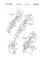
- FIG. 1is a simplified schematic view of the indwelling urethral catheter with incontinence control incorporating one embodiment of the invention, during installation in a penis;
- FIG. 2is a view similar to FIG. 1 with the collection bag and inflation arrangement removed;
- FIG. 3is a view similar to FIG. 2 showing the manner in which the incontinence device is magnetically actuated to permit drainage of fluid from the bladder;
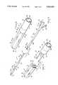
- FIG. 4is a disassembled perspective view of the indwelling urethral catheter with incontinence control prior to installation in the urethral passage and bladder;
- FIG. 5is an enlarged fragmentary perspective view thereof
- FIG. 6is a view similar to FIG. 5 in assembled condition
- FIG. 7is an enlarged fragmentary sectional view thereof corresponding to FIG. 5;
- FIG. 8is an enlarged fragmentary sectional view thereof corresponding to FIG. 6;
- FIG. 9is a sectional view taken on the line 9--9 of FIG. 8;
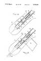
- FIG. 10is an enlarged fragmentary view thereof in operational position with the valve means in a valve closed position
- FIG. 11is a view similar to FIG. 10 showing the valve means magnetically actuated to an open position to permit fluid flow;
- FIGS. 12 and 13illustrate a further embodiment of the invention in valve closed and valve open positions corresponding to that shown in the embodiments of FIGS. 10 and 11.
- a catheter assembly incorporating one embodiment of the inventionis generally indicated by the reference number 10 in FIG. 1.
- the catheter assembly 10includes an incontinence portion 12 and an inflation/ drainage member 14 adapted to be detachably joined to the incontinence portion 12.
- the incontinence portion 12comprises an elongated tubular member 16 which can be formed of silicone.
- the tubular member 16has an outside tubular surface 18 and an interior fluid drainage passage 20.
- the drainage passage 20extends from an end portion 22 of the tubular member 16 to an opposite end portion 28 thereof.
- the end portion 22 of the tubular member 16is provided with oppositely disposed bladder drainage openings 24 and 26 that communicate with the drainage passage 20.
- An inflatable bladder balloon 30, preferably formed of siliconeis joined to the periphery of the tubular member 16 at a predetermined distance from the end portion 22.
- An inflatable urethra cuff 32 also formed of siliconeis joined to the periphery of the tubular member 16 at a predetermined distance from the bladder balloon 30.
- the bladder balloon 30 and the urethral cuff 32are initially deflated as shown in FIG. 4.
- Opposite end portions 34 and 36 of the bladder balloon 30are secured to the outer surface 18 of the tubular member 16 in leak-tight arrangement using a suitable known silicone adhesive.
- opposite end portions 38 and 40 of the urethral cuff 32are secured to the tubular surface 18 of the tubular member 16 in leaktight fashion.
- a pair of inflation lumen 42 and 44are formed on the interior of the tubular member 16.
- the inflation lumen 42for example, communicates with the bladder balloon 30, and the inflation lumen 44 communicates with the urethral cuff 32.
- a distal end portion 46 of the inflation lumen 42is provided with a spring biased ball valve 48 that is in a normally closed position against a valve seat 50.
- the inflation lumen 44 at a distal portion 52includes a spring biased ball valve 54 that is normally in a closed position against a valve seat 56.
- An incontinence valve 60is provided in the incontinence portion 12 a predetermined distance from the end portion 28 of the tubular member 16.
- the incontinence valve 60includes a ball member 64 normally biased against a valve seat portion 66 having a surface of conical form and a valve orifice 68.
- the ball member 64can be formed, for example of stainless steel with gold plating, plastic, silicone or borosilicate glass.
- Biasing means 70 for urging the ball member 64 to close the orifice 68include a biasing spring 72 and a magnetically actuatable member 74 in the form of a cylinder, secured to one end of the biasing spring 72.
- the biasing spring 70can be formed of stainless steel (MP35N), monel or any other suitable nonmagnetic spring material.
- a spring seat member 76is provided a predetermined distance from the valve seat 66 for retaining an opposite end of the biasing spring 72.
- the spring seat 76can be formed of stainless steel or plastic, for example.
- the incontinence valve 60which is in a normally closed position, is actuated to an open condition by an external manually movable magnet 77 (FIGS. 3, 11 and 13).
- the magnet 77can be formed of a rare earth magnet such as neodymium-iron-boron or samarium-cobalt.
- the magnetically actuatable member 74can also be formed of neodymium-ironboron or samarium-cobalt.
- the incontinence valve 60when normally closed as shown in FIG. 10, prevents fluid from the fluid drainage passage 20 from passing through the valve orifice 68, thus maintaining continence.
- the biasing spring 72 and the magnetically actuatable member 74are selected to provide a predetermined biasing force on the ball member 64 that is sufficient to maintain the ball member 64 in a closed position during activities associated with a relatively active individual. Thus there is little likelihood that the ball member 64 would inadvertently unseat from the valve seat 66 as a result of physical activity or movement of the user.
- the incontinence valve 60provides an automatic pressure relief safety feature wherein the relief pressure is a function of the spring force.
- the magnet 77When it is desired to actuate the incontinence valve 60 to an open condition, the magnet 77 is manually placed adjacent the penis 79 as shown in FIG. 11, thereby attracting (or repelling) the magnetically actuatable member 74 from the position of FIG. 10. Movement of the magnetically actuatable member 74 from its position of alignment with the ball 64 and the orifice 68 enables the ball 64 to unseat from the valve seat 66 and permit fluid to flow through the orifice in the manner shown in FIG. 11.
- the magnetically actuatable member 74 and the ball member 64are sized such that the ball cannot pass between the magnetically actuatable member 74 and the wall of the tubular member 16. Thus for all possible deflections of the magnetically actuatable member 74 the ball member 64 is always retained between the free end portion of the magnetically actuatable member 74 and the valve seat 66.
- the biasing spring 72 and the magnetically actuatable member 74urge the ball member 64 against the valve seat 66 into the normally closed position wherein the ball member 64 closes the orifice 68.
- the externally movable magnet 77is preferably of a size that is unobtrusive and can be stored in a pocket, such as for example, 1 inch ⁇ 3 inches ⁇ 3/16 inches thick. If desired, the externally movable magnet 77 can be sheathed in a bag or container that is nonmagnetic.
- the inflation/drainage member 14comprises a drainage duct member 78 having an interior duct passage 80 that extends from an end portion 82 (FIG. 4) to an opposite end portion 84.
- the drainage duct membercan be formed of silicone, polyvinyl chloride, or any other suitable known biocompatible thermoplastic.
- a pair of inflation lumen 86 and 88(FIGS. 5-8) corresponding to the inflation lumen 42 and 44 are formed on the inner surface of the duct passage 80.
- An engagement assembly 90formed of a suitable plastic or metal such as stainless steel, includes a cap portion 92 adapted to form a leak-tight seal around the end portion 82 of the drainage duct member 78.
- a pair of inflation needles 94 and 96having respective inflation openings 98 and 100, extend longitudinally from the cap portion 92.
- the inflation needles 94 and 96align with and form a continuation of the inflation lumen 86 and 88.
- Blunt ends 102 and 104are formed at the respective free ends of the inflation needles 94 and 96.
- a duct extension piece 106which can be formed of plastic or stainless steel, projects from the cap portion 92 intermediate the inflation needles 94 and 96.
- the duct extension 106defines a duct extension passage 107 that is a continuation of the duct passage 80 and is of complementary cross section with the drainage passage 20 at the distal end 28 of the tubular member 16.
- a branch member 110joins the end portion 84 of the drainage duct member 78 and includes a drainage extension 112 that communicates with the duct passage 80.
- the branch member 110also includes syringe receivers 114 and 116 that respectively communicate with the inflation lumen 86 and 88.
- the inflation/ drainage member 14is joined to the incontinence portion 12 by aligning the inflation needles 94 and 96 with the lumen portions 42 and 44 of the tubular member 12 as shown in FIG. 5.
- a free end portion of the duct extension 106will thus be received in the fluid passage 20 downstream from the incontinence valve 60 as the inflation needles 94 and 96 are received in the lumen portions 42 and 44 for engagement in the manner shown in FIGS. 6 and 8.
- the periphery of the tubular member 12is substantially identical to the periphery of the cap portion to provide a smooth continuous surface where the tubular member 12 and the engagement assembly 90 join.
- the inflation needles 94 and 96as they pass into the distal ends 46 and 52 of the lumen portions 42 and 44, unseat the respective balls 48 and 54 from their respective valve seats 50 and 56 for entry into the inflation lumens 42 and 44 of the tubular member 16 as shown in FIG. 8.
- a collection bag 118(FIG. 1) is connected to the drainage extension 112 and respective syringes 120 and 122 are positioned in the syringe receivers 114 and 116 with appropriate predetermined amounts of a suitable known inflation fluid.
- a suitable known lubricant(not shown) is applied to the tubular surface 18 of the tubular member 16.
- the tubular member 16is inserted into the urethra 128 to position the uninflated bladder balloon 30 in the bladder 130.
- the tubular member 16is sized such that the incontinence valve 60 substantially aligns with the penile meatus.
- Tubular members 16 of various different lengthscan be inventoried to ensure such alignment with the penile meatus.
- the syringes 120 and 122can be operated to force fluid through the respective lumen passages 86-42 and 88-44 to inflate the bladder balloon 30 and the urethral cuff 32 in the manner shown in FIG. 2.
- the syringes 120 and 122are removed and self-sealing valves 124 and 126 provided on the syringe receivers 114 and 116 ensure that the inflation volume of the bladder balloon 30 and the urethral cuff 32 is maintained.
- Bladder fluid 132(FIG. 4) is thus enabled to pass into the openings 24 and 26 for passage through the fluid drainage passage 20, into the duct extension passage 107 and through the duct passage 80 into the collection bag 118. There is no communication between the fluid passages 20, 107, 80 and the inflation lumens 42, 44 and 86, 88.
- bladder fluid 132can be continuously drained from the bladder 130 past the incontinence valve 60 into the collection bag 118, provided the external magnet 77 is maintained proximate the penis, in any suitable manner, such as for example, in a truss-like arrangement (not shown) which holds the magnet 77 proximate the penis. If continuous drainage is not desired but the collection bag 118 is to be used, the incontinence valve 60 is maintained in the normally closed position and operated using the magnet 77 in the manner previously described. The filled collection bag 118 can be emptied or replaced as needed.
- the inflation/drainage member 14is detached from the incontinence portion 12 in the manner shown in FIG. 2.
- the patientcan manually control bladder drainage by selectively opening the incontinence valve 60 using the magnet 77.
- the inflation needles 94 and 96are withdrawn from the lumen 42 and 44 and the spring biased ball valves 48 and 54 assume their normally closed positions. Inflation volume of the bladder balloon 30 and urethral cuff 32 is thus maintained.
- the patientmanually holds the magnet 77 adjacent the penis in the manner shown in FIG. 11.
- the magnet 77need not be accurately located since it has sufficient flux to open the valve 60 when placed alongside the penis near the penile meatus.
- a patientcan thus control and limit bladder discharge as he chooses.
- the incontinence portion 12 which permits such controlis entirely recessed in the penis and substantially undetectable.
- the penisis collapsed against the pubis, exposing the distal end of the incontinence portion 12.
- the tube member 16is cut just proximal to the valves 48 and 54 to enable the bladder balloon 30 and the urethral cuff 32 to deflate.
- the incontinence portion 12can then be removed.
- the catheter assembly 140which includes an incontinence portion 142, does not have a pressure relief feature and is structurally identical to the catheter assembly 10 except for the orientation of an incontinence valve 150 in the incontinence portion 142.
- the incontinence valve 150includes components that are identical to the incontinence valve 60. However the valve seat 66 and the ball member 64 are at a downstream flow portion of the tubular member 16.
- urethral indwelling catheter with incontinence controlthat provides the option of continuous bladder drainage as well as the option of user controlled bladder drainage. Either option can be obtained with just one installation of a catheter assembly in the urethra and bladder.
- valve means for controlling movement of fluid from the bladdercan be magnetically actuatable by a small, relatively innocuous magnet that is no larger than a small key case and can be easily carried around by the user.
- incontinence valvedoes not require manual manipulation of the penis to actuate the valve. Such manual manipulation can cause discomfort and may require manual dexterity. Use of the present magnetic device requires little manual dexterity, and does not require manipulation of the penis to actuate the incontinence valve and thus does not cause discomfort.
Landscapes
- Health & Medical Sciences (AREA)
- Urology & Nephrology (AREA)
- Cardiology (AREA)
- Oral & Maxillofacial Surgery (AREA)
- Transplantation (AREA)
- Engineering & Computer Science (AREA)
- Biomedical Technology (AREA)
- Heart & Thoracic Surgery (AREA)
- Vascular Medicine (AREA)
- Life Sciences & Earth Sciences (AREA)
- Animal Behavior & Ethology (AREA)
- General Health & Medical Sciences (AREA)
- Public Health (AREA)
- Veterinary Medicine (AREA)
- External Artificial Organs (AREA)
- Orthopedics, Nursing, And Contraception (AREA)
Abstract
Description
Claims (18)
Priority Applications (1)
| Application Number | Priority Date | Filing Date | Title |
|---|---|---|---|
| US07/608,605US5041092A (en) | 1989-08-29 | 1990-10-30 | Urethral indwelling catheter with magnetically controlled drainage valve and method |
Applications Claiming Priority (2)
| Application Number | Priority Date | Filing Date | Title |
|---|---|---|---|
| US40019489A | 1989-08-29 | 1989-08-29 | |
| US07/608,605US5041092A (en) | 1989-08-29 | 1990-10-30 | Urethral indwelling catheter with magnetically controlled drainage valve and method |
Related Parent Applications (1)
| Application Number | Title | Priority Date | Filing Date |
|---|---|---|---|
| US40019489AContinuation | 1989-08-29 | 1989-08-29 |
Publications (1)
| Publication Number | Publication Date |
|---|---|
| US5041092Atrue US5041092A (en) | 1991-08-20 |
Family
ID=27016943
Family Applications (1)
| Application Number | Title | Priority Date | Filing Date |
|---|---|---|---|
| US07/608,605Expired - LifetimeUS5041092A (en) | 1989-08-29 | 1990-10-30 | Urethral indwelling catheter with magnetically controlled drainage valve and method |
Country Status (1)
| Country | Link |
|---|---|
| US (1) | US5041092A (en) |
Cited By (135)
| Publication number | Priority date | Publication date | Assignee | Title |
|---|---|---|---|---|
| US5140999A (en)* | 1991-09-30 | 1992-08-25 | Primed International Corp. | Urinary incontinence valve device |
| US5167237A (en)* | 1991-07-09 | 1992-12-01 | Long Island Jewish Medical Center | Apparatus for monitoring detrusor pressure exerted by a bladder |
| US5352182A (en)* | 1992-05-27 | 1994-10-04 | Kalb Irvin M | Product and method to treat female incontinence |
| US5359995A (en)* | 1991-02-04 | 1994-11-01 | Sewell Jr Frank | Method of using an inflatable laparoscopic retractor |
| US5366506A (en)* | 1993-04-05 | 1994-11-22 | Davis Phillip J | Proximity intraurethral valve using permanent magnet check |
| US5379759A (en)* | 1991-02-04 | 1995-01-10 | Sewell, Jr.; Frank K. | Retractor for endoscopic surgery |
| US5380268A (en)* | 1993-06-07 | 1995-01-10 | Wheeler; Douglas E. | Body fluid flow control valve and method |
| US5437604A (en)* | 1993-12-23 | 1995-08-01 | Hk Medical Technologies, Incorporated | Nonsurgical intraurethral bladder control device |
| US5509888A (en)* | 1994-07-26 | 1996-04-23 | Conceptek Corporation | Controller valve device and method |
| US5618257A (en)* | 1995-08-16 | 1997-04-08 | Hk Medical Technologies Incorporated | Bladder control insertion apparatus and method |
| US5624374A (en)* | 1994-11-03 | 1997-04-29 | Von Iderstein; Irwin F. | Involuntary urine control apparatus, system and method |
| US5624395A (en)* | 1995-02-23 | 1997-04-29 | Cv Dynamics, Inc. | Urinary catheter having palpitatable valve and balloon and method for making same |
| WO1997046273A1 (en)* | 1996-06-05 | 1997-12-11 | Urocath Corporation | Indwelling magnetically-actuated urinary catheter, and method of its construction |
| US5701916A (en)* | 1995-08-16 | 1997-12-30 | Hk Medical Technologies Incorporated | Intraurethral bladder control device with retainer apparatus |
| US5749826A (en)* | 1996-11-06 | 1998-05-12 | Faulkner; James W. | Urinary incontinence control device |
| US5762599A (en)* | 1994-05-02 | 1998-06-09 | Influence Medical Technologies, Ltd. | Magnetically-coupled implantable medical devices |
| US5785641A (en)* | 1996-05-08 | 1998-07-28 | Urocath Corporation | Male indwelling urethral catheter sizing system and insertion method |
| US5785694A (en)* | 1995-12-01 | 1998-07-28 | Cohen; Kenneth L. | Internal urinary catheter |
| US5851218A (en)* | 1996-09-03 | 1998-12-22 | Lev; Shlomo | Annular catheter method of assembling and method of using the same |
| US5871016A (en)* | 1997-10-08 | 1999-02-16 | Hk Medical Technologies Incorporated | Bladder control device retainer and method |
| US5951566A (en)* | 1997-01-02 | 1999-09-14 | Lev; Shlomo | Annular catheter |
| JP2954997B2 (en) | 1989-08-29 | 1999-09-27 | ユーロカス コーポレイション | Urethral catheter |
| US5964732A (en)* | 1997-02-07 | 1999-10-12 | Abbeymoor Medical, Inc. | Urethral apparatus with position indicator and methods of use thereof |
| WO1999051293A1 (en)* | 1998-04-05 | 1999-10-14 | Johannes Dohmen | Bladder-neck indwelling catheter with an opening and closing device which can be controlled in a contactless manner to empty urine from the bladder |
| US5971967A (en)* | 1997-08-19 | 1999-10-26 | Abbeymoor Medical, Inc. | Urethral device with anchoring system |
| US5989179A (en)* | 1997-07-07 | 1999-11-23 | Hk Medical Technologies Incorporated | Bladder control device housing and method |
| US5996585A (en)* | 1997-08-21 | 1999-12-07 | Hk Medical Technologies Incorporated | Nonsurgical intraurethral bladder control device retainer |
| US6063119A (en)* | 1996-08-13 | 2000-05-16 | Galt Laboratories, Inc. | Device for maintaining urinary continence |
| US6066088A (en)* | 1998-07-13 | 2000-05-23 | Phillip Davis Inventions, Inc. | Intraurethral magnetic valve |
| US6105580A (en)* | 1994-11-03 | 2000-08-22 | Uroscientific, Incorporated | Urine control device |
| US6162201A (en)* | 1995-12-01 | 2000-12-19 | Cohen; Kenneth L. | Internal urinary catheter |
| US6183413B1 (en) | 1998-12-09 | 2001-02-06 | Hk Medical Technologies Incorporated | Valve for bladder control device |
| US6238368B1 (en)* | 1994-07-13 | 2001-05-29 | Marian Devonec | Therapeutic device for the selective cytoreduction treatment of an obstruction |
| WO2001056629A3 (en)* | 2000-02-03 | 2002-04-25 | Scimed Life Systems Inc | Prostatic stent facilitating drainage |
| USRE37704E1 (en) | 1990-03-22 | 2002-05-14 | Argomed Ltd. | Thermal treatment apparatus |
| US6395021B1 (en) | 1997-02-26 | 2002-05-28 | Applied Medical Resources Corporation | Ureteral stent system apparatus and method |
| US20020107540A1 (en)* | 2001-01-23 | 2002-08-08 | Whalen Mark J. | Endourethral device & method |
| US6443887B1 (en) | 2000-12-27 | 2002-09-03 | American Medical Systems Inc. | Switch based spontaneous inflation inhibitor in a pump for an inflation prosthesis |
| WO2002094134A1 (en)* | 2001-05-22 | 2002-11-28 | Scimed Life Systems, Inc. | Draining bodily fluids with a stent |
| US6494855B2 (en) | 2001-05-16 | 2002-12-17 | Scimed Life Systems, Inc. | Draining bodily fluid |
| US6494879B2 (en) | 1998-10-15 | 2002-12-17 | Scimed Life Systems, Inc. | Treating urinary retention |
| US20030040671A1 (en)* | 1996-06-17 | 2003-02-27 | Somogyi Christopher P. | Medical tube for insertion and detection within the body of a patient |
| US6527702B2 (en) | 2000-02-01 | 2003-03-04 | Abbeymoor Medical, Inc. | Urinary flow control device and method |
| US6533719B2 (en) | 2000-12-27 | 2003-03-18 | Ams Research Corporation | Diaphragm based spontaneous inflation inhibitor in a pump for an inflatable prosthesis |
| US6547785B1 (en)* | 2001-10-23 | 2003-04-15 | Biosense Webster, Inc. | Cryoablation catheter for long lesion ablations |
| US20030078467A1 (en)* | 2001-10-18 | 2003-04-24 | Whalen Mark J. | Endourethral device & method |
| US6582472B2 (en) | 1997-02-26 | 2003-06-24 | Applied Medical Resources Corporation | Kinetic stent |
| US6635058B2 (en) | 1992-11-13 | 2003-10-21 | Ams Research Corporation | Bone anchor |
| US20030208183A1 (en)* | 2000-08-07 | 2003-11-06 | Whalen Mark J. | Endourethral device & method |
| US6663642B2 (en) | 1992-11-13 | 2003-12-16 | Ams Research Corporation | System for bone screw insertion |
| US6673051B2 (en)* | 2001-04-02 | 2004-01-06 | Hook Research Foundation | Magnetic valve bladder cycler drainage system and use method with urinary catheters |
| US6676593B2 (en) | 1999-04-30 | 2004-01-13 | Hk Medical Technologies, Inc. | Intraurethral device and method |
| US6685745B2 (en) | 2001-05-15 | 2004-02-03 | Scimed Life Systems, Inc. | Delivering an agent to a patient's body |
| US6716252B2 (en) | 2000-06-30 | 2004-04-06 | Wit Ip Corporation | Prostatic stent with localized tissue engaging anchoring means and methods for inhibiting obstruction of the prostatic urethra |
| US6723042B2 (en) | 2000-12-27 | 2004-04-20 | Ams Research Corporation | Penile pump with side release mechanism |
| US6730017B2 (en) | 2000-12-27 | 2004-05-04 | Ams Research Corporation | Pressure based spontaneous inflation inhibitor with penile pump improvements |
| US20040138523A1 (en)* | 2002-12-02 | 2004-07-15 | Ams Research Corporation | Implantable pump |
| US20040172009A1 (en)* | 2003-02-27 | 2004-09-02 | Marisi Margaret Grahn | Urinary catheter with check valve |
| US6790223B2 (en) | 2001-09-21 | 2004-09-14 | Scimed Life Systems, Inc. | Delivering a uretheral stent |
| US20040193283A1 (en)* | 2003-03-26 | 2004-09-30 | Scimed Life Systems, Inc. | Longitudinally expanding medical device |
| US20040193093A1 (en)* | 2003-03-25 | 2004-09-30 | Desmond, Joseph P. | Retaining stent |
| US20040199246A1 (en)* | 2003-04-02 | 2004-10-07 | Scimed Life Systems, Inc. | Expandable stent |
| US6849063B1 (en) | 1994-03-11 | 2005-02-01 | Wit Ip Corporation | Thermal treatment apparatus |
| US20050043581A1 (en)* | 2003-04-25 | 2005-02-24 | Ling Jeremy J. | Penile prosthesis with improved tubing junction |
| US6893430B2 (en) | 1998-02-04 | 2005-05-17 | Wit Ip Corporation | Urethral catheter and guide |
| US20050222593A1 (en)* | 2004-03-19 | 2005-10-06 | Medical Components, Inc | Magnet cuff for vascular catheters and bloodlines |
| US20050283235A1 (en)* | 2002-04-26 | 2005-12-22 | Torax Medical, Inc. | Methods and apparatus for treating body tissue sphincters and the like |
| US20060009674A1 (en)* | 2000-08-08 | 2006-01-12 | Ev & M | Active tissue augmentation materials and method |
| EP1383557A4 (en)* | 2001-04-02 | 2006-04-12 | Hook Res Foundation | Conformable balloonless catheter |
| US7048698B2 (en) | 2001-06-22 | 2006-05-23 | Abbeymoor Medical, Inc. | Urethral profiling device and methodology |
| US7112226B2 (en) | 2002-10-22 | 2006-09-26 | Boston Scientific Scimed, Inc. | Male urethral stent device |
| US20060247666A1 (en)* | 2005-04-28 | 2006-11-02 | Ams Research Corporation | Protective enclosure for medical device components |
| US20070049907A1 (en)* | 2005-08-12 | 2007-03-01 | Fischer Frank J Jr | Drainage catheter with extended inflation lumen |
| US20070276342A1 (en)* | 2006-03-28 | 2007-11-29 | Bryant Lin | Devices and related methods for treating incontinence |
| US7390324B2 (en) | 1999-12-01 | 2008-06-24 | Abbeymoor Medical, Inc. | Magnetic retrieval device and method of use |
| US20080208010A1 (en)* | 2007-02-22 | 2008-08-28 | Searete Llc, A Limited Liability Corporation Of The State Of Delaware | Coded-sequence activation of surgical implants |
| US20080281284A1 (en)* | 2007-05-08 | 2008-11-13 | Garfield Michael H | Fluid collection system |
| US7613491B2 (en) | 2002-05-22 | 2009-11-03 | Dexcom, Inc. | Silicone based membranes for use in implantable glucose sensors |
| US7615007B2 (en) | 2006-10-04 | 2009-11-10 | Dexcom, Inc. | Analyte sensor |
| US7640048B2 (en) | 2004-07-13 | 2009-12-29 | Dexcom, Inc. | Analyte sensor |
| US7651529B2 (en) | 2003-05-09 | 2010-01-26 | Boston Scientific Scimed, Inc. | Stricture retractor |
| EP1944055A4 (en)* | 2005-09-28 | 2010-07-28 | Martinez Ignacio Rada | Valvate vesical catheter |
| US7783333B2 (en) | 2004-07-13 | 2010-08-24 | Dexcom, Inc. | Transcutaneous medical device with variable stiffness |
| US20100262239A1 (en)* | 2009-04-14 | 2010-10-14 | Searete Llc, A Limited Liability Corporation Of The State Delaware | Adjustable orthopedic implant and method for treating an orthopedic condition in a subject |
| US7885697B2 (en) | 2004-07-13 | 2011-02-08 | Dexcom, Inc. | Transcutaneous analyte sensor |
| US7946975B2 (en) | 2005-04-08 | 2011-05-24 | Ams Research Corporation | Fluid reservoir for penile implant devices |
| US8025651B1 (en) | 2009-03-17 | 2011-09-27 | John Braun | Anti-backflow urinary device |
| US8109870B2 (en) | 2006-11-10 | 2012-02-07 | Ams Research Corporation | Inflatable penile prosthesis bypass valve noise reduction |
| US20120053570A1 (en)* | 2009-04-20 | 2012-03-01 | Cheiron Japan Co. | Urination control device |
| US8275438B2 (en) | 2006-10-04 | 2012-09-25 | Dexcom, Inc. | Analyte sensor |
| US8277426B2 (en) | 2009-09-30 | 2012-10-02 | Wilcox Heather J | Male urinary incontinence device |
| US8287453B2 (en) | 2003-12-05 | 2012-10-16 | Dexcom, Inc. | Analyte sensor |
| US8298142B2 (en) | 2006-10-04 | 2012-10-30 | Dexcom, Inc. | Analyte sensor |
| US8364229B2 (en) | 2003-07-25 | 2013-01-29 | Dexcom, Inc. | Analyte sensors having a signal-to-noise ratio substantially unaffected by non-constant noise |
| US8364231B2 (en) | 2006-10-04 | 2013-01-29 | Dexcom, Inc. | Analyte sensor |
| US8364230B2 (en) | 2006-10-04 | 2013-01-29 | Dexcom, Inc. | Analyte sensor |
| US8396528B2 (en) | 2008-03-25 | 2013-03-12 | Dexcom, Inc. | Analyte sensor |
| US8425417B2 (en) | 2003-12-05 | 2013-04-23 | Dexcom, Inc. | Integrated device for continuous in vivo analyte detection and simultaneous control of an infusion device |
| US8425416B2 (en) | 2006-10-04 | 2013-04-23 | Dexcom, Inc. | Analyte sensor |
| US8447376B2 (en) | 2006-10-04 | 2013-05-21 | Dexcom, Inc. | Analyte sensor |
| US8449464B2 (en) | 2006-10-04 | 2013-05-28 | Dexcom, Inc. | Analyte sensor |
| US8478377B2 (en) | 2006-10-04 | 2013-07-02 | Dexcom, Inc. | Analyte sensor |
| US8562558B2 (en) | 2007-06-08 | 2013-10-22 | Dexcom, Inc. | Integrated medicament delivery device for use with continuous analyte sensor |
| US8562528B2 (en) | 2006-10-04 | 2013-10-22 | Dexcom, Inc. | Analyte sensor |
| US8626257B2 (en) | 2003-08-01 | 2014-01-07 | Dexcom, Inc. | Analyte sensor |
| US8886273B2 (en) | 2003-08-01 | 2014-11-11 | Dexcom, Inc. | Analyte sensor |
| US9763762B2 (en) | 2013-09-25 | 2017-09-19 | Medtronic, Inc. | Implantable urinary tract valve |
| US9763609B2 (en) | 2003-07-25 | 2017-09-19 | Dexcom, Inc. | Analyte sensors having a signal-to-noise ratio substantially unaffected by non-constant noise |
| US9775698B2 (en) | 2015-01-23 | 2017-10-03 | Spinal Singularity, Inc. | Urinary prosthesis systems |
| US9986942B2 (en) | 2004-07-13 | 2018-06-05 | Dexcom, Inc. | Analyte sensor |
| US10010392B1 (en) | 2017-09-06 | 2018-07-03 | Stanislaw L Zukowski | Indwelling valve actuated urinary catheter |
| US10327880B2 (en) | 2000-04-14 | 2019-06-25 | Attenuex Technologies, Inc. | Attenuation device for use in an anatomical structure |
| US10383510B2 (en) | 2000-04-14 | 2019-08-20 | Solace Therapeutics, Inc. | Implant with high vapor pressure medium |
| US10531894B2 (en) | 2012-08-10 | 2020-01-14 | Solace Therapeutics, Inc. | Methods and systems for performing a medical procedure |
| US10610137B2 (en) | 2005-03-10 | 2020-04-07 | Dexcom, Inc. | System and methods for processing analyte sensor data for sensor calibration |
| US10675435B2 (en) | 2015-04-01 | 2020-06-09 | Spinal Singularity, Inc. | Extended-use valved urinary catheter |
| US10751506B2 (en) | 2015-04-01 | 2020-08-25 | Spinal Singularity, Inc. | Catheters and catheter mating devices and systems |
| US10780243B2 (en) | 2013-01-25 | 2020-09-22 | Javier G. Reyes | Method and apparatus for treatment of human urinary incontinence |
| US10791928B2 (en) | 2007-05-18 | 2020-10-06 | Dexcom, Inc. | Analyte sensors having a signal-to-noise ratio substantially unaffected by non-constant noise |
| US10813577B2 (en) | 2005-06-21 | 2020-10-27 | Dexcom, Inc. | Analyte sensor |
| US10835672B2 (en) | 2004-02-26 | 2020-11-17 | Dexcom, Inc. | Integrated insulin delivery system with continuous glucose sensor |
| US10966609B2 (en) | 2004-02-26 | 2021-04-06 | Dexcom, Inc. | Integrated medicament delivery device for use with continuous analyte sensor |
| US10980461B2 (en) | 2008-11-07 | 2021-04-20 | Dexcom, Inc. | Advanced analyte sensor calibration and error detection |
| US11000215B1 (en) | 2003-12-05 | 2021-05-11 | Dexcom, Inc. | Analyte sensor |
| US11065093B2 (en) | 2015-01-23 | 2021-07-20 | Spinal Singularity, Inc. | Catheter mating devices |
| US11197981B2 (en) | 2019-02-07 | 2021-12-14 | Solace Therapeutics, Inc. | Pressure attenuation device |
| US11246990B2 (en) | 2004-02-26 | 2022-02-15 | Dexcom, Inc. | Integrated delivery device for continuous glucose sensor |
| US11331022B2 (en) | 2017-10-24 | 2022-05-17 | Dexcom, Inc. | Pre-connected analyte sensors |
| US11350862B2 (en) | 2017-10-24 | 2022-06-07 | Dexcom, Inc. | Pre-connected analyte sensors |
| US11399745B2 (en) | 2006-10-04 | 2022-08-02 | Dexcom, Inc. | Dual electrode system for a continuous analyte sensor |
| US11510765B2 (en) | 2015-01-23 | 2022-11-29 | Spinal Singularity, Inc. | Extended-use catheters |
| US11628271B2 (en) | 2019-06-10 | 2023-04-18 | Spinal Singularity, Inc. | Urinary catheter |
| US11633133B2 (en) | 2003-12-05 | 2023-04-25 | Dexcom, Inc. | Dual electrode system for a continuous analyte sensor |
| US11752302B1 (en) | 2022-11-28 | 2023-09-12 | Stanislaw Zukowski | Indwelling valve actuated urinary catheter |
| US11865270B2 (en) | 2020-01-16 | 2024-01-09 | Starling Medical, Inc. | Bodily fluid management system |
Citations (10)
| Publication number | Priority date | Publication date | Assignee | Title |
|---|---|---|---|---|
| US3354898A (en)* | 1966-05-02 | 1967-11-28 | Standard Screw | Crankcase ventilating valve having rotatable metering plunger |
| US3419008A (en)* | 1966-02-24 | 1968-12-31 | Paul J. Plishner | Magnetically actuated valve clamp for urethra control |
| US3503400A (en)* | 1967-07-12 | 1970-03-31 | Sven M Osthagen | Urethral valve |
| GB1194358A (en)* | 1967-11-22 | 1970-06-10 | Dana Christopher Mears | Fluid Flow Control Valve. |
| US3642004A (en)* | 1970-01-05 | 1972-02-15 | Life Support Equipment Corp | Urethral valve |
| US3731670A (en)* | 1971-05-03 | 1973-05-08 | David Roy Pressman | Corporeal fluid control using bistable magnetic duct valve |
| US3812841A (en)* | 1972-08-21 | 1974-05-28 | L Isaacson | Urethra magnetic valve structure |
| DE2537506A1 (en)* | 1975-08-22 | 1977-03-03 | Hennig Gerhard | Bladder outlet valve for incontinent people - has magnet cone embedded in magnet ring seat with powerful external opening magnet |
| US4850963A (en)* | 1986-06-11 | 1989-07-25 | Utah Bioresearch, Inc. | Apparatus and methods for achieving urinary continence |
| US4932938A (en)* | 1989-05-05 | 1990-06-12 | Medical Engineering Corporation | Urethral indwelling catheter with incontinence control |
- 1990
- 1990-10-30USUS07/608,605patent/US5041092A/ennot_activeExpired - Lifetime
Patent Citations (10)
| Publication number | Priority date | Publication date | Assignee | Title |
|---|---|---|---|---|
| US3419008A (en)* | 1966-02-24 | 1968-12-31 | Paul J. Plishner | Magnetically actuated valve clamp for urethra control |
| US3354898A (en)* | 1966-05-02 | 1967-11-28 | Standard Screw | Crankcase ventilating valve having rotatable metering plunger |
| US3503400A (en)* | 1967-07-12 | 1970-03-31 | Sven M Osthagen | Urethral valve |
| GB1194358A (en)* | 1967-11-22 | 1970-06-10 | Dana Christopher Mears | Fluid Flow Control Valve. |
| US3642004A (en)* | 1970-01-05 | 1972-02-15 | Life Support Equipment Corp | Urethral valve |
| US3731670A (en)* | 1971-05-03 | 1973-05-08 | David Roy Pressman | Corporeal fluid control using bistable magnetic duct valve |
| US3812841A (en)* | 1972-08-21 | 1974-05-28 | L Isaacson | Urethra magnetic valve structure |
| DE2537506A1 (en)* | 1975-08-22 | 1977-03-03 | Hennig Gerhard | Bladder outlet valve for incontinent people - has magnet cone embedded in magnet ring seat with powerful external opening magnet |
| US4850963A (en)* | 1986-06-11 | 1989-07-25 | Utah Bioresearch, Inc. | Apparatus and methods for achieving urinary continence |
| US4932938A (en)* | 1989-05-05 | 1990-06-12 | Medical Engineering Corporation | Urethral indwelling catheter with incontinence control |
Cited By (304)
| Publication number | Priority date | Publication date | Assignee | Title |
|---|---|---|---|---|
| JP2954997B2 (en) | 1989-08-29 | 1999-09-27 | ユーロカス コーポレイション | Urethral catheter |
| USRE37704E1 (en) | 1990-03-22 | 2002-05-14 | Argomed Ltd. | Thermal treatment apparatus |
| US5379759A (en)* | 1991-02-04 | 1995-01-10 | Sewell, Jr.; Frank K. | Retractor for endoscopic surgery |
| US5359995A (en)* | 1991-02-04 | 1994-11-01 | Sewell Jr Frank | Method of using an inflatable laparoscopic retractor |
| US5167237A (en)* | 1991-07-09 | 1992-12-01 | Long Island Jewish Medical Center | Apparatus for monitoring detrusor pressure exerted by a bladder |
| US5140999A (en)* | 1991-09-30 | 1992-08-25 | Primed International Corp. | Urinary incontinence valve device |
| US5352182A (en)* | 1992-05-27 | 1994-10-04 | Kalb Irvin M | Product and method to treat female incontinence |
| US6663642B2 (en) | 1992-11-13 | 2003-12-16 | Ams Research Corporation | System for bone screw insertion |
| US6635058B2 (en) | 1992-11-13 | 2003-10-21 | Ams Research Corporation | Bone anchor |
| US5366506A (en)* | 1993-04-05 | 1994-11-22 | Davis Phillip J | Proximity intraurethral valve using permanent magnet check |
| US5380268A (en)* | 1993-06-07 | 1995-01-10 | Wheeler; Douglas E. | Body fluid flow control valve and method |
| EP1350483A3 (en)* | 1993-12-23 | 2004-01-14 | Feelsure Health Corporation | Nonsurgical intraurethral bladder control device |
| US6237623B1 (en) | 1993-12-23 | 2001-05-29 | Hk Medical Technologies Incorporated | Nonsurgical intraurethral bladder control device |
| US5437604A (en)* | 1993-12-23 | 1995-08-01 | Hk Medical Technologies, Incorporated | Nonsurgical intraurethral bladder control device |
| US5722932A (en)* | 1993-12-23 | 1998-03-03 | Hk Medical Technologies Incorporated | Nonsurgical intraurethral bladder control device |
| US5512032A (en)* | 1993-12-23 | 1996-04-30 | Hk Medical Technologies, Inc. | Nonsurgical intraurethral bladder control device |
| US6849063B1 (en) | 1994-03-11 | 2005-02-01 | Wit Ip Corporation | Thermal treatment apparatus |
| US5762599A (en)* | 1994-05-02 | 1998-06-09 | Influence Medical Technologies, Ltd. | Magnetically-coupled implantable medical devices |
| US20050113748A1 (en)* | 1994-07-13 | 2005-05-26 | Marian Devonec | Therapeutic device for the selective cytoreduction treatment of an obstruction in a natural lumen or passage of the human or animal body |
| US8211085B2 (en) | 1994-07-13 | 2012-07-03 | Marian Devonec | Therapeutic device for the selective cytoreduction treatment of an obstruction in a natural lumen or passage of the human or animal body |
| US20010041883A1 (en)* | 1994-07-13 | 2001-11-15 | Marian Devonec | Therapeutic device for the selective cytoreduction treatment of an obstruction in a natural lumen or passage of the human or animal body |
| US6238368B1 (en)* | 1994-07-13 | 2001-05-29 | Marian Devonec | Therapeutic device for the selective cytoreduction treatment of an obstruction |
| US6949083B2 (en) | 1994-07-13 | 2005-09-27 | Marian Devonec | Therapeutic device for the selective cytoreduction treatment of an obstruction in a natural lumen or passage of the human or animal body |
| US5509888A (en)* | 1994-07-26 | 1996-04-23 | Conceptek Corporation | Controller valve device and method |
| US6027442A (en)* | 1994-11-03 | 2000-02-22 | Uroscientific, Inc. | Urethra control device |
| US5624374A (en)* | 1994-11-03 | 1997-04-29 | Von Iderstein; Irwin F. | Involuntary urine control apparatus, system and method |
| US6105580A (en)* | 1994-11-03 | 2000-08-22 | Uroscientific, Incorporated | Urine control device |
| US5707357A (en)* | 1995-02-23 | 1998-01-13 | C V Dynamics, Inc. | Balloon catheter having palpitatable discharge valve and retention collar |
| US5624395A (en)* | 1995-02-23 | 1997-04-29 | Cv Dynamics, Inc. | Urinary catheter having palpitatable valve and balloon and method for making same |
| US5701916A (en)* | 1995-08-16 | 1997-12-30 | Hk Medical Technologies Incorporated | Intraurethral bladder control device with retainer apparatus |
| US6193646B1 (en) | 1995-08-16 | 2001-02-27 | Hk Medical Technologies Incorporated | Intraurethral bladder control device with retainer apparatus |
| US5846180A (en)* | 1995-08-16 | 1998-12-08 | Hk Medical Technologies Incorporated | Bladder control insertion apparatus and method |
| US5887592A (en)* | 1995-08-16 | 1999-03-30 | Hk Medical Technologies Incorporated | Intraurethral bladder control device with retainer apparatus |
| US6203488B1 (en) | 1995-08-16 | 2001-03-20 | Hk Medical Technologies Incorporated | Bladder control insertion apparatus and method |
| US5618257A (en)* | 1995-08-16 | 1997-04-08 | Hk Medical Technologies Incorporated | Bladder control insertion apparatus and method |
| US6162201A (en)* | 1995-12-01 | 2000-12-19 | Cohen; Kenneth L. | Internal urinary catheter |
| US5785694A (en)* | 1995-12-01 | 1998-07-28 | Cohen; Kenneth L. | Internal urinary catheter |
| US5785641A (en)* | 1996-05-08 | 1998-07-28 | Urocath Corporation | Male indwelling urethral catheter sizing system and insertion method |
| WO1997046273A1 (en)* | 1996-06-05 | 1997-12-11 | Urocath Corporation | Indwelling magnetically-actuated urinary catheter, and method of its construction |
| US5713877A (en)* | 1996-06-05 | 1998-02-03 | Urocath Corporation | Indwelling magnetically-actuated urinary catheter, and method of its construction |
| AU714563B2 (en)* | 1996-06-05 | 2000-01-06 | Urocath Corporation | Indwelling magnetically-actuated urinary catheter, and method of its construction |
| US20030040671A1 (en)* | 1996-06-17 | 2003-02-27 | Somogyi Christopher P. | Medical tube for insertion and detection within the body of a patient |
| US6063119A (en)* | 1996-08-13 | 2000-05-16 | Galt Laboratories, Inc. | Device for maintaining urinary continence |
| US5851218A (en)* | 1996-09-03 | 1998-12-22 | Lev; Shlomo | Annular catheter method of assembling and method of using the same |
| US5749826A (en)* | 1996-11-06 | 1998-05-12 | Faulkner; James W. | Urinary incontinence control device |
| US5951566A (en)* | 1997-01-02 | 1999-09-14 | Lev; Shlomo | Annular catheter |
| US6258060B1 (en) | 1997-02-07 | 2001-07-10 | Abbeymoon Medical, Inc. | Urethral apparatus with position indicator and methods of use thereof |
| US5964732A (en)* | 1997-02-07 | 1999-10-12 | Abbeymoor Medical, Inc. | Urethral apparatus with position indicator and methods of use thereof |
| US6582472B2 (en) | 1997-02-26 | 2003-06-24 | Applied Medical Resources Corporation | Kinetic stent |
| US6395021B1 (en) | 1997-02-26 | 2002-05-28 | Applied Medical Resources Corporation | Ureteral stent system apparatus and method |
| US5989179A (en)* | 1997-07-07 | 1999-11-23 | Hk Medical Technologies Incorporated | Bladder control device housing and method |
| US6221060B1 (en) | 1997-08-19 | 2001-04-24 | Abbeymoor Medical, Inc. | Urethral device with anchoring system |
| US5971967A (en)* | 1997-08-19 | 1999-10-26 | Abbeymoor Medical, Inc. | Urethral device with anchoring system |
| EP1015061A4 (en)* | 1997-08-19 | 2000-09-13 | Abbeymoor Medical Inc | Urethral device with anchoring system |
| US5996585A (en)* | 1997-08-21 | 1999-12-07 | Hk Medical Technologies Incorporated | Nonsurgical intraurethral bladder control device retainer |
| US5871016A (en)* | 1997-10-08 | 1999-02-16 | Hk Medical Technologies Incorporated | Bladder control device retainer and method |
| US6070588A (en)* | 1997-10-08 | 2000-06-06 | Hk Medical Technologies Incorporated | Bladder control device retainer and method |
| US6893430B2 (en) | 1998-02-04 | 2005-05-17 | Wit Ip Corporation | Urethral catheter and guide |
| WO1999051293A1 (en)* | 1998-04-05 | 1999-10-14 | Johannes Dohmen | Bladder-neck indwelling catheter with an opening and closing device which can be controlled in a contactless manner to empty urine from the bladder |
| US6066088A (en)* | 1998-07-13 | 2000-05-23 | Phillip Davis Inventions, Inc. | Intraurethral magnetic valve |
| US7547291B2 (en) | 1998-10-15 | 2009-06-16 | Boston Scientific Scimed, Inc. | Treating urinary retention |
| US6494879B2 (en) | 1998-10-15 | 2002-12-17 | Scimed Life Systems, Inc. | Treating urinary retention |
| US8007458B2 (en) | 1998-10-15 | 2011-08-30 | Boston Scientific Scimed, Inc. | Treating urinary retention |
| US6835183B2 (en) | 1998-10-15 | 2004-12-28 | Scimed Life Systems Inc. | Treating urinary retention |
| US20060241338A1 (en)* | 1998-12-09 | 2006-10-26 | Feelsure Health Corporation | Valve for bladder control device |
| US20040059185A1 (en)* | 1998-12-09 | 2004-03-25 | Hk Medical Technologies, Inc. | Valve for bladder control device |
| US6652448B2 (en) | 1998-12-09 | 2003-11-25 | Hk Medical Technologies, Inc. | Valve for bladder control device |
| US6926665B2 (en) | 1998-12-09 | 2005-08-09 | Feelsure Health Corporation | Valve for bladder control device |
| US6183413B1 (en) | 1998-12-09 | 2001-02-06 | Hk Medical Technologies Incorporated | Valve for bladder control device |
| US7087009B2 (en) | 1998-12-09 | 2006-08-08 | Feelsure Health Corporation | Valve for bladder control device |
| US20050245786A1 (en)* | 1998-12-09 | 2005-11-03 | Valery Migachyov | Valve for bladder control device |
| US6676593B2 (en) | 1999-04-30 | 2004-01-13 | Hk Medical Technologies, Inc. | Intraurethral device and method |
| US7241259B2 (en) | 1999-04-30 | 2007-07-10 | Feelsure Health Corporation | Intraurethral device and method |
| US20040097786A1 (en)* | 1999-04-30 | 2004-05-20 | Hk Medical Technologies Incorporated | Intraurethral device and method |
| US7390324B2 (en) | 1999-12-01 | 2008-06-24 | Abbeymoor Medical, Inc. | Magnetic retrieval device and method of use |
| US7001327B2 (en) | 2000-02-01 | 2006-02-21 | Abbeymoor Medical, Inc. | Urinary flow control device and method |
| US6527702B2 (en) | 2000-02-01 | 2003-03-04 | Abbeymoor Medical, Inc. | Urinary flow control device and method |
| US7044980B2 (en) | 2000-02-03 | 2006-05-16 | Boston Scientific Scimed, Inc. | Facilitating drainage |
| AU783830B2 (en)* | 2000-02-03 | 2005-12-08 | Boston Scientific Limited | Facilitating drainage |
| AU783830C (en)* | 2000-02-03 | 2007-07-26 | Boston Scientific Limited | Facilitating drainage |
| US20060206213A1 (en)* | 2000-02-03 | 2006-09-14 | Boston Scientific Scimed, Inc. | Facilitating drainage |
| WO2001056629A3 (en)* | 2000-02-03 | 2002-04-25 | Scimed Life Systems Inc | Prostatic stent facilitating drainage |
| US10383510B2 (en) | 2000-04-14 | 2019-08-20 | Solace Therapeutics, Inc. | Implant with high vapor pressure medium |
| US10327880B2 (en) | 2000-04-14 | 2019-06-25 | Attenuex Technologies, Inc. | Attenuation device for use in an anatomical structure |
| US6716252B2 (en) | 2000-06-30 | 2004-04-06 | Wit Ip Corporation | Prostatic stent with localized tissue engaging anchoring means and methods for inhibiting obstruction of the prostatic urethra |
| US20030208183A1 (en)* | 2000-08-07 | 2003-11-06 | Whalen Mark J. | Endourethral device & method |
| US7141038B2 (en) | 2000-08-07 | 2006-11-28 | Abbeymoor Medical, Inc. | Endourethral device and method |
| US7326172B2 (en) | 2000-08-08 | 2008-02-05 | Torax Medical, Inc. | Active tissue augmentation materials and method |
| US20060009674A1 (en)* | 2000-08-08 | 2006-01-12 | Ev & M | Active tissue augmentation materials and method |
| US8276591B2 (en) | 2000-12-27 | 2012-10-02 | Ams Research Corporation | Diaphragm based spontaneous inflation inhibitor in a pump for an inflatable prosthesis |
| US6533719B2 (en) | 2000-12-27 | 2003-03-18 | Ams Research Corporation | Diaphragm based spontaneous inflation inhibitor in a pump for an inflatable prosthesis |
| US7438682B2 (en) | 2000-12-27 | 2008-10-21 | Ams Research Corporation | Pressure based spontaneous inflation inhibitor with penile pump improvements |
| US6935847B2 (en) | 2000-12-27 | 2005-08-30 | Ams Research Corporation | Spontaneous inflation inhibitor for inflatable prosthesis |
| US20040220448A1 (en)* | 2000-12-27 | 2004-11-04 | Henkel Gregory J | Pressure based spontaneous inflation inhibitor with penile pump improvements |
| US7350538B2 (en) | 2000-12-27 | 2008-04-01 | Ams Research Corporation | Method of preventing inadvertent inflation of an inflatable prosthesis |
| US20030065249A1 (en)* | 2000-12-27 | 2003-04-03 | Kuyava Charles C. | Diaphragm based spontaneous inflation inhibitor in a pump for an inflatable prosthesis |
| US6443887B1 (en) | 2000-12-27 | 2002-09-03 | American Medical Systems Inc. | Switch based spontaneous inflation inhibitor in a pump for an inflation prosthesis |
| US20050250981A1 (en)* | 2000-12-27 | 2005-11-10 | Kuyava Charles C | Method of preventing inadvertent inflation of an inflatable prosthesis |
| US6730017B2 (en) | 2000-12-27 | 2004-05-04 | Ams Research Corporation | Pressure based spontaneous inflation inhibitor with penile pump improvements |
| US6723042B2 (en) | 2000-12-27 | 2004-04-20 | Ams Research Corporation | Penile pump with side release mechanism |
| US7108655B2 (en) | 2001-01-23 | 2006-09-19 | Abbeymoor Medical, Inc. | Endourethral device and method |
| US20020107540A1 (en)* | 2001-01-23 | 2002-08-08 | Whalen Mark J. | Endourethral device & method |
| US6673051B2 (en)* | 2001-04-02 | 2004-01-06 | Hook Research Foundation | Magnetic valve bladder cycler drainage system and use method with urinary catheters |
| EP1383557A4 (en)* | 2001-04-02 | 2006-04-12 | Hook Res Foundation | Conformable balloonless catheter |
| US20040127996A1 (en)* | 2001-05-15 | 2004-07-01 | Reever Kenneth P. | Delivering an agent to a patient's body |
| US6685745B2 (en) | 2001-05-15 | 2004-02-03 | Scimed Life Systems, Inc. | Delivering an agent to a patient's body |
| US8034119B2 (en) | 2001-05-15 | 2011-10-11 | Boston Scientific Scimed, Inc. | Delivering an agent to a patient's body |
| US20090164025A1 (en)* | 2001-05-15 | 2009-06-25 | Boston Scientific Scimed, Inc. | Delivering an agent to a patient's body |
| US7485151B2 (en) | 2001-05-15 | 2009-02-03 | Boston Scientific Scimed, Inc. | Delivering an agent to a patient's body |
| US20060009859A1 (en)* | 2001-05-16 | 2006-01-12 | Boston Scientific Scimed, Inc. | Draining bodily fluid |
| US7749280B2 (en) | 2001-05-16 | 2010-07-06 | Boston Scientific Scimed, Inc. | Draining bodily fluid |
| US6972040B2 (en) | 2001-05-16 | 2005-12-06 | Boston Scientific Scimed, Inc. | Draining bodily fluid |
| US20080097619A1 (en)* | 2001-05-16 | 2008-04-24 | Rioux Robert F | Draining Bodily Fluid |
| US6494855B2 (en) | 2001-05-16 | 2002-12-17 | Scimed Life Systems, Inc. | Draining bodily fluid |
| US7320710B2 (en) | 2001-05-16 | 2008-01-22 | Boston Scientific Scimed, Inc. | Draining bodily fluid |
| US7691078B2 (en) | 2001-05-22 | 2010-04-06 | Boston Scientific Scimed, Inc. | Draining bodily fluids with a stent |
| US6981964B2 (en) | 2001-05-22 | 2006-01-03 | Boston Scientific Scimed, Inc. | Draining bodily fluids with a stent |
| US20050273158A1 (en)* | 2001-05-22 | 2005-12-08 | Boston Scientific Scimed, Inc. | Draining bodily fluids with a stent |
| US7918815B2 (en) | 2001-05-22 | 2011-04-05 | Boston Scientific Scimed, Inc. | Draining bodily fluids with a stent |
| WO2002094134A1 (en)* | 2001-05-22 | 2002-11-28 | Scimed Life Systems, Inc. | Draining bodily fluids with a stent |
| US7048698B2 (en) | 2001-06-22 | 2006-05-23 | Abbeymoor Medical, Inc. | Urethral profiling device and methodology |
| US6790223B2 (en) | 2001-09-21 | 2004-09-14 | Scimed Life Systems, Inc. | Delivering a uretheral stent |
| US20030078467A1 (en)* | 2001-10-18 | 2003-04-24 | Whalen Mark J. | Endourethral device & method |
| US6991596B2 (en) | 2001-10-18 | 2006-01-31 | Abbeymoor Medical, Inc. | Endourethral device and method |
| US6547785B1 (en)* | 2001-10-23 | 2003-04-15 | Biosense Webster, Inc. | Cryoablation catheter for long lesion ablations |
| US8187164B2 (en) | 2002-04-26 | 2012-05-29 | Torax Medical, Inc. | Methods and apparatus for treating body tissue sphincters and the like |
| US20050283235A1 (en)* | 2002-04-26 | 2005-12-22 | Torax Medical, Inc. | Methods and apparatus for treating body tissue sphincters and the like |
| US7695427B2 (en) | 2002-04-26 | 2010-04-13 | Torax Medical, Inc. | Methods and apparatus for treating body tissue sphincters and the like |
| US10398440B2 (en) | 2002-04-26 | 2019-09-03 | Torax Medical, Inc. | Methods and apparatus for treating body tissue sphincters and the like |
| US10052051B2 (en) | 2002-05-22 | 2018-08-21 | Dexcom, Inc. | Silicone based membranes for use in implantable glucose sensors |
| US11020026B2 (en) | 2002-05-22 | 2021-06-01 | Dexcom, Inc. | Silicone based membranes for use in implantable glucose sensors |
| US8543184B2 (en) | 2002-05-22 | 2013-09-24 | Dexcom, Inc. | Silicone based membranes for use in implantable glucose sensors |
| US9549693B2 (en) | 2002-05-22 | 2017-01-24 | Dexcom, Inc. | Silicone based membranes for use in implantable glucose sensors |
| US8064977B2 (en) | 2002-05-22 | 2011-11-22 | Dexcom, Inc. | Silicone based membranes for use in implantable glucose sensors |
| US7613491B2 (en) | 2002-05-22 | 2009-11-03 | Dexcom, Inc. | Silicone based membranes for use in implantable glucose sensors |
| US7527651B2 (en) | 2002-10-22 | 2009-05-05 | Boston Scientific Scimed, Inc. | Male urethral stent device |
| US7112226B2 (en) | 2002-10-22 | 2006-09-26 | Boston Scientific Scimed, Inc. | Male urethral stent device |
| US7874978B2 (en) | 2002-12-02 | 2011-01-25 | Ams Research Corporation | Implantable pump |
| US6991601B2 (en) | 2002-12-02 | 2006-01-31 | Ams Research Corporation | Implantable pump |
| US20050250982A1 (en)* | 2002-12-02 | 2005-11-10 | Kuyava Charles C | Implantable pump |
| US8062209B2 (en) | 2002-12-02 | 2011-11-22 | Ams Research Corporation | Implantable pump |
| US20110087068A1 (en)* | 2002-12-02 | 2011-04-14 | Ams Research Corporation | Implantable Pump |
| US20040138523A1 (en)* | 2002-12-02 | 2004-07-15 | Ams Research Corporation | Implantable pump |
| US20080125758A1 (en)* | 2003-02-27 | 2008-05-29 | Margaret Grahn Marisi | Urinary catheter with check valve |
| US20040172009A1 (en)* | 2003-02-27 | 2004-09-02 | Marisi Margaret Grahn | Urinary catheter with check valve |
| US7331949B2 (en)* | 2003-02-27 | 2008-02-19 | Margaret Grahn Marisi | Urinary catheter with check valve |
| US20040193093A1 (en)* | 2003-03-25 | 2004-09-30 | Desmond, Joseph P. | Retaining stent |
| US7996976B2 (en)* | 2003-03-25 | 2011-08-16 | Boston Scientific Scimed, Inc. | Retaining stent |
| US7182745B2 (en)* | 2003-03-25 | 2007-02-27 | Boston Scientific Scimed, Inc. | Retaining stent |
| US20070118228A1 (en)* | 2003-03-25 | 2007-05-24 | Desmond Joseph P Iii | Retaining stent |
| US6929663B2 (en) | 2003-03-26 | 2005-08-16 | Boston Scientific Scimed, Inc. | Longitudinally expanding medical device |
| US20040193283A1 (en)* | 2003-03-26 | 2004-09-30 | Scimed Life Systems, Inc. | Longitudinally expanding medical device |
| US20050267566A1 (en)* | 2003-03-26 | 2005-12-01 | Robert Rioux | Longitudinally expanding medical device |
| US7842098B2 (en) | 2003-03-26 | 2010-11-30 | Boston Scientific Scimed, Inc. | Longitudinally expanding medical device |
| US20090149935A1 (en)* | 2003-04-02 | 2009-06-11 | Boston Scientific Scimed, Inc. | Expandable stent |
| US20040199246A1 (en)* | 2003-04-02 | 2004-10-07 | Scimed Life Systems, Inc. | Expandable stent |
| US20050043581A1 (en)* | 2003-04-25 | 2005-02-24 | Ling Jeremy J. | Penile prosthesis with improved tubing junction |
| US7169103B2 (en) | 2003-04-25 | 2007-01-30 | Ams Research Corporation | Penile prosthesis with improved tubing junction |
| US7651529B2 (en) | 2003-05-09 | 2010-01-26 | Boston Scientific Scimed, Inc. | Stricture retractor |
| US10376143B2 (en) | 2003-07-25 | 2019-08-13 | Dexcom, Inc. | Analyte sensors having a signal-to-noise ratio substantially unaffected by non-constant noise |
| US8364229B2 (en) | 2003-07-25 | 2013-01-29 | Dexcom, Inc. | Analyte sensors having a signal-to-noise ratio substantially unaffected by non-constant noise |
| US9763609B2 (en) | 2003-07-25 | 2017-09-19 | Dexcom, Inc. | Analyte sensors having a signal-to-noise ratio substantially unaffected by non-constant noise |
| US10052055B2 (en) | 2003-08-01 | 2018-08-21 | Dexcom, Inc. | Analyte sensor |
| US8626257B2 (en) | 2003-08-01 | 2014-01-07 | Dexcom, Inc. | Analyte sensor |
| US8886273B2 (en) | 2003-08-01 | 2014-11-11 | Dexcom, Inc. | Analyte sensor |
| US11020031B1 (en) | 2003-12-05 | 2021-06-01 | Dexcom, Inc. | Analyte sensor |
| US11000215B1 (en) | 2003-12-05 | 2021-05-11 | Dexcom, Inc. | Analyte sensor |
| US8425417B2 (en) | 2003-12-05 | 2013-04-23 | Dexcom, Inc. | Integrated device for continuous in vivo analyte detection and simultaneous control of an infusion device |
| US8287453B2 (en) | 2003-12-05 | 2012-10-16 | Dexcom, Inc. | Analyte sensor |
| US11633133B2 (en) | 2003-12-05 | 2023-04-25 | Dexcom, Inc. | Dual electrode system for a continuous analyte sensor |
| US10835672B2 (en) | 2004-02-26 | 2020-11-17 | Dexcom, Inc. | Integrated insulin delivery system with continuous glucose sensor |
| US10966609B2 (en) | 2004-02-26 | 2021-04-06 | Dexcom, Inc. | Integrated medicament delivery device for use with continuous analyte sensor |
| US12226617B2 (en) | 2004-02-26 | 2025-02-18 | Dexcom, Inc. | Integrated delivery device for continuous glucose sensor |
| US12115357B2 (en) | 2004-02-26 | 2024-10-15 | Dexcom, Inc. | Integrated delivery device for continuous glucose sensor |
| US12102410B2 (en) | 2004-02-26 | 2024-10-01 | Dexcom, Inc | Integrated medicament delivery device for use with continuous analyte sensor |
| US11246990B2 (en) | 2004-02-26 | 2022-02-15 | Dexcom, Inc. | Integrated delivery device for continuous glucose sensor |
| US8197465B2 (en) | 2004-03-19 | 2012-06-12 | Medical Components, Inc. | Magnet cuff for vascular catheters and bloodlines |
| US20050222593A1 (en)* | 2004-03-19 | 2005-10-06 | Medical Components, Inc | Magnet cuff for vascular catheters and bloodlines |
| US7783333B2 (en) | 2004-07-13 | 2010-08-24 | Dexcom, Inc. | Transcutaneous medical device with variable stiffness |
| US8750955B2 (en) | 2004-07-13 | 2014-06-10 | Dexcom, Inc. | Analyte sensor |
| US10918314B2 (en) | 2004-07-13 | 2021-02-16 | Dexcom, Inc. | Analyte sensor |
| US9986942B2 (en) | 2004-07-13 | 2018-06-05 | Dexcom, Inc. | Analyte sensor |
| US7857760B2 (en) | 2004-07-13 | 2010-12-28 | Dexcom, Inc. | Analyte sensor |
| US11026605B1 (en) | 2004-07-13 | 2021-06-08 | Dexcom, Inc. | Analyte sensor |
| US10827956B2 (en) | 2004-07-13 | 2020-11-10 | Dexcom, Inc. | Analyte sensor |
| US10813576B2 (en) | 2004-07-13 | 2020-10-27 | Dexcom, Inc. | Analyte sensor |
| US10799158B2 (en) | 2004-07-13 | 2020-10-13 | Dexcom, Inc. | Analyte sensor |
| US10799159B2 (en) | 2004-07-13 | 2020-10-13 | Dexcom, Inc. | Analyte sensor |
| US10722152B2 (en) | 2004-07-13 | 2020-07-28 | Dexcom, Inc. | Analyte sensor |
| US10918315B2 (en) | 2004-07-13 | 2021-02-16 | Dexcom, Inc. | Analyte sensor |
| US10709362B2 (en) | 2004-07-13 | 2020-07-14 | Dexcom, Inc. | Analyte sensor |
| US10709363B2 (en) | 2004-07-13 | 2020-07-14 | Dexcom, Inc. | Analyte sensor |
| US11045120B2 (en) | 2004-07-13 | 2021-06-29 | Dexcom, Inc. | Analyte sensor |
| US7885697B2 (en) | 2004-07-13 | 2011-02-08 | Dexcom, Inc. | Transcutaneous analyte sensor |
| US11064917B2 (en) | 2004-07-13 | 2021-07-20 | Dexcom, Inc. | Analyte sensor |
| US8792953B2 (en) | 2004-07-13 | 2014-07-29 | Dexcom, Inc. | Transcutaneous analyte sensor |
| US10524703B2 (en) | 2004-07-13 | 2020-01-07 | Dexcom, Inc. | Transcutaneous analyte sensor |
| US8812072B2 (en) | 2004-07-13 | 2014-08-19 | Dexcom, Inc. | Transcutaneous medical device with variable stiffness |
| US7640048B2 (en) | 2004-07-13 | 2009-12-29 | Dexcom, Inc. | Analyte sensor |
| US10993641B2 (en) | 2004-07-13 | 2021-05-04 | Dexcom, Inc. | Analyte sensor |
| US10980452B2 (en) | 2004-07-13 | 2021-04-20 | Dexcom, Inc. | Analyte sensor |
| US11883164B2 (en) | 2004-07-13 | 2024-01-30 | Dexcom, Inc. | System and methods for processing analyte sensor data for sensor calibration |
| US10918313B2 (en) | 2004-07-13 | 2021-02-16 | Dexcom, Inc. | Analyte sensor |
| US9414777B2 (en) | 2004-07-13 | 2016-08-16 | Dexcom, Inc. | Transcutaneous analyte sensor |
| US10993642B2 (en) | 2004-07-13 | 2021-05-04 | Dexcom, Inc. | Analyte sensor |
| US10932700B2 (en) | 2004-07-13 | 2021-03-02 | Dexcom, Inc. | Analyte sensor |
| US11690627B2 (en) | 2004-08-05 | 2023-07-04 | Torax Medical, Inc. | Methods and apparatus for treating body tissue sphincters and the like |
| US10874400B2 (en) | 2004-08-05 | 2020-12-29 | Torax Medical, Inc. | Methods and apparatus for treating body tissue sphincters and the like |
| US10617336B2 (en) | 2005-03-10 | 2020-04-14 | Dexcom, Inc. | System and methods for processing analyte sensor data for sensor calibration |
| US10925524B2 (en) | 2005-03-10 | 2021-02-23 | Dexcom, Inc. | System and methods for processing analyte sensor data for sensor calibration |
| US10716498B2 (en) | 2005-03-10 | 2020-07-21 | Dexcom, Inc. | System and methods for processing analyte sensor data for sensor calibration |
| US10743801B2 (en) | 2005-03-10 | 2020-08-18 | Dexcom, Inc. | System and methods for processing analyte sensor data for sensor calibration |
| US10610136B2 (en) | 2005-03-10 | 2020-04-07 | Dexcom, Inc. | System and methods for processing analyte sensor data for sensor calibration |
| US10610135B2 (en) | 2005-03-10 | 2020-04-07 | Dexcom, Inc. | System and methods for processing analyte sensor data for sensor calibration |
| US11051726B2 (en) | 2005-03-10 | 2021-07-06 | Dexcom, Inc. | System and methods for processing analyte sensor data for sensor calibration |
| US10610137B2 (en) | 2005-03-10 | 2020-04-07 | Dexcom, Inc. | System and methods for processing analyte sensor data for sensor calibration |
| US11000213B2 (en) | 2005-03-10 | 2021-05-11 | Dexcom, Inc. | System and methods for processing analyte sensor data for sensor calibration |
| US10856787B2 (en) | 2005-03-10 | 2020-12-08 | Dexcom, Inc. | System and methods for processing analyte sensor data for sensor calibration |
| US10898114B2 (en) | 2005-03-10 | 2021-01-26 | Dexcom, Inc. | System and methods for processing analyte sensor data for sensor calibration |
| US10709364B2 (en) | 2005-03-10 | 2020-07-14 | Dexcom, Inc. | System and methods for processing analyte sensor data for sensor calibration |
| US10918316B2 (en) | 2005-03-10 | 2021-02-16 | Dexcom, Inc. | System and methods for processing analyte sensor data for sensor calibration |
| US10918318B2 (en) | 2005-03-10 | 2021-02-16 | Dexcom, Inc. | System and methods for processing analyte sensor data for sensor calibration |
| US10918317B2 (en) | 2005-03-10 | 2021-02-16 | Dexcom, Inc. | System and methods for processing analyte sensor data for sensor calibration |
| US7946975B2 (en) | 2005-04-08 | 2011-05-24 | Ams Research Corporation | Fluid reservoir for penile implant devices |
| US8080024B2 (en)* | 2005-04-28 | 2011-12-20 | Ams Research Corporation | Protective enclosure for medical device components |
| US20060247666A1 (en)* | 2005-04-28 | 2006-11-02 | Ams Research Corporation | Protective enclosure for medical device components |
| US10813577B2 (en) | 2005-06-21 | 2020-10-27 | Dexcom, Inc. | Analyte sensor |
| US8043282B2 (en) | 2005-08-12 | 2011-10-25 | Cook Medical Technologies Llc | Drainage catheter with extended inflation lumen |
| US20070049907A1 (en)* | 2005-08-12 | 2007-03-01 | Fischer Frank J Jr | Drainage catheter with extended inflation lumen |
| EP1944055A4 (en)* | 2005-09-28 | 2010-07-28 | Martinez Ignacio Rada | Valvate vesical catheter |
| US20070276342A1 (en)* | 2006-03-28 | 2007-11-29 | Bryant Lin | Devices and related methods for treating incontinence |
| US8562528B2 (en) | 2006-10-04 | 2013-10-22 | Dexcom, Inc. | Analyte sensor |
| US11399745B2 (en) | 2006-10-04 | 2022-08-02 | Dexcom, Inc. | Dual electrode system for a continuous analyte sensor |
| US7775975B2 (en) | 2006-10-04 | 2010-08-17 | Dexcom, Inc. | Analyte sensor |
| US7615007B2 (en) | 2006-10-04 | 2009-11-10 | Dexcom, Inc. | Analyte sensor |
| US8532730B2 (en) | 2006-10-04 | 2013-09-10 | Dexcom, Inc. | Analyte sensor |
| US10349873B2 (en) | 2006-10-04 | 2019-07-16 | Dexcom, Inc. | Analyte sensor |
| US11382539B2 (en) | 2006-10-04 | 2022-07-12 | Dexcom, Inc. | Analyte sensor |
| US8911367B2 (en) | 2006-10-04 | 2014-12-16 | Dexcom, Inc. | Analyte sensor |
| US9451908B2 (en) | 2006-10-04 | 2016-09-27 | Dexcom, Inc. | Analyte sensor |
| US8275438B2 (en) | 2006-10-04 | 2012-09-25 | Dexcom, Inc. | Analyte sensor |
| US8478377B2 (en) | 2006-10-04 | 2013-07-02 | Dexcom, Inc. | Analyte sensor |
| US8449464B2 (en) | 2006-10-04 | 2013-05-28 | Dexcom, Inc. | Analyte sensor |
| US8298142B2 (en) | 2006-10-04 | 2012-10-30 | Dexcom, Inc. | Analyte sensor |
| US8774886B2 (en) | 2006-10-04 | 2014-07-08 | Dexcom, Inc. | Analyte sensor |
| US8447376B2 (en) | 2006-10-04 | 2013-05-21 | Dexcom, Inc. | Analyte sensor |
| US8425416B2 (en) | 2006-10-04 | 2013-04-23 | Dexcom, Inc. | Analyte sensor |
| US8364231B2 (en) | 2006-10-04 | 2013-01-29 | Dexcom, Inc. | Analyte sensor |
| US8364230B2 (en) | 2006-10-04 | 2013-01-29 | Dexcom, Inc. | Analyte sensor |
| US8109870B2 (en) | 2006-11-10 | 2012-02-07 | Ams Research Corporation | Inflatable penile prosthesis bypass valve noise reduction |
| US20080208010A1 (en)* | 2007-02-22 | 2008-08-28 | Searete Llc, A Limited Liability Corporation Of The State Of Delaware | Coded-sequence activation of surgical implants |
| US20080207983A1 (en)* | 2007-02-22 | 2008-08-28 | Searete Llc, A Limited Liability Corporation Of The State Of Delaware | Coded-sequence activation of surgical implants |
| US8875714B2 (en) | 2007-02-22 | 2014-11-04 | The Invention Science Fund I, Llc | Coded-sequence activation of surgical implants |
| US20080281284A1 (en)* | 2007-05-08 | 2008-11-13 | Garfield Michael H | Fluid collection system |
| US12433485B2 (en) | 2007-05-18 | 2025-10-07 | Dexcom, Inc. | Analyte sensors having a signal-to-noise ratio substantially unaffected by non-constant noise |
| US10791928B2 (en) | 2007-05-18 | 2020-10-06 | Dexcom, Inc. | Analyte sensors having a signal-to-noise ratio substantially unaffected by non-constant noise |
| US8562558B2 (en) | 2007-06-08 | 2013-10-22 | Dexcom, Inc. | Integrated medicament delivery device for use with continuous analyte sensor |
| US9741139B2 (en) | 2007-06-08 | 2017-08-22 | Dexcom, Inc. | Integrated medicament delivery device for use with continuous analyte sensor |
| US11373347B2 (en) | 2007-06-08 | 2022-06-28 | Dexcom, Inc. | Integrated medicament delivery device for use with continuous analyte sensor |
| US12394120B2 (en) | 2007-06-08 | 2025-08-19 | Dexcom, Inc. | Integrated medicament delivery device for use with continuous analyte sensor |
| US10403012B2 (en) | 2007-06-08 | 2019-09-03 | Dexcom, Inc. | Integrated medicament delivery device for use with continuous analyte sensor |
| US12246166B2 (en) | 2007-10-09 | 2025-03-11 | Dexcom, Inc. | Integrated insulin delivery system with continuous glucose sensor |
| US12397110B2 (en) | 2007-10-09 | 2025-08-26 | Dexcom, Inc. | Integrated insulin delivery system with continuous glucose sensor |
| US12397113B2 (en) | 2007-10-09 | 2025-08-26 | Dexcom, Inc. | Integrated insulin delivery system with continuous glucose sensor |
| US11744943B2 (en) | 2007-10-09 | 2023-09-05 | Dexcom, Inc. | Integrated insulin delivery system with continuous glucose sensor |
| US11160926B1 (en) | 2007-10-09 | 2021-11-02 | Dexcom, Inc. | Pre-connected analyte sensors |
| US10602968B2 (en) | 2008-03-25 | 2020-03-31 | Dexcom, Inc. | Analyte sensor |
| US8396528B2 (en) | 2008-03-25 | 2013-03-12 | Dexcom, Inc. | Analyte sensor |
| US11896374B2 (en) | 2008-03-25 | 2024-02-13 | Dexcom, Inc. | Analyte sensor |
| US10980461B2 (en) | 2008-11-07 | 2021-04-20 | Dexcom, Inc. | Advanced analyte sensor calibration and error detection |
| US8025651B1 (en) | 2009-03-17 | 2011-09-27 | John Braun | Anti-backflow urinary device |
| US20100262160A1 (en)* | 2009-04-14 | 2010-10-14 | Searete Llc, A Limited Liability Corporation Of The State Of Delaware | Adjustable orthopedic implant and method for treating an orthopedic condition in a subject |
| US9095436B2 (en) | 2009-04-14 | 2015-08-04 | The Invention Science Fund I, Llc | Adjustable orthopedic implant and method for treating an orthopedic condition in a subject |
| US20100262239A1 (en)* | 2009-04-14 | 2010-10-14 | Searete Llc, A Limited Liability Corporation Of The State Delaware | Adjustable orthopedic implant and method for treating an orthopedic condition in a subject |
| US9095437B2 (en) | 2009-04-14 | 2015-08-04 | The Invention Science Fund I, Llc | Adjustable orthopedic implant and method for treating an orthopedic condition in a subject |
| US8801697B2 (en)* | 2009-04-20 | 2014-08-12 | Cheiron Japan Co. | Urination control device |
| US20120053570A1 (en)* | 2009-04-20 | 2012-03-01 | Cheiron Japan Co. | Urination control device |
| US8277426B2 (en) | 2009-09-30 | 2012-10-02 | Wilcox Heather J | Male urinary incontinence device |
| US10543071B2 (en) | 2012-08-10 | 2020-01-28 | Solace Therapeutics, Inc. | Methods and systems for performing a medical procedure |
| US10799268B2 (en) | 2012-08-10 | 2020-10-13 | Solace Therapeutics, Inc. | Methods and systems for performing a medical procedure |
| US10531894B2 (en) | 2012-08-10 | 2020-01-14 | Solace Therapeutics, Inc. | Methods and systems for performing a medical procedure |
| US10780243B2 (en) | 2013-01-25 | 2020-09-22 | Javier G. Reyes | Method and apparatus for treatment of human urinary incontinence |
| US10575935B2 (en) | 2013-09-25 | 2020-03-03 | Medtronic, Inc. | Implantable urinary tract valve |
| US9763762B2 (en) | 2013-09-25 | 2017-09-19 | Medtronic, Inc. | Implantable urinary tract valve |
| US10675134B2 (en) | 2015-01-23 | 2020-06-09 | Spinal Singularity, Inc. | Bladder management systems |
| US11510765B2 (en) | 2015-01-23 | 2022-11-29 | Spinal Singularity, Inc. | Extended-use catheters |
| US11065093B2 (en) | 2015-01-23 | 2021-07-20 | Spinal Singularity, Inc. | Catheter mating devices |
| US9775698B2 (en) | 2015-01-23 | 2017-10-03 | Spinal Singularity, Inc. | Urinary prosthesis systems |
| US11839535B2 (en) | 2015-01-23 | 2023-12-12 | Spinal Singularity, Inc. | Bladder management systems |
| US10743975B2 (en) | 2015-01-23 | 2020-08-18 | Spinal Singularity, Inc. | Urinary prosthesis systems |
| US11938014B2 (en) | 2015-01-23 | 2024-03-26 | Spinal Singularity, Inc. | Catheter mating devices |
| US10751506B2 (en) | 2015-04-01 | 2020-08-25 | Spinal Singularity, Inc. | Catheters and catheter mating devices and systems |
| US10675435B2 (en) | 2015-04-01 | 2020-06-09 | Spinal Singularity, Inc. | Extended-use valved urinary catheter |
| US10010392B1 (en) | 2017-09-06 | 2018-07-03 | Stanislaw L Zukowski | Indwelling valve actuated urinary catheter |
| US11382540B2 (en) | 2017-10-24 | 2022-07-12 | Dexcom, Inc. | Pre-connected analyte sensors |
| US11943876B2 (en) | 2017-10-24 | 2024-03-26 | Dexcom, Inc. | Pre-connected analyte sensors |
| US12150250B2 (en) | 2017-10-24 | 2024-11-19 | Dexcom, Inc. | Pre-connected analyte sensors |
| US11706876B2 (en) | 2017-10-24 | 2023-07-18 | Dexcom, Inc. | Pre-connected analyte sensors |
| US11350862B2 (en) | 2017-10-24 | 2022-06-07 | Dexcom, Inc. | Pre-connected analyte sensors |
| US11331022B2 (en) | 2017-10-24 | 2022-05-17 | Dexcom, Inc. | Pre-connected analyte sensors |
| US11197981B2 (en) | 2019-02-07 | 2021-12-14 | Solace Therapeutics, Inc. | Pressure attenuation device |
| US11628271B2 (en) | 2019-06-10 | 2023-04-18 | Spinal Singularity, Inc. | Urinary catheter |
| US11865270B2 (en) | 2020-01-16 | 2024-01-09 | Starling Medical, Inc. | Bodily fluid management system |
| US11752302B1 (en) | 2022-11-28 | 2023-09-12 | Stanislaw Zukowski | Indwelling valve actuated urinary catheter |
Similar Documents
| Publication | Publication Date | Title |
|---|---|---|
| US5041092A (en) | Urethral indwelling catheter with magnetically controlled drainage valve and method | |
| CA2020881C (en) | Urethral indwelling catheter with magnetically controlled drainage valve and method | |
| AU634321B2 (en) | Female incontinence control device with magnetically operable valve and method | |
| EP0444831B1 (en) | Female incontinence control device with mechanically operable valve | |
| US5234409A (en) | Female incontinence control device and method | |
| US6527702B2 (en) | Urinary flow control device and method | |
| CA1330187C (en) | Balloon dilation catheter | |
| US4932938A (en) | Urethral indwelling catheter with incontinence control | |
| US7921874B2 (en) | Flow variation valve assembly | |
| US4198984A (en) | Retaining member for a catheter side arm | |
| NO980635L (en) | Intra-urethral aids for the management of urinary bladder | |
| EP0407218A1 (en) | Female incontinence control device | |
| US6443886B2 (en) | Valve and methods for urinary control | |
| WO1999010038B1 (en) | Catheter having plurality of distal inflatable retention means | |
| WO1997019715A1 (en) | Internal urinary catheter | |
| US4721095A (en) | Device for controlling the flow of a fluid and a prosthetic organ equipped with this device | |
| US4792335A (en) | Pressure controlled valve apparatus | |
| EP1124515B1 (en) | Flow-around valve with contoured fixation balloon and channel blocking means | |
| US4344432A (en) | Device for collecting body fluids | |
| CA1216209A (en) | Catheter with valve | |
| DD297336A5 (en) | HARN TUBE CATHETER WITH A MAGNETICALLY CONTROLLED DRAINAGE VALVE AND METHOD FOR BUBBLE EMPTYING |
Legal Events
| Date | Code | Title | Description |
|---|---|---|---|
| STCF | Information on status: patent grant | Free format text:PATENTED CASE | |
| AS | Assignment | Owner name:CABOT TECHNOLOGY CORPORATION, DELAWARE Free format text:ASSIGNMENT OF ASSIGNORS INTEREST.;ASSIGNOR:MEDICAL ENGINEERING CORPORATION;REEL/FRAME:006431/0978 Effective date:19920729 | |
| FEPP | Fee payment procedure | Free format text:PAT HOLDER CLAIMS SMALL ENTITY STATUS - SMALL BUSINESS (ORIGINAL EVENT CODE: SM02); ENTITY STATUS OF PATENT OWNER: LARGE ENTITY | |
| AS | Assignment | Owner name:UROCATH CORPORATION, FLORIDA Free format text:ASSIGNMENT OF ASSIGNORS INTEREST;ASSIGNOR:CABOT TECHNOLOGY CORPORATION;REEL/FRAME:007265/0261 Effective date:19941209 | |
| AS | Assignment | Owner name:SAUEY, DONALD P., GEORGIA Free format text:SECURITY INTEREST;ASSIGNOR:UROCATH CORPORATION A FL CORP.;REEL/FRAME:007275/0170 Effective date:19941207 Owner name:RAMSEY, MAYNARD, III, FLORIDA Free format text:SECURITY INTEREST;ASSIGNOR:UROCATH CORPORATION A FL CORP.;REEL/FRAME:007275/0170 Effective date:19941207 Owner name:WITOCO VENTURE CORPORATION, FLORIDA Free format text:SECURITY INTEREST;ASSIGNOR:UROCATH CORPORATION A FL CORP.;REEL/FRAME:007275/0170 Effective date:19941207 Owner name:MURPHEY, DAVID R., III, FLORIDA Free format text:SECURITY INTEREST;ASSIGNOR:UROCATH CORPORATION A FL CORP.;REEL/FRAME:007275/0170 Effective date:19941207 Owner name:MURPHEY, ANN L., FLORIDA Free format text:SECURITY INTEREST;ASSIGNOR:UROCATH CORPORATION A FL CORP.;REEL/FRAME:007275/0170 Effective date:19941207 Owner name:MARTIN, JAMES H., WISCONSIN Free format text:SECURITY INTEREST;ASSIGNOR:UROCATH CORPORATION A FL CORP.;REEL/FRAME:007275/0170 Effective date:19941207 | |
| FPAY | Fee payment | Year of fee payment:4 | |
| AS | Assignment | Owner name:UROCATH CORPORATION, FLORIDA Free format text:RELEASE BY SECURED PARTY;ASSIGNORS:SAUEY, DONALD P.;RAMSEY III, MAYNARD;WITOCO VENTURE CORPORATION;AND OTHERS;REEL/FRAME:008334/0191 Effective date:19970113 | |
| FPAY | Fee payment | Year of fee payment:8 | |
| FEPP | Fee payment procedure | Free format text:PAYOR NUMBER ASSIGNED (ORIGINAL EVENT CODE: ASPN); ENTITY STATUS OF PATENT OWNER: LARGE ENTITY | |
| FEPP | Fee payment procedure | Free format text:PAT HOLDER NO LONGER CLAIMS SMALL ENTITY STATUS, ENTITY STATUS SET TO UNDISCOUNTED (ORIGINAL EVENT CODE: STOL); ENTITY STATUS OF PATENT OWNER: LARGE ENTITY | |
| REFU | Refund | Free format text:REFUND - PAYMENT OF MAINTENANCE FEE, 12TH YR, SMALL ENTITY (ORIGINAL EVENT CODE: R2553); ENTITY STATUS OF PATENT OWNER: LARGE ENTITY | |
| FPAY | Fee payment | Year of fee payment:12 |