US5040944A - Pump having impeller rotational about convoluted stationary member - Google Patents
Pump having impeller rotational about convoluted stationary memberDownload PDFInfo
- Publication number
- US5040944A US5040944AUS07/405,721US40572189AUS5040944AUS 5040944 AUS5040944 AUS 5040944AUS 40572189 AUS40572189 AUS 40572189AUS 5040944 AUS5040944 AUS 5040944A
- Authority
- US
- United States
- Prior art keywords
- housing
- pump
- stationary member
- impeller
- outlet
- Prior art date
- Legal status (The legal status is an assumption and is not a legal conclusion. Google has not performed a legal analysis and makes no representation as to the accuracy of the status listed.)
- Expired - Lifetime
Links
- 239000012530fluidSubstances0.000claimsabstractdescription26
- 210000005240left ventricleAnatomy0.000description8
- 210000000709aortaAnatomy0.000description7
- 238000005086pumpingMethods0.000description7
- 230000002792vascularEffects0.000description7
- 239000008280bloodSubstances0.000description5
- 210000004369bloodAnatomy0.000description5
- 208000014674injuryDiseases0.000description5
- 230000008733traumaEffects0.000description5
- 238000003780insertionMethods0.000description4
- 230000037431insertionEffects0.000description4
- 238000001361intraarterial administrationMethods0.000description4
- 238000000034methodMethods0.000description4
- 230000002861ventricularEffects0.000description4
- 208000027418Wounds and injuryDiseases0.000description3
- 239000000463materialSubstances0.000description3
- 239000013589supplementSubstances0.000description3
- 230000017531blood circulationEffects0.000description2
- 210000001124body fluidAnatomy0.000description2
- 230000000747cardiac effectEffects0.000description2
- 238000010276constructionMethods0.000description2
- 230000001419dependent effectEffects0.000description2
- 238000005516engineering processMethods0.000description2
- 238000001727in vivoMethods0.000description2
- 238000004519manufacturing processMethods0.000description2
- 210000004165myocardiumAnatomy0.000description2
- 238000011084recoveryMethods0.000description2
- 238000010008shearingMethods0.000description2
- 238000001356surgical procedureMethods0.000description2
- 206010061216InfarctionDiseases0.000description1
- 206010024119Left ventricular failureDiseases0.000description1
- 230000001154acute effectEffects0.000description1
- 230000006978adaptationEffects0.000description1
- 238000010586diagramMethods0.000description1
- 238000011156evaluationMethods0.000description1
- 238000002474experimental methodMethods0.000description1
- 210000004013groinAnatomy0.000description1
- 230000007574infarctionEffects0.000description1
- 210000000056organAnatomy0.000description1
- 230000002093peripheral effectEffects0.000description1
- 210000005241right ventricleAnatomy0.000description1
- 229910001220stainless steelInorganic materials0.000description1
- 239000010935stainless steelSubstances0.000description1
- 238000012546transferMethods0.000description1
Images
Classifications
- F—MECHANICAL ENGINEERING; LIGHTING; HEATING; WEAPONS; BLASTING
- F04—POSITIVE - DISPLACEMENT MACHINES FOR LIQUIDS; PUMPS FOR LIQUIDS OR ELASTIC FLUIDS
- F04D—NON-POSITIVE-DISPLACEMENT PUMPS
- F04D29/00—Details, component parts, or accessories
- F04D29/04—Shafts or bearings, or assemblies thereof
- F04D29/046—Bearings
- F04D29/047—Bearings hydrostatic; hydrodynamic
- A—HUMAN NECESSITIES
- A61—MEDICAL OR VETERINARY SCIENCE; HYGIENE
- A61M—DEVICES FOR INTRODUCING MEDIA INTO, OR ONTO, THE BODY; DEVICES FOR TRANSDUCING BODY MEDIA OR FOR TAKING MEDIA FROM THE BODY; DEVICES FOR PRODUCING OR ENDING SLEEP OR STUPOR
- A61M60/00—Blood pumps; Devices for mechanical circulatory actuation; Balloon pumps for circulatory assistance
- A61M60/10—Location thereof with respect to the patient's body
- A61M60/122—Implantable pumps or pumping devices, i.e. the blood being pumped inside the patient's body
- A61M60/126—Implantable pumps or pumping devices, i.e. the blood being pumped inside the patient's body implantable via, into, inside, in line, branching on, or around a blood vessel
- A61M60/13—Implantable pumps or pumping devices, i.e. the blood being pumped inside the patient's body implantable via, into, inside, in line, branching on, or around a blood vessel by means of a catheter allowing explantation, e.g. catheter pumps temporarily introduced via the vascular system
- A—HUMAN NECESSITIES
- A61—MEDICAL OR VETERINARY SCIENCE; HYGIENE
- A61M—DEVICES FOR INTRODUCING MEDIA INTO, OR ONTO, THE BODY; DEVICES FOR TRANSDUCING BODY MEDIA OR FOR TAKING MEDIA FROM THE BODY; DEVICES FOR PRODUCING OR ENDING SLEEP OR STUPOR
- A61M60/00—Blood pumps; Devices for mechanical circulatory actuation; Balloon pumps for circulatory assistance
- A61M60/10—Location thereof with respect to the patient's body
- A61M60/122—Implantable pumps or pumping devices, i.e. the blood being pumped inside the patient's body
- A61M60/165—Implantable pumps or pumping devices, i.e. the blood being pumped inside the patient's body implantable in, on, or around the heart
- A61M60/178—Implantable pumps or pumping devices, i.e. the blood being pumped inside the patient's body implantable in, on, or around the heart drawing blood from a ventricle and returning the blood to the arterial system via a cannula external to the ventricle, e.g. left or right ventricular assist devices
- A—HUMAN NECESSITIES
- A61—MEDICAL OR VETERINARY SCIENCE; HYGIENE
- A61M—DEVICES FOR INTRODUCING MEDIA INTO, OR ONTO, THE BODY; DEVICES FOR TRANSDUCING BODY MEDIA OR FOR TAKING MEDIA FROM THE BODY; DEVICES FOR PRODUCING OR ENDING SLEEP OR STUPOR
- A61M60/00—Blood pumps; Devices for mechanical circulatory actuation; Balloon pumps for circulatory assistance
- A61M60/20—Type thereof
- A61M60/205—Non-positive displacement blood pumps
- A61M60/216—Non-positive displacement blood pumps including a rotating member acting on the blood, e.g. impeller
- A61M60/237—Non-positive displacement blood pumps including a rotating member acting on the blood, e.g. impeller the blood flow through the rotating member having mainly axial components, e.g. axial flow pumps
- A—HUMAN NECESSITIES
- A61—MEDICAL OR VETERINARY SCIENCE; HYGIENE
- A61M—DEVICES FOR INTRODUCING MEDIA INTO, OR ONTO, THE BODY; DEVICES FOR TRANSDUCING BODY MEDIA OR FOR TAKING MEDIA FROM THE BODY; DEVICES FOR PRODUCING OR ENDING SLEEP OR STUPOR
- A61M60/00—Blood pumps; Devices for mechanical circulatory actuation; Balloon pumps for circulatory assistance
- A61M60/40—Details relating to driving
- A61M60/403—Details relating to driving for non-positive displacement blood pumps
- A61M60/408—Details relating to driving for non-positive displacement blood pumps the force acting on the blood contacting member being mechanical, e.g. transmitted by a shaft or cable
- A61M60/411—Details relating to driving for non-positive displacement blood pumps the force acting on the blood contacting member being mechanical, e.g. transmitted by a shaft or cable generated by an electromotor
- A61M60/414—Details relating to driving for non-positive displacement blood pumps the force acting on the blood contacting member being mechanical, e.g. transmitted by a shaft or cable generated by an electromotor transmitted by a rotating cable, e.g. for blood pumps mounted on a catheter
- A—HUMAN NECESSITIES
- A61—MEDICAL OR VETERINARY SCIENCE; HYGIENE
- A61M—DEVICES FOR INTRODUCING MEDIA INTO, OR ONTO, THE BODY; DEVICES FOR TRANSDUCING BODY MEDIA OR FOR TAKING MEDIA FROM THE BODY; DEVICES FOR PRODUCING OR ENDING SLEEP OR STUPOR
- A61M60/00—Blood pumps; Devices for mechanical circulatory actuation; Balloon pumps for circulatory assistance
- A61M60/80—Constructional details other than related to driving
- A61M60/802—Constructional details other than related to driving of non-positive displacement blood pumps
- A61M60/804—Impellers
- F—MECHANICAL ENGINEERING; LIGHTING; HEATING; WEAPONS; BLASTING
- F04—POSITIVE - DISPLACEMENT MACHINES FOR LIQUIDS; PUMPS FOR LIQUIDS OR ELASTIC FLUIDS
- F04D—NON-POSITIVE-DISPLACEMENT PUMPS
- F04D29/00—Details, component parts, or accessories
- F04D29/04—Shafts or bearings, or assemblies thereof
- F04D29/043—Shafts
- F—MECHANICAL ENGINEERING; LIGHTING; HEATING; WEAPONS; BLASTING
- F04—POSITIVE - DISPLACEMENT MACHINES FOR LIQUIDS; PUMPS FOR LIQUIDS OR ELASTIC FLUIDS
- F04D—NON-POSITIVE-DISPLACEMENT PUMPS
- F04D29/00—Details, component parts, or accessories
- F04D29/18—Rotors
- F04D29/181—Axial flow rotors
- F—MECHANICAL ENGINEERING; LIGHTING; HEATING; WEAPONS; BLASTING
- F04—POSITIVE - DISPLACEMENT MACHINES FOR LIQUIDS; PUMPS FOR LIQUIDS OR ELASTIC FLUIDS
- F04D—NON-POSITIVE-DISPLACEMENT PUMPS
- F04D29/00—Details, component parts, or accessories
- F04D29/40—Casings; Connections of working fluid
- F04D29/52—Casings; Connections of working fluid for axial pumps
- F04D29/54—Fluid-guiding means, e.g. diffusers
- F04D29/548—Specially adapted for liquid pumps
- F—MECHANICAL ENGINEERING; LIGHTING; HEATING; WEAPONS; BLASTING
- F04—POSITIVE - DISPLACEMENT MACHINES FOR LIQUIDS; PUMPS FOR LIQUIDS OR ELASTIC FLUIDS
- F04D—NON-POSITIVE-DISPLACEMENT PUMPS
- F04D3/00—Axial-flow pumps
- F04D3/02—Axial-flow pumps of screw type
- A—HUMAN NECESSITIES
- A61—MEDICAL OR VETERINARY SCIENCE; HYGIENE
- A61M—DEVICES FOR INTRODUCING MEDIA INTO, OR ONTO, THE BODY; DEVICES FOR TRANSDUCING BODY MEDIA OR FOR TAKING MEDIA FROM THE BODY; DEVICES FOR PRODUCING OR ENDING SLEEP OR STUPOR
- A61M25/00—Catheters; Hollow probes
- A—HUMAN NECESSITIES
- A61—MEDICAL OR VETERINARY SCIENCE; HYGIENE
- A61M—DEVICES FOR INTRODUCING MEDIA INTO, OR ONTO, THE BODY; DEVICES FOR TRANSDUCING BODY MEDIA OR FOR TAKING MEDIA FROM THE BODY; DEVICES FOR PRODUCING OR ENDING SLEEP OR STUPOR
- A61M60/00—Blood pumps; Devices for mechanical circulatory actuation; Balloon pumps for circulatory assistance
- A61M60/10—Location thereof with respect to the patient's body
- A61M60/122—Implantable pumps or pumping devices, i.e. the blood being pumped inside the patient's body
- A61M60/126—Implantable pumps or pumping devices, i.e. the blood being pumped inside the patient's body implantable via, into, inside, in line, branching on, or around a blood vessel
- A61M60/148—Implantable pumps or pumping devices, i.e. the blood being pumped inside the patient's body implantable via, into, inside, in line, branching on, or around a blood vessel in line with a blood vessel using resection or like techniques, e.g. permanent endovascular heart assist devices
- A—HUMAN NECESSITIES
- A61—MEDICAL OR VETERINARY SCIENCE; HYGIENE
- A61M—DEVICES FOR INTRODUCING MEDIA INTO, OR ONTO, THE BODY; DEVICES FOR TRANSDUCING BODY MEDIA OR FOR TAKING MEDIA FROM THE BODY; DEVICES FOR PRODUCING OR ENDING SLEEP OR STUPOR
- A61M60/00—Blood pumps; Devices for mechanical circulatory actuation; Balloon pumps for circulatory assistance
- A61M60/80—Constructional details other than related to driving
- A61M60/802—Constructional details other than related to driving of non-positive displacement blood pumps
- A61M60/818—Bearings
- A61M60/824—Hydrodynamic or fluid film bearings
- Y—GENERAL TAGGING OF NEW TECHNOLOGICAL DEVELOPMENTS; GENERAL TAGGING OF CROSS-SECTIONAL TECHNOLOGIES SPANNING OVER SEVERAL SECTIONS OF THE IPC; TECHNICAL SUBJECTS COVERED BY FORMER USPC CROSS-REFERENCE ART COLLECTIONS [XRACs] AND DIGESTS
- Y10—TECHNICAL SUBJECTS COVERED BY FORMER USPC
- Y10S—TECHNICAL SUBJECTS COVERED BY FORMER USPC CROSS-REFERENCE ART COLLECTIONS [XRACs] AND DIGESTS
- Y10S415/00—Rotary kinetic fluid motors or pumps
- Y10S415/90—Rotary blood pump
Definitions
- the present inventionrelates to a pump and more particularly to a pump which can be employed in a wide variety of operative environments, but which is particularly well suited to construction in very small sizes operable to assist in the pumping of bodily fluids upon in vivo insertion in a selected fluid passageway such as the aorta of the human heart.
- Another objectis to provide such a pump which is capable of adaptation to a wide variety of operative environments.
- Another objectis to provide such a pump which can be manufactured in embodiments of extremely small outer diameters with substantially larger capacity than heretofore has been possible.
- Another objectis to provide such a pump which is of extremely simple and dependable construction capable of operation during long periods at a dependable capacity and with virtually no risk of failure.
- Another objectis to provide such a pump which produces significantly less trauma to the fluid being pumped then experienced with prior art pumps such as is conventionally associated with the shearing movement between the rotor and the stator in such conventional pumps.
- the pump of the present inventionwhich, in the preferred embodiment, has a tubular housing having a predetermined inlet and outlet, a convoluted stationary member mounted in the tubular housing and an impeller received within the housing for rotation about the stationary member to move fluid from the inlet through the housing and from the outlet thereof.
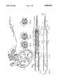
- FIG. 1is a fragmentary schematic diagram showing the pump of the present invention in a typical operative environment in the left ventricle of a human heart which is shown in cross section.
- FIG. 2is a somewhat enlarged, fragmentary side elevation of the pump of the present invention.
- FIG. 3is a longitudinal section taken on line 3--3 in FIG. 2.
- FIG. 4is a transverse section taken on line 4--4 in FIG. 2.
- FIG. 5is a transfer section taken on line 5--5 in FIG. 2.
- FIG. 6is a transverse section taken on line 6--6 in FIG. 2.
- the pump of the present inventionis generally indicated by the numeral 10 in FIG. 1.
- the pump of the present inventionhas application to a wide assortment of specific embodiments and uses. More particularly, the pump can be produced in a size, form and from materials suitable for the pumping of virtually any fluid in any operative environment. However, the pump has particular utility when constructed for intraarterial ventricular insertion to provide a temporary cardiac assist.
- the pumpis shown in FIG. 1 in such a typical operative environment in use in a human heart 11.
- the hearthas a right ventricle generally indicated at 12 and a left ventricle generally indicated at 13.
- the left ventricleencloses a chamber 14.
- the hearthas an aorta 15 which receives blood pumped by the left ventricle.
- the aortahas a passageway 16.
- the left ventricle and aortahave interior surfaces 17.
- the pump 10has an elongated tubular housing 25 which may be constructed of any suitable material. However, for use in the embodiment herein disclosed, the housing and all other components of the pump should be constructed of stainless steel. In the embodiment herein disclosed, the housing has an outer diameter of approximately one-quarter of an inch (1/4") and a length of approximately one-and-one-quarter inch (11/4"). It will be understood that the actual dimensions and materials from which the pump is manufactured can be varied to suit the particular environment within which the pump is to be employed and as otherwise best suited to the operation to be performed. It will be understood, however, that the pump of the present invention constitutes a significant advancement over the art in that the capacity of the pump is substantially greater than has heretofore been possible for a given outer diameter of the housing 25.
- the housing 25has a cylindrical wall 26 having an interior surface 27 and an exterior surface 28.
- the cylindrical wallhas an inlet end portion 29 and an opposite outlet end portion 30.
- the cylindrical wall 26is substantially concentric to a longitudinal axis 31 for the housing 25.
- the pumphas a core member 35 having a mounting plate 36.
- the core memberis mounted within the cylindrical wall in coaxial relation with the cylindrical wall with the mounting plate 36 mounted on the interior surface 27 of the cylindrical wall at the inlet end portion 29 thereof, as best shown in FIG. 3.
- the core memberincludes a convoluted stationary member or fluid vane 37 extending through the housing 25 toward the outlet end portion 30 and wound about the longitudinal axis 31 to form substantially a helix.
- the fluid vanehas a terminal end 38 spaced inwardly of the outlet end portion 30.
- the fluid vanehas marginal edges 39 which are substantially equally spaced from the longitudinal axis 31 to form a passage 40 between the interior surface 27 of the cylindrical wall 26 and the marginal edges.
- the core memberis fixed within the housing so that the fluid vane 37 thereof is similarly fixed relative to the interior surface 27 of the cylindrical wall 26.
- the inlet end portion 29has an inlet passage 41 bounded by the cylindrical wall and passing on both sides of the mounting plate 36.
- the inlet passagecommunicates both with the passage 40 defined between the marginal edges and the interior surface 27 of the housing 25 and with helical paths 42 defined by the fluid vane 37.
- a bearing mounting assembly 45is itself mounted in the outlet end portion 30 of the housing 25 as best shown in FIGS. 3 and 6.
- the bearing mounting assemblyincludes a pair of fluid vanes 46 mounted on the interior surface 27 of the cylindrical wall and extending to and mounting a tubular mount 47 substantially concentric to the longitudinal axis 31 of the cylindrical wall 26.
- a bearing 48is mounted within the tubular mount 47 concentric to the longitudinal axis 31.
- An O-ring 49is mounted within the tubular mount against the bearing on the side thereof facing the interior of the housing 25.
- the outlet end portion 30 of the cylindrical wallthus bounds and defines a discharge passage 50 extending outwardly through the outlet end portion about the tubular mount and on both sides of the fluid vanes 46.
- a drive cable assembly 55having a proximal end portion 56 and an opposite distal end portion 57, is mounted by its proximal end portion in the tubular mount 47 of the bearing mounting assembly 45.
- the drive cable assemblyhas a stationary outer sheath 58 and an internal rotational drive cable 59.
- the drive cablehas a mounting end 60 which extends through the bearing 48 and O-ring 49 and into the interior of the housing 25 in juxtaposition to the terminal end 38 of the fluid vane 37.
- a clevis assembly 61is mounted on the mounting end 60 in coaxial relation to the longitudinal axis 31 and in immediate juxtaposition to the terminal end 38 of the fluid vane 37.
- the pump 10has an impeller 65 best shown in FIG. 3.
- the impellerhas a return bent mounting portion 66 which is mounted on the mounting end 60 of the drive cable 59 by the clevis assembly 61.
- the impellerincludes a pair of impeller rods 67 extending in oppositely wound, spiral courses about the fluid vane 37 of the core member 35 between the marginal edges 39 thereof and the interior surface 27 of the cylindrical wall 26. The impeller rods are thus received within the passage 40 about the fluid vane 37.
- the impeller rods 67extend to terminal ends 68 which are spaced from each other substantially 180 degrees about the longitudinal axis 31, as can best be seen in FIGS. 3 and 5.
- impeller rods 67rotation of the drive cable 59 causes the impeller rods 67 to rotate about the fluid vane 37 in the passage 40 extending thereabout.
- the impellercan, if desired, also be constructed in the form of a single impeller rod, not shown, extending in a spiral course about the fluid vane.
- the distal end portion 57 of the drive cable assembly 55is connected in driven relation to a suitable high speed electric motor 75 adapted to be driven from a suitable source of electrical energy by way of an electric cable 76 fragmentarily shown in FIG. 1.
- the drive cable assembly 55is of a length and of a diameter suitable for extension from the electric motor outside of the body of the patient through the vascular system to the heart 11 as shown in FIG. 1.
- An internal passage 80interconnects the inlet end portion and attachment end portion thus establishing a path for fluid flow from the inlet end portion 79, along the internal passage 80, through the cylindrical wall 26 of the housing 25 and out the discharge passage 50 of the pump. It will be understood that the inlet cannula 77 is sufficiently flexible to permit it to be wound through the vascular system of the patient, but sufficiently rigid to avoid collapsing.
- the pump 10 of the present inventionis adaptable for use in a wide variety of operational environments. However, it has particular utility when used in intraarterial ventricular assistance to supplement the pumping of the human heart. Procedures previously developed, such as set forth in the Wampler U.S. Pat. No. 4,625,712, the Moise U.S. Pat. No. 4,704,121 and the article entitled, "IN VIVO EVALUATION OF A PERIPHERAL VASCULAR ACCESS AXIAL FLOW BLOOD PUMP" appearing in Volume XXXIV Trans Am Soc Artif Intern Organs 1988, can be employed in using the pump for this purpose.
- the pump 10is maneuvered through the vascular system of the patient to locate the inlet cannula 77, housing 25 and proximal end portion 56 of the drive cable assembly 55 within the chamber 14 of the left ventricle 13 and the passageway 16 of the aorta 15, as shown in FIG. 1.
- the electric motor 75is then operated to rotate the impeller 65 of the housing 25 at the desired number of revolutions per minute.
- the impellercan be rotated at any desired velocity suited to the requirements of the circumstances. A velocity of up to twenty thousand revolutions per minute (20,000 RPM) may be preferred depending upon the patient's condition.
- the impeller rods 67move at high speed about the fluid vane 37 of the core member 35 in the passage 40.
- the pumpoperates at significantly higher capacity than conventional pumps to pump blood, within which the pump is submersed, into the inlet end portion 79 of the cannula, through the inlet passage 41, along the passage 40 and the helical paths 42, through the housing 25, out the discharge passage 50 and back into the aorta 15. Such operation supplements the output of the heart thereby relieving the heart muscle from the normal load and permitting the heart muscle to recover and repair itself.
- the pumphas a significantly greater capacity than conventional pumps.
- the shearing action between the stator and rotor of conventional pumpsis not found in the pump of the present invention thereby reducing significantly the trauma caused to the blood by the pumping operation.
- the pump of the present inventionis adaptable to a wide variety of environments, is capable of being produced in a variety of different sizes best suited to the particular jobs to be performed, operates dependably and safely over a virtually unlimited period of operation to pump fluid therethrough, is particularly well suited to intraarterial ventricular assist to the human heart, significantly reduces the trauma caused to the fluid during the pumping operation and is otherwise substantially more efficient than conventional pumping devices.
Landscapes
- Engineering & Computer Science (AREA)
- Health & Medical Sciences (AREA)
- Heart & Thoracic Surgery (AREA)
- Mechanical Engineering (AREA)
- Cardiology (AREA)
- Life Sciences & Earth Sciences (AREA)
- Biomedical Technology (AREA)
- Hematology (AREA)
- Anesthesiology (AREA)
- Animal Behavior & Ethology (AREA)
- General Health & Medical Sciences (AREA)
- Public Health (AREA)
- Veterinary Medicine (AREA)
- General Engineering & Computer Science (AREA)
- Vascular Medicine (AREA)
- Physics & Mathematics (AREA)
- Fluid Mechanics (AREA)
- External Artificial Organs (AREA)
Abstract
Description
Claims (6)
Priority Applications (1)
| Application Number | Priority Date | Filing Date | Title |
|---|---|---|---|
| US07/405,721US5040944A (en) | 1989-09-11 | 1989-09-11 | Pump having impeller rotational about convoluted stationary member |
Applications Claiming Priority (1)
| Application Number | Priority Date | Filing Date | Title |
|---|---|---|---|
| US07/405,721US5040944A (en) | 1989-09-11 | 1989-09-11 | Pump having impeller rotational about convoluted stationary member |
Publications (1)
| Publication Number | Publication Date |
|---|---|
| US5040944Atrue US5040944A (en) | 1991-08-20 |
Family
ID=23604943
Family Applications (1)
| Application Number | Title | Priority Date | Filing Date |
|---|---|---|---|
| US07/405,721Expired - LifetimeUS5040944A (en) | 1989-09-11 | 1989-09-11 | Pump having impeller rotational about convoluted stationary member |
Country Status (1)
| Country | Link |
|---|---|
| US (1) | US5040944A (en) |
Cited By (49)
| Publication number | Priority date | Publication date | Assignee | Title |
|---|---|---|---|---|
| US5300112A (en)* | 1992-07-14 | 1994-04-05 | Aai Corporation | Articulated heart pump |
| US5344385A (en)* | 1991-09-30 | 1994-09-06 | Thoratec Laboratories Corporation | Step-down skeletal muscle energy conversion system |
| US5368438A (en)* | 1993-06-28 | 1994-11-29 | Baxter International Inc. | Blood pump |
| US5527159A (en)* | 1993-11-10 | 1996-06-18 | The United States Of America As Represented By The Administrator Of The National Aeronautics And Space Administration | Rotary blood pump |
| US5643215A (en)* | 1995-02-24 | 1997-07-01 | The Research Foundation Of State University Of New York | Gas exchange apparatus and method |
| US5947892A (en)* | 1993-11-10 | 1999-09-07 | Micromed Technology, Inc. | Rotary blood pump |
| US6245007B1 (en) | 1999-01-28 | 2001-06-12 | Terumo Cardiovascular Systems Corporation | Blood pump |
| US6247892B1 (en) | 1999-07-26 | 2001-06-19 | Impsa International Inc. | Continuous flow rotary pump |
| US6554799B1 (en)* | 1999-09-02 | 2003-04-29 | Center For Advanced Science And Technology Incubation, Ltd. | Biological precision screw pump |
| US6595743B1 (en) | 1999-07-26 | 2003-07-22 | Impsa International Inc. | Hydraulic seal for rotary pumps |
| US6858001B1 (en) | 1997-07-11 | 2005-02-22 | A-Med Systems, Inc. | Single port cardiac support apparatus |
| US20050135942A1 (en)* | 2003-09-25 | 2005-06-23 | Medforte Research Foundation | Streamlined unobstructed one-pass axial-flow pump |
| US20050135948A1 (en)* | 2003-09-25 | 2005-06-23 | Medforte Research Foundation | Axial-flow blood pump with magnetically suspended, radially and axially stabilized impeller |
| US7182727B2 (en) | 1997-07-11 | 2007-02-27 | A—Med Systems Inc. | Single port cardiac support apparatus |
| US7878967B1 (en)* | 2005-10-06 | 2011-02-01 | Sanjaya Khanal | Heart failure/hemodynamic device |
| US8690749B1 (en) | 2009-11-02 | 2014-04-08 | Anthony Nunez | Wireless compressible heart pump |
| US8900060B2 (en) | 2009-04-29 | 2014-12-02 | Ecp Entwicklungsgesellschaft Mbh | Shaft arrangement having a shaft which extends within a fluid-filled casing |
| US8926492B2 (en) | 2011-10-11 | 2015-01-06 | Ecp Entwicklungsgesellschaft Mbh | Housing for a functional element |
| US8932141B2 (en) | 2009-10-23 | 2015-01-13 | Ecp Entwicklungsgesellschaft Mbh | Flexible shaft arrangement |
| US8944748B2 (en) | 2009-05-05 | 2015-02-03 | Ecp Entwicklungsgesellschaft Mbh | Fluid pump changeable in diameter, in particular for medical application |
| US8979493B2 (en) | 2009-03-18 | 2015-03-17 | ECP Entwicklungsgesellscaft mbH | Fluid pump |
| US8998792B2 (en) | 2008-12-05 | 2015-04-07 | Ecp Entwicklungsgesellschaft Mbh | Fluid pump with a rotor |
| US9028216B2 (en) | 2009-09-22 | 2015-05-12 | Ecp Entwicklungsgesellschaft Mbh | Rotor for an axial flow pump for conveying a fluid |
| US9067006B2 (en) | 2009-06-25 | 2015-06-30 | Ecp Entwicklungsgesellschaft Mbh | Compressible and expandable blade for a fluid pump |
| US9089634B2 (en) | 2009-09-22 | 2015-07-28 | Ecp Entwicklungsgesellschaft Mbh | Fluid pump having at least one impeller blade and a support device |
| US9089670B2 (en) | 2009-02-04 | 2015-07-28 | Ecp Entwicklungsgesellschaft Mbh | Catheter device having a catheter and an actuation device |
| US9217442B2 (en) | 2010-03-05 | 2015-12-22 | Ecp Entwicklungsgesellschaft Mbh | Pump or rotary cutter for operation in a fluid |
| US9314558B2 (en) | 2009-12-23 | 2016-04-19 | Ecp Entwicklungsgesellschaft Mbh | Conveying blades for a compressible rotor |
| US9328741B2 (en) | 2010-05-17 | 2016-05-03 | Ecp Entwicklungsgesellschaft Mbh | Pump arrangement |
| US9339596B2 (en) | 2009-12-23 | 2016-05-17 | Ecp Entwicklungsgesellschaft Mbh | Radially compressible and expandable rotor for a fluid pump |
| US9358330B2 (en) | 2009-12-23 | 2016-06-07 | Ecp Entwicklungsgesellschaft Mbh | Pump device having a detection device |
| US9416791B2 (en) | 2010-01-25 | 2016-08-16 | Ecp Entwicklungsgesellschaft Mbh | Fluid pump having a radially compressible rotor |
| US9416783B2 (en) | 2009-09-22 | 2016-08-16 | Ecp Entwicklungsgellschaft Mbh | Compressible rotor for a fluid pump |
| US9603983B2 (en) | 2009-10-23 | 2017-03-28 | Ecp Entwicklungsgesellschaft Mbh | Catheter pump arrangement and flexible shaft arrangement having a core |
| US9611743B2 (en) | 2010-07-15 | 2017-04-04 | Ecp Entwicklungsgesellschaft Mbh | Radially compressible and expandable rotor for a pump having an impeller blade |
| EP3153191A1 (en)* | 2015-10-09 | 2017-04-12 | ECP Entwicklungsgesellschaft mbH | Blood pump |
| US9771801B2 (en) | 2010-07-15 | 2017-09-26 | Ecp Entwicklungsgesellschaft Mbh | Rotor for a pump, produced with a first elastic material |
| US9867916B2 (en) | 2010-08-27 | 2018-01-16 | Berlin Heart Gmbh | Implantable blood conveying device, manipulating device and coupling device |
| US9895475B2 (en) | 2010-07-15 | 2018-02-20 | Ecp Entwicklungsgesellschaft Mbh | Blood pump for the invasive application within a body of a patient |
| US9974893B2 (en) | 2010-06-25 | 2018-05-22 | Ecp Entwicklungsgesellschaft Mbh | System for introducing a pump |
| US10107299B2 (en) | 2009-09-22 | 2018-10-23 | Ecp Entwicklungsgesellschaft Mbh | Functional element, in particular fluid pump, having a housing and a conveying element |
| US10172985B2 (en) | 2009-08-06 | 2019-01-08 | Ecp Entwicklungsgesellschaft Mbh | Catheter device having a coupling device for a drive device |
| US10238783B2 (en) | 1999-09-03 | 2019-03-26 | Maquet Cardiovascular Llc | Guidable intravascular blood pump and related methods |
| US10322222B2 (en) | 2015-07-10 | 2019-06-18 | Terumo Cardiovascular Systems Corporation | Integrated medical pump and oxygenator |
| US10391278B2 (en) | 2011-03-10 | 2019-08-27 | Ecp Entwicklungsgesellschaft Mbh | Push device for the axial insertion of an elongate, flexible body |
| US10561773B2 (en) | 2011-09-05 | 2020-02-18 | Ecp Entwicklungsgesellschaft Mbh | Medical product comprising a functional element for the invasive use in a patient's body |
| US12128228B2 (en) | 2019-05-23 | 2024-10-29 | Magenta Medical Ltd | Blood pumps |
| US12390631B2 (en)* | 2015-05-18 | 2025-08-19 | Magenta Medical Ltd. | Blood pump |
| US12414851B2 (en) | 2013-03-13 | 2025-09-16 | Magenta Medical Ltd | Impeller for blood pump |
Citations (13)
| Publication number | Priority date | Publication date | Assignee | Title |
|---|---|---|---|---|
| US536925A (en)* | 1895-04-02 | Paeis erb | ||
| US589532A (en)* | 1897-09-07 | Lifting or irrigating pump | ||
| US1111722A (en)* | 1910-11-16 | 1914-09-22 | James H Sheahan | Water-motor. |
| US1273913A (en)* | 1917-03-15 | 1918-07-30 | Pontus Ostenberg | Centrifugal pump. |
| US1378891A (en)* | 1920-03-01 | 1921-05-24 | Paul H Musswitz | Rotary pump |
| US1581683A (en)* | 1924-11-07 | 1926-04-20 | William T Nicholls | Centrifugal water motor |
| US2256659A (en)* | 1940-06-25 | 1941-09-23 | Leo R Thrasher | Deep well pump motor |
| US2633290A (en)* | 1950-05-13 | 1953-03-31 | Henry G Schaefer | Vacuum pump with expanding liquid spiral |
| US2893688A (en)* | 1956-07-02 | 1959-07-07 | Bellows Electric Sign Corp | Fluid power motor valve |
| US3266555A (en)* | 1962-09-05 | 1966-08-16 | Huels Chemische Werke Ag | Rotating coil distributor-conveyor for cylindrical film evaporator |
| US3880548A (en)* | 1972-01-06 | 1975-04-29 | Jr Raymond L Kirby | Ink pump |
| US4625712A (en)* | 1983-09-28 | 1986-12-02 | Nimbus, Inc. | High-capacity intravascular blood pump utilizing percutaneous access |
| US4704121A (en)* | 1983-09-28 | 1987-11-03 | Nimbus, Inc. | Anti-thrombogenic blood pump |
- 1989
- 1989-09-11USUS07/405,721patent/US5040944A/ennot_activeExpired - Lifetime
Patent Citations (13)
| Publication number | Priority date | Publication date | Assignee | Title |
|---|---|---|---|---|
| US536925A (en)* | 1895-04-02 | Paeis erb | ||
| US589532A (en)* | 1897-09-07 | Lifting or irrigating pump | ||
| US1111722A (en)* | 1910-11-16 | 1914-09-22 | James H Sheahan | Water-motor. |
| US1273913A (en)* | 1917-03-15 | 1918-07-30 | Pontus Ostenberg | Centrifugal pump. |
| US1378891A (en)* | 1920-03-01 | 1921-05-24 | Paul H Musswitz | Rotary pump |
| US1581683A (en)* | 1924-11-07 | 1926-04-20 | William T Nicholls | Centrifugal water motor |
| US2256659A (en)* | 1940-06-25 | 1941-09-23 | Leo R Thrasher | Deep well pump motor |
| US2633290A (en)* | 1950-05-13 | 1953-03-31 | Henry G Schaefer | Vacuum pump with expanding liquid spiral |
| US2893688A (en)* | 1956-07-02 | 1959-07-07 | Bellows Electric Sign Corp | Fluid power motor valve |
| US3266555A (en)* | 1962-09-05 | 1966-08-16 | Huels Chemische Werke Ag | Rotating coil distributor-conveyor for cylindrical film evaporator |
| US3880548A (en)* | 1972-01-06 | 1975-04-29 | Jr Raymond L Kirby | Ink pump |
| US4625712A (en)* | 1983-09-28 | 1986-12-02 | Nimbus, Inc. | High-capacity intravascular blood pump utilizing percutaneous access |
| US4704121A (en)* | 1983-09-28 | 1987-11-03 | Nimbus, Inc. | Anti-thrombogenic blood pump |
Non-Patent Citations (6)
| Title |
|---|
| "Hemopom®" Johnson & Johnson, 1988, pp. 1-14. |
| "Medicine", feature from Time, 16 May 1987. |
| Hemopom Johnson & Johnson, 1988, pp. 1 14.* |
| Medicine , feature from Time, 16 May 1987.* |
| Wampler et al., "Transactions of the American Society for Artificial Internal Organs", vol. 34, No. 3, Jul.-Sep. 1988, pp. 450-454. |
| Wampler et al., Transactions of the American Society for Artificial Internal Organs , vol. 34, No. 3, Jul. Sep. 1988, pp. 450 454.* |
Cited By (143)
| Publication number | Priority date | Publication date | Assignee | Title |
|---|---|---|---|---|
| US5701919A (en)* | 1991-09-30 | 1997-12-30 | Thoratec Laboratories Corporation | Step-down skeletal muscle energy conversion system |
| US5344385A (en)* | 1991-09-30 | 1994-09-06 | Thoratec Laboratories Corporation | Step-down skeletal muscle energy conversion system |
| US5984857A (en)* | 1991-09-30 | 1999-11-16 | Thoratec Laboratories Corporation | Step-down skeletal muscle energy conversion system |
| US5653676A (en)* | 1991-09-30 | 1997-08-05 | Thoratec Laboratories Corporation | Step-down skeletal muscle energy conversion method |
| US5405383A (en)* | 1992-07-14 | 1995-04-11 | Aai Corporation | Articulated heart pump and method of use |
| US5300112A (en)* | 1992-07-14 | 1994-04-05 | Aai Corporation | Articulated heart pump |
| US5368438A (en)* | 1993-06-28 | 1994-11-29 | Baxter International Inc. | Blood pump |
| WO1995000186A1 (en)* | 1993-06-28 | 1995-01-05 | Baxter International Inc. | Blood pump |
| US5501574A (en)* | 1993-06-28 | 1996-03-26 | Baxter International Inc. | Blood pump |
| US5692882A (en)* | 1993-11-10 | 1997-12-02 | The United States Of America As Represented By The Administrator Of The National Aeronautics And Space Administration | Axial pump |
| US5678306A (en)* | 1993-11-10 | 1997-10-21 | The United States Of America As Represented By The Administrator Of The National Aeronautics And Space Administration | Method for reducing pumping damage to blood |
| US5947892A (en)* | 1993-11-10 | 1999-09-07 | Micromed Technology, Inc. | Rotary blood pump |
| US5527159A (en)* | 1993-11-10 | 1996-06-18 | The United States Of America As Represented By The Administrator Of The National Aeronautics And Space Administration | Rotary blood pump |
| US5643215A (en)* | 1995-02-24 | 1997-07-01 | The Research Foundation Of State University Of New York | Gas exchange apparatus and method |
| US6858001B1 (en) | 1997-07-11 | 2005-02-22 | A-Med Systems, Inc. | Single port cardiac support apparatus |
| US7182727B2 (en) | 1997-07-11 | 2007-02-27 | A—Med Systems Inc. | Single port cardiac support apparatus |
| US20060069299A1 (en)* | 1997-09-19 | 2006-03-30 | A-Med Systems, Inc. | Integrated pump and cannula systems and related methods |
| US6245007B1 (en) | 1999-01-28 | 2001-06-12 | Terumo Cardiovascular Systems Corporation | Blood pump |
| US6247892B1 (en) | 1999-07-26 | 2001-06-19 | Impsa International Inc. | Continuous flow rotary pump |
| US6595743B1 (en) | 1999-07-26 | 2003-07-22 | Impsa International Inc. | Hydraulic seal for rotary pumps |
| US6554799B1 (en)* | 1999-09-02 | 2003-04-29 | Center For Advanced Science And Technology Incubation, Ltd. | Biological precision screw pump |
| US10300186B2 (en) | 1999-09-03 | 2019-05-28 | Maquet Cardiovascular Llc | Guidable intravascular blood pump and related methods |
| US10238783B2 (en) | 1999-09-03 | 2019-03-26 | Maquet Cardiovascular Llc | Guidable intravascular blood pump and related methods |
| US10357598B2 (en) | 1999-09-03 | 2019-07-23 | Maquet Cardiovascular Llc | Guidable intravascular blood pump and related methods |
| US10279095B2 (en) | 1999-09-03 | 2019-05-07 | Maquet Cardiovascular Llc | Guidable intravascular blood pump and related methods |
| US10328191B2 (en) | 1999-09-03 | 2019-06-25 | Maquet Cardiovascular Llc | Guidable intravascular blood pump and related methods |
| US10300185B2 (en) | 1999-09-03 | 2019-05-28 | Maquet Cardiovascular Llc | Guidable intravascular blood pump and related methods |
| US10322218B2 (en) | 1999-09-03 | 2019-06-18 | Maquet Cardiovascular Llc | Guidable intravascular blood pump and related methods |
| US20050135942A1 (en)* | 2003-09-25 | 2005-06-23 | Medforte Research Foundation | Streamlined unobstructed one-pass axial-flow pump |
| US20050135948A1 (en)* | 2003-09-25 | 2005-06-23 | Medforte Research Foundation | Axial-flow blood pump with magnetically suspended, radially and axially stabilized impeller |
| US7229258B2 (en) | 2003-09-25 | 2007-06-12 | Medforte Research Foundation | Streamlined unobstructed one-pass axial-flow pump |
| US7070398B2 (en) | 2003-09-25 | 2006-07-04 | Medforte Research Foundation | Axial-flow blood pump with magnetically suspended, radially and axially stabilized impeller |
| US7878967B1 (en)* | 2005-10-06 | 2011-02-01 | Sanjaya Khanal | Heart failure/hemodynamic device |
| US9964115B2 (en) | 2008-12-05 | 2018-05-08 | Ecp Entwicklungsgesellschaft Mbh | Fluid pump with a rotor |
| US11852155B2 (en) | 2008-12-05 | 2023-12-26 | Ecp Entwicklungsgesellschaft Mbh | Fluid pump with a rotor |
| US8998792B2 (en) | 2008-12-05 | 2015-04-07 | Ecp Entwicklungsgesellschaft Mbh | Fluid pump with a rotor |
| US10662967B2 (en) | 2008-12-05 | 2020-05-26 | Ecp Entwicklungsgesellschaft Mbh | Fluid pump with a rotor |
| US12209593B2 (en) | 2008-12-05 | 2025-01-28 | Ecp Entwicklungsgesellschaft Mbh | Fluid pump with a rotor |
| US9404505B2 (en) | 2008-12-05 | 2016-08-02 | Ecp Entwicklungsgesellschaft Mbh | Fluid pump with a rotor |
| US10495101B2 (en) | 2008-12-05 | 2019-12-03 | Ecp Entwicklungsgesellschaft Mbh | Fluid pump with a rotor |
| US12377246B2 (en) | 2009-02-04 | 2025-08-05 | Ecp Entwicklungsgesellschaft Mbh | Catheter device having a catheter and an actuation device |
| US9649475B2 (en) | 2009-02-04 | 2017-05-16 | Ecp Entwicklungsgesellschaft Mbh | Catheter device having a catheter and an actuation device |
| US9981110B2 (en) | 2009-02-04 | 2018-05-29 | Ecp Entwicklungsgesellschaft Mbh | Catheter device having a catheter and an actuation device |
| US10406323B2 (en) | 2009-02-04 | 2019-09-10 | Ecp Entwicklungsgesellschaft Mbh | Catheter device having a catheter and an actuation device |
| US11229774B2 (en) | 2009-02-04 | 2022-01-25 | Ecp Entwicklungsgesellschaft Mbh | Catheter device having a catheter and an actuation device |
| US9089670B2 (en) | 2009-02-04 | 2015-07-28 | Ecp Entwicklungsgesellschaft Mbh | Catheter device having a catheter and an actuation device |
| US11969560B2 (en) | 2009-02-04 | 2024-04-30 | Ecp Entwicklungsgesellschaft Mbh | Catheter device having a catheter and an actuation device |
| US8979493B2 (en) | 2009-03-18 | 2015-03-17 | ECP Entwicklungsgesellscaft mbH | Fluid pump |
| US8900060B2 (en) | 2009-04-29 | 2014-12-02 | Ecp Entwicklungsgesellschaft Mbh | Shaft arrangement having a shaft which extends within a fluid-filled casing |
| US11577066B2 (en) | 2009-05-05 | 2023-02-14 | Ecp Entwicklundgesellschaft Mbh | Fluid pump changeable in diameter, in particular for medical application |
| US8944748B2 (en) | 2009-05-05 | 2015-02-03 | Ecp Entwicklungsgesellschaft Mbh | Fluid pump changeable in diameter, in particular for medical application |
| US11786718B2 (en) | 2009-05-05 | 2023-10-17 | Ecp Entwicklungsgesellschaft Mbh | Fluid pump changeable in diameter, in particular for medical application |
| US10265448B2 (en) | 2009-05-05 | 2019-04-23 | Ecp Entwicklungsgesellschaft Mbh | Fluid pump changeable in diameter, in particular for medical application |
| US9512839B2 (en) | 2009-05-05 | 2016-12-06 | Ecp Entwicklungsgesellschaft Mbh | Fluid pump changeable in diameter, in particular for medical application |
| US11278711B2 (en) | 2009-05-05 | 2022-03-22 | Ecp Entwicklungsgesellschaft Mbh | Fluid pump changeable in diameter, in particular for medical application |
| US9067006B2 (en) | 2009-06-25 | 2015-06-30 | Ecp Entwicklungsgesellschaft Mbh | Compressible and expandable blade for a fluid pump |
| US10330101B2 (en) | 2009-06-25 | 2019-06-25 | Ecp Entwicklungsgesellschaft Mbh | Compressible and expandable blade for a fluid pump |
| US11268521B2 (en) | 2009-06-25 | 2022-03-08 | Ecp Entwicklungsgesellschaft Mbh | Compressible and expandable blade for a fluid pump |
| US12372092B2 (en) | 2009-06-25 | 2025-07-29 | Ecp Entwicklungsgesellschaft Mbh | Compressible and expandable blade for a fluid pump |
| US11994133B2 (en) | 2009-06-25 | 2024-05-28 | Ecp Entwicklungsgesellschaft Mbh | Compressible and expandable blade for a fluid pump |
| US10172985B2 (en) | 2009-08-06 | 2019-01-08 | Ecp Entwicklungsgesellschaft Mbh | Catheter device having a coupling device for a drive device |
| US11116960B2 (en) | 2009-08-06 | 2021-09-14 | Ecp Entwicklungsgesellschaft Mbh | Catheter device having a coupling device for a drive device |
| US12042647B2 (en) | 2009-08-06 | 2024-07-23 | Ecp Entwicklungsgesellschaft Mbh | Catheter device having a coupling device for a drive device |
| US10208763B2 (en) | 2009-09-22 | 2019-02-19 | Ecp Entwicklungsgesellschaft Mbh | Fluid pump having at least one impeller blade and a support device |
| US10107299B2 (en) | 2009-09-22 | 2018-10-23 | Ecp Entwicklungsgesellschaft Mbh | Functional element, in particular fluid pump, having a housing and a conveying element |
| US11592028B2 (en) | 2009-09-22 | 2023-02-28 | Ecp Entwicklungsgesellschaft Mbh | Fluid pump having at least one impeller blade and a support device |
| US11421701B2 (en) | 2009-09-22 | 2022-08-23 | Ecp Entwicklungsgesellschaft Mbh | Compressible rotor for a fluid pump |
| US9089634B2 (en) | 2009-09-22 | 2015-07-28 | Ecp Entwicklungsgesellschaft Mbh | Fluid pump having at least one impeller blade and a support device |
| US9028216B2 (en) | 2009-09-22 | 2015-05-12 | Ecp Entwicklungsgesellschaft Mbh | Rotor for an axial flow pump for conveying a fluid |
| US12276285B2 (en) | 2009-09-22 | 2025-04-15 | Ecp Entwicklungsgesellschaft Mbh | Compressible rotor for a fluid pump |
| US12066030B2 (en) | 2009-09-22 | 2024-08-20 | Ecp Entwicklungsgesellschaft Mbh | Fluid pump having at least one impeller blade and a support device |
| US9416783B2 (en) | 2009-09-22 | 2016-08-16 | Ecp Entwicklungsgellschaft Mbh | Compressible rotor for a fluid pump |
| US11773861B2 (en) | 2009-09-22 | 2023-10-03 | Ecp Entwicklungsgesellschaft Mbh | Compressible rotor for a fluid pump |
| US12313113B2 (en) | 2009-10-23 | 2025-05-27 | Ecp Entwicklungsgesellschaft Mbh | Catheter pump arrangement and flexible shaft arrangement having a core |
| US10792406B2 (en) | 2009-10-23 | 2020-10-06 | Ecp Entwicklungsgesellschaft Mbh | Catheter pump arrangement and flexible shaft arrangement having a core |
| US9603983B2 (en) | 2009-10-23 | 2017-03-28 | Ecp Entwicklungsgesellschaft Mbh | Catheter pump arrangement and flexible shaft arrangement having a core |
| US8932141B2 (en) | 2009-10-23 | 2015-01-13 | Ecp Entwicklungsgesellschaft Mbh | Flexible shaft arrangement |
| US8690749B1 (en) | 2009-11-02 | 2014-04-08 | Anthony Nunez | Wireless compressible heart pump |
| US10561772B2 (en) | 2009-12-23 | 2020-02-18 | Ecp Entwicklungsgesellschaft Mbh | Pump device having a detection device |
| US12158151B2 (en) | 2009-12-23 | 2024-12-03 | Ecp Entwicklungsgesellschaft Mbh | Pump device having a detection device |
| US9358330B2 (en) | 2009-12-23 | 2016-06-07 | Ecp Entwicklungsgesellschaft Mbh | Pump device having a detection device |
| US10557475B2 (en) | 2009-12-23 | 2020-02-11 | Ecp Entwicklungsgesellschaft Mbh | Radially compressible and expandable rotor for a fluid pump |
| US11773863B2 (en) | 2009-12-23 | 2023-10-03 | Ecp Entwicklungsgesellschaft Mbh | Conveying blades for a compressible rotor |
| US11781557B2 (en) | 2009-12-23 | 2023-10-10 | Ecp Entwicklungsgesellschaft Mbh | Radially compressible and expandable rotor for a fluid pump |
| US11815097B2 (en) | 2009-12-23 | 2023-11-14 | Ecp Entwicklungsgesellschaft Mbh | Pump device having a detection device |
| US12085088B2 (en) | 2009-12-23 | 2024-09-10 | Ecp Entwicklungsgesellschaft Mbh | Radially compressible and expandable rotor for a fluid pump |
| US11549517B2 (en) | 2009-12-23 | 2023-01-10 | Ecp Entwicklungsgesellschaft Mbh | Conveying blades for a compressible rotor |
| US9339596B2 (en) | 2009-12-23 | 2016-05-17 | Ecp Entwicklungsgesellschaft Mbh | Radially compressible and expandable rotor for a fluid pump |
| US12117014B2 (en) | 2009-12-23 | 2024-10-15 | Ecp Entwicklungsgesellschaft Mbh | Conveying blades for a compressible rotor |
| US10806838B2 (en) | 2009-12-23 | 2020-10-20 | Ecp Entwicklungsgesellschaft Mbh | Conveying blades for a compressible rotor |
| US11486400B2 (en) | 2009-12-23 | 2022-11-01 | Ecp Entwicklungsgesellschaft Mbh | Pump device having a detection device |
| US11434922B2 (en) | 2009-12-23 | 2022-09-06 | Ecp Entwicklungsgesellschaft Mbh | Radially compressible and expandable rotor for a fluid pump |
| US9795727B2 (en) | 2009-12-23 | 2017-10-24 | Ecp Entwicklungsgesellschaft Mbh | Pump device having a detection device |
| US9314558B2 (en) | 2009-12-23 | 2016-04-19 | Ecp Entwicklungsgesellschaft Mbh | Conveying blades for a compressible rotor |
| US12305662B2 (en) | 2009-12-23 | 2025-05-20 | Ecp Entwicklungsgesellschaft Mbh | Conveying blades for a compressible rotor |
| US11266824B2 (en) | 2009-12-23 | 2022-03-08 | Ecp Entwicklungsgesellschaft Mbh | Conveying blades for a compressible rotor |
| US9903384B2 (en) | 2009-12-23 | 2018-02-27 | Ecp Entwicklungsgesellschaft Mbh | Radially compressible and expandable rotor for a fluid pump |
| US10316853B2 (en) | 2010-01-25 | 2019-06-11 | Ecp Entwicklungsgesellschaft Mbh | Fluid pump having a radially compressible rotor |
| US11517739B2 (en) | 2010-01-25 | 2022-12-06 | Ecp Entwicklungsgesellschaft Mbh | Fluid pump having a radially compressible rotor |
| US9416791B2 (en) | 2010-01-25 | 2016-08-16 | Ecp Entwicklungsgesellschaft Mbh | Fluid pump having a radially compressible rotor |
| US12018698B2 (en) | 2010-01-25 | 2024-06-25 | Ecp Entwicklungsgesellschaft Mbh | Fluid pump having a radially compressible rotor |
| US10413646B2 (en) | 2010-03-05 | 2019-09-17 | Ecp Entwicklungsgesellschaft Mbh | Pump or rotary cutter for operation in a fluid |
| US9907891B2 (en) | 2010-03-05 | 2018-03-06 | Ecp Entwicklungsgesellschaft Mbh | Pump or rotary cutter for operation in a fluid |
| US11986205B2 (en) | 2010-03-05 | 2024-05-21 | Ecp Entwicklungsgesellschaft Mbh | Pump or rotary cutter for operation in a fluid |
| US9217442B2 (en) | 2010-03-05 | 2015-12-22 | Ecp Entwicklungsgesellschaft Mbh | Pump or rotary cutter for operation in a fluid |
| US9759237B2 (en) | 2010-05-17 | 2017-09-12 | Ecp Entwicklungsgesellschaft Mbh | Pump arrangement |
| US11976674B2 (en) | 2010-05-17 | 2024-05-07 | Ecp Entwicklungsgesellschaft Mbh | Pump arrangement |
| US11168705B2 (en) | 2010-05-17 | 2021-11-09 | Ecp Entwicklungsgesellschaft Mbh | Pump arrangement |
| US9328741B2 (en) | 2010-05-17 | 2016-05-03 | Ecp Entwicklungsgesellschaft Mbh | Pump arrangement |
| US10221866B2 (en) | 2010-05-17 | 2019-03-05 | Ecp Entwicklungsgesellschaft Mbh | Pump arrangement |
| US11957846B2 (en) | 2010-06-25 | 2024-04-16 | Ecp Entwicklungsgesellschaft Mbh | System for introducing a pump |
| US9974893B2 (en) | 2010-06-25 | 2018-05-22 | Ecp Entwicklungsgesellschaft Mbh | System for introducing a pump |
| US10874781B2 (en) | 2010-06-25 | 2020-12-29 | Ecp Entwicklungsgesellschaft Mbh | System for introducing a pump |
| US10898625B2 (en) | 2010-06-25 | 2021-01-26 | Ecp Entwicklungsgesellschaft Mbh | System for introducing a pump |
| US11844939B2 (en) | 2010-07-15 | 2023-12-19 | Ecp Entwicklungsgesellschaft Mbh | Blood pump for the invasive application within a body of a patient |
| US10589012B2 (en) | 2010-07-15 | 2020-03-17 | Ecp Entwicklungsgesellschaft Mbh | Blood pump for the invasive application within a body of a patient |
| US9895475B2 (en) | 2010-07-15 | 2018-02-20 | Ecp Entwicklungsgesellschaft Mbh | Blood pump for the invasive application within a body of a patient |
| US9771801B2 (en) | 2010-07-15 | 2017-09-26 | Ecp Entwicklungsgesellschaft Mbh | Rotor for a pump, produced with a first elastic material |
| US9611743B2 (en) | 2010-07-15 | 2017-04-04 | Ecp Entwicklungsgesellschaft Mbh | Radially compressible and expandable rotor for a pump having an impeller blade |
| US12065941B2 (en) | 2010-07-15 | 2024-08-20 | Ecp Entwicklungsgesellschaft Mbh | Rotor for a pump, produced with a first elastic material |
| US11913467B2 (en) | 2010-07-15 | 2024-02-27 | Ecp Entwicklungsgesellschaft Mbh | Radially compressible and expandable rotor for a pump having an impeller blade |
| US10584589B2 (en) | 2010-07-15 | 2020-03-10 | Ecp Entwicklungsgellschaft Mbh | Rotor for a pump having helical expandable blades |
| US11702938B2 (en) | 2010-07-15 | 2023-07-18 | Ecp Entwicklungsgesellschaft Mbh | Rotor for a pump, produced with a first elastic material |
| US10920596B2 (en) | 2010-07-15 | 2021-02-16 | Ecp Entwicklungsgesellschaft Mbh | Radially compressible and expandable rotor for a pump having an impeller blade |
| US11083885B2 (en) | 2010-08-27 | 2021-08-10 | Berlin Heart Gmbh | Implantable blood conveying device, manipulating device and coupling device |
| US9867916B2 (en) | 2010-08-27 | 2018-01-16 | Berlin Heart Gmbh | Implantable blood conveying device, manipulating device and coupling device |
| US10391278B2 (en) | 2011-03-10 | 2019-08-27 | Ecp Entwicklungsgesellschaft Mbh | Push device for the axial insertion of an elongate, flexible body |
| US11235125B2 (en) | 2011-03-10 | 2022-02-01 | Ecp Entwicklungsgesellschaft Mbh | Push device for the axial insertion of an elongate, flexible body |
| US10561773B2 (en) | 2011-09-05 | 2020-02-18 | Ecp Entwicklungsgesellschaft Mbh | Medical product comprising a functional element for the invasive use in a patient's body |
| US11666746B2 (en) | 2011-09-05 | 2023-06-06 | Ecp Entwicklungsgesellschaft Mbh | Medical product comprising a functional element for the invasive use in a patient's body |
| US8926492B2 (en) | 2011-10-11 | 2015-01-06 | Ecp Entwicklungsgesellschaft Mbh | Housing for a functional element |
| US12414851B2 (en) | 2013-03-13 | 2025-09-16 | Magenta Medical Ltd | Impeller for blood pump |
| US12390631B2 (en)* | 2015-05-18 | 2025-08-19 | Magenta Medical Ltd. | Blood pump |
| US10322222B2 (en) | 2015-07-10 | 2019-06-18 | Terumo Cardiovascular Systems Corporation | Integrated medical pump and oxygenator |
| EP3153191A1 (en)* | 2015-10-09 | 2017-04-12 | ECP Entwicklungsgesellschaft mbH | Blood pump |
| WO2017060254A1 (en)* | 2015-10-09 | 2017-04-13 | Ecp Entwicklungsgesellschaft Mbh | Blood pump |
| US12290674B2 (en) | 2015-10-09 | 2025-05-06 | Ecp Entwicklungsgesellschaft Mbh | Blood pump |
| US11826501B2 (en) | 2015-10-09 | 2023-11-28 | Ecp Entwicklungsgesellschaft Mbh | Blood pump |
| CN108136090A (en)* | 2015-10-09 | 2018-06-08 | Ecp发展有限责任公司 | Blood pump |
| EP3628344A1 (en)* | 2015-10-09 | 2020-04-01 | ECP Entwicklungsgesellschaft mbH | Blood pump |
| US11219755B2 (en) | 2015-10-09 | 2022-01-11 | Ecp Entwicklungsgesellschaft Mbh | Blood pump |
| CN108136090B (en)* | 2015-10-09 | 2021-09-03 | Ecp发展有限责任公司 | Blood pump |
| US12128228B2 (en) | 2019-05-23 | 2024-10-29 | Magenta Medical Ltd | Blood pumps |
Similar Documents
| Publication | Publication Date | Title |
|---|---|---|
| US5040944A (en) | Pump having impeller rotational about convoluted stationary member | |
| US12092114B2 (en) | Purge-free miniature rotary pump | |
| GB2383540A (en) | Intravascular pump | |
| US5092844A (en) | Intracatheter perfusion pump apparatus and method | |
| EP2061531B1 (en) | Intravascular blood pump and catheter | |
| CN112533662A (en) | Intravascular pump with proximal and distal pressure or flow sensors and distal sensor tracking | |
| US5749855A (en) | Catheter pump | |
| US5964694A (en) | Method and apparatus for cardiac blood flow assistance | |
| US5163910A (en) | Intracatheter perfusion pump apparatus and method | |
| US4986807A (en) | Atherectomy cutter with radially projecting blade | |
| US6143009A (en) | Flexible-agitator system and method | |
| US5911685A (en) | Method and apparatus for cardiac blood flow assistance | |
| EP0560000A2 (en) | Ventricular pumping device | |
| JPH08504621A (en) | Temporary cardiac support cannula pump | |
| US20230086096A1 (en) | Intravascular blood pump | |
| US20220040458A1 (en) | Mechanized surgical drain and method of use | |
| RU2051695C1 (en) | Circulatory assist axial-flow impeller pump | |
| CN116785582B (en) | Foldable catheter pump | |
| EP1150612A1 (en) | Flexible-agitator system and method | |
| CN114915109A (en) | heart surgery pump motor | |
| CN118043104A (en) | System and method for pump assisted blood circulation | |
| CN218165800U (en) | Medical ventricular assist device | |
| CN222871168U (en) | Blood pumping device and motor | |
| CN116870356A (en) | Catheter pump assembly and control system thereof | |
| HK40037868A (en) | Purge-free miniature rotary pump |
Legal Events
| Date | Code | Title | Description |
|---|---|---|---|
| STCF | Information on status: patent grant | Free format text:PATENTED CASE | |
| FEPP | Fee payment procedure | Free format text:PAYOR NUMBER ASSIGNED (ORIGINAL EVENT CODE: ASPN); ENTITY STATUS OF PATENT OWNER: LARGE ENTITY | |
| CC | Certificate of correction | ||
| AS | Assignment | Owner name:COOK, JERRY E., EXECTUOR, CALIFORNIA Free format text:ASSIGNMENT OF ASSIGNORS INTEREST;ASSIGNOR:COOK, EINAR P., DECEDENT;REEL/FRAME:007038/0132 Effective date:19930319 | |
| AS | Assignment | Owner name:K.J.J. COOK LAND COMPANY, CALIFORNIA Free format text:ASSIGNMENT OF ASSIGNORS INTEREST;ASSIGNOR:COOK, JERRY E.;REEL/FRAME:007038/0140 Effective date:19930319 | |
| FPAY | Fee payment | Year of fee payment:4 | |
| FEPP | Fee payment procedure | Free format text:PAT HLDR NO LONGER CLAIMS SMALL ENT STAT AS INDIV INVENTOR (ORIGINAL EVENT CODE: LSM1); ENTITY STATUS OF PATENT OWNER: LARGE ENTITY | |
| FPAY | Fee payment | Year of fee payment:8 | |
| FEPP | Fee payment procedure | Free format text:PAYER NUMBER DE-ASSIGNED (ORIGINAL EVENT CODE: RMPN); ENTITY STATUS OF PATENT OWNER: LARGE ENTITY Free format text:PAYOR NUMBER ASSIGNED (ORIGINAL EVENT CODE: ASPN); ENTITY STATUS OF PATENT OWNER: LARGE ENTITY | |
| FPAY | Fee payment | Year of fee payment:12 |