US5040175A - Wireless information transmission system - Google Patents
Wireless information transmission systemDownload PDFInfo
- Publication number
- US5040175A US5040175AUS07/507,558US50755890AUS5040175AUS 5040175 AUS5040175 AUS 5040175AUS 50755890 AUS50755890 AUS 50755890AUS 5040175 AUS5040175 AUS 5040175A
- Authority
- US
- United States
- Prior art keywords
- transmitting
- distribution system
- collision
- packet
- local area
- Prior art date
- Legal status (The legal status is an assumption and is not a legal conclusion. Google has not performed a legal analysis and makes no representation as to the accuracy of the status listed.)
- Expired - Lifetime
Links
Images


Classifications
- H—ELECTRICITY
- H04—ELECTRIC COMMUNICATION TECHNIQUE
- H04W—WIRELESS COMMUNICATION NETWORKS
- H04W24/00—Supervisory, monitoring or testing arrangements
- H—ELECTRICITY
- H04—ELECTRIC COMMUNICATION TECHNIQUE
- H04L—TRANSMISSION OF DIGITAL INFORMATION, e.g. TELEGRAPHIC COMMUNICATION
- H04L1/00—Arrangements for detecting or preventing errors in the information received
- H04L1/12—Arrangements for detecting or preventing errors in the information received by using return channel
- H04L1/14—Arrangements for detecting or preventing errors in the information received by using return channel in which the signals are sent back to the transmitter to be checked ; echo systems
- H—ELECTRICITY
- H04—ELECTRIC COMMUNICATION TECHNIQUE
- H04L—TRANSMISSION OF DIGITAL INFORMATION, e.g. TELEGRAPHIC COMMUNICATION
- H04L12/00—Data switching networks
- H04L12/28—Data switching networks characterised by path configuration, e.g. LAN [Local Area Networks] or WAN [Wide Area Networks]
- H04L12/40—Bus networks
- H04L12/407—Bus networks with decentralised control
- H04L12/413—Bus networks with decentralised control with random access, e.g. carrier-sense multiple-access with collision detection [CSMA-CD]
- H—ELECTRICITY
- H04—ELECTRIC COMMUNICATION TECHNIQUE
- H04W—WIRELESS COMMUNICATION NETWORKS
- H04W48/00—Access restriction; Network selection; Access point selection
- H04W48/08—Access restriction or access information delivery, e.g. discovery data delivery
- H—ELECTRICITY
- H04—ELECTRIC COMMUNICATION TECHNIQUE
- H04W—WIRELESS COMMUNICATION NETWORKS
- H04W84/00—Network topologies
- H04W84/02—Hierarchically pre-organised networks, e.g. paging networks, cellular networks, WLAN [Wireless Local Area Network] or WLL [Wireless Local Loop]
- H04W84/10—Small scale networks; Flat hierarchical networks
- H04W84/12—WLAN [Wireless Local Area Networks]
Definitions
- This inventionrelates to a method of transmitting information between a plurality of stations in a local area network.
- CSMA/CDcarrier sense multiple access/collision detect
- a station wishing to transmit a messagelistens until the transmission channel is idle before commencing to transmit an information packet. Furthermore, the station continues to listen to the channel after commencing a transmission and if a collision is detected, that is, more than one station has commenced to transmit an information packet, any station which detects such collision terminates its message transmission and transmits a burst of noise (or garble) such that all other stations can be informed of the collision, terminate message transmission, and wait a random time before attempting to commence a further message transmission.
- CSMA/CDcarrier sense multiple access/collision detect
- a method of transmitting information between a plurality of stations in a local area networkcomprising the following steps:
- each stationby virtue of the comparison step, can detect that its own transmission is invalid, that is, not received at the distribution system. Also, any station which has "captured" the transmission channel can be informed, by means of the collision acknowledgement condition that its transmitted packet has collided with the transmitted packet of another station.
- FIG. 1shows a local area network using wireless radio communication and including a plurality of stations and a central distribution system, operating according to a time division multiplexing scheme;
- FIG. 2is a block diagram of a typical station
- FIG. 3is a block diagram of the distribution system
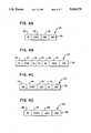
- FIGS. 4A to 4D inclusiveare diagrams showing the format of message packets which are transmitted over the network
- FIG. 5is a timing diagram of the operation of the network when no collision occurs
- FIG. 6is a timing diagram of the operation of the network when a collision occurs
- FIG. 7is a block diagram of a wireless radio local area network operating according to a frequency division multiplexing scheme.
- LANwireless information local area network
- the network 10includes a plurality of stations 12, identified individually as stations 12-1, 12-2, ..., 12-N, among which information is to be transmitted.
- Each station 12includes a transceiver 14 and a user device 16, identified individually as transceivers 14-1, 14-2, ..., 14-N and user devices 16-1, 16-2, ..., 16-N, respectively.
- the user devices 16are coupled to the respective transceivers 14 by output and input lines 18, 20 identified individually as output lines 18-1, 18-2, ..., 18-N and input lines 20-1, 20-2, ..., 20-N.
- the transceiverstransmit and receive radio frequency (RF) signals via antennas 22, identified individually as antennas 22-1, 22-2, ..., 22-N.
- the stations 12may be for example personal computers, printers, data terminals or data handling devices.
- the network 10also includes a distribution system 30 which has an antenna 32, and is adapted to receive messages transmitted from a transmitting station 12 and retransmit the received messages such that the messages are received by all the stations 12 including, of course, the station to which the messages are addressed. All transmissions take place over the same frequency channel.
- a distribution system 30which has an antenna 32, and is adapted to receive messages transmitted from a transmitting station 12 and retransmit the received messages such that the messages are received by all the stations 12 including, of course, the station to which the messages are addressed. All transmissions take place over the same frequency channel.
- the transceiver 14includes a data buffer 40 which receives input data to be transmitted, from the associated user device 16 (FIG. 1).
- the transceiver antenna 22is coupled via line 42 to an RF receiver 44 which provides demodulated data on an output line 46 connected to a data handling unit 48, which also receives an input over a line 50 from the data buffer 40.
- the receiver 44also provides a carrier detect signal on a line 51 in response to detection of a carrier signal.
- the data handling unit 48is coupled via lines 54 and 56 to a timing control circuit 52.
- the data handling unit 48provides decoding, buffer storage and comparison capabilities as will be discussed hereinafter.
- the timing control circuit 52controls the timing operations of the data handling unit 48.
- the data handling unit 48has an output line 58 connected to an RF transmitter 60 which modulates the applied data and is coupled over a line 62 to the antenna 22.
- the data handling unit 48also has an output connected to the line 20 which is coupled to the associated user device 16.
- the antenna 32is connected over a line 70 to an RF receiver 72 which demodulates the received signals, and has a data output line 74 and a carrier detect output line 75, both coupled to a data handling unit 76 which is coupled via lines 78 and 80 to a timing control circuit 82.
- the data handling unit 76provides decoding and buffer storage capabilities as will be discussed hereinafter.
- the timing control circuit 82includes timer devices for defining the timing intervals T1, T2, T3, discussed subsequently.
- the data handling unit 76has an output line 84 coupled to an RF transmitter 86 which modulates the applied data and is coupled over a line 88 to the antenna 32.
- the networkis synchronized under the control of synchronizing packets, referred to as heartbeat packets HBT, which are transmitted by the distribution system 30 at regular intervals defining first timing intervals T1, of successive timing frames FR1, FR2, etc.
- the heartbeat packets HBTare received by all the stations 12 and are recognized as heartbeat packets HBT by decoders (not shown) in the respective data handling units 48 in the stations 12.
- FIG. 4Athere is shown the format of a heartbeat packet 100 transmitted on the network 10.
- the heartbeat packet 100includes a preamble (PR) portion 102, a start delimiter portion 104, and identification code (HBT) portion 106, and an end delimiter portion 108.
- the preamble portion 102permits the receivers 44 (FIG. 2) to adjust the control variables, such as gain and to ensure bit synchronization.
- FIG. 5there is shown a timing diagram for the operation of the network 10 when no collisions occur.
- an HBT packet 110is transmitted by the distribution system 30 and received by all the stations 12. Since it is assumed that at this time, no station 12 desires to transmit information, the remaining timing intervals T2 and T3 of the first timing frame do not contain any transmissions.
- a further HBT packet 112is transmitted. It is assumed that station No. 1 desires to transmit a message at this time. Consequently, after recognition of the end delimiter portion of the HBT packet the timing control unit 52 (FIG. 2) in station No.
- FIG. 4Bthere is shown the format of a typical information packet 120.
- the information packetcontains a preamble portion 122, a start delimiter portion 124, an identification code (IC) portion 126, and an end delimiter portion 134.
- the destination address (DA) portion 128, the source address (8A) portion 130 and the data portion 132are directly taken from the message delivered by the user device 16 over the output line 18.
- the illustrated format in FIG. 4Bis only applicable to the first packet of a message. All subsequent packets of the message contain a data portion but no address portions.
- the information packet 114transmitted by station No. 1 during time interval T2 of timing frame FR2 is received by the distribution system 30 and temporarily stored in a buffer (not shown) included in the data handling unit 76.
- an information packet (IAl) 140containing the information just received, is transmitted by the distribution system 30 instead of a heartbeat packet. All the stations 12 recognize the packet as an information packet, by decoding of the identification code portion thereof in the data handling units 48 of the stations, and maintain timing frame synchronization with the information packet 140, in the same manner as with a heartbeat packet HBT.
- no station 12may commence a message transmission in response to receiving an information packet, as opposed to a heartbeat packet.
- timing interval T2 of timing frame FR3only the already transmitting station No. 1, may transmit.
- the data handling units 48 in the other stationsno longer see a transmission enabling condition and are consequently inhibited from commencing a message transmission during timing interval T2 of timing frame FR3.
- the transmitting station No. 1transmits a further portion of its message in the form of an information packet (IA2) 142.
- This information packet (IA2)is then retransmitted as packet 144 during the first timing interval Tl of timing frame FR4.
- This procedurecontinues, as indicated by packets IA3, IA4 in FIG. 5 until the entire message has been transmitted by station No. 1 and received by its destination station whereafter the distribution system 30 again transmits heartbeat (HBT) packets to maintain network synchronization.
- HBTheartbeat
- the first reception conditionis that, due to the aforementioned "capture" effect, the signals of one of the transmitted information packets are totally masked by the signals of the other information packet.
- the distribution system 30therefore transmits, during timing interval Tl of timing frame FR3, the information packet IAl, as shown by reference 158. As described with reference to FIG. 5, the information packet IAl is received by all the stations 12.
- the data handling units 48 of the transmitting stations No. 1 and No. 3compare the received information packet 158 with the transmitted information packets 154 and 156 which are stored in a buffer register (not shown) in the respective data handling unit 48.
- the comparison at the transmitting station No. 1results in a match, since the information packets 154 and 158 are identical.
- Station No. 1transmits a further information packet (IA2) 160 during timing interval T2 of timing frame FR3.
- the comparison at the transmitting station No. 3results in a mismatch, since at least the source address portions of the information packets IAl and IBl are different i.e. station No. 3 does not recognize its address as the source address in the received information packet IAl.
- This mismatchserves as a local "collision detect” i.e. simultaneous transmissions by two stations 12 are detected by station No. 3.
- the data handling unit 48 of station No. 3transmits a collision reporting packet (CDT) 162 during timing interval T3 of timing frame FR3, and reports a detected collision to the user device 16 of station No. 3 over the line 20.
- CDTcollision reporting packet
- a random timer (not shown) included in the user device 16 of station No. 3is triggered, and a retry is initiated when the random timer times out.
- the collision reporting packet 170includes a preamble portion 172, a start delimiter position 174, a collision detect (CDT) portion 176, a source address portion (SA) 178, containing the address of the station which detected the mismatch, and an end delimiter portion 180.
- the inclusion of the source address portion (SA) 178 in the collision reporting packet 170has the advantage that, if two or more stations are reporting collisions, total signal cancellation is not possible, since the packets are not identical.
- the collision reporting packetcould contain a scrambled version of the station address, obtained for example by subjecting the station address to an encryption algorithm such as a randomly seeded scrambling polynomial, whereby long length station addresses may be replaced by changing shorter length encrypted codes.
- the collision reporting packetis limited to just the source address. The transmission of such a signal is sufficient to cause the provision of a carrier detect signal on the line 75 in the distribution system 30.
- the collision reporting packet (CDT) 162 transmitted by station No. 3 during timing interval T3 of timing frame FR3is received by the distribution system 30.
- the receipt of a collision reporting packetis identified by a decoding operation within the data handling unit 76 which is then caused to transmit during the timing interval Tl of the next timing frame FR4, a collision acknowledgement packet (CAKT) 190, instead of a heartbeat packet or a retransmitted information packet.
- CAKTcollision acknowledgement packet
- the distribution system 30is further arranged to respond to the receipt of such carrier detect signal during such timing interval, to transmit a collision acknowledgement packet (CAKT).
- CAKTcollision acknowledgement packet
- the collision acknowledgement packet 190is shown as including a preamble portion 192, a start delimiter portion 194, a collision acknowledgement code (CAKT) portion 196 and an end delimiter portion 198.
- CAKTcollision acknowledgement code
- the receipt by the stations 12 of the collision acknowledgement packet 190informs all user devices 16 over line 20 that a collision has occurred. Stations 1 and 3 then terminate message transmission, and by means of a random timer included in the user device 16 cause a transmission retry at a later random time.
- a heartbeat packet (HBT) 200is transmitted by the distribution system 30, thereby returning the network 10 to a condition when any station 12 can commence to transmit a message, in the manner described hereinabove.
- HBTheartbeat packet
- the second reception condition at the distribution system 30, during timing interval T2 of timing frame FR2is that the capture effect is not effective, for example if approximately equal strength signals are received from two transmitting stations.
- This conditionmay be detected at the distribution system 30 for example by detecting that a timer set at the commencement of timing interval T2 has expired without an end of transmission code (134 in FIG. 4B) having been detected.
- clock samples recovered at the distribution system 30 from the received datamay be monitored and irregularities in such monitored clock signals used to provide a signal indicating that such clock signals must have come from more than one station.
- the distribution system 30fails to detect a valid information packet, in other words, if an indecipherable information packet is detected, the distribution system responds by transmitting a collision acknowledgement packet (FIG. 4D) during the next timing interval Tl.
- a collision acknowledgement packetFOG. 4D
- FIG. 7there is shown a local area network 10A employing a frequency division multiplexed mode using three transmission channels identified by transmission frequencies f 1 , f 2 and f 3 .
- the network 10Aincludes a distribution system 30A and stations 12A, identified individually as 12A-1 to 12A-N.
- stations 12Aidentified individually as 12A-1 to 12A-N.
- circuit components corresponding to those in the network 10 of FIG. 1are identified by identical reference numbers with an A suffix.
- the frequency f 1is used for transmission from the distribution system 30A.
- the frequencies f 2 and f 3are used for transmissions from the stations 12A.
- a station 12A desiring to transmit a messageupon detecting silence (absence of a carrier signal) on the f 1 channel, sends an information packet on the f 2 channel.
- the distribution system 30Aretransmits the received information packet on the f 1 channel.
- the stations 12Acompare the information packet received on the f 1 channel with the information packet, if any, which they transmitted on the f 2 channel. In the case of a mismatch, a collision reporting packet is transmitted on the f 3 channel by any station 12A which detects such a mismatch.
- the distribution system 30Aresponds by transmitting a collision acknowledge condition on the f 1 channel.
- the distribution system 30Amay itself detect a collision, as explained in connection with the first embodiment, and respond by transmitting collision acknowledgement condition on the f 1 channel immediately. In this manner all stations on the f 2 channel will explicitly detect the collision.
- the described networks 10 and 10Ahave the advantage that even though a transmitting station 12 or 12A captures the transmission channel, collision with another transmitting station 12 or 12A can be reliably reported, and message transmission aborted for a subsequent retry.
Landscapes
- Engineering & Computer Science (AREA)
- Computer Networks & Wireless Communication (AREA)
- Signal Processing (AREA)
- Mobile Radio Communication Systems (AREA)
- Small-Scale Networks (AREA)
Abstract
Description
Claims (9)
Priority Applications (4)
| Application Number | Priority Date | Filing Date | Title |
|---|---|---|---|
| US07/507,558US5040175A (en) | 1990-04-11 | 1990-04-11 | Wireless information transmission system |
| JP10340091AJP3126406B2 (en) | 1990-04-11 | 1991-04-09 | Wireless information communication method |
| EP91303200AEP0452124B1 (en) | 1990-04-11 | 1991-04-11 | Wireless information transmission system |
| DE69127923TDE69127923T2 (en) | 1990-04-11 | 1991-04-11 | Wireless information transmission system |
Applications Claiming Priority (1)
| Application Number | Priority Date | Filing Date | Title |
|---|---|---|---|
| US07/507,558US5040175A (en) | 1990-04-11 | 1990-04-11 | Wireless information transmission system |
Publications (1)
| Publication Number | Publication Date |
|---|---|
| US5040175Atrue US5040175A (en) | 1991-08-13 |
Family
ID=24019124
Family Applications (1)
| Application Number | Title | Priority Date | Filing Date |
|---|---|---|---|
| US07/507,558Expired - LifetimeUS5040175A (en) | 1990-04-11 | 1990-04-11 | Wireless information transmission system |
Country Status (4)
| Country | Link |
|---|---|
| US (1) | US5040175A (en) |
| EP (1) | EP0452124B1 (en) |
| JP (1) | JP3126406B2 (en) |
| DE (1) | DE69127923T2 (en) |
Cited By (37)
| Publication number | Priority date | Publication date | Assignee | Title |
|---|---|---|---|---|
| US5159592A (en)* | 1990-10-29 | 1992-10-27 | International Business Machines Corporation | Network address management for a wired network supporting wireless communication to a plurality of mobile users |
| FR2689657A1 (en)* | 1992-04-02 | 1993-10-08 | Inst Nat Rech Inf Automat | Radio communication system serving multiple stations |
| FR2689658A1 (en)* | 1992-04-02 | 1993-10-08 | Inst Nat Rech Inf Automat | Installation for data transmission, of the radio network type, and corresponding method. |
| WO1994017616A1 (en)* | 1993-01-26 | 1994-08-04 | Inria Institut National De Recherche En Informatique Et En Automatique | Radio network-type data transmission method and facility |
| US5371494A (en)* | 1988-12-15 | 1994-12-06 | Laboratoire Europeen De Recherches Electroniques Avancees | Method for optimizing the transmission of authorization of access to a network comprising open channels |
| US5379290A (en)* | 1992-08-14 | 1995-01-03 | Ncr Corporation | Wireless local area network transmission system |
| US5384777A (en)* | 1993-04-19 | 1995-01-24 | International Business Machines Corporation | Adaptive medium access control scheme for wireless LAN |
| US5390326A (en)* | 1993-04-30 | 1995-02-14 | The Foxboro Company | Local area network with fault detection and recovery |
| US5414694A (en)* | 1993-02-19 | 1995-05-09 | Advanced Micro Devices, Inc. | Address tracking over repeater based networks |
| US5422887A (en)* | 1991-11-27 | 1995-06-06 | Ncr Corporation | Medium access protocol for wireless local area network |
| US5442633A (en)* | 1992-07-08 | 1995-08-15 | International Business Machines Corporation | Shortcut network layer routing for mobile hosts |
| US5517504A (en)* | 1994-07-29 | 1996-05-14 | Motorola, Inc. | Method and system for providing uplink/downlink collision avoidance in a wireless communication system |
| WO1996019877A1 (en)* | 1994-12-20 | 1996-06-27 | 3Com Corporation | Radio based collision detection for wireless communication system |
| US5581707A (en)* | 1994-07-27 | 1996-12-03 | Psc, Inc. | System for wireless collection of data from a plurality of remote data collection units such as portable bar code readers |
| EP0634853A3 (en)* | 1993-07-05 | 1996-12-11 | Victor Company Of Japan | Wireless communication network system. |
| US5604869A (en)* | 1993-07-09 | 1997-02-18 | Apple Computer, Inc. | System and method for sending and responding to information requests in a communications network |
| EP0795948A1 (en)* | 1993-08-11 | 1997-09-17 | First Pacific Networks, Inc. | System for utility demand monitoring and control |
| US5719868A (en)* | 1995-10-05 | 1998-02-17 | Rockwell International | Dynamic distributed, multi-channel time division multiple access slot assignment method for a network of nodes |
| US5790398A (en)* | 1994-01-25 | 1998-08-04 | Fujitsu Limited | Data transmission control method and apparatus |
| US5805458A (en)* | 1993-08-11 | 1998-09-08 | First Pacific Networks | System for utility demand monitoring and control |
| US5818725A (en)* | 1993-08-11 | 1998-10-06 | First Pacific Networks | System for utility demand monitoring and control |
| US5949760A (en)* | 1997-03-21 | 1999-09-07 | Rockwell International Corporation | Simultaneous channel access transmission method for a multi-hop communications radio network |
| US6028866A (en)* | 1995-12-22 | 2000-02-22 | U.S. Philips Corporation | System for communicating between a group of apparatuses |
| US6044268A (en)* | 1997-07-16 | 2000-03-28 | Telefonaktiebolaget Lm Ericsson Ab | System and method for providing intercom and multiple voice channels in a private telephone system |
| EP0944181A3 (en)* | 1991-08-23 | 2000-06-28 | Kabushiki Kaisha Toshiba | Radio information communication system using multi-carrier spread spectrum transmission system and signal collision detection method |
| US6381218B1 (en)* | 1998-09-11 | 2002-04-30 | Compaq Computer Corporation | Network controller system that uses directed heartbeat packets |
| US6690657B1 (en) | 2000-02-25 | 2004-02-10 | Berkeley Concept Research Corporation | Multichannel distributed wireless repeater network |
| US20040053631A1 (en)* | 2000-09-29 | 2004-03-18 | Spicer John Joseph | Electronic systems |
| WO2005015774A1 (en)* | 2003-08-08 | 2005-02-17 | Clipsal Integrated Systems Pty Ltd | Radio network communication system and protocol using an automatic repeater |
| WO2005015751A1 (en)* | 2003-08-08 | 2005-02-17 | Clipsal Integrated Systems Pty Ltd | “collision detection in a non-dominant bit radio network communication system” |
| US6891822B1 (en)* | 2000-09-08 | 2005-05-10 | Sharewave, Inc. | Method and apparatus for transferring isocronous data within a wireless computer network |
| US20060256798A1 (en)* | 2003-08-08 | 2006-11-16 | Clipsal Integrated Systems Pty Ltd. | Radio network communication system and protocol |
| AU2004301958B2 (en)* | 2003-08-08 | 2009-06-04 | Clipsal Integrated Systems Pty Ltd | Radio network communication system and protocol using an automatic repeater |
| US20090322482A1 (en)* | 2008-06-30 | 2009-12-31 | Frederick Schuessler | Delimited Read Command for Efficient Data Access from Radio Frequency Identification (RFID) Tags |
| US20100195656A1 (en)* | 2008-04-25 | 2010-08-05 | Yosuke Matsushita | Communication apparatus and communication method |
| AU2009201888B2 (en)* | 2003-08-08 | 2011-09-15 | Clipsal Integrated Systems Pty Ltd | Collision detection in a non-dominant bit radio network communication system |
| US9444837B2 (en) | 2006-01-13 | 2016-09-13 | Thomson Licensing | Process and devices for selective collision detection |
Families Citing this family (7)
| Publication number | Priority date | Publication date | Assignee | Title |
|---|---|---|---|---|
| CH685897A5 (en)* | 1993-01-26 | 1995-10-31 | Royale Consultants Ltd | Method and apparatus for bidirectional Informationsuebertragung (protocol) |
| GB9304622D0 (en) | 1993-03-06 | 1993-04-21 | Ncr Int Inc | Wireless local area network apparatus |
| GB2292048B (en)* | 1994-07-30 | 1998-12-16 | Motorola Ltd | Communications device and method with adaptive burst transmission time and other features |
| DE19638424C1 (en)* | 1996-09-19 | 1998-01-22 | Siemens Ag | Clocked serial data transmission method especially for data blocks of uniform length |
| EP0966808A2 (en)* | 1997-11-14 | 1999-12-29 | Tektronix, Inc. | Method of operating a digital data distribution network |
| WO1999043122A1 (en)* | 1998-02-19 | 1999-08-26 | Mitsubishi International Gmbh | Method for transmitting digital coded radio signals with error detection in the signal transmitter |
| EP1300986A1 (en)* | 2001-10-08 | 2003-04-09 | Thomson Licensing S.A. | Methods and devices for radio link adaptation |
Citations (12)
| Publication number | Priority date | Publication date | Assignee | Title |
|---|---|---|---|---|
| US4271513A (en)* | 1978-05-19 | 1981-06-02 | Nippon Telegraph And Telephone Public Corporation | Method and apparatus for carrying out loopback test |
| US4347609A (en)* | 1979-09-04 | 1982-08-31 | Fujitsu Fanuc Limited | Method and system for transmission of serial data |
| US4573154A (en)* | 1982-10-08 | 1986-02-25 | Hitachi, Ltd. | Data communication system with error detection/correction |
| EP0184383A2 (en)* | 1984-12-06 | 1986-06-11 | AT&T Corp. | A wireless PBX/LAN system with optimum combining |
| US4725834A (en)* | 1984-02-27 | 1988-02-16 | American Telephone And Telegraph Company, At&T Bell Laboratories | Reliable broadcast protocol for a token passing bus network |
| US4755990A (en)* | 1987-10-08 | 1988-07-05 | Karl Suss America, Inc. | Collision avoidance in a multinode data communication network |
| EP0286614A1 (en)* | 1987-04-03 | 1988-10-12 | Telefonaktiebolaget L M Ericsson | Method and equipment for synchronizing and transmitting information in a radio communication network |
| US4789983A (en)* | 1987-03-05 | 1988-12-06 | American Telephone And Telegraph Company, At&T Bell Laboratories | Wireless network for wideband indoor communications |
| EP0294133A2 (en)* | 1987-06-05 | 1988-12-07 | AT&T Corp. | Protocols for very high-speed optical LANs |
| GB2206468A (en)* | 1987-06-30 | 1989-01-05 | Oki Electric Ind Co Ltd | Contention control |
| US4839892A (en)* | 1987-08-27 | 1989-06-13 | Nec Corporation | Concentrator system capable of completing emergency calls under congested traffic |
| US4872205A (en)* | 1987-08-21 | 1989-10-03 | American Telephone And Telegraph Company | Radio communication system having autonomously selected transmission frequencies |
Family Cites Families (2)
| Publication number | Priority date | Publication date | Assignee | Title |
|---|---|---|---|---|
| NL189062C (en)* | 1980-02-15 | 1992-12-16 | Philips Nv | METHOD AND SYSTEM FOR TRANSFER OF DATA PACKAGES. |
| JPS60109948A (en)* | 1983-11-19 | 1985-06-15 | Ricoh Co Ltd | Multiple access communication method |
- 1990
- 1990-04-11USUS07/507,558patent/US5040175A/ennot_activeExpired - Lifetime
- 1991
- 1991-04-09JPJP10340091Apatent/JP3126406B2/ennot_activeExpired - Lifetime
- 1991-04-11DEDE69127923Tpatent/DE69127923T2/ennot_activeExpired - Fee Related
- 1991-04-11EPEP91303200Apatent/EP0452124B1/ennot_activeExpired - Lifetime
Patent Citations (12)
| Publication number | Priority date | Publication date | Assignee | Title |
|---|---|---|---|---|
| US4271513A (en)* | 1978-05-19 | 1981-06-02 | Nippon Telegraph And Telephone Public Corporation | Method and apparatus for carrying out loopback test |
| US4347609A (en)* | 1979-09-04 | 1982-08-31 | Fujitsu Fanuc Limited | Method and system for transmission of serial data |
| US4573154A (en)* | 1982-10-08 | 1986-02-25 | Hitachi, Ltd. | Data communication system with error detection/correction |
| US4725834A (en)* | 1984-02-27 | 1988-02-16 | American Telephone And Telegraph Company, At&T Bell Laboratories | Reliable broadcast protocol for a token passing bus network |
| EP0184383A2 (en)* | 1984-12-06 | 1986-06-11 | AT&T Corp. | A wireless PBX/LAN system with optimum combining |
| US4789983A (en)* | 1987-03-05 | 1988-12-06 | American Telephone And Telegraph Company, At&T Bell Laboratories | Wireless network for wideband indoor communications |
| EP0286614A1 (en)* | 1987-04-03 | 1988-10-12 | Telefonaktiebolaget L M Ericsson | Method and equipment for synchronizing and transmitting information in a radio communication network |
| EP0294133A2 (en)* | 1987-06-05 | 1988-12-07 | AT&T Corp. | Protocols for very high-speed optical LANs |
| GB2206468A (en)* | 1987-06-30 | 1989-01-05 | Oki Electric Ind Co Ltd | Contention control |
| US4872205A (en)* | 1987-08-21 | 1989-10-03 | American Telephone And Telegraph Company | Radio communication system having autonomously selected transmission frequencies |
| US4839892A (en)* | 1987-08-27 | 1989-06-13 | Nec Corporation | Concentrator system capable of completing emergency calls under congested traffic |
| US4755990A (en)* | 1987-10-08 | 1988-07-05 | Karl Suss America, Inc. | Collision avoidance in a multinode data communication network |
Cited By (59)
| Publication number | Priority date | Publication date | Assignee | Title |
|---|---|---|---|---|
| US5371494A (en)* | 1988-12-15 | 1994-12-06 | Laboratoire Europeen De Recherches Electroniques Avancees | Method for optimizing the transmission of authorization of access to a network comprising open channels |
| US5159592A (en)* | 1990-10-29 | 1992-10-27 | International Business Machines Corporation | Network address management for a wired network supporting wireless communication to a plurality of mobile users |
| EP0944181A3 (en)* | 1991-08-23 | 2000-06-28 | Kabushiki Kaisha Toshiba | Radio information communication system using multi-carrier spread spectrum transmission system and signal collision detection method |
| US5422887A (en)* | 1991-11-27 | 1995-06-06 | Ncr Corporation | Medium access protocol for wireless local area network |
| EP0849914A3 (en)* | 1992-04-02 | 2006-08-23 | Inria Institut National De Recherche En Informatique Et En Automatique | Collision detection by transmitting data over a radio network |
| FR2689657A1 (en)* | 1992-04-02 | 1993-10-08 | Inst Nat Rech Inf Automat | Radio communication system serving multiple stations |
| FR2689658A1 (en)* | 1992-04-02 | 1993-10-08 | Inst Nat Rech Inf Automat | Installation for data transmission, of the radio network type, and corresponding method. |
| WO1993020636A1 (en)* | 1992-04-02 | 1993-10-14 | Inria Institut National De Recherche En Informatique Et En Automatique | Radio network type data transmission installation and method |
| US6023457A (en)* | 1992-04-02 | 2000-02-08 | Inria Institut National De Recherche En Informatique Et En Automatique | Data transmission installation of the radio network type, and corresponding method |
| US5689510A (en)* | 1992-04-02 | 1997-11-18 | Inria Institut National De Recherche En Informatique Et En Automatique | Data transmission installation of the radio network type, and corresponding method |
| EP0862298A3 (en)* | 1992-04-02 | 2006-08-23 | Inria Institut National De Recherche En Informatique Et En Automatique | Installation of a radio data transmission network with routing |
| US5442633A (en)* | 1992-07-08 | 1995-08-15 | International Business Machines Corporation | Shortcut network layer routing for mobile hosts |
| US5379290A (en)* | 1992-08-14 | 1995-01-03 | Ncr Corporation | Wireless local area network transmission system |
| US5638449A (en)* | 1993-01-26 | 1997-06-10 | Inria Institut National De Recherche En Informatique Et En Automatique | Data transmission installation of the radio network type, and corresponding process |
| WO1994017616A1 (en)* | 1993-01-26 | 1994-08-04 | Inria Institut National De Recherche En Informatique Et En Automatique | Radio network-type data transmission method and facility |
| US5414694A (en)* | 1993-02-19 | 1995-05-09 | Advanced Micro Devices, Inc. | Address tracking over repeater based networks |
| US5384777A (en)* | 1993-04-19 | 1995-01-24 | International Business Machines Corporation | Adaptive medium access control scheme for wireless LAN |
| US5390326A (en)* | 1993-04-30 | 1995-02-14 | The Foxboro Company | Local area network with fault detection and recovery |
| EP0634853A3 (en)* | 1993-07-05 | 1996-12-11 | Victor Company Of Japan | Wireless communication network system. |
| US5604869A (en)* | 1993-07-09 | 1997-02-18 | Apple Computer, Inc. | System and method for sending and responding to information requests in a communications network |
| EP0795948A1 (en)* | 1993-08-11 | 1997-09-17 | First Pacific Networks, Inc. | System for utility demand monitoring and control |
| US5805458A (en)* | 1993-08-11 | 1998-09-08 | First Pacific Networks | System for utility demand monitoring and control |
| US5818725A (en)* | 1993-08-11 | 1998-10-06 | First Pacific Networks | System for utility demand monitoring and control |
| US5790398A (en)* | 1994-01-25 | 1998-08-04 | Fujitsu Limited | Data transmission control method and apparatus |
| US5581707A (en)* | 1994-07-27 | 1996-12-03 | Psc, Inc. | System for wireless collection of data from a plurality of remote data collection units such as portable bar code readers |
| US5517504A (en)* | 1994-07-29 | 1996-05-14 | Motorola, Inc. | Method and system for providing uplink/downlink collision avoidance in a wireless communication system |
| GB2310978B (en)* | 1994-12-20 | 2000-02-02 | 3Com Corp | Radio based collision detection for wireless communication system |
| US5657326A (en)* | 1994-12-20 | 1997-08-12 | 3Com Corporation | Radio based collision detection for wireless communication system |
| GB2310978A (en)* | 1994-12-20 | 1997-09-10 | 3Com Corp | Radio based collision detection for wireless communication system |
| WO1996019877A1 (en)* | 1994-12-20 | 1996-06-27 | 3Com Corporation | Radio based collision detection for wireless communication system |
| US5719868A (en)* | 1995-10-05 | 1998-02-17 | Rockwell International | Dynamic distributed, multi-channel time division multiple access slot assignment method for a network of nodes |
| US6028866A (en)* | 1995-12-22 | 2000-02-22 | U.S. Philips Corporation | System for communicating between a group of apparatuses |
| US5949760A (en)* | 1997-03-21 | 1999-09-07 | Rockwell International Corporation | Simultaneous channel access transmission method for a multi-hop communications radio network |
| US6044268A (en)* | 1997-07-16 | 2000-03-28 | Telefonaktiebolaget Lm Ericsson Ab | System and method for providing intercom and multiple voice channels in a private telephone system |
| US6381218B1 (en)* | 1998-09-11 | 2002-04-30 | Compaq Computer Corporation | Network controller system that uses directed heartbeat packets |
| US6690657B1 (en) | 2000-02-25 | 2004-02-10 | Berkeley Concept Research Corporation | Multichannel distributed wireless repeater network |
| US6891822B1 (en)* | 2000-09-08 | 2005-05-10 | Sharewave, Inc. | Method and apparatus for transferring isocronous data within a wireless computer network |
| US20040053631A1 (en)* | 2000-09-29 | 2004-03-18 | Spicer John Joseph | Electronic systems |
| SG148878A1 (en)* | 2003-08-08 | 2009-01-29 | Clipsal Integrated Systems Pty | Collision detection in a non-dominant bit radio network communication system |
| US7656793B2 (en) | 2003-08-08 | 2010-02-02 | Clipsal Integrated Systems Pty Ltd | Collision detection in a non-dominant bit radio network communication system |
| US20060192697A1 (en)* | 2003-08-08 | 2006-08-31 | Quick Ashleigh G | Collision detection in a non-dominant bit radio network communication system |
| US20060256798A1 (en)* | 2003-08-08 | 2006-11-16 | Clipsal Integrated Systems Pty Ltd. | Radio network communication system and protocol |
| US20060256746A1 (en)* | 2003-08-08 | 2006-11-16 | Clipsal Integrated Systems Pty Ltd. | Radio network communication system and protocol using an automatic repeater |
| WO2005015774A1 (en)* | 2003-08-08 | 2005-02-17 | Clipsal Integrated Systems Pty Ltd | Radio network communication system and protocol using an automatic repeater |
| AU2004301958B2 (en)* | 2003-08-08 | 2009-06-04 | Clipsal Integrated Systems Pty Ltd | Radio network communication system and protocol using an automatic repeater |
| AU2004301958C1 (en)* | 2003-08-08 | 2009-12-17 | Clipsal Integrated Systems Pty Ltd | Radio network communication system and protocol using an automatic repeater |
| US8724614B2 (en) | 2003-08-08 | 2014-05-13 | Clipsal Integrated Systems Pty Ltd | Radio network communication system and protocol |
| US8606279B2 (en) | 2003-08-08 | 2013-12-10 | Clipsal Integrated Systems Pty Ltd. | Radio network communication system and protocol using an automatic repeater |
| US20100034188A1 (en)* | 2003-08-08 | 2010-02-11 | Clipsal Integrated Systems Pty Ltd. | Radio network communication system and protocol |
| WO2005015751A1 (en)* | 2003-08-08 | 2005-02-17 | Clipsal Integrated Systems Pty Ltd | “collision detection in a non-dominant bit radio network communication system” |
| EP1665618A4 (en)* | 2003-08-08 | 2011-01-19 | Clipsal Integrated Systems Pty Ltd | Radtio network communication system and protocol |
| US8000307B2 (en)* | 2003-08-08 | 2011-08-16 | Clipsal Integrated Systems Pty Ltd | Radio network communication system and protocol |
| AU2009201888B2 (en)* | 2003-08-08 | 2011-09-15 | Clipsal Integrated Systems Pty Ltd | Collision detection in a non-dominant bit radio network communication system |
| CN1849758B (en)* | 2003-08-08 | 2012-04-25 | 奇胜集成系统控股有限公司 | Radio network communication systems and protocols using automatic transponders |
| US9444837B2 (en) | 2006-01-13 | 2016-09-13 | Thomson Licensing | Process and devices for selective collision detection |
| US20100195656A1 (en)* | 2008-04-25 | 2010-08-05 | Yosuke Matsushita | Communication apparatus and communication method |
| US9008090B2 (en)* | 2008-04-25 | 2015-04-14 | Panasonic Intellectual Property Management Co.,Ltd. | Communication apparatus and communication method |
| US8598990B2 (en)* | 2008-06-30 | 2013-12-03 | Symbol Technologies, Inc. | Delimited read command for efficient data access from radio frequency identification (RFID) tags |
| US20090322482A1 (en)* | 2008-06-30 | 2009-12-31 | Frederick Schuessler | Delimited Read Command for Efficient Data Access from Radio Frequency Identification (RFID) Tags |
Also Published As
| Publication number | Publication date |
|---|---|
| DE69127923T2 (en) | 1998-04-09 |
| EP0452124A2 (en) | 1991-10-16 |
| EP0452124B1 (en) | 1997-10-15 |
| EP0452124A3 (en) | 1992-04-08 |
| DE69127923D1 (en) | 1997-11-20 |
| JP3126406B2 (en) | 2001-01-22 |
| JPH05316113A (en) | 1993-11-26 |
Similar Documents
| Publication | Publication Date | Title |
|---|---|---|
| US5040175A (en) | Wireless information transmission system | |
| US5339316A (en) | Wireless local area network system | |
| US5329531A (en) | Method of accessing a communication medium | |
| US5828663A (en) | Access control system for wireless-lan terminals | |
| JP2804461B2 (en) | Frequency management method in frequency hopping wireless communication | |
| JP5497189B2 (en) | Retransmission technology in wireless networks | |
| US5379290A (en) | Wireless local area network transmission system | |
| JP2733110B2 (en) | Wireless signal transmission method | |
| JP3846715B2 (en) | Wireless communication system | |
| US7801063B2 (en) | Method and apparatus for rate fallback in a wireless communication system | |
| US9198196B2 (en) | Wireless communication apparatus | |
| JP3530141B2 (en) | Wireless LAN system and wireless LAN system signal collision avoidance method | |
| US6292494B1 (en) | Channel hopping protocol | |
| US7613146B2 (en) | Method and system for reliable data transmission in wireless networks | |
| JPH0761072B2 (en) | Satellite communication system | |
| US20140362843A1 (en) | System and Method for Collision Resolution | |
| CN101159518A (en) | Communication method and communication device | |
| WO2003017024A2 (en) | Mechanism for detecting intrusion and jamming attempts in a shared media based communications network | |
| US7680090B2 (en) | System and method for monitoring network traffic | |
| JPH03104335A (en) | Signal transmission system | |
| CN111065168B (en) | Wireless access method based on co-frequency simultaneous full duplex | |
| KR100357743B1 (en) | An adaptation coding method based on channel status for wireless LAN system | |
| US11882448B2 (en) | System and method for packet detail detection and precision blocking | |
| JP3950081B2 (en) | Wireless relay method and apparatus | |
| JP3245786B2 (en) | Wireless packet collision detection method |
Legal Events
| Date | Code | Title | Description |
|---|---|---|---|
| AS | Assignment | Owner name:NCR CORPORATION, A CORP. OF MARYLAND, OHIO Free format text:ASSIGNMENT OF 1/2 OF ASSIGNORS INTEREST;ASSIGNORS:TUCH, BRUCE T.;MASLEID, MICHAEL A.;REEL/FRAME:005276/0822 Effective date:19900318 | |
| STCF | Information on status: patent grant | Free format text:PATENTED CASE | |
| CC | Certificate of correction | ||
| FPAY | Fee payment | Year of fee payment:4 | |
| FEPP | Fee payment procedure | Free format text:PAYOR NUMBER ASSIGNED (ORIGINAL EVENT CODE: ASPN); ENTITY STATUS OF PATENT OWNER: LARGE ENTITY | |
| FEPP | Fee payment procedure | Free format text:PAYOR NUMBER ASSIGNED (ORIGINAL EVENT CODE: ASPN); ENTITY STATUS OF PATENT OWNER: LARGE ENTITY Free format text:PAYER NUMBER DE-ASSIGNED (ORIGINAL EVENT CODE: RMPN); ENTITY STATUS OF PATENT OWNER: LARGE ENTITY | |
| FPAY | Fee payment | Year of fee payment:8 | |
| FEPP | Fee payment procedure | Free format text:PAYER NUMBER DE-ASSIGNED (ORIGINAL EVENT CODE: RMPN); ENTITY STATUS OF PATENT OWNER: LARGE ENTITY Free format text:PAYOR NUMBER ASSIGNED (ORIGINAL EVENT CODE: ASPN); ENTITY STATUS OF PATENT OWNER: LARGE ENTITY | |
| FPAY | Fee payment | Year of fee payment:12 | |
| REMI | Maintenance fee reminder mailed | ||
| AS | Assignment | Owner name:AT&T CORP., NEW YORK Free format text:ASSIGNMENT OF ASSIGNORS INTEREST;ASSIGNOR:NCR CORPORATION;REEL/FRAME:020773/0814 Effective date:19960329 Owner name:AGERE SYSTEMS INC., PENNSYLVANIA Free format text:ASSIGNMENT OF ASSIGNORS INTEREST;ASSIGNOR:LUCENT TECHNOLOGIES INC.;REEL/FRAME:020773/0752 Effective date:20020531 Owner name:LUCENT TECHNOLOGIES INC., NEW JERSEY Free format text:ASSIGNMENT OF ASSIGNORS INTEREST;ASSIGNOR:AT&T CORP.;REEL/FRAME:020773/0807 Effective date:19960329 |